imd series teflon lined magnetic drive pump
TRANSCRIPT
5 6
L S P f W T H h a g x
CQB16-12-50F
CQB15-15-65F
CQB20-15-75F
CQB25-20-100F
200 56 80 30 90 71 100 45 24 17 22
290 71 115 40 112 90 125 2056 20 25
316 71 120 55 112 90 138 56 27 20 38
360 80 150 60 125 100 165 63 34 26 49
430
435
510
430
65
50
85
65
60
67
76
60
CQB32-20-110F
CQB40-25-120F
CQB50-32-125F
CQB40-40-100F
200
270
225
200
125
65
65
125
148
175
192
148
115
150
158
115
216
244
268
216
105
113
128
105
120
140
130
130
90 90
100 100
120 100
130 100
65
75
90
100
4-φ13
4- M12
4-φ13
4-φ13
4-φ11
4-φ11
4-φ11
4-φ13
4-φ12
4-φ12
4-φ13
4-φ12
n-φd n-φt n-φD
n-φd n-φt
CQB50-32-125FA
CQB50-32-160FA
CQB50-32-200FA
CQB65-50-160FL
CQB65-40-200FA
CQB80-65-160FA
CQB80-50-200FA
CQB100-80-160FL
950
1025
1040
1180
1305
1420
1035
1255
895
920
990
1130
1160
1160
990
1130
590
590
650
720
730
730
650
720
75
100
90
105
130
130
170
130
80
80
80
80
100
100
80
100
395
390
450
500
480
480
150
485
352
392
440
440
420
440
392
500
212
232
260
260
240
240
232
280
24
24
25
24
24
24
24
24
165
165
165
185
200
200
185
220
125
125
125
145
160
160
145
180
100
100
100
110
145
125
125
160
330
330
380
435
430
430
380
435
140
140
140
150
185
165
165
200
4-φ18
4-M16
4- M16
4- M16
4- M16
8- M16
4- M16
8- M16
4- M16
4-φ18
4-φ18
4-φ18
4- M16
8- M16
8-φ18
8- M16
IMD40-25-165FAIMD50-40-165F
IMD65-50-130FIMD80-65-140F
IMD80-65-140FIMD100-80-180F
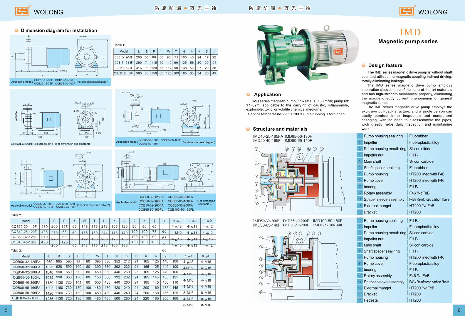
Dimension diagram for installation
Table 1:
Model
Applicable model: (For dimension see table 1)
Applicable model: (For dimension see diagram)Applicable model: (For dimension see diagram)
(For dimension see table 2)Applicable model:
CQB50-32-125FA CQB65-40-200FA
CQB50-32-160FA CQB80-65-160FA
CQB50-32-200FA CQB80-50-200FA
CQB65-50-160FL CQB100-80-160FL
Applicable model: (For dimension see table 3)
Table 2:
Model
Table 3:
Model
The IMD series magnetic drive pump is without shaft seal and utilizes the magnetic coupling indirect driving, totally eliminating leakage. The IMD series magnetic drive pump employs separation sleeve made of the state-of-the-art materials and has high-strength mechanical property, eliminating the magnetic eddy current phenomenon of general magnetic pump. The IMD series magnetic drive pump employs the exclusive pull-back structure, and a single person can easily conduct inner inspection and component changing, with no need to disassemmble the pipes, wich greatly helps daily inspection and maintaining work.
Magnetic pump series
Application3 IMD series magnetic pump, flow rate: 1~160 m /h; pump lift:
17~62m, applicable to the carrying of caustic, inflammable, explosible, toxic, or volatile chemical mediums.
Service temperature: -20 ~100 . Idle running is forbidden.℃ ℃
Design feature
Structure and materials
Pump housing seal ring
Impeller
Pump housing mouth ring
Impeller nut
Main shaft
Shaft spacer seal ring
Pump housing
Pump cover
bearing
Rotary assembly
Spacer sleeve assembly
External manget
Bracket
Fluorubber
Fluoroplastic alloy
Silicon nitride
Fill F4
Silicon carbide
Fluorubber
HT200 lined with F46
HT200 lined with F46
Fill F4
F46 /NdFeB
HT200 /NdFeB
HT200
F46 / Reinforced carbon fibere
Pump housing seal ring
Impeller
Pump housing mouth ring
Impeller nut
Main shaft
Shaft spacer seal ring
Pump housing
Pump cover
bearing
Rotary assembly
Spacer sleeve assembly
External manget
Bracket
Pedestal
Fill F4
Fluoroplastic alloy
Silicon carbide
Fill F4
Silicon carbide
Fill F4
HT200 lined with F46
Fluoroplastic alloy
Fill F4
F46 /NdFeB
HT200 /NdFeB
HT200
F46 / Reinforced carbon fibere
HT200
WOLONG WOLONG
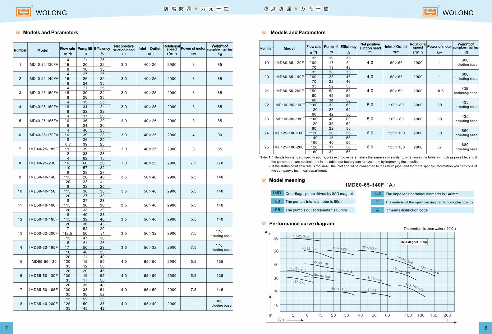
1 IMD40-25-130FA
2 IMD40-25-140FA
3 IMD40-25-150FA
4 IMD40-25-160FA
5 IMD40-25-165FA
6 IMD40-25-170FA
7 IMD40-25-185F
8 IMD40-25-230F
9 IMD50-40-140F
10 IMD50-40-150F
11 IMD50-40-160F
12 IMD50-40-165F
13 IMD50-32-200F
14 IMD50-32-195F
15 IMD65-50-120
16 IMD65-50-130F
17 IMD65-50-165F
18 IMD65-40-200F
20 21 40
4.0 65×50 2900 5.5 13530 15 50
35 12 50
20 20 45
4.0 65×50 2900 5.5 13530 19 55
35 17 56
20 35 40
4.0 65×50 2900 7.5 14530 33 54
35 30 52
15 52 25
4.0 65×40 2900 11 25 50 37
35 45 42
8 37 23
3.5 50×40 2900 5.5 14015 36 36
20 33 39
8 40 28
3.5 50×40 2900 5.5 14015 39 40
20 36 43
7 52 20
3.5 50×32 2900 7.5 12.5 50 31
15 47 38
5 51 25
3.5 50×32 2900 7.5 7 50 28
10 48 33
0.7 39 25
3.0 40×25 2900 3 851 39 28
2 38 28
4 62 15
3.0 40×25 2900 7.5 1706 60 20
10 57 32
8 28 27
3.5 50×40 2900 5.5 14015 26 40
20 23 41
8 32 25
3.5 50×40 2900 5.5 14015 30 38
20 27 39
4 21 25
3.0 40×25 2900 3 856 20 32
8 18 33
4 27 25
3.0 40×25 2900 3 856 26 32
8 24 33
4 31 25
3.0 40×25 2900 3 856 30 32
8 28 33
4 35 25
3.0 40×25 2900 3 856 34 31
8 32 32
4 37 25
3.0 40×25 2900 3 856 36 29
8 34 30
4 40 25
3.0 40×25 2900 4 906 39 28
8 36 29
7 8
19 IMD80-65-120F
20 IMD80-65-140F
21 IMD80-50-200F
22 IMD100-80-160F
23 IMD100-80-180F
24 IMD125-100-160F
25 IMD125-100-200F
35 19 35
4.0 80×65 2900 11 60 17 51
70 13 48
35 28 35
4.0 80×65 2900 11 60 25 46
70 22 46
35 52 50
4.0 80×50 2900 18.5 50 50 55
60 45 56
60 34 50
5.0 100×80 2900 30 100 32 60
120 27 62
60 42 50
5.0 100×80 2900 30 100 40 60
120 35 62
80 22 50
6.0 125×100 2900 30 120 20 56
140 15 56
100 40 50
6.0 125×100 2900 37 120 37 56
160 32 56
10
20
30
40
50
60
105 15 20 30 40 50 60 100 130 160 200
40-25-230
50-32-200 65-40-20080-50-200
50-40-165
50-40-160
40-25-165
40-25-150
65-50-165
80-65-140
65-50-130 80-65-120
100-80-180
100-80-160
125-100-200
125-100-160
m3m /h
5 15Q
H
Models and Parameters
3m /h m % m mm r/min kw kgModelNumber Flow rate Pump lift Efficiency
Net positivesuction head Inlet×Outlet
Rotationalspeed Power of motor
Weight of complete machine
Models and Parameters
3m /h m % m mm r/min kw kgModelNumber Flow rate Pump lift Efficiency
Net positivesuction head Inlet×Outlet
Rotationalspeed Power of motor
Weight of complete machine
Note: 1. * stands for standard specifications; please choose parameters the same as or similar to what are in the table as much as possible, and if
the parameters are not included in the table, our factory can realize them by improving the impeller.
2. If the status point flow rate is too small, the inlet should be connected to the return pipe, and for more specific information you can consult
the company's technical department.
IMD80-65-140F(A)
IMD
80
65
140
F
A
Model meaning
Centrifugal pump drived by IMD magnet
The pump's inlet diameter is 80mm
The pump's outlet diameter is 65mm
The impeller's norminal diameter is 140mm
The material of the liquid carrying part is fluoroplastic alloy
It means distinction code
The medium is clear water(20℃)
Performance curve diagram
IMD Magnet Pump
WOLONG WOLONG
170Including base
170Including base
300Including base
300Including base
300Including base
335Including base
435Including base
435Including base
660Including base
680Including base
165 125 22 140 100 20 4-M16 4-M16
165 125 22 140 100 20 4-M16 4-M16
4- 20
4- 20
185 145 22 150 110 22 4-M16 4- 20
200 160 22 185 145 22 4-M16 4- 204- 18
200 160 22 185 145 22 4-M16 4- 204- 18
200 160 22 165 125 22 4-M16 4- 208- 18
220 180 24 200 160 24 8-M16 4- 258- 18
220 180 24 160 24 8-M16 4- 258- 18
250 210 24 225 180 24 8-M16 4- 258- 18
25
25
40
40
40
40
50
50
50
4- 18
150 110 20 115 85 18 4-M16 4-M12 4- 2025
250 210 24 225 180 24 8-M16 4- 258- 1850
610IMD40-25-130FA 250 70 80 210 160 310 150 150 110 20 115 85 18 4-M16 4-M12 4- 15
610IMD40-25-140FA 250 70 80 210 160 310 150 150 110 20 115 85 18 4-M16 4-M12 4- 15
610IMD40-25-150FA 250 70 80 210 160 310 150 150 110 20 115 85 18 4-M16 4-M12 4- 15
610IMD40-25-160FA 250 70 80 210 160 310 150 150 110 20 115 85 18 4-M16 4-M12 4- 15
610IMD40-25-165FA 250 70 80 210 160 310 150 150 110 20 115 85 18 4-M16 4-M12 4- 15
610IMD40-25-170FA 250 70 80 210 160 310 150 150 110 20 115 85 18 4-M16 4-M12 4- 15
610IMD40-25-185F 250 70 80 210 160 310 150 150 110 20 115 85 18 4-M16 4-M12 4- 15
730IMD50-40-140F 330 70 80 265 212 360 180 165 125 20 150 110 20 4-M16 4-M16 4- 15
730IMD50-40-150F 330 70 80 265 212 360 180 165 125 20 150 110 20 4-M16 4-M16 4- 15
730IMD50-40-160F 330 70 80 265 212 360
180
165 125 20 150 110 20 4-M16 4-M16 4- 15
730IMD50-40-165F 330 70 80 265 212 360
180
165 125 20 150 110 20 4-M16 4-M16 4- 15
730IMD50-32-195F 330 70 90 265 212 365 180 165 125 22 140 100 20 4-M16 4-M16 4- 15
730IMD50-32-200F 330 70 90 265 212 365 180 165 125 22 140 100 20 4-M16 4-M16 4- 15
725IMD65-50-130F 318 95 80 265 212 360 180 185 20 165 125 20 4-M16 4- 154- 18
730IMD65-50-165F 318 95 80 265 212 365 180 145 24 165 125 24 4-M16 4-M16 4- 15
928IMD65-40-200F 410 70 100 290 220 430 230
185
185 145
22
150 110 22 4-M16 4- 154- 18
935IMD80-65-120F 416 70 100 290 220 430 230
200
160
22
185 145 22 4-M16 4- 154- 18
935IMD80-65-140F 416 70 100 290 220 430 230
200
160 22 185 145 22 4-M16
4- 15
4- 18
970IMD80-50-200F 398 70 100 320 240 445 230 160 22 165 125 22 4-M16
4- 15
8- 18
1110IMD100-80-160F 485 95 125 345 280 500 250
200
220 180
24 160 24 8-M16 4- 158- 18
1110IMD100-80-180F 485 95 125 345 280 500 250
220 180
24
200
200 160 24 8-M16 4- 158- 18
1110IMD125-100-160F 490 95 125 345 280 500 250 250 210 24 225 180 24 8-M16 4- 158- 18
730IMD40-25-230F 336 70 100 275 212 370 180 150 110 20 115 85 18 4-M16 4-M12 4- 15
1
2
3
4
5
6
7
8
9
10
11
12
13
14
15
16
17
18
19
20
21
22
23
725IMD65-50-120F 318 95 80 265 212 360 180 185
145
145 20 165 125 20 4-M16 4- 154- 18
24
25 1110IMD125-100-200F 490 95 125 345 280 500 250 250 210 24 225 180 24 8-M16 4- 158- 18
L S P f W T H h a b e g i j n- t n- d n- q
710
710
950
950
950
950
1090
1090
1090
710
1090
340
340
490
490
490
490
525
525
525
340
525
310
310
440
440
440
440
475
475
475
310
475
425
425
510
510
510
525
595
595
595
425
595
240
240
310
310
310
310
345
345
345
240
345
90
90
100
100
100
100
125
125
125
90
125
745IMD50-32-195F 530
745IMD50-32-200F 530 36
1000IMD65-40-200F 740 5
1000IMD80-65-120F 740 5
1000IMD80-65-140F 740 5
1000IMD80-50-200F 740 5
1170IMD100-80-160F 870 30
IMD100-80-180F 870 30
IMD125-100-160F 870 30
36
745IMD40-25-230F 530 36
2
3
4
5
6
7
8
9
10
11 IMD125-100-200F 870 30
L S P f W T H h a b e g i j n- t n- d n- q
1
B r
200
9 10
4- q
1170
1170
1170
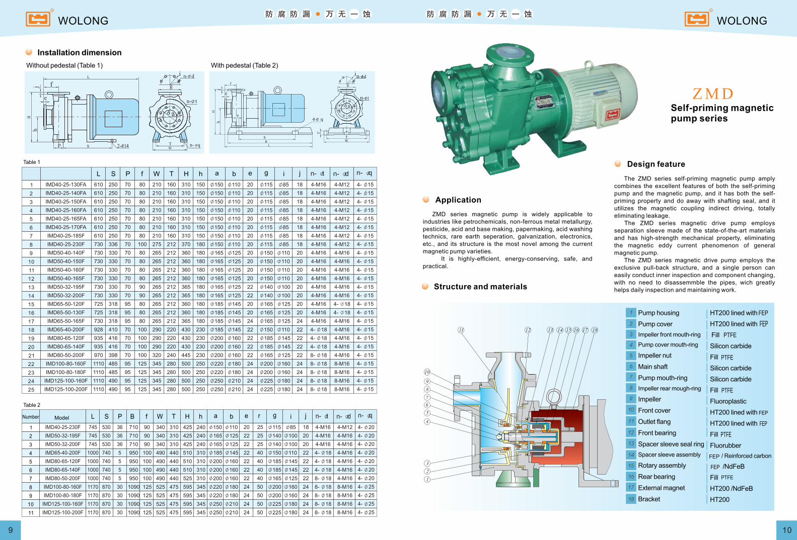
Installation dimension
Without pedestal (Table 1) With pedestal (Table 2)
Table 1
Table 2
ModelNumber
The ZMD series self-priming magnetic pump amply combines the excellent features of both the self-priming pump and the magnetic pump, and it has both the self-priming property and do away with shafting seal, and it utilizes the magnetic coupling indirect driving, totally eliminating leakage. The ZMD series magnetic drive pump employs separation sleeve made of the state-of-the-art materials and has high-strength mechanical property, eliminating the magnetic eddy current phenomenon of general magnetic pump. The ZMD series magnetic drive pump employs the exclusive pull-back structure, and a single person can easily conduct inner inspection and component changing, with no need to disassemmble the pipes, wich greatly helps daily inspection and maintaining work.
Self-priming magneticpump series
Design feature
Application
ZMD series magnetic pump is widely applicable to industries like petrochemicals, non-ferrous metal metallurgy, pesticide, acid and base making, papermaking, acid washing technics, rare earth seperation, galvanization, electronics, etc., and its structure is the most novel among the current magnetic pump varieties. It is highly-efficient, energy-conserving, safe, and practical.
Structure and materials
Pump housing
Pump cover
Impeller front mouth-ring
Pump cover mouth-ring
Impeller nut
Main shaft
Pump mouth-ring
Impeller rear mough-ring
Impeller
Front cover
Outlet flang
Front bearing
Spacer sleeve seal ring
Spacer sleeve assembly
Rotary assembly
Rear bearing
External magnet
Bracket
HT200 lined with
HT200 lined with
Fill
Silicon carbide
Fill
Silicon carbide
Silicon carbide
Fill
Fluoroplastic
HT200 lined with
HT200 lined with
Fill
Fluorubber
/ Reinforced carbon
/NdFeB
Fill
HT200 /NdFeB
HT200
WOLONG WOLONG
FEP
FEPPTFE
PTFE
PTFE
FEP
FEP
PTFE
FEP
FEP
PTFE