imia wg paper 95(16) supercritical boilers · pdf file2.1 coal-fired power plant overview ......
TRANSCRIPT
IMIA WG paper 95(16) Supercritical Boilers
1
IMIA Working Group Paper 95(16)
Supercritical Boilers
49th Annual IMIA Conference – Doha, Qatar
Working Group Patrick Jennings – Hartford Steam Boiler, Chair Jeff Ashman – Charles Taylor Simon Dejung - SCOR Thomas Gebert - AXA Christian Kolbe – Miller Heekun Park – Samsung Fire & Marine Insurance Dario Popovic – Swiss Re Dirk Von Roth - SCOR Michael Shepherd - Starstone Stephan Lämmle, Munich Re – IMIA Executive Committee Sponsor
Tim Reckmann CC SA 3.0 https://commons.wikimedia.org/wiki/File:Kraftwerk_Westfalen_2013_02.jpg

IMIA WG paper 95(16) Supercritical Boilers
2
Contents
1 Introduction ............................................................................................................................................. 3
2 Design Considerations .......................................................................................................................... 5 2.1 Coal-Fired power plant overview ........................................................................................................... 5 2.2 Circulation ............................................................................................................................................. 5 2.3 Materials of Construction ...................................................................................................................... 8 2.4 Next Generation Materials .................................................................................................................... 9 2.5 Traceability and Quality Control .......................................................................................................... 10
3 Power Plant Equipment and Processes ............................................................................................. 11 3.1 Water chemistry .................................................................................................................................. 11 3.2 Steam Piping ....................................................................................................................................... 12 3.3 Pressure Relief Systems ..................................................................................................................... 13 3.4 Metallurgy In Modern Power Turbines ................................................................................................ 13 3.5 Fuel Handling ...................................................................................................................................... 14 3.6 Firing Systems ..................................................................................................................................... 16 3.7 Auxiliary Equipment ............................................................................................................................ 17
4 Operational Considerations ................................................................................................................ 19 4.1 Operation and Maintenance ................................................................................................................ 19 4.2 Controls ............................................................................................................................................... 20
5 Insurance Risks .................................................................................................................................... 22 5.1 Construction Risks .............................................................................................................................. 22 5.2 Operational Risks ................................................................................................................................ 25 5.3 Financial Risks .................................................................................................................................... 28 5.4 Machinery Breakdown Risks ............................................................................................................... 29
6 Claims Issues........................................................................................................................................ 30 6.1 T 24 Experience in Europe .................................................................................................................. 30 6.2 Damage vs. Defect .............................................................................................................................. 31 6.3 Maintenance while out of Operation.................................................................................................... 32
7 Underwriting Perspectives & Challenges .......................................................................................... 32
8 Conclusion ............................................................................................................................................ 33
9 Appendix ............................................................................................................................................... 36
10 Bibliography .......................................................................................................................................... 39

IMIA WG paper 95(16) Supercritical Boilers
3
1 Introduction
Coal is an important fuel for power generation as it is a widely dispersed resource, requires relatively low cost capital for extraction, and the technology required to convert coal to electricity is well established. As of 2011, there were almost 1,000 billion short tons of proven reserves of coal with recoverable reserves in 75 different countries (EIA, 2015). Coal’s dominance in power generation is rapidly changing however due to the threat that climate change is imposing and the world’s reaction to this threat. As an example, in November of 2015, it was announced that the members of the OECD have agreed to not use overseas financing for most coal-fired power projects.
The International Energy Agency (IEA), in their publication World Energy Outlook 2015 notes by 2040 coal usage in developed markets will decrease in all scenarios that they investigated, it will level off in China and the largest growth market for coal fired power generation will be India. As the growth of coal slows and other sources for electric generation increase, coal will still represent 30% of the market share for electric power generation by 2040. (IEA, 2015)
New higher efficiency coal fired power plants are and will continue to be built to reduce the amount of pollutants generated per MW of electric output. These plants will utilize technology known as Supercritical , Ultra-Supercritical and Advanced Ultra-Supercritical technology. The differences between the supercritical technologies are simply the pressure and temperature of the steam. The higher the pressure and temperature, the more efficient the power plant. While the plant of the near future may require a Carbon Capture and Storage system (CCS) or integrated gasified combined cycle (IGCC) to achieve emissions goals, this equipment is beyond the scope of this paper. The following table provides a general overview of typical pressures and temperatures of the future technology (Phillips & Wheeldon, 2011), noting that the terms ultra-supercritical and advanced ultra-supercritical are not a formal definition.
Subcritical Supercritical Ultra-supercritical Advanced Ultra-supercritical
Pressure (Mpa) 17 (typ.) >24 25-29 >30
Temperature (DegC) 540 540 600 – 620 >680
Max Efficiency (LHV Net) 38% 43% 45% >50%
CO2 Intensity (g / kWh) >880 800 – 880 740 – 880 670 - 740
Status of technology Proven Proven Current/Emerging Technology
In development/ Future
As the push for higher temperatures and pressures to increase cycle efficiency continues, there are new risks appearing in boiler technology that was considered mature. This paper will broadly
There is a drive for increased efficiency in new plants to offset the high carbon intensity of coal.
Table 1
IMIA WG paper 95(16) Supercritical Boilers
4
address aspects of coal fired power plants and discuss in more detail the latest and future trends in supercritical boiler technology. These new trends, primarily new material compositions, have led to recent large losses for large supercritical boiler projects and underwriters and engineers need to be aware of these risks to develop potential mitigation steps.
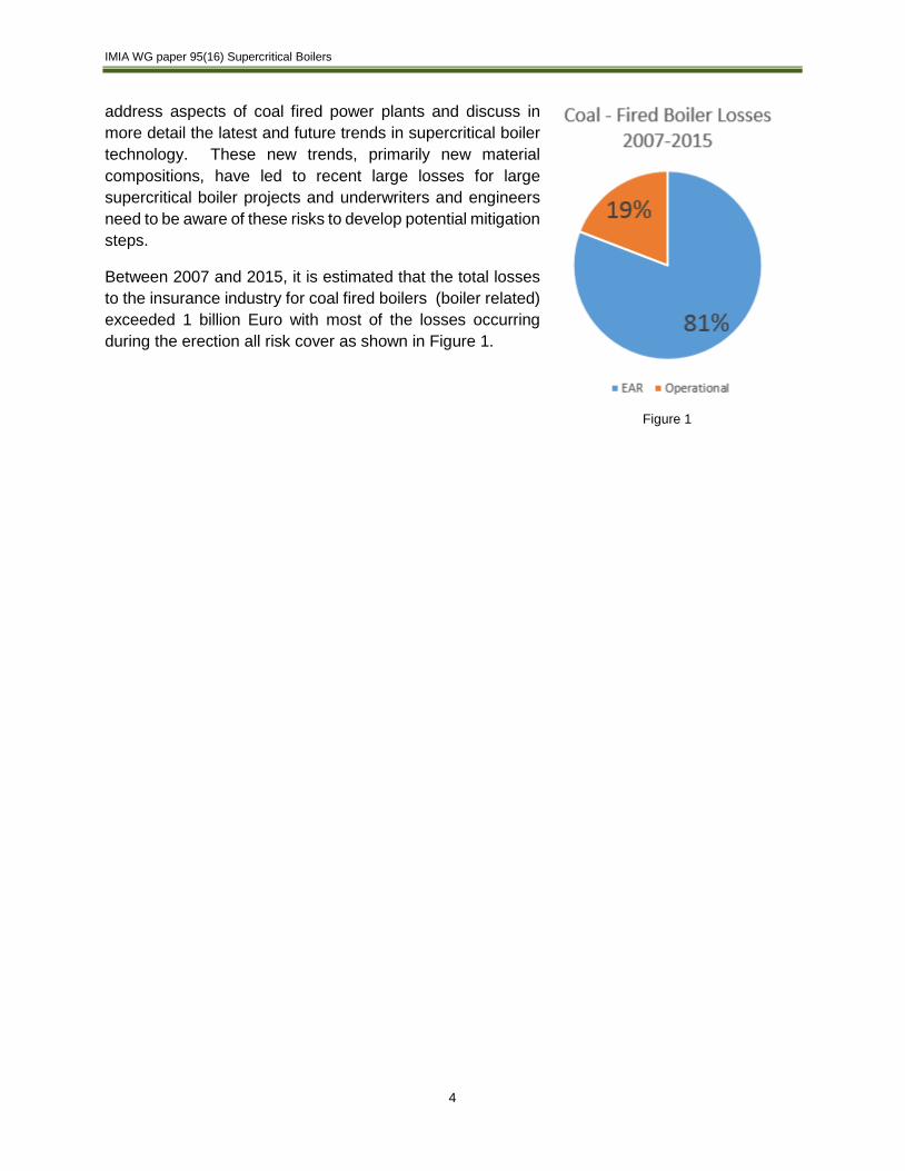
Between 2007 and 2015, it is estimated that the total losses to the insurance industry for coal fired boilers (boiler related) exceeded 1 billion Euro with most of the losses occurring during the erection all risk cover as shown in Figure 1.
Figure 1
IMIA WG paper 95(16) Supercritical Boilers
5
2 Design Considerations
2.1 Coal-Fired power plant overview
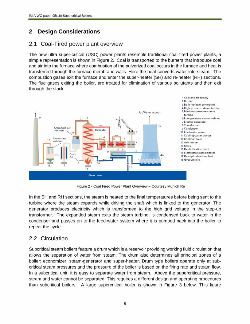
The new ultra super-critical (USC) power plants resemble traditional coal fired power plants, a simple representation is shown in Figure 2. Coal is transported to the burners that introduce coal and air into the furnace where combustion of the pulverized coal occurs in the furnace and heat is transferred through the furnace membrane walls. Here the heat converts water into steam. The combustion gases exit the furnace and enter the super-heater (SH) and re-heater (RH) sections. The flue gases exiting the boiler, are treated for elimination of various pollutants and then exit through the stack.
In the SH and RH sections, the steam is heated to the final temperatures before being sent to the turbine where the steam expands while driving the shaft which is linked to the generator. The generator produces electricity which is transformed to the high grid voltage in the step-up transformer. The expanded steam exits the steam turbine, is condensed back to water in the condenser and passes on to the feed-water system where it is pumped back into the boiler to repeat the cycle.
2.2 Circulation
Subcritical steam boilers feature a drum which is a reservoir providing working fluid circulation that allows the separation of water from steam. The drum also determines all principal zones of a boiler: economizer, steam-generator and super-heater. Drum type boilers operate only at sub-critical steam pressures and the pressure of the boiler is based on the firing rate and steam flow. In a subcritical unit, it is easy to separate water from steam. Above the supercritical pressure, steam and water cannot be separated. This requires a different design and operating procedures than subcritical boilers. A large supercritical boiler is shown in Figure 3 below. This figure
Figure 2 - Coal Fired Power Plant Overview – Courtesy Munich Re

IMIA WG paper 95(16) Supercritical Boilers
6
represents a typical hard coal-fired two pass design, common in North America and Asia while tower boilers are common in Europe.
At supercritical conditions there are no distinct boundaries between the heating, evaporating and superheating zones. In the evaporating surfaces of once through boilers, water is continuously and completely converted to steam. Once through boilers have no drum and the working fluid passes through the evaporating tubes only once. A once through boiler represents an open hydraulic system which means that boiler pressure is determined by the pump pressure.
In Combined Circulation Boilers, a back pressure valve is opened at start-up and the plant operates in the forced circulation mode. On attaining the specified load, the circulation pump is switched off and the back-pressure valve is closed automatically to run the boiler in the once through mode. Many SC and USC boilers operate in a sliding pressure mode to improve efficiency over the load range. In this operating mode, they will work between subcritical conditions at lower steam flows and supercritical conditions at higher steam flows. After the fluid exits the membrane walls, the flow through the SH and RH surfaces are similar to traditional units.

IMIA WG paper 95(16) Supercritical Boilers
7
Figure 3 - Supercritical Boiler - © Doosan-Babcock
Furnace (Membrane
Walls)
Coal Storage and Milling
SCR
FD Fans
Superheat Surfaces
Reheat Surfaces
Economizer

IMIA WG paper 95(16) Supercritical Boilers
8
2.3 Materials of Construction
The elevated temperatures and pressures of ultra-super-critical boilers require more advanced metallurgy than traditional supercritical and subcritical boilers. The first advanced material that came onto the market in the 1980’s was the Grade 91 called material. (Swanekamp, 2006) This is a ferritic steel with a high (9%) chrome content and other low quantity alloying material. This steel was shown to have increased strength at high temperatures which allowed for thinner designs in both tubing, piping and header material. This thinner design is desirable as it requires less material allowing faster start-ups and shutdowns as the stress occurring with heating thick tubing is much reduced. In addition, it is subject to less creep damage than traditional materials. Creep is long term damage over time due to operation at high temperatures and pressures. Grade 91 was different however, in that the metallurgy requires a very specific microstructure to obtain the desired mechanical properties. This microstructure is formed only under a specific heating and cooling treatment. If heat treatment is not followed properly during fabrication or welding, it will not have the strength or ductility that is expected and early failure may occur, even if the material passes visual and NDT inspections. When the first Grade 91 materials were used, issues were found related to improper welding and heat treatment.
In addition to Grade 91 materials, a new steel alloy called Grade 24 was developed to address the tubing require-ments of the water-walls (also called membrane walls) and it seemed ideal at first. This material, called T24 is a low carbon content, chrome-molybdenum alloy steel that includes micro-additions of titanium, vanadium, boron and nitrogen, developed in the mid-1990s by Vallourec & Mannesmann as part of the AVIF research project (Vallourec & Mannesmann Tubes, 2000). (Nowack et al, 2011) A related alloy developed at the time was Grade 23. In theory, T24 has good weldability properties, corrosion resistance, thinner wall diameters and higher creep rupture strength. This improves its mechanical properties against temperature and pressure, necessary for evaporators and super-heaters in ultra-supercritical steam generators. T23 and T24 with their low carbon content were thought to be able avoid the preheat and post-welding heat treatment (PWHT) steps during the fabrication and erection process. Unfortunately, countless leaks in most of the T24 containing steam generators suggest, that this assumption is not correct. The results are discussed in this paper. A cracked tube is shown in Figure 4. At this point, studies to better understand the
Figure 4 - T23 Tube Crack 10x M&M Engineering
IMIA WG paper 95(16) Supercritical Boilers
9
properties of T23 and T24 are underway and some mitigation steps have been identified during fabrication, erection, commissioning and operation. (Siefert & DuPont, 2013), (Bachez, Vyvey, & Peeters, 2014), (Bowe, 2013). The lesson to underwriters and engineers is that any material with a known issue that is used in a candidate project should be subject to scrutiny during the survey, risk analysis and UW process. Engineers should make themselves familiar with the current state of the art regarding the materials in use. First generation materials or those with a limited history should also be analyzed critically.
2.4 Next Generation Materials
As the temperatures in the boiler increase, the strength of steel decreases and as a result, the next generation of Advanced Ultra-Supercritical Boilers will require even newer materials and the application of these materials are in development now in multiple research areas around the world; in the EU under AD700 projects, in the US under the US Department of Energy, in Japan by the CEITP and in China by the Ministry of Energy, amongst others. As they are developed, these materials are being adopted in the codes of construction. At the highest temperatures, these new materials will be operated at temperatures in excess of 680°C. The following sections discuss where these new materials will be located in the boiler as well as identified needs of the material before they become accepted as suitable for boiler use. 1
In general, all boiler materials must have sufficient strength at the pressures and temperatures of the boiler component, resist creep (stretching of material under stress), and at the same time provide enough ductility to prevent cracking.
As a point of reference, a standard 600 MW electric coal-fired boiler may contain 200 km of tubing. This tubing is distributed in the membrane walls which directly absorb the heat from the furnace, the super-heater and reheater tubing, which heat the steam to the final turbine inlet temperatures, and the economizer, which heats the incoming boiler feed-water.
Membrane Walls:
For state of the art steam generators with steam temperatures of about 600°C, ferritc materials like Grade 24 can be used for the membrane walls. With material temperatures of 550°C at the membrane walls however the limit of ferritic material is reached. For higher material tempera-tures of a 700°C of steam generators (Advanced Ultra-Supercritical condition) martensitic materials like VM 12, another high chrome ferritic steel and T 92 are possible answers.
There are potential issues with these materials, such as steam side oxidation and it is possible that nickel base alloys like Alloy 617 (modified.) will have to be used. The manufacturing process for membrane walls of both martensitic materials and nickel base alloys still has to be qualified. This includes the qualification of the welding materials, non-destructive testing of the welds and bending tests of a membrane panel. A suitable process for the heat treatment of the large membrane panels has to be developed. For the nickel base alloy, Alloy 617 (mod.) heat treatment after welding does not appear to be necessary. From a manufacturing point of view this makes
1 For a list of current common and potential materials in boilers, see the appendix
IMIA WG paper 95(16) Supercritical Boilers
10
the use of Alloy 617 (mod.) for the membrane walls favored over the ferritic materials. (Meinberger & Laurs, 2012)
Superheater and reheater tubes:
In the low temperature ranges of super-heater tubes, standard ferritic materials can be used. As the material temperatures increase to 550°C materials such as VM12 and X20CrMoV12-1 will be applied up 600°C steam generators. As the temperatures exceeds the maximum allowable temperature for martensites of 600°C, austenitic materials like Super304H or HR3C need to be used. In a 700°C-Power Plant the material temperatures at the final stages of the super-heaters of more than 700°C are too high for the common austenitic materials.
Possible new materials for this temperature range are nickel base alloys like the modified Alloy 617, Alloy 740 and Alloy 263 and the newly developed Japanese austenitic material HR6W. For these new super-heater materials the qualification of the base material, creep tests across the weld and bending tests have to be carried out. The qualification of the base material which is a fundamental step on the way to a marketable product for most of the above mentioned new materials is still ongoing. Note that due to material properties, some materials may not be suitable for both the thick wall components (headers) and the thinner wall tubing.
Economizer
As the economizer is operated at the lowest temperature of the boiler, no special or newer materials are required.
2.5 Traceability and Quality Control
The increasing steam temperatures and pressures in the latest AUSC boilers have brought about the need for new materials discussed in this paper. There are a number of aspects that need to be considered for the use of these new materials in AUSC boilers to ensure that boilers of acceptable reliability and availability are provided. The main aspects are welding and heat treatment of high grade and dissimilar materials, welder training/certification and the use of a comprehensive quality control system.
The boiler manufacturer should ensure that there is full traceability of the material to a reputable, internationally accepted mill. It should be confirmed that the manufacturer of these new materials is also the mill. The boiler manufacture should have a comprehensive Positive Material Identification (PMI) scheme in place to confirm that the materials being received from the mill is made up of the components that they have specified.
Welders should be specifically trained and qualified using these new materials and consumables. Welding procedure qualification tests should be carried out using the appropriate filler material; hardness tests should also be included. Hardness testing of the base material and weld material after any heat treatment requirements should be carried out to confirm acceptability within the approved limits.
Weld specifications shall contain all of the required quality controls, including qualification, preparation, fit-up, preheat, weld consumables, welding sequence and post weld heat treatment.

IMIA WG paper 95(16) Supercritical Boilers
11
The welding specification will also contain requirements for testing and inspection, including visual examination, non-destructive testing (NDT) and hardness testing of all critical steam and water joints.
Non-Destructive Testing (NDT) – All welds have flaws or discontinuity, these discontinuities are interruptions in the normal crystalline structure (or grain) of the material. These discontinuities are not always defects. The purpose of NDT is to determine the size of any discontinuities. If these discontinuities are too large or are repeated too often within a weld then these welds can become defective. These defects will compromise the strength of the weld. There is a number of NDT analysis techniques available to evaluate the properties of austenitic materials and their associated welds. For an accurate analysis, NDT must be performed by appropriately qualified personnel.
Some of the newest NDT methods include phased array and Time of Flight Diffraction. The phased array and TOFD techniques allow for a three dimensional view of welds, in some cases this can replace the more time consuming RT techniques, which is a significant benefit as this allows for more welds to be inspected than traditional radiography with no downtime due to the radiographic exposure requirements.
3 Power Plant Equipment and Processes
3.1 Water chemistry
A large 1000 MWe plant operating in USC mode will use approximately 3,010 tonnes/hr of water through the boiler and turbine in a closed loop system, but there are requirements for make-up water during normal operation, or, if the unit has a leak and has to be shut down. Effective treatment or conditioning of water has made the use of more efficient steam cycles in the subcritical and supercritical pressure ranges possible. The higher the pressure of the boiler, the greater the need for purity of water.
Water used for generating steam for electric power must be treated to prevent corrosion, scaling and contamination of steam. The water quality necessary for a particular application is by convention related to boiler pressure, even though it is realized that the corresponding fluid temperature is the real factor influencing the reactivity of chemical and corrosion processes. The quality of the water used in the plant becomes more critical as the cycle advances from low-pressure industrial type boilers to high pressure utility boilers with supercritical boilers requiring the most stringent treatment guidelines. Some of the T24 issues were related to water chemistry. (Bachez, Vyvey, & Peeters, 2014).
As major causes of forced outages, internal corrosion and deposition cost electric utilities millions of dollars in repairs and lost availability. An effective water treatment program will have the following characteristics:
A comprehensive water treatment program based on the operating conditions of the boiler and source of make-up water is vital.

IMIA WG paper 95(16) Supercritical Boilers
12
• Develop and maintain a recommended water treatment for boiler water, feedwater systems and condensate polisher based on the pressure of the boiler.
• Control PH over the load range.
• Control oxygen concentrations in the feedwater to minimize corrosion and formation of pre-boiler corrosion products, which end up as depositions on heat-transfer surfaces in the boiler.
• Comply with operating procedures during start-ups, shutdown and outages to minimize corrosion and to avoid the entry of corrosion products into the boiler.
• Maintain boilers free from significant amounts of deposits by periodic chemical cleaning.
Under subcritical conditions, a variety of treatment options are available. At supercritical conditions, the standard water treatment is based on no solids being dissolved in the water, also known as All Volatile Treatment or AVT. Within the AVT, programs offer various options. From a risk perspective, the plant owner should be able to describe which treatment they use and why and they should document adherence to the parameters.
A careful review of sources of water and its conditioning is required to avoid economic losses because of slowdown in production, damage to equipment, and increased cost of operation.
3.2 Steam Piping
Conventional sub-critical boilers invariably incorporate one reheating of steam up to a final temperature at some suitable intermediate pressure. This same design principle has been adopted for USC and future AUSC boilers, however some designs incorporate a double reheating to further improve cycle efficiency. The material used in the high pressure (HP) steam systems needs to cope with the elevated steam pressures, temperatures and velocities. At the temperatures and pressures of current USC, Grade 91 material is often used. This material has good resistance to long term creep, but as noted, is a difficult material to handle, as it requires very specific heat treatment to maintain its mechanical properties. In the AUSC plants of the future, these systems will include piping made from one of the newer materials.
Bends and tees need to be kept to a minimum but sufficient to enable the pipework to expand and contract as the boiler is cycled. The material of the pipework needs to be able to handle the elevated temperatures and pressures of
Figure 5 - Steam Piping

IMIA WG paper 95(16) Supercritical Boilers
13
the superheated steam. When the boiler is on load the pipework will heat up near to the temperature of the superheated steam within it and suitable high performance insulation should be used.
From an engineering perspective, high energy piping should have a long term plan that addresses the setting of the hangers in the hot and cold position, inspecting the hangers and piping system regularly for correct expansion and monitoring the piping with a comprehensive NDE program based on the age and materials used.
3.3 Pressure Relief Systems
Pressure relief systems protect the boiler and piping from overpressure and they must be built to the applic-able codes. It is preferable to use hydraulically opera-ted safety valves to protect the high pressure section as well as the reheat section. In comparison to the use of conventional spring loaded safety valves the use of combined bypass and safety valves can dras-tically reduce the number of installed components. This will ensure that there is sufficient flow in the re-heater. A typical pressure relief design for an AUSC system can be seen in Figure 6.
3.4 Metallurgy In Modern Power Turbines
A complete discussion of steam turbine design and operation are outside the scope of this document, however, we do wish to point out developments for steam turbine materials that are part of the future generation of power plants. The two enemies of turbine metallurgy have always been corrosion and erosion. In turbines, these two conditions have the additional components of elevated heat and High Cycle Fatigue (resonance) that make appropriate metallurgy development a necessity.
For steam turbines, sub-critical turbines continue to operate in the 540°C region with a high degree of success in using high nickel-chrome alloys. However the industry is pressing to higher temperatures with supercritical turbines that are operating in the range of 600°C - 620°C and 29 MPa for much greater efficiencies. These machines require advanced metallurgy, not just for the
A high energy piping system maintenance program is key to avoiding long term issues.
Figure 6 - SH / RH Flow

IMIA WG paper 95(16) Supercritical Boilers
14
rotating blades, but also for the rotor shafts and the stationary components. Currently forgings of 9% -12% chrome with cobalt and boron have been developed for the USC market rotor forgings. While generally, the stationary components and most of the rotating components are designed to be replaced after a certain interval, the rotating core of these machines however is not considered a “wear and tear” item. At the high temperatures of the plant of the future, this may not be the case and these large rotating components may require exchange before end of plant life.
Unlike combustion turbine, large steam turbine rotors are typically fabricated from a single, very large forging (some weighing in excess of 250 tonnes). They are expected to last as long as the machine is considered economically viable. The material in the rotors go through large thermal changes and experience large radial and torsional loads. To make the most durable castings for the steam turbine rotors, extreme care is taken to control the molecular blend as well as applying proper heat treatment methods for the durability of the component.
In future plants, as the temperatures are increased to the 700°C range for the AUSC, additional metallurgical work will also be needed for the steam turbine components. Implementation of cooling systems, similar to that done in combustion turbines is an option for reducing peak temperatures and the amount of newer materials.
As for the boilers, nickel based austenitic alloys will be used in steam turbines, and there have been trial forgings of nickel based alloys for these applications. (Gandy & Shingledecker, 2013). The new materials will be needed in the casings, high temperature blade sections and in rotors. A development important for risk engineers to watch will be the use of dissimilar weld joints in rotors for the high temperature applications of the future. This dissimilar welded rotor design is notably different from the current practices of either a single large forged rotor or rotors fabricated of the same material.
These are examples of differences from the current design of steam turbines that create uncertainty and these aspects of future development should be followed by engineers and underwriters closely as the next generation of turbines is developed for commercial use.
3.5 Fuel Handling
The solid fuel most often used in power plants is some form of coal, and handling this fuel is the initial step in the “Power Generation” process. It is usually transported by rail; however some plants use road, barge, ship or a combination of all. There are plants that are built very close to mines and the coal is delivered directly by conveyor. Depending on delivery method and type of fuel, numerous kinds of fuel handling equipment is required. Fuel handling can be split up into the following categories, receipt, storage/reclaim, coal treatment and boiler feed. In addition to coal, the plant will have a start-up fuel, either gaseous such as natural gas or a fuel oil for light off. Natural gas will be piped directly to the boiler while other compressed gases will be stored on site. If used, oil will be stored on site to provide start-up fuel. Risk surveys should address adherence to the appropriate handling of the start-up fuels.
IMIA WG paper 95(16) Supercritical Boilers
15
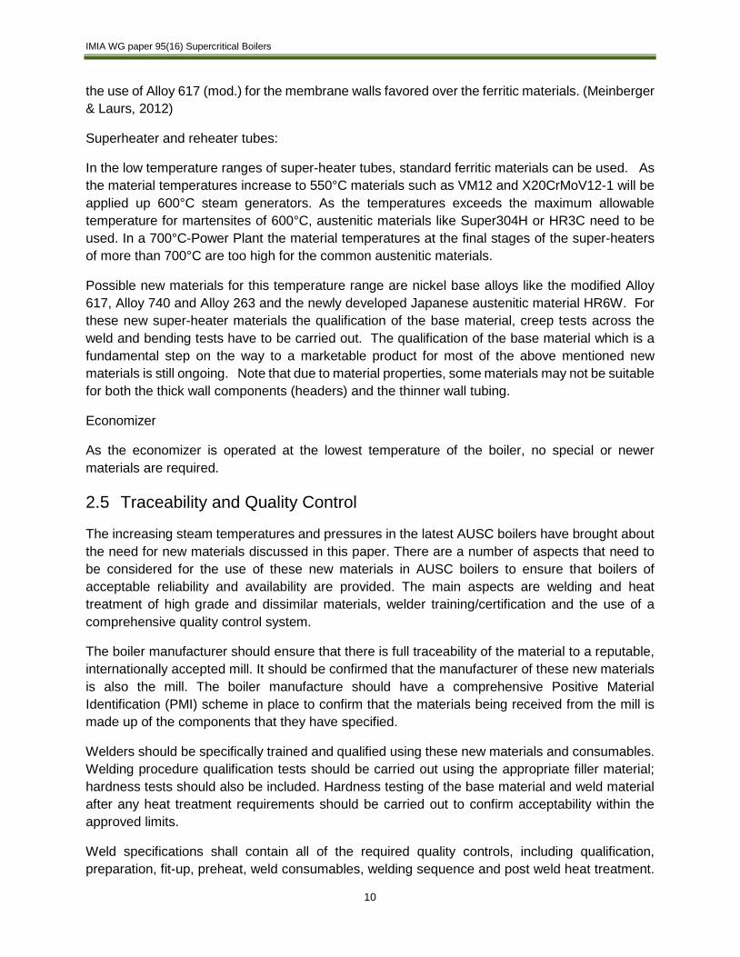
Receipt - Coal
Rail is the most commonly used supply method. Long trains of either bottom or rotary dump wagons are used. The train moves slowly and the coal is “dumped” into a bunker below as shown in Figure 7.
Trucks for road delivery use a tipping rear body, and the fuel is either tipped over open grates in the floor and falls in to an underground bunker or it is tipped and stock piled. The trucks are weighed on arrival and departure, the fuel is also sampled upon arrival at site.
With ships or barges the coal has to be scooped from within the holds by special unloading equipment as shown in Figure 8.
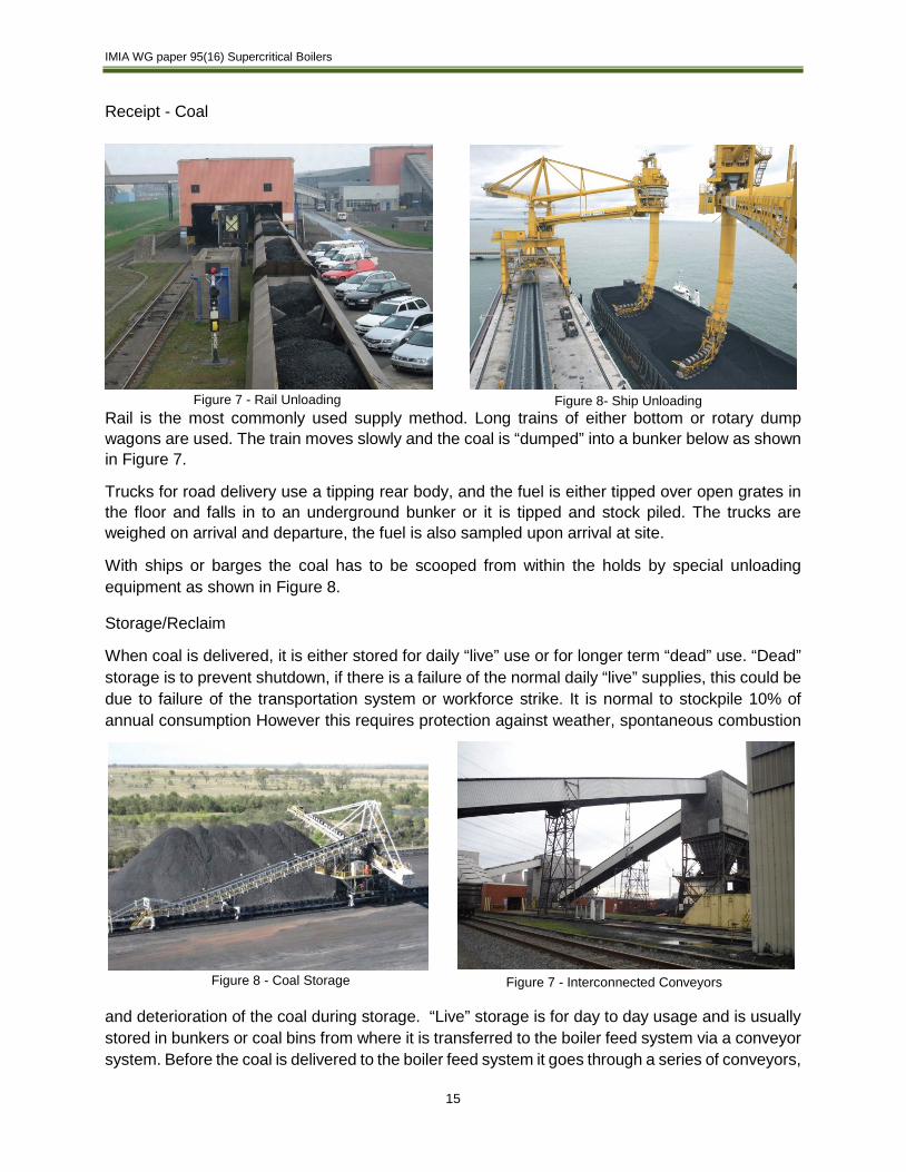
Storage/Reclaim
When coal is delivered, it is either stored for daily “live” use or for longer term “dead” use. “Dead” storage is to prevent shutdown, if there is a failure of the normal daily “live” supplies, this could be due to failure of the transportation system or workforce strike. It is normal to stockpile 10% of annual consumption However this requires protection against weather, spontaneous combustion
and deterioration of the coal during storage. “Live” storage is for day to day usage and is usually stored in bunkers or coal bins from where it is transferred to the boiler feed system via a conveyor system. Before the coal is delivered to the boiler feed system it goes through a series of conveyors,
Figure 7 - Rail Unloading Figure 8- Ship Unloading
Figure 8 - Coal Storage Figure 7 - Interconnected Conveyors

IMIA WG paper 95(16) Supercritical Boilers
16
separators, graders and crushers. Coal is fed into a series of magnetic separators to remove ferrous impurities. It is then passed through a series of graders where larger pieces of coal are fed into a crusher. The graded coal is then transported to the boiler feed system.
3.6 Firing Systems
Boiler Feed
Coal from the coal handling plant is fed, depending on the number of boilers via shuttle conveyors into boiler coal bunkers and from there into a mill for pulverizing. The feeder can be varied in speed to adjust the amount of coal entering the pulverizing mill and ultimately the amount of coal burnt in the boiler.
Coal enters the mill from the feeder and is ground to dust-like particles (75 microns), small enough to be blown to the burner front via the primary air. There is a number of different types of pulverizing mills, an example is shown in Figure 11.
Milling Plant
Temperatures within the milling plant tend to be in the region of 300°C to ensure that the coal is dry; this presents a significant fire hazard. There are a number of different detection/suppression systems. Carbon Monoxide detection is good for the early detection of burning coal. There are steam, CO2 and N2 inerting systems available for fire suppression, but this requires the mill to be shut down. There are systems becoming available to control all aspects of mill temperature using fine water spray and thus preventing fires.
There are two common types of firing systems. In the first, the coal and primary air is injected through the center of individual burners mounted on the front and rear walls. Secondary combustion air is provided through each burner and is mixed with the coal and primary air stream to form individually stable flames inside the furnace of the boiler. In the second system, the primary air and coal are injected from the corners at an angle towards an imaginary circle to create a rotating fireball. Secondary combustion air is supplied between the fuel and air and there are no individual flames.
In either firing system, an important aspect is the light off and stability of the burner to help prevent combustion explosions inside the furnace. In general, an igniter is used to initiate a flame that will then have to be proven in service by flame scanners. If the scanners do not indicate the presence of flame they will send a signal to the control room that will either “trip” (shut off) individual pulverizers or the entire boiler.
Figure 9 - Ball Race Mill

IMIA WG paper 95(16) Supercritical Boilers
17
Coal is not a uniform fuel, there are differences in the amount of energy as well as the ash contents and all boilers are designed for a specific coal type. Some areas of the world have a fuel of high moisture and low heating value called lignite or brown coal. Firing of lignite or brown coal requires a more complex design than described above. Due to the high moisture, the amount of heat required to dry the coal is much higher. This heat is provided from hot flue gases that are recirculated from the boiler through a hot fan back into the lignite pulverizers. These designs are more complex and operate at higher temperatures.
3.7 Auxiliary Equipment
The feedwater to a power plant passes a series of regenerative heating of condensate through a number feed water heaters. Those located before the boiler feedwater pump (BFP) are classed as low pressure feed heaters, while those after the BFP are classed as high pressure heaters heating water in steps up to the inlet of the economizer. This system is in essence similar to the traditional sub-critical plants and today with the exception of the pressure of operation. The steam for the regenerative heaters comes from the steam turbine extractions and the risk is that water will flow back from the heaters into the turbine. From an insurance engineering perspec-tive, implementing and maintaining a turbine induction prevention program will reduce this risk.
There is a large amount of equipment needed to run a coal fired power plant, and some of this equipment is a single source with no backup (1 x 100%) where others may be duplicate equipment that supplies a major amount of input (2 x 60% for example). This equipment includes the fans needed to supply air to the boiler and remove the flue gases as well as the pumps needed to supply water to the feedwater heaters or to the boiler. The large fans include the Induced Draft (ID), Forced Draft (FD) and Primary air (PA) fans and these can be either a single fan or a pair of non-redundant fans. The large pumps include the Boiler Feed Pumps (BFP) and the condensate
pumps. The BFP may be either steam driven or electrically driven while the condensate pump and the fans are all electrically driven. Complete replacement of these large pieces will exceed typical property and BI deductibles as the lead time for the equipment can be long. Often the plant will have critical spare parts, but it is rare to have a spare motor or rotor. This large equipment should be protected with appropriate fire protection on the oil cooling systems and vibration
Figure 11 – Steam driven boiler feed pump Hartford Steam Boiler
Figure 10 FD Fan Hartford Steam Boiler

IMIA WG paper 95(16) Supercritical Boilers
18
detection as appropriate. Other critical equipment related to the boiler includes the Air Quality Control System or AQCS.
The AQCS systems include equipment used to reduce the emissions pollutants such as particulate matter, sulfur dioxide (SO2), nitrogen oxides (NOx), acid gases and mercury. The major
equipment installed at any site will be dependent upon the regulations that are applied to the plant, but a typical new plant will have; Selective Catalytic Reduction (SCR), Flue Gas Desulpherization (FGD) and either a baghouse or electrostatic precipitator.
An SCR reduces nitrogen oxides by using a chemical reaction of the NOx and ammonia to eliminate the NOx. The ammonia is sprayed into the flue gas upstream of a large box containing the catalyst where the reaction occurs and the NOx is converted into inert products. The use of SCR systems are common on all combustion power plants.
An FGD plant reduces sulphur or other acids gases by using an alkaline solution, called a slurry that is sprayed into a tower along the flue gases. The reactant in the slurry reacts with the Sulphur to form a benign end product. In some locations, the product from the FGD system is utilized in building materials and is a positive cash stream from the plant. These systems can be either a wet or a dry system. Flue gas desulphurization is applied only to fuels with sufficient levels of sulfur to create the acid gases. This is predominantly the case on coal fired power plants.
Particulate emissions, also known as dust or flyash, is removed from the gases by either a baghouse system or an electrostatic precipitator. A bag-house, also called a fabric filter, consists of long, cylindrical bags located in compartments of the baghouse. Dust laden gases flow through the bags which capture the dust on the bags. An electrostatic precipitator ESP works by applying an electrical charge through the dust laden gases. This charge collects on the dust particles which are drawn to and captured on plates with an opposite charge. In both the baghouse and the ESP, the captured dust is collected and sent for disposal.
Auxiliary systems may have a single point of failure for a 100% BI event.
Figure 12 - Wet FGD – Babcock and Wilcox
IMIA WG paper 95(16) Supercritical Boilers
19
4 Operational Considerations
4.1 Operation and Maintenance
Competent operation and maintenance staffing and procedures are critical in any plant or industry, especially so in large complex environments such as power generating plants. Plant operators need to be trained in the operation of many inter-related systems while maintenance personnel have large complex machinery to keep running at high reliability. Dependent upon local conditions, differences in the availability of trained personnel will exist. In some markets, the soon-to-retire ‘Baby Boomer’ generation holds a wealth of knowledge and experience necessary to support the power system networks. This knowledge and experience needs to be passed on to the next generation of power engineers. However due to a number of reasons, there is a potential shortage of suitably trained and experienced engineers in the power industry.
The modern power plant control room has gone through significant changes over the last 10 to 15 years. Long gone are the days of large control rooms fitted with large boiler and turbine gauge panel boards, walls of instruments and chart recorders. Control rooms have now evolved into an almost office-like setting and automation and remote control have resulted in a decline in onsite engineers operators who have an all-around in-depth knowledge of the plant. There is still a requirement for high caliber engineers and operators to be on site and although they will predominantly perform a supervision type role over the control and interface systems, there needs to be a team on hand with the relevant expertise should an event occur that the control system is unable to respond to or should the control system fail.
One way that companies save costs is to cut back on personnel and reduce training expenses. To prevent a moral hazard, underwriters should understand the operating and maintenance strategy (e.g. redundancies) of the insured as well as the human resource philosophy about subcontracting services or keeping the know-how and workforce internally supported by training and education. The latter is more cost intensive but experience shows, that in the long run, motivation and continuity is financially beneficial and has a positive impact on technical issues, prevention measures and trouble shooting. Lack of commitment and experience has a direct impact on losses.
The cost saving pressure becomes also obvious when maintenance intervals are increased and planned outages are shortened. The result is often a “tower of Babel” phenomena: Many subcontractors, workers and operators fulfill simultaneously multiple, often interconnected activities during a very short period, including night and weekend shifts. To supervise all these activities and to manage the work permits is very demanding and is a potential source of bad workmanship and health and safety issues which can result in losses. These are not just myths; maintenance engineers have forgotten their tools when turbines were closed. It was realized obviously during startup.
The availability of critical spares and frequency and extent of preventive maintenance has to be defined. Processes and procedures, such as hot work permits or the use of computerized maintenance system should be followed. The idea is of course to do as little maintenance as possible but as much as necessary in order to prevent most failures and find hidden failures before
IMIA WG paper 95(16) Supercritical Boilers
20
they occur. Preventive maintenance is costly because you might change functional parts that might have worked for quite some time more. Therefore some utilities or individual plants, especially if cost constrained, have a strategy more towards run to failure. These losses end up in the insurance if not properly identified. Therefore it is crucial to have a maintenance clause in the policy
The above should all be addressed in engineering risk surveys; the organization, staffing (in-house vs. contracted), maintenance plans and procedures, critical spares, testing of automated trip systems, etc. so that underwriters can evaluate the risks.
4.2 Controls
The ultimate control of an ultra-supercritical power plant, boiler, turbine/generator and all auxiliary equipment is the duty of an operating shift that has the responsibility of operating the boiler in a safe, reliable manner. Due to the complexity of modern day power plants, they can only perform this duty with the help of integrated unit controls which include automated boiler controls. A boiler control system has two major functions, the first, and from an insurance perspective most important one, is the protection of the boiler equipment from accidents that can cause physical damage or injury. The second function is the operation and monitoring of the plant in an efficient, reliable manner. While manufacturers have their own trade names for these systems, generically they are called Industrial Control Systems (ICS) or Distributed Control Systems (DCS).
Boiler protection controls focus on those hazards that are particular to the boiler, including combustion hazards (fuel explosions), overheating or over- (or under)-pressurization of the boiler. These functions are accomplished by the use of controls like those for burners and fame control, safety interlocks, alarms and trips for protection. Safety interlocks work by requiring a series of steps with each action proven before the next step is allowed. As an example, before any fuel can be introduced into the boiler, the air fans must be proven on and proper draft established, minimum airflow through the boiler proven, air dampers are in the correct position and a minimum amount of air has purged the boiler. These steps are all designed to prevent accumulation of fuel in furnace that could explode when flame is first fired.
Alarms make the operator aware of a process value (such as temperature, pressure, flows or vibration) being under or over a design point enough to create a concern for either specific equipment or the process. Each alarm setpoint is designed to give the control room operator time to monitor or initiate a change prior to either an automated shutdown or damage to equipment occurs.
Boiler trips (automatic shutdown) are initiated when specific points being measured reach a predetermined trip setting. This system is designed to automatically and instantaneously trip the boiler when specific critical boiler conditions are met. For example, flame scanners monitor for the presence of a flame in the boiler. If the system detects no flame, a fuel trip occurs and the boiler is purged to empty the furnace of a potential explosion hazard. While it is important to trip the boiler before damage can occur, it is also important to avoid unnecessary trips as any shutdown and subsequent start-up represents a risk as well.
Common trip logics for ultra-supercritical boilers include:

IMIA WG paper 95(16) Supercritical Boilers
21
• loss of forced draft, induced draft or primary air fans (for single fan units, if dual fans than loss of both)
• combustion air flow low
• high or low furnace gas side pressure
• High boiler convection pass temperature
• High superheater outlet temperatures (usually this is a multiple point type trip)
• Loss or partial loss of flame
• Fuel shutoff (a total loss of mills)
• Low waterwall flow
• High furnace outlet steam temperature
• Turbine Trip
• Emission control equipment trips
• Manual Trip Function Initiated
Each jurisdiction will adopt standards for the design and operation of the burner management system (BMS), another name for the automated protection controls. The National Fire Protection Association (NFPA) 85, Boiler and Combustion Systems Hazard Code and the ATEX 94/9/EC are common standards. It is important that the designer understands the applicable codes as there are differences in philosophies in the implementation of these systems. In addition, a process for controlling access to the logic functions of the system are required so that only authorized personnel are allowed to change the logic inside the control system. Jurisdiction requirement may also include standards which address cyber security considerations.
In addition to the safety aspect, the control system is designed to operate the plant in an efficient and reliable manner. To perform this function, the boiler control system monitors the plant operation such as pressures, temperatures and flows and then based on those values and the load requirements, provide signals to control equipment such as fuel feed rate, fan speed, air dampers, spray station valves or other equipment to maintain the boiler operation within design standards while meeting the
steam flow temperature and pressure requirements to the steam turbine at the most efficient operating conditions. A typical control system for an USC power plant may have some 4,000 total data inputs and outputs to monitor or control a single unit.
Figure 13 - Control Panel Leitstand 2" by Steag, Germany - Steag, Germany. CC BY-SA 3.0
https://commons.wikimedia.org/wiki/File:Leitstand_2.jpg#/media/File:Leitstand_2.jpg
IMIA WG paper 95(16) Supercritical Boilers
22
5 Insurance Risks
5.1 Construction Risks
USC technology requires high pressure and temperature to achieve high efficiency and low carbon emissions. Higher temperature and pressure requires more robust material, precise design, and operational skill than previous super-critical technology. From Notice To Proceed (NTP) to Commercial Operation Date (COD) of USC coal fired plant, there are several factors to consider to assess risk quality.
Ground Conditions
The geological conditions for the plant are investigated extensively during feasibility studies to decide on plant location. Based on that, before construction, a further detailed geological survey and study is required for foundation design. Ground condition should be considered for choice of foundation to reflect bearing capacity for heavy equipment and rotating machineries. The foundation should be properly designed and constructed to support the heavy equipment and plant without subsidence, uneven settlement, and collapse. Design firms should be experienced in the areas and methods used. These risks are similar for both standard sub-critical and all super-critically operated plants.
Natural Hazard
Natural hazard risks are a high risk exposure during the erection and operation periods. Ultra-supercritical coal fired types require a massive amount of cooling water from sea or river. Water intake, and/or outfall structures construction involve wet works. In order to transport coal, a jetty might be included in construction work. Dredging, piping connections and backfilling work for water intake/outfall may be exposed to severe wave actions caused by wind storms or tropical cyclones. Wet work periods should be chosen based on the statistical record to avoid the season of tropical cyclones or winter storms. Recently, statistical data might not be enough for risk management due to extreme climatic phenomena such as flash flood and extreme cold weather which exceed expected statistical record.
For a plant in the Earthquake zone, seismic design is also to be applied as per the well-established national and international standards for design and construction. In case of earthquake during testing/commissioning period, all the critical utilities for control, monitoring, communication and emergency power backup should be protected and be operational by having a proper seismic design safety margin. Proper emergency preparedness procedure and training can reduce earthquake loss severity. Natural hazard risks are also the same for all pressures of boiler operation.
Transit
Erection all risks policies are usually extended for inland transit cover during land conveyance. And if it is further extended for DSU/ALOP cover, a small loss during in-land transit may trigger a
During the initial project discussions, it is vital that any new or relatively untested material or process is identified.

IMIA WG paper 95(16) Supercritical Boilers
23
large DSU loss. A transportation feasibility study should be done such as transportation routes, requirements for loading and unloading, adequacy of roads/bridges and transportation vehicles, and necessary permission from the authority.
Erection Work
Qualified welding processes are one of the critical aspects for successful completion of USC boilers because high-alloy ferritic/austenitic steel is used for furnace and superheater/reheater components. The boiler pressure parts must withstand the extra-ordinarily high temperature and
pressure (USC). Welding quality is critical to guarantee designed characteristic of tube for successful commissioning and operation, thus a very high standard of welding quality, control and assurance is required.
Heavy lifting is one of the key exposures during erection works. The rigging plan must be designed to not exceed lifting equipment’s design capacity within safety margin. Proper protocol needs to be assured for example, empty hook test and 3D base constructability review for heavy lift and wind impacts.
The erection needs is critical considerations for the new class of boiler materials. As the new, nickel based alloys are developed and eventually deployed, the welding procedures and quality assurance of these new materials must be vetted by the industry prior to wide scale application. In the insurance industry, there will [rightly so] be a certain skepticism of new boiler materials.
Hot testing and commissioning
The generation of energy in an ultra-super critical coal fired power plant takes place under extreme conditions. At the same time almost no plant is completely identical and often client requirements, building constraints and local conditions result in particular situations in respect of process flow charts and the fitting out. These circumstances require experienced commissioning staff and operators and suppliers with a track record regarding super critical power plants.
The commissioning and startup phases expose a plant to elevated thermal and mechanical stresses and uneven load conditions which result in an elevated loss exposure. During these challenging phases operators and commissioning engineers have to interact with the ICS-industrial control system (SCADA/DCS/PLC) which may need further calibration during the testing phases. Parts of an installation will run in manual mode - while part is controlled by the ICS - until a steady state of the process is reached and the plant runs in the specified continuous operation mode which is then normally controlled completely by the ICS, once the equipment set-points are determined and implemented. During the commissioning process, prior to all of the alarms being properly set, it is very common to have a large number of alarms, and critical alarms may be missed by personnel overwhelmed with the number of alarms. This “alarm flooding” has been a component
Erection work must be monitored vigorously for quality assurance of welding.
The hot commissioning and early operation phases present a high risk for insurers.
IMIA WG paper 95(16) Supercritical Boilers
24
in large losses and it is vital that the commissioning staff have an understanding of how they will handle this situation.
Hence, the ICS is a crucial component during start up and commissioning and underwriting information should contain information about the experience of the ICS supplier and its commissioning procedure and the involved staff. While there are standards that address the operation of the boiler, as discussed earlier, there are additional standards that address the design and installation of the Safety Systems. Applied standards, mostly the European standard IEC 61508 “Functional safety of electrical/electronic/programmable electronic safety-related systems” and IEC 61511 “Functional safety - Safety instrumented systems for the process industry sector” are used - IEC 61511 is equivalent to the American standard ANSI/ISA 84. As noted, the increasing complexity and interconnectedness of equipment presents cyber risks.
During testing and commissioning period, the installation and functioning of equipment should be proved to ensure safety and reliable operation. Each individual components should demonstrate to be functional, complying all design requirements.
Hot testing and commissioning means running of plant, machinery and/or component parts under load or unload by use of feedstock to simulate working condition. But, hot testing and commissioning does not mean dry running such as mechanical, hydrostatic test done before the hot testing and commissioning starts.
The hot testing and commissioning stage is considered to be the highest exposure during the entire period of insurance due to introduction of fuels and electric power in all areas with its high possibility of fire/explosion and/or machinery breakdown. For a coal fired power plant, the commissioning sequence need to be understood to assess insurance coverage. A project schedule needs to be provided and checked for example the first firing and steam admission, the point in time, when testing and commissioning terms of the contract works insurance policy apply.
Combustion controls need to be calibrated based on the coal quality. In case of design faults of tube and/or combustion specification, superheater, reheater and other heating surfaces can be overheated. To prevent fire/explosion due to CO gas in coal feeding and storage system such as coal silo (surge bin), and conveyer system, NFPA 850 recommends to install CO detector in the storage system.
Period of hot testing and commissioning exposure is dependent on the condition of hand-over to the owner. Functional, performance, and reliability tests may fall into the commercial operation phase which is the owner's risk except of maintenance liabilities left with the contractors. Strict hand-over conditions are beneficial to the owner, specifying clearly risks transferred from EPC contractors (and their insurers) to the owner.
Design cover under LEG or DE clauses also needs to be considered carefully, because defects of material, workmanship, design, plan or specification can cause significant loss or damage. Ultra-supercritical boilers and/or steam turbine machinery may have a bigger exposure due to defective or insufficiently proven material such as T24 and/or bad workmanship such as low welding quality than non-USC plants. See the claims issues section for further discussion.
IMIA WG paper 95(16) Supercritical Boilers
25
For further insight into aspects of hot commissioning and testing, please see IMIA WG paper 82(13) “Testing of Engineering Projects / Plants following Construction”.
Early operation
In a multiple unit installation, at the time of commercial operation of the first unit, other units are still under erection and/or testing/commissioning. Erection insurance may include cover of early operation of power generation of completed units while other units are still to be completed. For this period, insurers are asked to provide both operational and constructional cover to the insured and the risk is increased. Well-organized project management is critical due to complexity of responsibilities and people working for a number of different employers specifically, when commercial operation and erection works and commissioning organization co-exist on the same site.
The first issues with the T24 cracking became evident during the early operation period of the boiler. It is this operational / maintenance period where welding quality issues may surface. When the newer classes of materials for AUSC will be introduced, this will also be a period of concern.
Maintenance Period
EPC contractors and/or equipment manufacturers are obliged to provide maintenance service after hand-over / date of commercial operation. Loss or damage having its cause during construction period and/or loss or damage caused during maintenance work by the contractors is indemnified by extended maintenance cover. These risks include damage that may show early, such excessive erosion, corrosion, cracks and/or fatigue from the operation during the maintenance period as well as incorrect combustion / contractor related operational damage such as overheating, furnace explosion or implosion. Generally, the risks due to operator error or improper set points decrease over time as the operator’s skills improve and the operational feedback is implemented into the controls and operation.
5.2 Operational Risks
Fuel Handling
There is a number of risks present when handling and storing fuel. The following National Fire Protection Association standards set out guidance to help mitigate these risks; NFPA 8503, NFPA 31 and NFPA 58
Coal
Spontaneous combustion or self-heating of coal is a naturally occurring process caused by the oxidation of coal. This poses a problem when storing coal for longer periods of time, especially when it is exposed to the elements as this can accelerate the process. It is vital that coal stocks are well managed on a first in first out basis and closely monitored for hot spots. This can be done using thermal imaging infra-red cameras. Spontaneous combustion is also a problem when coal is stored in silos/bunkers and early detection is vital. This can be done using linear heat fire detection and/or monitoring for the build-up of carbon monoxide. Access to the interior of

IMIA WG paper 95(16) Supercritical Boilers
26
silos/bunkers is also important for fire-fighting purposes with access ports provided for the injection of fire-fighting agents.
Another ignition source is friction heat that is generated by the conveyance process. Rollers that support conveyor belts may jam or become stiff due to lack of lubricant or accumulation of dirt. The friction of the belt over the blocked roller can cause excessive heat. It is therefore essential to have a comprehensive routine/condition based maintenance program. Linear heat type detections systems can be used to warn of early overheating in this area. Thermal imaging is also a good warning method of conveyor overheating.
The dispersion of dust happens naturally as coal is being conveyed and a build-up of this dust can pose a significant fire/explosion hazard. A carbon monoxide (CO) detection system can provide an early warning sign of dust that is starting to heat/combust. Metal and rock in the incoming coal
supply can also generate sparks as it is being graded/conveyed. It has become common practice to protect conveyor belt systems with sprinkler systems; however activation of these systems requires a significant amount of heat. Systems are being developed using optical detection technologies like ultra-violet and infrared flame detection that will detect smouldering embers as they pass at speed on the conveyor and thus activating suppression systems before a significant fire breaks out.
Temperatures within the milling plant tend to be in the region of 300°C this to ensure that the coal is dry; however this also presents a significant fire hazard. There are a number of different detection/suppression systems available. Carbon Monoxide detection is good for the early detection of burning coal. There are steam, CO2 and N2 inerting systems available for fire suppression but this requires the mill to be shut down. There are systems being developed to control all aspects of mill temperature using fine water spray and thus preventing fires.
For the Air Quality Control System (AQCS equipment), there are several risks to note. If a boiler is equipped with an SCR system, the system will require ammonia to operate. Some installations will use anhydrous ammonia while others will use an aqueous solution that does not have the
Figure 15 - Coal Silo Thermographic Image Figure 14 Fire fighting piercing lance -
Figure 16 - Conveyor Sprinkler

IMIA WG paper 95(16) Supercritical Boilers
27
exposures of anhydrous. An additional risk specific to a certain design is the flue gas desulphurization equipment, often called scrubbers. Large fire losses have occurred along with lengthy shutdown periods with this equipment. These fires can be the result of improper hot work procedures around these rubber lined vessels. Fire risks are also possible on plants that have an oil start-up system and bag houses. Procedures should be in place to avoid unburned oil collecting on the bags and inlet temperatures to the baghouse should be monitored and provided with trip points as appropriate.
Controls
An underwriter should check if commissioning engineers and operators follow an alarm philosophy based on alarm management standards. Widely accepted is the International Electrotechnical Commission standard IEC 62682 „Management of Alarm Systems for the Process Industries" based on ANSI/ISA-18.2 and combining EEMUA 191 “Alarm Systems: A Guide to Design, Management, and Procurement”, ASM “Alarm Management Guidelines” and NAMUR 102 “Alarm Management” defining an alarm management process.
These standards define the safety criteria and emergency requirements an industrial control system ICS has to fulfill, assessed by a hazard and risk assessment. The standards define how to simulate and document the functionalities and process logic steps of an ICS during the factory acceptance test (FAT). On site the ICS is tested during the site acceptance test (SAT) together with the installed instruments and actuators as initial step of the cold commissioning.
Key features of an alarm management process are:
• The intention to rationalize alarms and reduce their appearance on a level which operators can handle. During normal operation one alarm- , in emergency situation ten alarms every ten minutes should be achieved.
• Design of field devices based on alarm management philosophy
• Human-Machine Interface (HMI) design is based on alarm management philosophy
• Differentiation between alarms and notifications
• Alarms should be relevant and unique – no duplication
• Alarms are classified in a hierarchic way and the required response prioritized – three priority levels are recommended.
• Alarms are tested during FAT and SAT before going live
• Alarms are monitored and staff is constantly trained
Process control has evolved a lot in the last 30 years and became more sophisticated over time, integrating more actuators and measuring points and handling complex control loops. As a result, more alarms were created which could not be handled anymore in a systematic way by operators and commissioning engineers. In one large loss the controls contributed to the failure by allowing the
Alarm flooding during initial start-up or during unusual events can mask critical issues. A well designed alarm management system is key.

IMIA WG paper 95(16) Supercritical Boilers
28
water and fuel flow to become mismatched, thus the steam generator section overheated. It is essential to test and document properly fail safe logics and alarm interlocks during the factory acceptance test FAT and to have experienced commissioning staff on site to avoid disastrous manual interventions. Operators and commission engineers cannot cope with too many alarms at the same time, and only experienced staff may know which alarms they can ignore.
For ICS/SCADA cyber and network security standards please refer to the IMIA - 2016 WG Paper 98 (16) “Cyber Risk”.
5.3 Financial Risks
Delay in Start-Up (DSU) or Advanced Loss of Profit (ALOP) policies provides coverage to principal and/or lenders for financial losses due to delays in construction project caused by material damage occurrence.
The Insurers indemnify the Principal (owner) in respect of loss of gross profit actually sustained due to reduction in turnover and increased cost of working. In terms of coal fired power plants, gross profit includes fixed fees and sometimes debt service and/or take or pay exposures.
Fixed operation and maintenance (O&M) Cost
The cost item is an allowance for the fixed costs of maintenance of the equipment such as boiler, turbine as agreed for example the long-term service agreement (LTSA), additionally costs for employees of the plant. Both of these cost figures are to be suitably adjusted for the technology involved and the size of the power plant.
Debt services
State of the art thermal power plants such as ultra-supercritical requires massive capital financing. Often debt service is included in the total sum insured (gross profit). Debt service costs include interest payable and the scheduled repayment of bank credits (principal). In case debt service is included, a DSU trigger can cause a significant loss to insurer. (Parsons Brinckerhoff, 2011)
Take or Pay
The Principal may enter into long-term take-or-pay contracts for fuel suppliers. These arrangements represent an obligation for the Principal to purchase a minimum quantity of coal. In case of an interruption, the Principal either takes the minimum quantity of coal or pays a penalty. In this case, principal will want to transfer the risk to insurer by including “take or pay” into the DSU / ALOP cover.
Contingent Business Interruption
Also DSU / ALOP covers can be extended to cover delay arising from physical loss or damage to Property Insured at the manufacturers or suppliers premises for construction material or components, but also at utilities regarding power/water or fuel supplies from a mine required for the construction works or testing. Commonly coverage is only for fire, lightning, explosion, aircraft including articles dropped there from (FLEXA).
IMIA WG paper 95(16) Supercritical Boilers
29
Property Damage
Another consideration for USC plants is the difference in costs of material from standard boilers. The USC boiler has a capital cost that is substantially higher than the comparable subcritical boilers and thus reason of high repair/replacement costs..
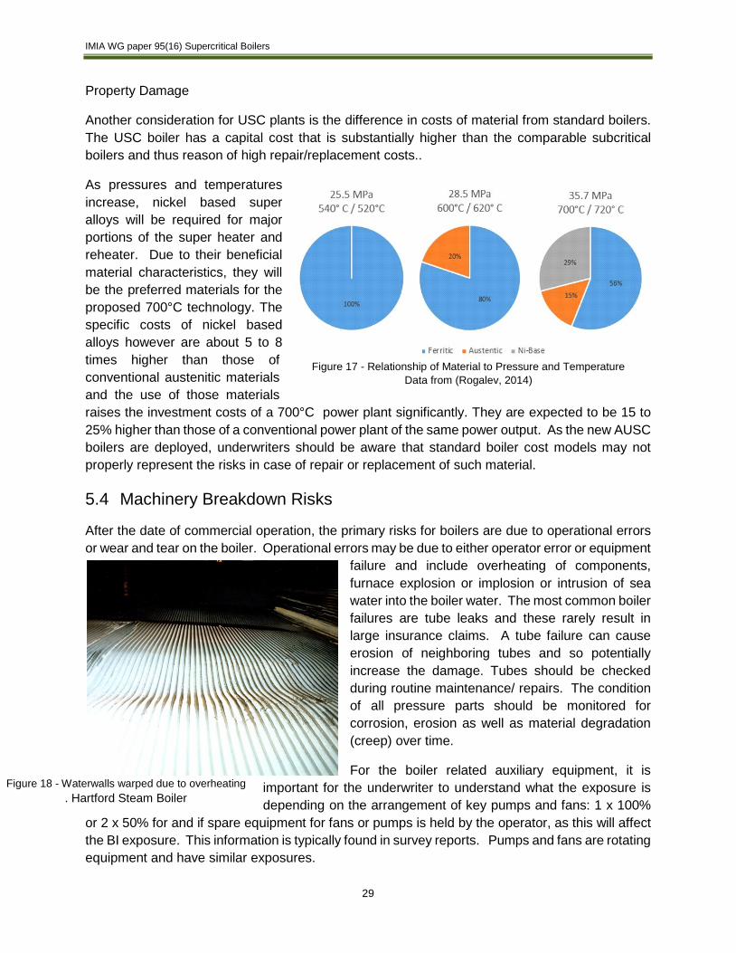
As pressures and temperatures increase, nickel based super alloys will be required for major portions of the super heater and reheater. Due to their beneficial material characteristics, they will be the preferred materials for the proposed 700°C technology. The specific costs of nickel based alloys however are about 5 to 8 times higher than those of conventional austenitic materials and the use of those materials raises the investment costs of a 700°C power plant significantly. They are expected to be 15 to 25% higher than those of a conventional power plant of the same power output. As the new AUSC boilers are deployed, underwriters should be aware that standard boiler cost models may not properly represent the risks in case of repair or replacement of such material.
5.4 Machinery Breakdown Risks
After the date of commercial operation, the primary risks for boilers are due to operational errors or wear and tear on the boiler. Operational errors may be due to either operator error or equipment
failure and include overheating of components, furnace explosion or implosion or intrusion of sea water into the boiler water. The most common boiler failures are tube leaks and these rarely result in large insurance claims. A tube failure can cause erosion of neighboring tubes and so potentially increase the damage. Tubes should be checked during routine maintenance/ repairs. The condition of all pressure parts should be monitored for corrosion, erosion as well as material degradation (creep) over time.
For the boiler related auxiliary equipment, it is important for the underwriter to understand what the exposure is depending on the arrangement of key pumps and fans: 1 x 100%
or 2 x 50% for and if spare equipment for fans or pumps is held by the operator, as this will affect the BI exposure. This information is typically found in survey reports. Pumps and fans are rotating equipment and have similar exposures.
Figure 17 - Relationship of Material to Pressure and Temperature Data from (Rogalev, 2014)
Figure 18 - Waterwalls warped due to overheating . Hartford Steam Boiler

IMIA WG paper 95(16) Supercritical Boilers
30
6 Claims Issues
6.1 T 24 Experience in Europe
Between 2005 and today, 14 coal fired ultra-supercritical (USC) plants (18 units) were built in the Netherlands, Germany and Czech Republic that had steam generators fabricated with T24. The hot commissioning of the first USC coal fired power plant in Duisburg Walsum (Germany) took place in 2010. After 400 hours of operation, the plant was shut down because of leakages at T24 welding seams. A root cause analysis identified the so-called hydrogen induced stress corrosion cracking (HISCC) as cause. Hydrogen is produced by pyrolysis with improperly dried welding electrodes and during acid cleaning of a steam generator. In addition, insufficient shielding gas atmosphere and uneven welding energy input, major problems when welding on site, create an oxidative microenvironment. Current losses suggest, that due to the presence of two water phase, evaporators are more vulnerable for HISCC than superheaters (Bachez, Vyvey, & Peeters, 2014) (Meinberger & Laurs, 2012). The leaking seams were repaired and the plant restarted. After 200 hours of operation there were again leakages and the plant had to be shut down again. It remained unclear how many of the welding seams which were repaired after the first event were leaking again. Accordingly it was not possible to decide whether a second repair of the welding seams would be successful and it was decided to replace the T24 in the evaporator section by the conventional material T12 (Court Decision LG Essen ). T12 does not allow the same operating conditions as T24 and therefore the overall efficiency of the plant was expected to be 2 % lower which has a significant impact on the feasibility of the plant. In addition, the replacement of a complete boiler section of that size is extremely expensive and takes more than a year. Cracks at the welding seams of the T24 evaporator membrane walls occurred in total on four plants. Details have been published for the losses at the Duisburg Walsum and the Boxberg plant only. But on all four plants, where leakages at welding seams were reported, the T24 was replaced by T12. That caused significant delays and cost increases, but it removed the uncertainty about the operational reliability of the evaporator section. The total delay of completion of the plants, where T24 has been replaced, was between 1.5 and 3 years.
Figure 19 - The drawing shows were the leakages at the Boxberg and Duisburg Walsum plant occurred
(Then, 2015)]
IMIA WG paper 95(16) Supercritical Boilers
31
Apart from the loss which is currently subject of a court case in Germany, it is unknown, if insurance claims were made under the erection insurance2.
6.2 Damage vs. Defect
Does the leaking of welding seams caused by stress corrosion cracking (without contributing other cause) constitute a damage which would trigger indemnification under the German EAR cover [AMOB]3? There is no clear answer to that question as there is an ongoing court case and a discussion among lawyers on that topic. The opinion of the court is that the successful completion of the pressure test constitutes that the boiler was in a serviceable state, and therefore the occurrence of leakages at the seams are damage and no defects. Accordingly at the first court instance it was decided that the claim is covered (Court Decision LG Essen ). The EAR insurer has filed an appeal, and therefore the final decision will take more time. An alternative opinion published by a group of lawyers (Langheid, 2016) is that the leakage at the welding seam is not a potentially covered consequential damage of a defect because the pressure test itself does not prove the actual functionality of the boiler as such. The welding of the seams took place in accordance with the generally accepted rules of technology (in this case a specification of the German government body). According to the specification a post welding heat treatment was not necessary, as the material thickness was not exceeding 10 mm. However, it has turned out to be necessary to carry out an effective heat treatment of the welding seams (Langheid, 2016). In consequence it remains unclear if the EAR insurance has to respond to the above mentioned case and it will be interesting to follow how the next court instance will decide. However a court in a different legislation might decide differently and that raises the question if the standard EAR wordings are appropriate to cover unproven technologies without a clear exclusion for the additional risk caused by the uncertainty. Furthermore the application of a new and unproven material in such large plants for the first time was taking an unusual risk that should not have happened. A meaningful test in a pilot plant should have been carried out including analysis how to weld and treat the T24 material successfully to achieve a reliable function of the equipment. Such developments risks are entrepreneurial risks and should be maintained by the contractor or boiler manufacturer who decide on the use of new technologies.
2 For additional references and details, refer to the table in the appendix 3 Allgemeine Bedingungen für die Montageversicherung or General Condition for Erection Insurance”

IMIA WG paper 95(16) Supercritical Boilers
32
6.3 Maintenance while out of Operation
An area of note for claims issues in long duration claims is the requirement regarding plant maintenance during a shutdown. Plant equipment must be protected during an extended outage to avoid future losses. This will require a written plan by the insured that addresses all equipment. The required measures will depend upon the length of the outage, the kind of material and kind of storage. As example, the boiler equipment and steam piping should be maintained under a protective nitrogen blanket to prevent corrosion during the outage. The steam turbine should be kept dry using a dehumidification plan along with regular equipment rotation and lubrication checks. Large rotating equipment (turbines, pumps or fans) will need corrosion inhibitors, rotating of the equipment and electrical checks along with uncoupling the motor for periodic runs. All systems should have a detailed plan including frequency of follow and a start-up plan for after the outage.
7 Underwriting Perspectives & Challenges
Large, long-lasting power and energy infrastructure projects are susceptible to environmental concerns, volatile fuel and energy prices. They depend heavily on governmental energy strategies and on political decisions. Coal is a CO2 intensive power generation process, not in line with UN’s climate targets, current energy supply is abundant and energy companies are in deficit. These technical, economical and geo-political exposures have to be taken into consideration when underwriting such risks.
The experience with T24 is a real case example of how entrepreneurial risks and prototypical material, fabrication processes and erection methods were transferred to the insurance market (Radevsky, 2010) (Schermutzki, 2012).
A new plant control system must be thoroughly vetted prior to operation. The first test is called Factory Acceptance Testing (FAT). At the vendor's location, tests are to be performed to verify that the system design functions as is intended. This test is most often witnessed by the contractor's engineer and/or the end user along with the equipment manufacturer's engineers. Further testing of the control system must be performed on site as the plant is being built and prepared for hot testing. These tests ensure that the entire circuit from the control panel to the device being operated functions as designed. It is vital prior to startup that all output signals to the control equipment are validated/calibrated prior to start-up. Proper management of any required changes and access to the equipment logic during construction is a vital part of a success start-up.
Alarm Management is another area of concern. Due to the ability to easily add sensors to equipment as well as the increase in the amount of equipment at a power plant, the number of measurements and related alarms has increased significantly over the years. During times of upset in systems operation there can be floods of alarms that can overwhelm the ability of the operators to understand and address the underlying issues. This can cause signals to be missed or misunderstood and accidents to occur. A well designed alarm system will rate alarms based on priority. The alarm screen must be cleared and under control before equipment start-up is permitted. Too often, “nuisance” alarms (alarms where set points are not correctly calibrated or if

IMIA WG paper 95(16) Supercritical Boilers
33
sensors are not the in proper position) are allowed to remain on the screen and not corrected/cleared. This creates confusion and operators will quickly learn to ignore them and when they are real in nature accidents will happen.
For new large USC plants a fully functional High Fidelity control simulator is a vital part of the start-up operation. The simulator has multiple purposes. First, a High fidelity simulator allows the operators to develop their ability and technical skills to fully operate the unit in a safe controlled learning environment where the operator can gain experience with unit upsets or emergency situations to correct those situations in real time without fear of compromising or damaging the actual plant equipment. The simulator can also be used by maintenance and engineering personnel to test logic changes or new control additions before implementation. Any changes to logic, including temporary logic jumpers (bypassing controls) should use a management of change procedure to document the process.
Underwriters must be aware of individual pieces of equipment that have the ability to create a BI interruption in auxiliary equipment.
There is a significant amount of experience in materials for the current USC market and it appears that most issues are known now regarding the newest generation of materials. It is important to observe that risk surveys address these known issues and that underwriters enquire technical details and understand the implications.
As the next generation of high nickel alloy or other materials are developed for both the boiler and the turbine, it is important that the lessons of Grade 91 and the Grade 24 materials are not repeated. Underwriters should keep updating their knowledge as experience and information become available and consider, how to clearly define unproven components or features and how far they wish to go regarding design cover to be granted.
While the above are new and evolving risks in the coal fired market, the “traditional” risks are still applicable. Fires due to the storage and handling of coal, furnace explosions due to fuel buildup, large critical equipment subject to equipment breakdown, deferred maintenance and operator error among others have not disappeared and must be guarded against and proper mitigations identified during the site surveys or mitigated in UW practices. As the financial pressures increase in areas where alternative and renewable sources of electricity are coming online, these risks will not abate.
8 Conclusion
Coal fired power plants have been a major source of electric power generation since the beginning of electrification, and the risks, while complex, have been known for many years. Recent losses in coal-fired power plants across various regions of the world have highlighted that this in general mature industry is changing. This change is occurring due to an effort to reduce the impact of coal on CO2 emissions via an increase in efficiency while trying to stay competitive. In addition, for existing plants in mature electricity markets, such as Europe and North America, the competitive marketplaces for fuel and renewable energy, are putting profitability pressure on existing power plants, including newly constructed USC plants.

IMIA WG paper 95(16) Supercritical Boilers
34
BACKGROUND
• Coal is an abundant energy source and will continue to play a large energy role in the world in the near future.
• To reduce the impact due to CO2 emissions and reduce operating costs, new plants will continue to be built utilizing Ultra-Supercritical (USC) technology and, as the technology develops, Advanced Ultra-Supercritical technology (AUSC) potentially with carbon capture.
• The shift of new coal fired power plants has moved from developed areas (North America and Europe) to developing areas
• Historically, turbine/generator and transformer losses have led the losses of coal fired power generation.
• Market forces, new materials, design and construction practices have led to large losses in boilers, particularly noticeable in EAR insurance.
EMERGING RISKS
• Emerging risks are showing in the marketplace that there should be an increased focus on Risk Surveys and Underwriting to identify potential areas of concern. Understanding the materials of construction and how they led to multiple failures may help avoid these risks in the next generation of Advanced Ultra-Supercritical power plants.
• Metallurgy
1. Higher temperatures and pressures have resulted in new materials being developed for the industry.
2. These new materials require scrutiny on the quality control procedures during the installation, maintenance and operational phases.
3. New materials grades should be vetted prior to their use, and the use of prototype materials or techniques should be highlighted for review by engineers and consideration by underwriters.
4. As plant operating temperatures begin to exceed 600 °C – 620 °C, new caution should be applied to the materials used.
5. Engineering underwriters and claims managers should remain aware of the issues related to the damage vs. defect issues. Engineering underwriters should stay abreast with the latest trends in the industry.
• Controls Systems
1. Alarm management is an area that is difficult to assess, but may have an important impact on losses. Surveys should address the question, how the alarms are managed.

IMIA WG paper 95(16) Supercritical Boilers
35
2. While not yet a source of large losses in the power generation industry, cyber risks are becoming an area of concern. Risk surveys and underwriting should address these issues by verifying that plant's management have established procedures for security based on appropriate standards.
TRADITIONAL RISKS
In addition to the emerging risks due to the new pressures, temperatures and market shifts, there are the traditional risk aspects to be considered.
• The main pieces of capital equipment in a coal fired power plant that, in the event of a loss, can exceed the policy deductible for property damage or business interruption are:
1. Boiler
2. Steam Turbine / Generator
3. Generator Step-up transformer
4. Flue Gas Desulphurization (FGD)
5. Coal Handling equipment
• There are traditional operational risks in coal fired power plants with established methods of identifying and addressing the risk. These risks are present in the construction, start-up and operation phases of the plant
1. Natural Catastrophe – Flood, Hurricane, Wind, Earthquake
2. Fire – Fuel and fuel handling, oil cooled equipment, FGD equipment
3. Equipment breakdown
4. Construction accidents
5. Operator Error
6. The Property and Machinery Breakdown risk surveys will help identify these traditional risks.

IMIA WG paper 95(16) Supercritical Boilers
36
9 Appendix
Likely Materials of Construction – SC, USC, AUSC
Material 1 Nominal Composition SC USC A-USC
Known Claims due to Material
Properties
Gr. 11 1 1/4 Cr-Mo ww 2
Gr. 22 2 1/4 Cr-1 Mo P, ww ww
T 23 2 1/4 Cr-1.5 W-V ww ww Y
T 24 2 1/4 Cr-1Mo-V-Ti-B ww ww Y
Gr. 91 9 Cr-1Mo-V-Nb-N P, SH/RH P, SH/RH ww Y
Gr. 911 9Cr-Mo/W-V-Nb-N P P, SH/RH ww
Gr. 92 9Cr-2W-V-Nb-N P P, SH/RH ww Y
Gr. 122 10.5Cr-W-Mo-V-Nb-N P ww
304H 18Cr-8Ni SH/RH
347H 18Cr-10Ni-Nb SH/RH
347HFG 18Cr-10Ni-Nb+process 3 SH/RH SH/RH
Super 304H 18Cr-10Ni-Nb-N-Cu+Process 3 SH/RH SH/RH
NF709 20Cr-25Ni-Mo-Nb-N-B SH/RH SH/RH
HR3C 25Cr-20Ni-Mo-Nb-N SH/RH SH/RH Y
Sanicro 25 22Cr-25Ni-Nb-N-Cu SH/RH SH/RH
HR6(7)W 23Cr-50Ni-7W-Nb/Ti P, SH/RH
617 Ni-22Cr-9Mo-10Co P, SH/RH, ww
230 Ni-22Cr-14W-2Mo P, SH/RH, ww
263 Ni-20Cr-20Co-5Mo-Al-Ti P
282 Ni-19Cr-10Co-8.5Mo-Al-Ti
740 Ni-25Cr-20Co-Al-Ti-Nb P, SH/RH
1 – Material – Materials may not yet be approved in jurisdictions. 3 - Processs - Thermal mechanical process used to improve oxidation properties 2 - ww - Waterwall Panels P - Pipes and Headers SH / RH - Superheat and Reheat Tubing Basis of Table -
"US Department of Energy and Ohio Coal Development Office Advanced Ultra-Supercritical Materials Project for Boilers and Steam Turbines, Summary of Results." Dated March 2011
"Lessons-learnt during construction, commissioning and start of operation" VGB Powertech Dated August/September 2015; Delhi, Mumbai, Hyderabad; Dr. Oliver Then.
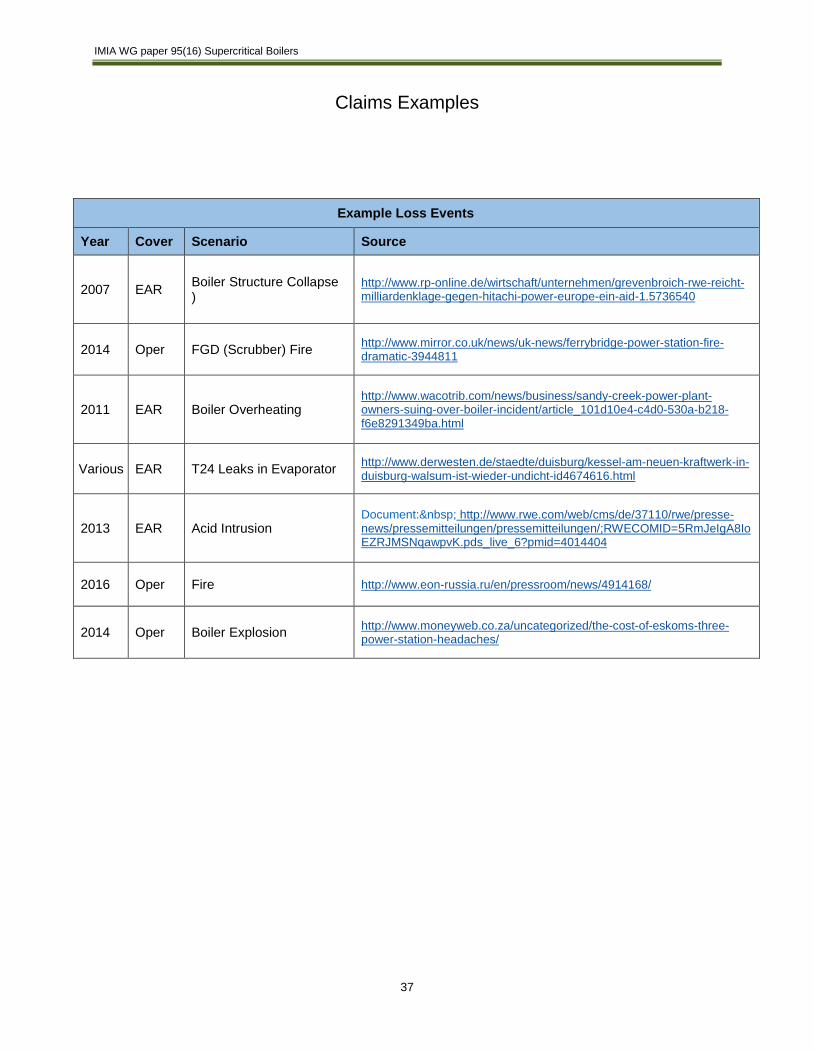
IMIA WG paper 95(16) Supercritical Boilers
37
Claims Examples
Example Loss Events
Year Cover Scenario Source
2007 EAR Boiler Structure Collapse )
http://www.rp-online.de/wirtschaft/unternehmen/grevenbroich-rwe-reicht-milliardenklage-gegen-hitachi-power-europe-ein-aid-1.5736540
2014 Oper FGD (Scrubber) Fire http://www.mirror.co.uk/news/uk-news/ferrybridge-power-station-fire-dramatic-3944811
2011 EAR Boiler Overheating http://www.wacotrib.com/news/business/sandy-creek-power-plant-owners-suing-over-boiler-incident/article_101d10e4-c4d0-530a-b218-f6e8291349ba.html
Various EAR T24 Leaks in Evaporator http://www.derwesten.de/staedte/duisburg/kessel-am-neuen-kraftwerk-in-duisburg-walsum-ist-wieder-undicht-id4674616.html
2013 EAR Acid Intrusion Document: http://www.rwe.com/web/cms/de/37110/rwe/presse-news/pressemitteilungen/pressemitteilungen/;RWECOMID=5RmJeIgA8IoEZRJMSNqawpvK.pds_live_6?pmid=4014404
2016 Oper Fire http://www.eon-russia.ru/en/pressroom/news/4914168/
2014 Oper Boiler Explosion http://www.moneyweb.co.za/uncategorized/the-cost-of-eskoms-three-power-station-headaches/
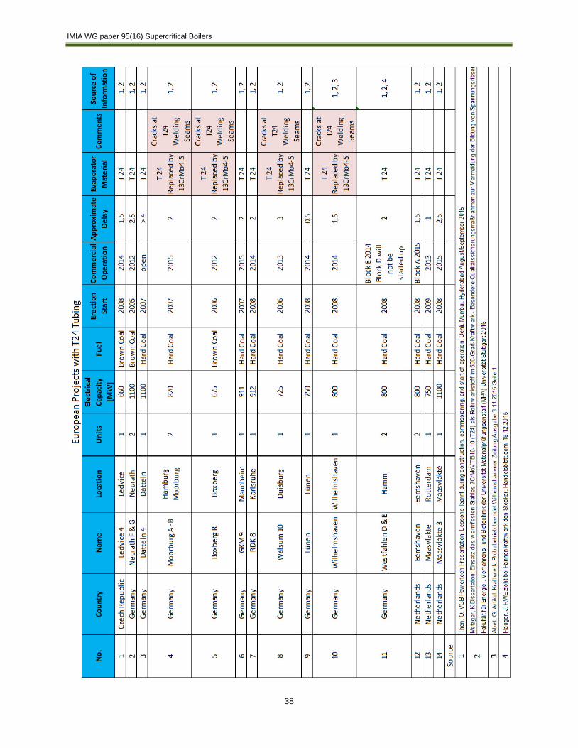
IMIA WG paper 95(16) Supercritical Boilers
38

IMIA WG paper 95(16) Supercritical Boilers
39
10 Bibliography Bachez, P., Vyvey, P., & Peeters, F. (2014, June 5). T24 Mitigation Measures taken at Coal Biomass
Rotterdam Unit 1. Power Gen Europe Presentation. Bowe, J. (2013). Modified commissioning procedure for USC boilers using material T24. POWER-GEN
Europe 2013. Court Decision LG Essen , 41 0 13/14. EIA. (2015). EIA International energy data and analysis. Retrieved 11 16, 2015, from Energy Information
Administration: http://www.eia.gov/beta/international/?src=home-f1 IEA. (2012). Technology Roadmap High-Efficiency, Low-Emissions Coal-Fired Power Generation. Paris:
International Energy Agency. IEA. (2015). World Energy Outlook 2015. Paris: International Energy Agency. Langheid, T. e. (2016). Der Werkstoff T24 in der Montagerersicherung - VersR 2016 No. 1. Meinberger, & Laurs. (2012). Handling of T24 steel in large Power PLant Steam Generators. London
Engineering Group Conference. London. Nowack et al. (2011). Quality Management at RWE using T24 steam generator materal as an example . Parsons Brinckerhoff. (2011). Electricity Generation Cost Model, Department for Energy and Climate
Change UK. London: Parsons Brinckerhoff. Phillips, J. N., & Wheeldon, J. M. (2011). Economic Analysis of Advanced Ultra-Supercritical Pulverized
Coal Power Plants: A Cost-effective CO2 Emissions Reduction Option? Advances in Materials Technology for Fossil Power Plants, Proceedings from the Sixth International Conference, (pp. 53-64). Santa Fe.
Radevsky, R. e. (2010). IMIA WGP 067 (10) Fast developing Technology. Retrieved from IMIA Knowledge Base: http://www.imia.com/knowledge-base/
Rogalev, N. e. (2014). A Survey of State of the Art Development of Coal-Fired Steam Turbine Power Plant Based on Advanced Ultrasupercritical Steam Technology. Contemporary Engineering Sciences, Volume7, No. 34, 1807-1825.
Schermutzki, B. e. (2012). IMIA WGP 077 (12) . Retrieved from IMIA Knowledge Base: http://www.imia.com/knowledge-base/
Siefert, J. A., & DuPont, J. N. (2013). Material Behavior of T23 and T24. Advances in materials Technology for Fossil Power Plants (pp. 513-524). Waikoloa: ASM International.
Swanekamp, R. (2006, February 01). Handling Nine-Chrome Steel in HRSG's. Retrieved from Power Engineering: http://www.power-eng.com/articles/print/volume-110/issue-2/features/handling-nine-chrome-steel-in-hrsgs.html
Then, O. (2015, August/Sept). Lessons-learnt during construction, commissioning and start of operation. Delhi, Mumbai, Hyderabad: VGB Powertech.
Vallourec & Mannesmann Tubes. (2000). The T23/T24 Book. Vallourec & Mannesmann.