municipal waste treatment plants - imia
TRANSCRIPT


Municipal Waste TreatmentPlants
Vincent Di Chirico
Contents
Preface 5
1 Foreword 6
2 Waste disposal through the centuries 8
3 Waste management in industrialised nations 173.1 Goals of modern waste management 173.2 Integ rated waste management 18
3.3 Waste production 203.4 Nature and composition of waste 22
4 Technical design aspects of a municipal waste treatment (MWTI plant 274.1 How an MWT plant operates 274.2 Thermal waste treatment 28
4.3 Basic stilges in the design of an MWT plant 314.4 Main processes available for waste incineration 354.4.1 Combustion grate furnace 364.4.2 Flu id ised-bed furnace 384.4.3 Rotary kiln 404.4.4 Pyrolysis fu rnace 424.5 Flue-gas treatment 444.5.1 Formation of pollutants in combustion gases 444.5.2 Polluta nt concentrations in untreated fl ue gases 444.5.3 Emission controls 444.5.4 Principal methods of flue-gas treatment 464.5.5 NOx reduction (denitrification) 504.5.6 Dioxins and furans 514.5.7 Outlook 524.6 Treatment of incineration residues and flue gases 534.6.1 Slag 544.6.2 Fly ash and dusts 544.6.3 Sol id residues extracted from the flue-gas scrubbi n9 water 55
5. Description of a municipal waste treatment plant 575.1 Structure of a conventional MWT plant 575.2 Description of principal equipment 585.2.1 Reg istration and storage of wilste 585.2.2 Inci neration fu rnace 595.2.3 Boiler and thermal equipment 635.2.4 Flue-gas treatment system 64
2

6 Waste treatment costs
6.1 Environmental technology
6.2 Waste incineration costs
7. Dangers and typical damage
7.1 Dangers in the construction, erection and operating phases
7.2 Dangers associated with the process
7.2.1 Util isation and handl ing of sol id products
7.2.2 Corrosive su bstances and environ mems
7.2.3 High pressures
7.2.4 Rotati ng machi nes
7.2.5 Fire and explosion
7.3 Typical damage
8 Engineering risks associated with the construction and operation of an MWT plant
8.1 Main forms of engineering insurance
8.2 Main project stages in the construction of an MWT plant
8.2.1 Civil engineering and building works
8.2.2 Erection of equipment
8.2.3 Commissioning the plant
8.2.4 Industrial operation
8.3 Comments on the business risks
8.4 Underwriting recommendations
8.5 Special clause
9 Glossary
10 Bibliography
3
676768
717174
7474767677
78
81
8181
82
838486868891
92
94

Preface
Envi ro nmen la 1po 11 u·
Il0rl IS one of the
worst side-effecrs ofthe rapid eco no micgrowth seen in thiscentury_
Liner, garbage, refuse. All these terms conjure upvisions of u nsighdy heaps of obnox.ious. foul
,'mdling waste:. Our oFsighr is our of mind, and
our consciences are soon appe:lsed once rhe rubbish, an unavoidable by-product of modern civil
isarion, is caned off elsewhere.
lndusrry and commerce generare vasr quantities
of waste. The more highly developed a socielY is,the more rubbi~h it produces. The higher the
poplllarion density, rhe greater che envirnl1mentalburden. In areas where there are only limiced
facilities for n<lwral waste disposal, rhe willing
nes,'. the need a.nd cvcn [he obligation to disposeof waste in a sensible: and environment;l.lIy sound
way is becoming more and more pres,~ing.
Political, soci21 and indllstrialleaders all
acknowledge that the problem exists, and arenow willing to cake up che challeng.e. The solucion musr be efJ-ectivo- and economical, buc envi
ronmenrally friendly as well, The tradition ofeliminating, desrroying and breaking down waste
through incineration goes hack many thousandsof years, bllf the development and refinement of
the req uired tech noJogics bas Oil II' really ad V;<o
ced over the last fcvv· decades, :w:em pti ng to
provide a solution to the problem of clean and
practical disposal of hnardous wasre produced bymodern civilisation,
However, there arc increasing c"Jlls for more envi
ronmellt:1l1y sound imralbrions rh at also s3risfyaesrhetic and cost/benefit requirements. Environ
mental technology companies are therefore under
constJllf pressure ro develop ;llllOvarive and
high-perfo rm ance processes.
5
This is \vhere the ch:111enge ro imure:rs begins.They muSt nor only be in a position to offer c1i
ems insurance cover to protect them from the
financial come(luences of losses, but they mustalso have sufficienr experience and know-how ro
play an active role in loss prevention.
This publication gives "J broad picrure of rhe
many differem facecs of wasce treatment. After
in rroducing the various aspects of waste management in indusrrialised nations, rhe author pro
vides a clear and detailed descriprion of the mosrcommon technologies currently used. He draws
on his extensive indusuial experience to highlight
rhe potelHial dangers inherent in the consrrllC(ion and operation of municipal waste rrenmenr
plams. This presenrarion is wunded off withobservations on the insura nce of technical risksand some pracrical underwriting advice.
By tackling (his extremely copical subject, we
hope (0 improve the understanding ot the way
1l11l1\icipal waste treatment (M \'\IT) pian rs opetate, and suggest ways of reducing or even avoiding loss e},:posu re.
Richard Gluckler
Engineering Departmenr

Foreword
Since the dawn of indusrrialisariol1 our socialconditions have consistently improved [0 rhepoiru where our marerialliving srandards arenow at unprecedented levels as we approach theend of rhe twemieth century. On tbe down side,one of the worst conseq uences of this progresshas undoubrcdly been the spread of pollution,whose impact has led to a disturbing dererioration in our overall q ualit)' of life.
In rhe p;J.,t, the intetests of indusrriJ.lisation andeconomic growth were in direcr conflicr wid) thepreserva ti 0 n 0 f na[u re. 0 urea nsu mer soc icry,with ics enormous energy demands, has finallyrealised, however, that our natural resources areneither inexhaustible nor durable. As it con tinuesto expand, industry is gradually paying moreattention to the environmem, both as regardsmore ef±1cienr use of energy and thc control ofhaLardous emissions.
Alrhough a return co narurc is obviously our ofrhe question, changing our behaviour is certainlyan imporram step rowards p reserving the environ men (. Environ mcntal prorection has becomean essential component in the management ofmodern society It is a basic principle which wemuse respecr in our behaviour and life Hyles.However, the path we have to travel to achieve abalance between sustainable economic growthand the conservation of [he environment is longand tortuous. Green policies should nor be synonymous wirh a slo\vdown in economic growthand industrial activity, but rarher encourage asearch for more efficient use of exisring finiteenergy resou rces and raw matcri;J!s.
6
However, avoiding pollution and hoping thatwasre producrion wi 11 be regulated merely by vi r(uc of individual awareness and through everyday enforcement of basic rules i~ not enough ropreserve our environrnen r for fu rure generarions.Mosr of rhe problems connected wi[h environmental protection can only be wlved wirh thehelp of modern, high-performance technologiesrhat also need ro be economically viable.
In the past, waste treatment plants wefe suspected of bei ng a major sou rce of pollmion - q LJ itejustifiably, in some cases. Since rhe introducrionof Stricter environmental comrols, the design ofthese plalHS has advanced enormollsly, however,and they have now becomc J means of environmental protection, since they allow us to disposeof the rnoun rai ns of wasre we produce clai Iy in anecologiGllly responsible way.
In (he past the usual rerm was municipal wasteincinerarion (M\'V'I) plant, but now;Jdays it ismore common to encounrer names such as wasterecycling cenrres (WRC), Illunicipal wastc ([catmem (MWT*) plant~, or sometimes refuse to
energy systems. These (enns refien (he newambitions of this technology wi rh in rhe contextof integrated waste management programmes.
~ \of\XiT J<; rbe- rerm u~Ld III Ih 1$ publlCHio n

The aim of thi~ puhlication i, to provide a globalview of the problems associated wirh the manageOleIH and thermal uealllle))( of waste in iJldusrriaJised coun tries. Our goal h;:js becn to provide aninsigh t in[Q the tcchnologies available in mu nicipal waste treatment without excessive technicaldetail. We have consciously avoided includingscienrifJc form u lae or mathemarical models, to
make the con ren r e;lsier to digcsL
This puhlicJtion is divided into three sections. Itdescribes the problems presented by the thermaltreatluelU of waste in ind.llstria Iised countries,from a technical, environmenwl and insuranceVI ewpoJJl t.
The hrSt section provides an in (reduction to thehistory of \-vaste cl isposal over the centuries: Howhas rhe production of wastc and its characteristicscvolved over time? We also look ;tt the objectives
of modern waste management and rhe new roleplayed by MWT plants in our sociecy.
The second ,eCtion looks at [he technical designaspens of the MWT plant. There is a briefdescti ption of Hied and tested processes ;ll1dtechnologies. Readers who wam to find out moreabout the individual components that make upan MWT planr and how they [unction will alsofind useful information here.
7
The third sectioo examines the insurance of engineeri ng risks associated \vi rh rhe constrUCtionand operation of an MWT plant. The description of rhe various consnuction stages and rheplant's commissioning, as well as the potentialdangers during these periods, is intended to
make underwri rers more aware of rh is category ofbusi ness in their risk analysis and prem it! m ratingapproach.
\VJe wish to thank all the companies kind enoughto provide us wirh their specialised publicationsand photograph ic matcrials. rn pa rricu lar wewish to thank Von Roll EnvironmelHal Technology, Zurich, \'V'idmet & Erost Environmental
Technology, Zurich, Delltsche Babcock ill Krefeld, Germany and the Machinery Loss Prevention Service (MVD) of the Swiss Associarion oflechnicallnsurers (SVTV) for their concribution. We would also like to extend our sincerethanks ro everyone \vhose hard work and inputhelped to hring this documem into prinr.

Waste disposal through the centuries
Ancient TimesArchaeological excavations 011 the 6itcs of ancient[Owns around the Mediterranean and in theIndus valley h;lve shown chac many rowns hadrheir own sewerage ~ystems. In Crete, for example, dirches were dug ro Store solid wasre andwere emptied as required.
In Egypt and Greece human excremenr was putin eanbcnware pars, presumably to be used asfertiliser on the fields, alrhough [here is no evidence to prove this. The Roman!> channelledclean dr·lnking wafer over long diStances to supply cO\vns, and siphoned orT wasre water rhroughdrains leading into the "c1oaca maxima", theIII a! n sewer rhar was laid along the bed of a ri ver,into which the effluent was even (lJally discharged.
Alrhough palaces and public buildings whichalready had toiler facilities were connected [0 thesewerage syStem, {he same was nor true of privarehouses: rhey had to collect rheir waste and excrement in earthenware pots which slaves wouldthen empty intO the drainage canals.
After the Roman Empire was overrun by (heGermanic tribes, the sanitation sysrems graduallydetcriorated. The drains were /10 longer cleanedout and clogged up. Emuent began to seep omin to the streets, causing a rerrible Stench. Onedircct comcquence of chese conditions was the
spread of the plague.
Power and powerlessness in the Middle AgesIn che Middle Ages, the grear barons in their forI illed casdes disposed of food scraps and Otherrcfuse simply by throwing them over Lhe castlewalls. Thi~ is on~ reason why castle moacs arcsuch valuable arch.aeological sites. But JUSt im;tgine the smell!
The situation in the towns was hardly any berrer:people simply dumped their rubbish on rheStr~ets.
8
A reporr on Paris in rhe eleventh centuryde~cribes this sordid siru3rion: fIlrhy, pot-holed,unpaved streets, permanendy covered in excremen rand Jinec, no domestic sanitation sysrems,so that WJste wacer sim ply collecred in sragnantpools on rhe streets, addi ng ro che generalsqualor.
One swry illustrates just how bad things were:Phjlip II Augusrus, king of France, "vas watchingheavily laden vehicles pass in front of the palacewindow. The weight of the convoy stirred lip chefoul cocktail of excrement and rubbish on thescreecs, and the Stench W<lS so overpowering thatthe king fainted. He W;lS so shocked that heordered all the streets and squares around thepalace to be meralled.
Although this is an example of the authoriticsin chis case the kil\g of France - man;tging cosuccessfully improve the hygiene scand<Jrds of dletime, it was very much che exception racher thanrhe rule.
14th and 15th centuriesFor the first rime an edicr issued by the Provostof Paris ordered aU citizens to cake their waste to
sices specifically set aside for this purpose. Theauthorities stepped up the! r efforcs, and saw [0 itrhar ro;,ds were metaIJed and paved in manyrowns. Despice consrant threats of punishment,virtually nothing changed: ci ty dwellers refusedto dispose of rheir waste in the proper manner.The situation was rhe same tight across Europe,from Paris co Nuremberg and Basle.
An even more squalid example:• In lR40, Emperor Frederick fn waneed w ride
across the rown ofTurrlingen, disregarding allwarnings char rhe SHeetS were virtually impassable. His horse had CO pass down so·eees wherethe liner was so deep it reached its flanks.

DUring the vast plagueepidemics Ihal sweptEurope, doctors worea mask with a longnose shaped like abeak, filled with fragrantspices. Although alink was suspectedbetween poor hygienicconditions and disease,there was srill nounderstanding of howthese diseases weretransmitted.
• Th ree years later the Emperor had an evenworse experience: as he emered the rown ofRutlingen his horse felL and both the rider andmount vanished under (he mounds of rubbish!
Epidemics encouraged a temporary
improvement
It was during (he times of the plague char producrs such as eau de cologne fi rsr appeared. Thepopular bclieh,vas that rubbing ir on the body
could help to ward off the plague. AJrhough people were right to suspect a close link berweenpoor hygiene and disease, rhe mistake was inbelieving rhar rhe plague was caused by rhe rerriblc smell .- jusr one of rhe many supposririonspur forward to explain rhe origins of the epidemic.
Nevertheless, epidemics did tend to encouragenew hygiene measures. Un fornlOately thesemea~ure.~ and decrees were only short-lived, .lIldpeople quiclJy forgor (he plague and rhe terribleloss o[human lire.
9
16th century
A "dean-up" was finally organised in Paris. Arubbish colleaion service, financed by taxes, wasser IIp during the reign of LOUIS xn. hall<;:ois rsubsequently iIHrodllccd the use of baskers (predecessor to our modern dustbin) re col leer lirrerrarher than have people dump it 011 rhe streersawairillg colleCtion by can.
Dcspirc rhis, these initiatives srill did nor haveany long-term impact. People conrinucd (0
empry their chamber pors .'>[[aight into rhe
sneets, warning passers-by with a shout of "Mindyour heads!"
During rhe same period WJ,5C<' disposal was proving ro be more of a success in Holland. In AlHwerp, for example, every cirizen was obliged co
clean h is own secrion of rne sr reer and had ro
deposit his rubbish at (he ciry g'Hes. 10 Alnsterdam special comainers were provided for swringrubbish, which were rhen empried outside theciry walls.
18th and 19th centuries
Paris
Legislation was introduced rigln across France romake ,erect cleaning compulsory. As a directresulr, roures and timerahles were drawn up for
regular rubbish collections. In 1773 a policeedicr ordered all cesspools [0 be disinfecred anddeodorised with hydrochloric acid, and larer onwirh chlorine.
In rhe 19th century the Count of Ramouteaudesigned rhe firs! cambered road ro make ir easierfor warer and liner ro run off (0 rhe sides ratherrhan accumulating in [he middle of the srrccc.He 3150 ordered che comrrucrion of che first concrete sewers in Paris.

When the f"st regularstreet-cleaning serv
Ices were "llroJucedIn Europe, convictedC Cl m i nals or p ros\I
tUles were often requisitioned la do (hework, which was con
sid ered to be rleg rading,
From J853 onwards Haussmann, Prefcct of [heSeine, created a (fame system combining three
networks:
• one for people• one for traffic• one for water supply and waste collection.
[n 1883 Eugene Poubelle, who succeeded Haussmann as Prefecc of the Seine, passed a decreemaking it compulsory for all ~~ropcrlJ'- owners toSll pply thei r tcnams with hoxe~ for putting thei rruhhish in. hu ahead of his rime, Poubelle intrOduced a sysrem of W3sre sep<1rarion: onc box wasreserved for puucscibles, anorher for paper and athird for glass.
BerlinAt the start of the seventeenth century the streetsof Berl in were nototious as bei ng rhc cl j rriesr inCOlHincncal Europe. Never cleaned at all, theirmain function seemed to be somewhere to keeppigs and household pets.
10
In 1677 rhe Great Ejector issued a decree stipularing rhat all pigsties had (() he located outsidethe city. It was not unril the revolution of 1848that thete was any significaru change in this sorrystare of affairs.From then on, the municipal authorities assumedresponsibi Iiry for clean ing rhe streers, setr ir\g upan independenr cleaning service.
Vienna
Thc city began a regular street cleaning service in1782. To this end, prostiruw\ convicte<l at J
cursory trial were requisitioned to sweep rheSHeers. Their hair was shorn and they were givena broom to perform rhis arduous task under thesupervision of guards.
It waw'r until 1864 that the municipal author
iries assumed responsibility for organising 3ndcleaning the streers. Around 500 stafF wererecruited ro perform rhis service.
BerneThe city t<1Clded the problem in the same way asVienna. Here the prisoners were organised intostreet-cleaning reams. Six cans \vere pulledaround the city by women, a squad of 22 sweptrhe rubbi"h ilHO pi Ics wh ile the othcr prisonersloaded it OIHO the cart.
Great BritainFollowing an investigation ordered by the RoyalCommission on hygiene conditions in ,1 numberof British mwm, the government ordered cirycouncils to construct seweLlge syStems to siphel1off water and facilit;ne the removal of solid 'waSte.This era saw the appearance of the first watercloset (W.C). Solid waSte was srored in buckersand removed by rhe municipal wasre collectionservice for subsequenr dumping. Wane incinerarion Starred ill Britain. The fItS{ plants capable ofincillcraring W,lsre in a separarc combusrionchamber dare from I R7().

Do m est;c refuse collection carts uSinglr~nsportQblecontamers. ZUrich's municipal
cleansIng departmentused these carts ,n theperiod 1910-1930.
Before the use ofmet~r duslbins wlthlids became commonpractice, hou seholdrubbish was put out in
all sorts of containers
11
20th century
SwitzerlandBy 1930 Switzerland had a daily refuse collccrio nservice. In very small villages rubbish was onlycollected when necessary. As a rule al1 the collecred tubbish was dumped on wasre ground not roofar from rhe town. Organic wasre decomposedinro humus and ,his was normally used in farmmg.
Swi,zedand's [mr incinerarion planr was built bythe city of Zu rich and came inro ~ervice on] 0 May 1904. It is ,houghr to be only rhe founhplam of irs rype cons,rucred on the ComincnLDavos built an incincra[ion pIa nr in 1914.
The search for the ideal dustbinEverywhere rhe search was on fOf a comainercapable of scoring Waste rhar was robusr, resisran t, and waterproof. Ir also h;;ld ro have a right.fiuing ljd, a simple design and be aA-ordable.
It was J. Ochsner who came up with rhe solurion, perfecting the design of the modern clustbi ncha, carried his name in Switzerland. lr had asliding lid so rhat household refuse could beripped in without generaring roo much du.~r. I[was designed ro fit rhe rubbish collecrion canthat he also invented in J904. This sysrem ofrefuse collecrion remained unchanged righ t up rerhe 1970s.
FranceThe French law of 15 July 1975 sec down ruleson waste disposal and eStablished the "pollllCerp~ys" principle. l\!funicipal authoririe!> were giventh.e respoll5ibiliry of collecring and disposing ofhomeholJ wasre. A year later, rhe law of 19 July1976 placed wasre rrearment and disposal plantsunder rhe supervision of [he government, wirhthe aim of reducing the volume of rubbish, andorganising ics removal and recycling.

The boilers were nor at all reliable, since che waste in the furnace was agitated coo vigorously, creating large amounts of dust, and the smoke was extracted too quickly, so cha t boiler Ii n i ngs quickly wore out due to the abrasive action. This problem, which still exists today, was exacerbated by the rapid corrosion of rhe boiler pipes because of subscantial changes in the composition of waste since the end of the fifties. Plastic packag ing and other composites, which make up an everincreasing proportion of household rubbish, release cheir acids on combustion.
Although there has been a tendency co equate waste incineration furnaces wi ch coalfired fur naces commonly found in power stations, the design problems of the former are entirely diff erent. Unlike coal, a combustible material whose properties can be termed "stable", the composi tion and the calorific value of waste is never con stant, and continuously changes in tandem with the lifestyle of modem consumers. Because household waste has such a high inert content (up to the sixties, ashes from domestic wood and coal fires accounted for a substantial proportion of household waste), furnace designers spent a long time solving the problem of how best to achieve automatic combustion of waste with a very low calorific value. The design of the fur naces was simple as far as the technology was concerned, bur complicated in terms of waste flow. Variations in the composition and calorific value of the waste quickly disrupted smooth operation. As a result, a plant that functioned perfectly well in one city would prove co be totally useless in another cicy.
patented a mechanical grate based on a counter flow system on 30 January 1926. From then on, the different processes involved were gradually mechanised and automated: loading the furnace, raking (or agitating) the waste, and removing the ash.
12
The technology developed at the same pace as industrialisation, and these problems were grad ually overcome by installing suicable machinery chat handled most of the tasks performed by manual workers. The first mechanical combus tion grates appeared in the 1920s. The pioneer in chis field was the German, Joseph Martin, who
The history of waste incineration The first furnaces The first waste incineration furnaces started ro appear towards the end of the l Srh century. Not only was their design very basic, but they had many drawbacks both from a technical and envi ronmental viewpoint. Until the 1920s both the loading of che furnaces and the removal of ash was performed manually, exposing furnace opera tors to flames, dust, fumes and sootladen smoke.
Waste treatment plants, along with the compost ing planes, incineration plants and municipal waste tips, are all treated as classified installa tions, i.e. they are subject co special regulations. As classified planes, they arc governed by all the regulations and procedures set down in the arti cles of the law governing the creation, extension, operation, modification and discontinuation of all plane activities. One of the most recent laws passed in this area provides for the closure, between now and rhe year 2000, of dumps that accept uncreated household waste.
Nowadays many local authorities in Switzer- land have adopted the same system for financing municipal waste collection and disposal. Sorting household rubbish at source into recyclable materials such as paper and glass is encouraged by impos- ing a high tax on refuse sacks.

13
Municipal waste treat- ment plant in Trirnrnis. Switzerland, which also produces electric- ity and hot water for district heating.
A waste incineration plant in Zurich's Josef- strasse in 1906. There was no waste storage pit - the waste was dumped in the open air. Many manual labourers were on the payroll at the time, but they were gradually made redun- dant as plants became increasingly mechan- ised.

3rd generation (1975-1990) The aim of this generation of technology was co improve the energy performance and above all the environmental standard of MWT planes: • the general public started co become more
aware of environmental problems and lobbied for the installation of fluegas treatment systems designed to reduce acidic gas emissions. This led co the construction of the first fluegas treatment plant capable nor only of trapping dust but also of neutralising acids (hydrochloric acid, sulphur dioxide, hydrogen fluoride) and reducing the concentration of heavy metals in air emissions. Initiatives were also launched ro reduce pollution in the area of solid waste and effluent from MWTs;
• the furnace/boiler system was substantially improved, thereby optimising energy perfor mance and ensuring complete combustion of organic matter. A large number of technical operating problems were successfully solved. Almost the entire operation of the planr was centralised and automated;
• the incineration plants have now become waste treatment centres incorporating energy recovery based on a cogeneration procedure.
• highcapacity installations were constructed and new furnace manufacturers appeared on the scene, including the German company Deutsche Babcock with its system of roller grates.
14
2nd generation (1965-1975) The main characteristics of this generation of technology are: • an initial seep towards environmental protec
tion: the installation of new dust filters (cyclone or electrostatic precipitation) allowed atmospheric dust emissions tO be substantially cut by reducing their concentration in the flue gas to around 100 mg/Nm ':
• growing interest in heat recovery. The first boil ers installed during chis period had to overcome many technical problems, such as abrasion, cor rosion and fouling of heat exchange surfaces. Heat recovery from waste incineration, in the form of steam or hot water, was first rhoughr co be an economically viable idea from L890 onwards in the UK and the USA, but in 1980 most waste incineration plants in service had still not been fitted with heat recovery boilers;
During this period the Swiss company Von Roll, who have since become world leaders in this field, constructed incineration plants in Lau sanne (1959), Berne (1954) and Brussels (1957), some of which arc still in service today.
1st generation (1950-1965) The main, and indeed the sole function of these plants was to incinerate waste. Heat recovery was only performed in very rare cases and treatment of gases was practically nonexistent. As a rule, flue gases from the combustion process were sim ply passed through a watercooled cower located above the combustion chamber and then dis charged into the atmosphere. By way of example, the dust concentration of smoke emitted from the stacks of these older plants was approximately 1000 mg/Nm3. In modern systems this figure has been reduced co 3 rng/N m3.
Recent developments We can identify four main periods in the recent history of municipal waste incineration plants.

15
These plants also incorporate advanced systems for treating the incineration residue. The ulti mace purpose of these technologies is co obtain an inert residue that can be either recycled or dis posed of without posing any longterm threat to the environment.
4th generation (1990-present) Under pressure from the Green movement, waste treatment plants are now striving for zero pollu cion. Fluegas treatment syscems have to do more than simply reduce the dust and acid content of emissions, but must also be able to remove other pollutants such as nitrogen oxide, dioxins and furans. By installing sophisticated technologies and commitcing substantial investments, it is now possible to reduce the concentration of some pollutants in fluegas emissions to almost unde tectable levels.
With tougher environ- mental legislation, waste incinerators have now evolved into integrated waste treat- ment plants based on sophisticated technol- ogy.


Obviously the main purpose of a modern waste management plant is co reduce environmental pollution. To achieve chis we would need ro pur sue the following strategies: • reducing waste production at source, by crying
to influence manufacturing processes and con sumption habits;
• reducing pollutants created by rhe production of consumer goods and making sure chey are less toxic;
• organising and limiting waste transport; • setting up permanent structures for keeping the
public informed; • reducing volumes of endwaste by greater reutil
isation (recycling any reusable materials and recovering the energy contained in waste);
• reducing pollution by adopting environmentally fricndly waste treatment;
• banning untreated discharge and authorising the dumping of endwaste only.
17
Because of greater public awareness, reducing the burden we place on the environment has now become one of the prime objectives of industrial ised nations.
The production of waste is an unavoidable by product of human and industrial activity. We can not prevent it. However, we must cry to manage it in an acceptable manner, by limiting production as much as possible and by disposing of any "unavoidable" waste in a way that is kind to the environment.
Industrialised and densely populated nations have finally acknowledged chat chere is serious conflict of interests between two of society's goals: on the one hand, co increase the production of consumer goods, and on the other to try to preserve the environment by disposing of waste in an environ mentally sound manner.
In recent years, waste disposal has become a mat ter of concern for all groups of society because of che growing mountains of rubbish created by higher consumption and the resulting environ mental pollution problems.
3.1 Goals of modern waste management
Production of rubbish is inevitable, but great- er awareness at all levels of society would encourage a reduction in volume.
3 Waste management in industrialised nations

I Disposal
18
4. Dispose
3. Commercially exploit and treat
2. Sort and recycle waste
I Domestic waste 11 Building rubble 11 Sewage sludge 11 Special waste 11 Miscellaneous waste I
j Separate Sorting j Dehydration/ j Separate
j ctection Drying clllection
I I i i
I Recycling I
l I incineration
11 -I Other treatment methods I
Production and consumption Basic principles of inte- 1. Avoid producing grated waste manage- waste at source ment
The nonrecyclable part of household or similar waste, such as nonrecyclable waste from building sites and sewage sludge of no commercial value, muse be incinerated. The resulting residues must in turn be treated prior co subsequent disposal in secure landfills that do not present any threat co che environment. But controlled dumping, a complementary and indispensable technique, must be reserved for the endstorage of residual waste after recycling and treatment.
Even so, the waste problem cannot be solved merely by reducing the amount of waste pro duced and stepping up recycling efforts. Further more, waste treatment planes and the storage of residues from them are still essential, even unavoidable to some extent. Waste disposal systems muse transform waste into recyclable materials or inert residues, ensuring compliance with local and national environmental regula tions. le muse be possible to store these residues safely, for an unlimited period of time.
The second priority is co exploit the commercial value of waste by sorting and recycling it. Some countries have achieved a very high rare of recy cling of glass and paper, for example. Laws and regulations governing waste management and treatment are increasingly requiring that the reus able components of household and similar waste (paper, glass, metal, organic waste, etc.) are col lected separately and recycled.
Obviously our top priority must be to avoid pro ducing waste. The best way of avoiding waste is not to create any unnecessarily. A prime example of this is the cardboard packaging around tubes of toothpaste, which serves no purpose ac all and which some discributors have done away with quite successfully. This measure has allowed sever al hundred tonnes of cardboard packaging to be saved every year without having any negative effect on the sales of the product in question.
This concept is currencly very popular with many local and municipal authorities. It involves avoid ing waste, recycling it, treating it and finally stor ing it.
3.2 Integrated waste management

There arc three main options for waste collection and sorting: sorting at source (households sort their own rubbish by placing it in different bins), doortodoor collection (such as collection of waste paper in Switzerland) and householders cak ing recyclable materials co collection centres (bot tle banks, used batteries, metals, etc.). Obviously none of these solutions are effective or sufficient individually: experiences in several countries show char only a combination of the three is effective in practice.
Comments on the sorting of household waste Current standards for the sorting of raw domestic waste after it has been collected are rather poor. Materials that could be reclaimed or recycled arc contaminated by organic matter, T n fu cure, sort ing will therefore need co be performed ar source, wich a selective refuse collection system. In a number of countries this system has already proven co be an essential cool in strategies for global management of municipal waste.
By way of example, the French law governing waste disposal stipulates char as of 1 July 2002, landfill sites for waste disposal will only be authorised to accept endwaste. Under the terms of chis law "endwaste" is material that may or may not be the resulr ofwaste treatment, and which is no longer capable of being treated according to current technical and environmental standards, in particular through the extraction of any pare char is of commercial benefit or by reducing its pollutant or hazardous properties.
19
Sorting domestic rub- bish after collection is not very effective. Recyclable waste has usually been contami- nated by organic mate- rial.
Glass recycling rates (source: OECD Environ- mental Indicators).
I 1990 I 1992 11985 I 1980 0
20
~--Spain UK USA
40
France
Japan _,,,.--+"""'- Belgium
Italy
60
Germany
Netherlands Switzerland
80 Glass recycling rate [%]

(kg per inhabitant, per year] aool
These huge volumes of waste cannot simply be dumped in landfills. On the one hand, there are not many suitable sites, and on the other these mountains of waste pose a longterm threat to the environment. Pollution of groundwater and dis charges of gases and leachate char have to be creat ed over several decades are just two examples of the problems faced.
This figure breaks down as follows: 30 m tonnes of household waste, 150 m tonnes of industrial waste and 400 rn tonnes of generic or recycled waste produced by agriculture or agrofood indus tries. Of the household waste figure, around 700,000 tonnes is clinical waste. In addition to chis, there arc 2 million tonnes of what is classed as hazardous industrial waste which require spe cial waste disposal methods.
In France, according to statistics from the Depart ment of che Environment, the quantity of waste collected and processed by chc authorities is esti mated at 580 million tonnes per year, equivalent to a per capita production of 10 ronnes/year.
20
ol
Switzerland UK OECD
Italy Luxembourg Netherlands Norway Portugal Spain Sweden
Canada USA Japan Belgium Finland France Germany Greece
Average annual pro- duction of household waste per person in kgs (source: OECD Environmental Indica- tors).
Studies have shown char che bigger the city, the higher chc per capita figure for the production of household waste. Other factors such as the social environment, geographical location, living stand ards, etc. affect rhc production of household waste. The example of Germany illustrates how waste volumes are closely linked co levels of pros perity: in the former West Germany, average per capita waste production was as high as 380 kg/year, whilst in the former GDR ic was 174 kg nor even half. At the moment the average figure for industrialised nations is 450kg of waste per person every year.
From the 1960s onwards the standard of living in industrialised nations has markedly improved, to the point where we have become a true consumer society and enjoy affluent lifestyles. All sorts of goods are thrown away, because they are old or outdared, even though they arc sci II in perfect condition or could be repaired for a small sum.
3.3 Waste production

12000
At the moment the waste problem is no longer limited solely to an increase in weight and vol ume. A new factor has come inro play: a change in the composition of household waste. This is a reflection of our modern lifestyles, which have drastically changed over the last few years. For example, rhe prevalence of packaging made from synthetic or composite materials poses serious dis posal problems: they are difficult co recycle and they release a number of toxic gases on incinera tion.
21
l19so I 1960 11940 11920 I isoo 0
2
3
4
5
6 Millions
At sports events we leave behind moun- tains of rubbish, mainly in the form of packag- ing.
Glass bottles (with deposit paid) have been replaced by all sorts of containers, some of them suitable for recycling.
Population
Annual household waste production I m3J
Comparison of the growth in household waste produced by the population of Munich. Per capita waste pro- duction has doubled since 1970 and currently averages 415 kg per year. The volume of household rubbish has more than quintupled since 1960.
• Waste from demolition/ construction, and building rubble *uncontaminated
• Waste produced from forestry and farming
• Waste from industry and workshops
• Animal carcasses • Waste from municipal cleansing departments
• Scrapped cars • Garden refuse
• Sewage sludge • Discarded bulky objects
• Radioactive waste
• Special waste
• Used tyres • Waste from: - private homes - hospitals" - industry and
workshops
Other types of waste: Municipal waste:
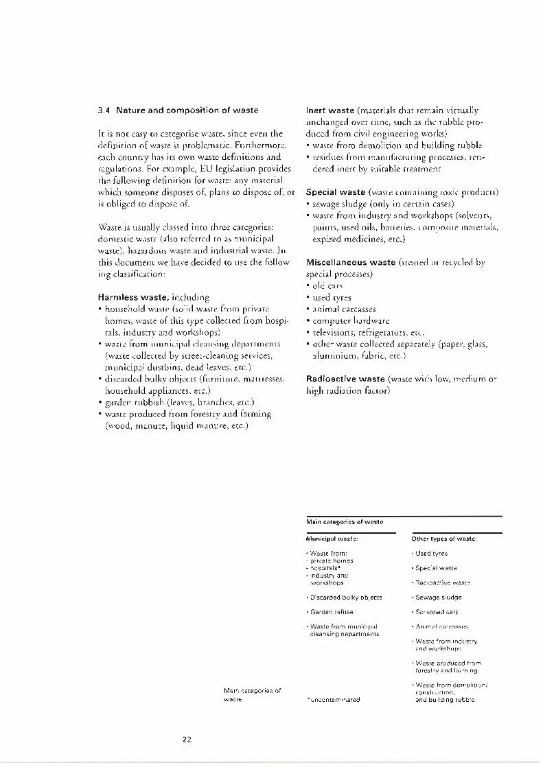
Main categories of waste
Radioactive waste (waste with low, medium or high radiation factor)
Miscellaneous waste (created or recycled by special processes) • old cars • used tyres • animal carcasses • computer hardware • televisions, refrigerators, etc. • ocher waste collected separately (paper, glass,
aluminium, fabric, ctc.)
Special waste (waste containing toxic products) • sewage sludge (only in certain cases) • waste from industry and workshops (solvents,
paints, used oils, batteries, composite materials, expired medicines, erc.)
Inert waste (materials chat remain virtually unchanged over time, such as the rubble pro duced from civil engineering works) • waste from demolition and building rubble • residues from manufacturing processes, ren
dered inert by suitable rrearrnenr
22
Main categories of waste
Harmless waste, including • household waste (solid waste from private
homes, waste of chis type collected from hospi tals, industry and workshops)
• waste from municipal cleansing departments (waste collected by streetcleaning services, municipal dustbins, dead leaves, ctc.)
• discarded bulky objects (furniture, mattresses, household appliances, erc.)
• garden rubbish (leaves, branches, etc.) • waste produced from forestry and farming
(wood, manure, liquid manure, etc.)
Waste is usually classed into duce categories: domestic waste (also referred co as municipal waste), hazardous waste and industrial waste. In chis document we have decided to use the follow ing classification:
le is not easy co categorise waste, since even the definition of waste is problematic. Furthermore, each country has its own waste definitions and regulations. For example, EU legislation provides the following definition for waste: any material which someone disposes of, plans co dispose of, or is obliged to dispose of.
3.4 Nature and composition of waste

Textiles. leather, rubber and wood 7%
Paper 2% Plastics 2% Metals 2% Glass 4% Other 22%
Vegetable matter 60%
Countries with low GDP
23
Vegetable matter 47%
Paper 14% Glass 2% Metals 2%
Textiles, leather, Other 10% rubber and wood 14%
Plastics 11%
Glass 10%
Textiles, leather, rubber and wood 5% Metals 8% Plastics 8%
12.5
0.1
Countries with average GDP
Other 13%
Vegetable \ matter 25%
Paper 31%
Major industrialised countries
Total
Miscellaneous 0.15
4.3
Carcasses
Sewage sludge
Special waste 0.3
1.0
2.0
0.0005
Waste from industry and workshops
Demolition waste (skips)
aluminium
0.5 0.14 0.05 0.015
0.35 0.025
fabric
Households and small businesses: paper glass organic matter
used aluminium
0.7
2.8
Reusable waste originating from: Industry and workshops:
scrap iron old cars and metal waste
Municipal waste
Municipal waste com- prises a complex mix- ture of objects and materials each with very different charac- teristics. These pie charts show the approximate distribu- tion, in weight, of the various materials con- tained in municipal waste, which depends mainly on a society's living standard (Source: Environmental Resources Limited).
The table opposite shows gives an idea of the quantities of waste produced in Switzer- land, broken down by category {estimate for 1987, in millions of tonnes). Source: OFPE

All the sludges are extracted in liquid form. Since this sludge is a byproduce of effluent treatment, there has to be an economical ,,vay of disposing of lt.
All these treatments produce sludge which rapidly scares to ferment unless created. A distinction is therefore made regarding "fresh sludge". Ferrnen ration is prevented by "stabilising" the sludge. There are three methods used to achieve this: anaerobic digestion, aerobic stabilisation and chemical stabilisation. The purpose of the first two methods is to remove some of the volatile substances, while the last process blocks fermenta tion by raising the pH.
The basic conventional effluent treatment pro cesses include: • simple primary clarification; • physical/ chemical clarification; • biological treatment using suitable bacteria.
Sewage treatment produces a sludge, whose qual ity and quantity varies according to the type of effluent treatment used, and of course rhe quality of the effluent being created. Different water treatment processes may result in varying levels of purification, which also have an influence on the quantity and quality of the sludge generated.
The sewage sludge problem Source and quality of sewage sludge: An EU directive governing rhe rreatrnenr of efflu ent specifies that over the next 1015 years efflu ent from urban zones will have to be processed in sewage treatment plants and, in ecologically sensi tive areas, any nitrogen aod phosphorus removed. Sewage treatment plants have been constructed in many countries, but the type of treatment provid ed and the percenrage of population served by these facilities still varies a lot from one country co the next.
24
In industrialised coun- tries, packaging is the biggest component of municipal waste.
(Source: ATOCHEM, Packaging Conference 1990)
250 kg 180 kg
4 kg
Annual packaging consumption per head of pop ulation: USA France Burundi
Each year in France alone people throw away 80 billion packages, empty bottles, cartons, plastic containers, etc. Currently in excess of 6 million tonnes a year, packaging accounts for a third of household waste in France and over 50% meas ured by volume, causing a real headache for the authorities who have ro dispose of it. The passing of regulations co make industrial producers responsible for their packaging and its eventual recovery should go some way cowards solving this problem.
The packaging problem Packaging has played a significant role in the development of waste. Statistics show that over the last thirty years, the mass of used packaging discarded by households trebled, while in global terms domestic waste increased by 60% (meas ured by weight) over the same period.

The use of sewage sludge in farming is sometimes questioned because of the pollu- tants it may contain. Special technology is required to incinerate sewage sludge.
Thermal drying can be used ro complement this process, resulting in sludges with a dry matter content of up to 90% or even greater.
The first stages arc the conventional ones: • chickening the separated or mixed sludges by
static or dynamic means; • dehydration by mechanical means, which can
take place after chickening, if fresh sludge is being treated, or afcer the sludge has been bio logically stabilised by undergoing an aerobic or anaerobic process.
This operation is performed seep by step, and it is always necessary co achieve the best possible yield from one stage before proceeding to the next one. Under these circumstances, investment and run ning coses can be reduced.
25
\Xlhatever the final destination of the sludge, there is always a need to reduce its volume in order to cur transport costs and also in the case of inciner ation to obtain, where possible, sludges that spon taneously combusc. Volume reduction is achieved by removing the interstitial water.
Incineration is now becoming the predominant method for disposing of sewage sludge, mainly because of the growing number of waste treat ment plants fined with the technology required co burn rhe sludge.
Sewage sludge is much more frequently used as a substitute for fertiliser in agriculture. The sludge has a high nutrient content (phosphorus and nitrogen) which can cause serious pollution of water courses and groundwater, a phenomenon known as eutrophication, ln addition, sludge drawn off from treatment plants generally con tains pollutants rhat have not been properly removed and which can have a harmful effect on the soil for many years. These pollutants mainly include heavy metals (zinc, copper, lead, cadmi um, mercury, erc.), pathogens and parasites. As a result, the use of sewage sludge in agriculture has become a major problem for the environment, and several countries are now starting co limit or even ban its use in farming.
Controlled dumping is becoming less common, and furthermore landfill sires are being built in increasingly remote locations.
There are a number of possibilities: • controlled dumping; • use in agriculture, either directly or after com
posnng; • incineration.


._ __ ...,__ --1. Final
residues
Dedusting of flue gases
27
District heating
,.._ _ __. Production of hot water
Electricity generation
Incineration
Dis- tTreated charge flue gases
Flue gas purification Heat recovery Delivery & storage of waste
The different residues produced by waste inciner ation and fluegas treatment are collected sepa rately and undergo suitable treatment before either being recycled or dumped.
To scare with, all the dust is removed from the combustion gases cooled in the boiler, and then the gases are purified in a very sophiscicaced flue gas rrearrnent system. Finally they arc expelled inco the atmosphere by an extractor fan chat sucks chem in and propels them up the stack.
This steam is normally used co generate electri city by means of a turbine. The electricity pro duced is used for the plant's own needs, and any surplus power is sold co the public grid. Alterna cively if rhe plant's location allows it, and if the infrastructure exists che steam can be used co produce hoc water for district heating or for industrial processes.
Trucks collect the municipal waste and dump their loads, afrer weighing, in the storage pit. The incineration furnace is constantly fed with waste by an overhead travelling crane equipped with a grapple. The combustion gases produced as the waste is incinerated on the grate of the furnace are forced around a boiler to produce steam.
4.1 How an MWT plant works
Scrubbing tower for the flue gases pro- duced by waste incin- eration. Sophisticated technologies have to be implemented to ensure environmental- ly sound waste treat· ment.
Schematic diagram of an MWT plant
4 Technical design aspects of a municipal waste treatment (MWT) plant

28
MWT plant in 1990
' t
The latest generation of waste treatment planes meets the most stringent environmental protec tion requirements. The plants reduce pollutants whether in solid, liquid or gas form (carbon monoxide, hydrochloric acid, sulphur dioxide, nitrogen oxides and hydrocarbons) co quantities that are well below the maximum levels considered to be hazardous to human beings and the environment.
As public authorities and the general public have become more environmentally aware, it has prompted major advances in plant design. Nowa days waste incineration is an integral pare of environmentally friendly waste management, and could even be considered to be the key element.
These planes consisted of nothing more than a furnace and a chimney stack, and were seen as truly heinous polluters by rhe local population.
Incineration plant in 1950
Like all technical installations, incineration planes have been continuously refined and improved over the years. However, from an envi ronmental viewpoint, it has to be said rhar the first significant advances were not made until the midseventies, with the installation of the first fluegas treatment systems. For over a century, engineers and designers concentrated all their efforts on improving the incineration furnace.
Incineration: an essential component of modern and environmentally sound waste management. The practice of waste incineration began over a century ago in Britain, as an attempt co find a solution ro the unbearable siruarion in big cities. Incineration was supposed co improve public health standards and prevent epidemics.
4.2 Thermal waste treatment
Until 1950, incineration plants only comprised a furnace and a chimney stack. Modern MWT plants have to perform far more complex tasks than simply reducing the volume and weight of waste through incin- eration.

By way of information, the calorific value of a tonne of household waste is equivalent co 200 kg of fuel, 250 kg of coal, 30 tonnes of hot water or 500 kWh of electricity. The heat recovered dur ing incineration can cover 46% of the energy needs of the population who produce the waste.
This aspect plays an important role when select ing the construction site for a new incineration plant. In general, if the findings of the environ mental impact study prevent the plant being sired near an enduser of steam or hoc water, che thermal energy is used solely to generate electric 1 ry,
Energy recovery can be applied in a number of ways: • co genera.re electricity; • co produce hot water co supply district heating
systems for homes, hospitals, public swimming pools, etc;
• ro supply steam for industrial processes; • a combination of all these uses.
Energy recovery Even if the incineration of household waste only conrribu res about 1 % of the total energy of industrialised nations, it would be inconceivable nowadays to burn waste without recovering the energy at the same rime.
29
300 kg
1000 kg of waste is reduced to 300 kg of solid residue
slag, fine dust, salts
0.1 m3
1 m3 of waste is reduced to 0.1 mJ of solid residue
Hygienic disposal All the organic matter, plus any pathogens, are destroyed by combustion at temperatures in the region of 900°C. Thus, incineration also prevents microbial contamination, since bacteria and viruses are destroyed at remperacures above 200°C.
Reducing the volume and weight of waste Since its inception, the purpose of waste inciner ation has been co reduce the quantity of end waste. Firstly, the volume is dramatically reduced: one cubic metre of household waste is converted into 0.1 cubic metre of solid residue after incinera tion. In terms of weight, 1000 kg of waste is con verted into 300 kg of solid residue. The reduc tion in volume also means char less land is need ed for public landfill sites.
In order to meet the latest environmental con trols, modern waste treatment plants muse per form the following funccio ns:
Reducing the volume and weight of waste by incineration

Water+ 5 - 15 kg of residues
Dust 20 - 40 kg !
Scrubbing - tower
30
Ash approx. 5 -15 kg
Slag approx. 250 - 350 kg !
-Purified flue gases
Incineration Heat Oedusting recovery filter
Materials flow separa- tion in an MWT plant Waste equipped with a wet 1000 kg scrubbing system for flue gases
Residual substances must first undergo various treatments before they can be dumped in land fills: After suitable treatment, the slag can be used as hard core for road construction.
Rendering residual substances inert Above all, separating the waste flow enables some materials co be recycled, such as scrap iron, slag, and depending on the Auegas treatment used gypsum, hydrochloric acid, or industrialquality sale.
Apart from che created Auegas, other matter pro duced by the plant includes: • incineration residues. The mass of slag consti
tutes, on average, 25% of the original mass of the waste, and just I 0% of its original volume.
• dust, known as fly ash, captured in the boiler and by the dusc filter.
• fluegas treatment residues (dried sludge, waste water, residues from the evaporation of waste water).
Incineration allows complex chemical com pounds, such as polymers or paints, to be partial ly broken down into basic constituents. By optimising combustion and the careful selection of fluegas treatment procedures, it is possible co minimise che pollutants emitted from the stack: the different residues can then be created separ ately using appropriate techniques.
It has been possible to integrate incineration into modern waste management systems by giving priority to the transformation and separation of materials.
Separation of materials flow Recent developments in waste both as regards quantity and quality plus tighter environmental controls mean we can no longer consider inciner ation as a simple method for disposing of waste by burning it, with the welcome byproduct of energy recovery.
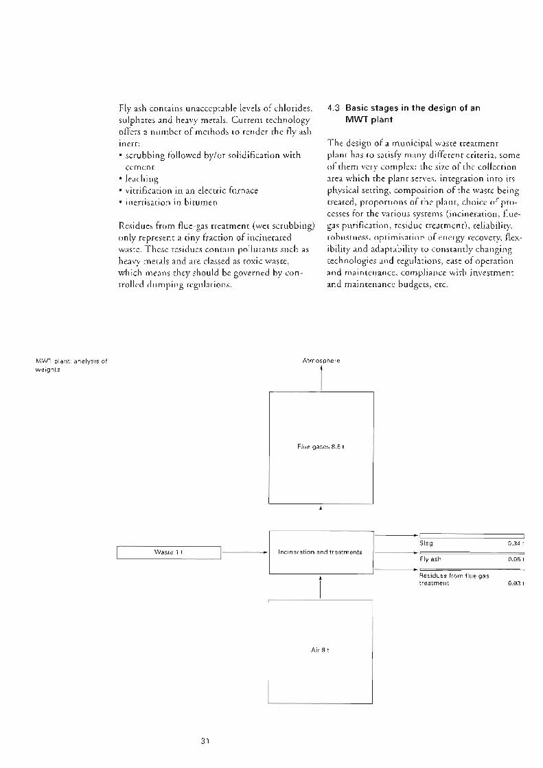
Air8t
0.03 t
f Residues from flue gas treatment
31
0.05 t Fly ash Incineration and treatments
0.34 t Slag
'-~~~W~a_s1_e_1_t~~~---'1•~~~~--,
Flue gases 8.6 t
Atmosphere
l
The design of a municipal waste treatment plant has to satisfy many different criteria, some of chem very complex: the size of the collection area which the plant serves, integration inco irs physical setting, composition of the waste being created, proportions of the plane, choice of pro cesses for the various systems (incineration, flue gas purification, residue treatment), reliability, robustness, optimisation of energy recovery, flex ibility and adaptability to constantly changing technologies and regulations, ease of operation and maintenance, compliance with investment and maintenance budgets, etc.
4.3 Basic stages in the design of an MWT plant
Residues from fluegas treatment (wet scrubbing) only represent a tiny fraction of incinerated waste. These residues contain pollu canes such as heavy metals and are classed as toxic waste, which means chey should be governed by con trolled dumping regulations.
Fly ash contains unacceptable levels of chlorides, sulphates and heavy metals. Current technology offers a number of methods co render che fly ash mere: • scrubbing foliowed by/or solidification with
cement • leaching • vitrification in an electric furnace • inerrisarion in bitumen
MWT plant: analysis of weights

Although there are already tens of modern iVfWT plants in service, there is no standard plant design. A pragmatic approach with the benefit of experience is the only way of finding a model chat offers the best compromise. To chis end, and as a useful link co the next paragraph, we quote the wording of a resolution passed on 7 May 1990 by the Council of the European Communities on waste management policy. This specifies that the main criterion in the selection of procedures is co make every effort co reduce pollucion to levels which, by current scientific standards, are considered to "make use of the most appropriate methods and technologies to guarantee a high level of protection for the environment and public health, taking into account best available technologies not entailing
. " excessive cost .
Even so, the decisionmaker's cask is made extremely difficult by the diversity of the proce dures available, local economic constraints, obli gations cowards the operator (who expects reason able constraints on the operation and mainte nance of rhe plant), the pressure exerted by the partisans of che new "miracle technology", and the moral obligation to support an investment with vision but one that is also sustainable.
The basic criteria for choosing the appropriate procedure seem straightforward: • combustion muse be correctly controlled to
avoid any transfer of pollution and associated nuisance (in Switzerland, for example, slag muse nor contain more than 3% unburnt sub stances);
• flue gases must be created so chat they comply with the maximum emission levels permitted by environmental regulations;
• the energy recovered from the waste incinera tion process must be sufficient to cover the plant's own energy requirements;
• the residues from the various systems muse be collected separately and then treated for subse quent recycling or dumping in a controlled landfill.
32
Choice of processes Nowadays there is a wide range of tried and test ed processes, ranging from incineration (grate furnace, shelf furnace, oscillating furnace, fluid ised bed furnace, ere.) to fluegas treatment (dry, semiwee, wee scrubbing, denirrificarion, etc.) and residue treatment (vitrification, solidification wich cement, washing with acid, etc.).
Environmental protection regulations stipulate rhar an environ men cal impact study must be completed before a new MWT plant is built. The documentation submitted when applying for a license co build and operate an MWT plane is always required to include an environmental impact study whose main aims are: • co inform che administrative authority issuing
the licence for the project; • to take into consideration the environmenral
data and concerns associated with the project; • to propose measures, where necessary, for the
elimination, reduction or making good any harmful effects on the environment.
The application for a licence initiates a proce dure, rhar emails in particular a public inquiry, co hear the opinions of all the different parties. Licensing procedures are usually very complex and vary immensely from one country to the next. A description of these procedures is outside the scope of this publication, and is not therefore included here.
Administrative constraints and obligations The construction and operation of M\'v'T plants are governed by licensing procedures particular co each country or region. These procedures impose legal and technical constraints on the var ious phases of planning, construction, operation and discontinuation of waste treatment activities.

However, waste is increasingly being collected separately and recycled thanks to better infra structures and the greater environ men cal aware ness of the general public. This should lead to a reduction in the quantities of waste being han dled. The gloomy economic ourlook and the introduction of waste collection taxes should also have an impact on the production of municipal waste. However, bearing in mind chat the average Hu of waste will increase between now and the year 2000, the incineration capacity of M WT planes will need to be about 1015% higher in ccrms of thermal power.
Despite major advances in waste analysis in recent years, it is impossible to make accurate forecasts as co the quantity and composition of waste in 510 years' time. Such forecasts are made even more difficult by the fact that certain factors have contradictory effects. The quantity of waste to be incinerated should normally increase, because the population is growing and the ban on dumping untreated waste will be extended. Furthermore, new decrees and legisla tion will come into force in a number of coun tries which will encourage waste incineration.
Any changes in the composition of the waste to
be incinerated in the plant will depend mainly on the waste management policy adopted by local authorities, which in rum requires chat environmental policy is coordinated at national level.
The thermal power of an M\VT plane is the product of the hourly throughput of incinerated waste multiplied by the calorific value of the waste, i.e. the energy contained in the waste. Given chat the lower heating value (Hu) depends entirely on the composition of the waste, forecasts of waste trends are absolutely essential when attempting to calculate the future capacity of rhe new MWT plant.
33
Dimensions of the MWT plant The capacity of an MWT plant is measured by the thermal power (i.e. energy) produced during the incineration process, which can then be har nessed and converted i nco steam or hoc water by means of a boiler.
Choice of location Ac the moment there arc two quire distinct approaches for choosing the site for a new M\'v'T plant. The first is to choose a location well away from town centres or residential areas, preferably near or on old waste dumps, in industrial zones or swamp regions. The second approach attempts to give maximum consideration to the environ mental impact study. In this case, a decision may be taken ro locate the MWT plant near the cen tre of town, co limit the nuisance caused by refuse collection trucks and other private vehi cles. The environmental and architectural aspects play an essential role here because, apart from ensuring char che plant blends in aesthetically with its setting, controls on emissions, noise, odour and pollution are obviously very impor tant. Although this second approach usually emails a more substantial investment, ic also offers significant benefits which arc fully exploit ed in the choice of the sire (reduction of trans port costs and nuisance, better integration into the environment, proximity to endusers of heat, erc.).
Choice of investment Tn some countries the financial aspect is only of relative importance because each new plant con structed must be capable of achieving "zero pol lution" and the investment required to build a new averagesized (150,000 ronnes p.a.) MWT plant can easily exceed ECU 500 million. In ocher countries, on the other hand, the idea of "taking into account best available technologies not entailing excessive cosr" is scill a decisive fac tor when choosing procedures and technologies. Tn this case, the i nvcscmcnt is unlikely co exceed ECU I 00 million. Chapter 6 provides more detailed information on cost aspects.

If there is a serious fault char rakes longer co repair, there are generally agreements for the transfer of waste between regions, which also ensures that excess capacity is more evenly dis tributed and ultimately provides a better return on the capital invested in the construction pro ject.
As a general rule, the MWT plane is kept run ning seven days a week to prevent corrosion or premature ageing problems in the installations. To ensure that the plant maintains operation, even at a reduced capacity, for the whole year, MWT plants usually include several processing lines. The service life of an MWT plant is around 20 years.
Because of shutdowns whether scheduled or unscheduled as a resuJ r of general overhauls or repairs, it is impossible for an installation to operate 24 hours a day throughout the year. The availability faccor generally aimed for when a project is drawn up is in the region of 85%. This value is theoretical and assumes that a processing line cannot operate more than 7,500 hours a year (8760 hours x 0.85).
Loading Although the dimensioning of every new MWT plane must cake into account numerous parame ters including chose described above, oversizing rhe treatment capacity will lead to an unsarisfac rory business result: annual debt servicing (inter est and valuation readjusrmenrs) would be spread over too low a volume of created waste. Bearing in mind the very high cost of modern MWT planes, coo much reserve capacity could have a negative impact on che operating quality.
34
Previous comments about the production of household waste also apply to the Hu, i.e. the bigger a cicy, the higher the Hu of the waste it produces. Another point worth noting is that the Hu of waste produced in Northern cities is high er than in the South. The main reason for chis is char Northerners rend co consume more pack aged foods and goods, whilst Southerners con sume fresh produce bought in markers or grown in their own gardens.
\X'ith the huge increase in plastic as a component of consumer goods (especially packaging), the average Hu of waste has risen sharply over che last 15 years or so. Sorting waste at source, recy cling by composting organic matter and intro ducing separate collection of glass and metals have led to an increase in the average Hu of the waste to be incinerated. As we already said, rhe calorific value of synthetic materials is very high, whereas for organic waste it is very low, and vir cual ly nil for glass.
Impact of changes in calorific values on incineration capacities The average Hu of waste is a key factor for calcu lating the size of an M\X1T plant. At the time when most MWT plants were constructed, the average Hu of waste was between 6,000 and 10,500 MJ/t. ln Switzerland it is estimated char the current average Hu of 11,500 MJ/r will climb co 12,600 MJ/r by che year 2000.

35
Fluidised bed furnace Rotary kiln
Rotary kiln Grate furnace Fluidised bed furnace
j
Dried sewage sludge, used oils and production waste (plastics, wood, etc.)
Industrial and special waste (solids, liquids and pasty). contaminated soil
Municipal and similar waste
The table below provides an overview of the main types of furnace used, depending on the nature of the waste to be incinerated. There arc of course other processes, such as chose involving oscillating furnaces, shelf furnaces, pyrolysis, plasma furnaces etc. These technologies go beyond the scope of this report and so we shall limit ourselves co the mosr commonly used methods. Nevertheless, pyrolysis treatment offers interesting prospects and is therefore described briefly at rhe end of the chapter.
There is no single solution to the problem of incinerating the mountains of waste which we produce every day. ln fact, a wide range of options is available for thermal treat men c of waste under environmenrally sound conditions.
The thermal treatment of waste by incineration involves burning the waste in special furnaces suited to the composition, granulometry, calorif ic value and moisture conrenr of the waste. Com bustion must be correctly controlled to avoid any damage to the installations and to ensure com plete combustion of the organic matter.
4.4 Main processes available for waste incineration
bustion diagram. The shape of the diagram can vary depending on the Hu range of the waste being incinerated, the type of furnace and the plant's constructor.
The straight lines represent the Hu of the waste co be treated. Point A is the plant's nominal operation. Performance testing is usually carried out at this point (combustion quality, calorific output, treatment of flue gases, consumption, etc.). Tests can also be performed at a minimum operation level to rnonicor the quality of com bustion when waste with a low Hu is incinerated at low temperatures. Obviously the installations must be capable of operating in compliance with technical specifications, within the entire com
Waste throughput [tonnes per houri
PCI = 8370 kJ/kg
Main combustion systems for different types of waste
Combustion diagram of a grate furnace.
ol
2
4
6
8
10
12
14
16 ,,,__ 12000 kJ/kg
Combustion diagram The combustion diagram represents the opera tional zone of the furnace. The values on the Y axis show the gross calorific value of the furnace in megawatts, while the X axis shows the capacity in terms of mass (tonnes per hour) of incinerated waste.
Gross thermal power [MW]

36
Slag Primary air
Counter-current reciprocating grate The waste is conveyed by gravity down the slope of the grace. Ir is stirred by the bars which move in the opposite direction co the waste flow.
Combustion gas
t Waste
'CJ Counter-current reciprocating grate
Primary air Co-current reciprocating grate The waste is conveyed and stirred by the alternat ing movement of the grate bars. With the cocur rent reciprocating grate, the grace docs not have to slope in the direction of the waste flow.
l Slag t
Roller grate The combustion bed is situated on a number of rollers arranged one on top of the ocher in suc cession to form a grate. The waste is conveyed and stirred by a combination of gravity and the rotary movement of the rollers.
Waste
'CJ Co-current reciprocating grate
Grace systems arc divided into two groups depending on the conveyor method used: • continuous conveyor grares (e.g. roller graces) • disconcinuous conveyor graces (cocurrent
reciprocating grace, countercurrent reciprocat ing grace)
Combustion gas
t
Slag Primary air
t The most widespread thermal treatment of waste involves incineracion on a grate, and chis technique has also had the most proven success. For many years, grate incineration has been common for the thermal treatment of municipal and similar waste in solid form. This method is not suitable for incinerating liquid waste or sludge because coo much of the waste would fall through the gaps in the grace without bci ng incinerated.
Combustion gas
4.4.1 Combustion grate furnace
'CJ Waste
Roller grate Principal types of combustion grates

37
7
8
10 I Waste
I
Illustration of a recip- rocating grate furnace
4 Combustion grate 5 Recovery boiler 6 Residue removal 7 Removal of grate
sifting 8 Removal of fly ash 9 Primary air system 10 Secondary air
system
ber
1 Charging hopper 2 Feeding device 3 Combustion charn-
furnace/boiler Cross-section of the Grate furnace.

Because of the lower tempera cures, relatively less nitrogen oxides (NOx) are formed. The coses of creating che flue gases can be reduced by injecting dolomite or calcium carbonate directly inco the fluidised bed, to partially neutralise the acid pol lucancs such as SOx and HCl.
Thanks co the high thermal inertia of the fluid ised sand bed (800°C) it is possible co incinerate waste with a highly variable and very low heating value without any significant change in operating parameters. The properties of this bed, which are similar to chose of a fluid, guarantee good efficiency in terms of thermal transmission and a good exchange of matter, resulting in more thorough combustion and enhanced thermal efficiency of the installation.
Compared with conventional incineration of waste on graces, chis technology has che following advantages:
Fluidisedbed incineration is an alternative pro cess to conventional incineration. le involves combustion of matter in a vertical furnace with a layer of sand in its base. This sand is brought inco a state of fluidisation by the combustion air injected inro the base of the furnace via a large number of nozzles.
4.4.2 Fluidised-bed furnace
38
Acrual combustion cakes place in the second and third zones of the grate by means of the combus tion air injected across the grace. In the lase zone, combustion is com pieced and the surplus air guarantees coral combustion of the slag. Once the waste has been completely burnt up, the residual slag and ash fall ch rough a shaft into the ram discharger.
The waste is pushed by the ram feeder as far as the first zone of che grate the drying zone where it is spread out and dried by the passage of combustion air and by the incense heat from the flames and the refractory walls of the furnace.
Different phases of incineration on a grate A carefully controlled admission of air under the grace (primary air) enables the three phases of combustion co take place, one after the other: drying, degassing and gasification. The gases are fully combusted thanks ro a supply of secondary air in co the hearth above the grace.
Remarks: Since the first waste incineration plant was con structed in Britain in 1876, many companies have developed and built numerous varieties of grates, some of which no longer exist. Ac the present time in Europe, the most popular grates are the roller grate (Babcock), the countercurrent reciprocating grace (Martin) and rhe cocurrent reciprocating grace (Von Roll). Ocher firms have produced many variants of these basic grate designs.

Fluidisedbed incineration is used mainly for combustion ofwaste with a low heating value or which can be easily shredded: • production waste such as plastic residues, wood
chips etc. • industrial sludge and sewage sludge • combustible materials obtained from process
waste, screened materials, tyres • used oils, solvents.
Compared to a convencional furnace wich a combustion grate, waste incineration in a fluid isedbed furnace has two major drawbacks: • because of the technical difficulties of removing
sizeable residues from the fluidised bed (pieces of scone, metal etc.) the waste muse be sorted and shredded before being fed into the furnace;
• co avoid the risk of melting the sand bed, the temperature in the combustion chamber is maintained at approximately 800°C. This means that fluidisedbed furnaces can not be used to incinerate industrial waste in countries where the minimum combustion temperature 111 use not fall below 1200°c.
There are also intermediate examples such as the "rurbofluidised bed" which combines the advan tages of slow and rapid fluidised beds.
Depending on the degree of fluidisarion of the sand bed, a distinction is made between: • stationary (dense) Auidisedbed incineration; • circulating fluidisedbed incineration; • rapid fluidised bed, highexpansion fluidised
bed.
39
t Flue gases pass to the boiler
5 Furnace feed 6 Injection nozzles 7 Start-up burner
work
1 Fluidisation nozzles 2 Fluidised sand bed 3 Combustion cham-
ber 4 Refractory brick-
Stationary fluidised- bed furnace
The floor of a station- ary fluidised-bed fur- nace showing the noz- zles for injecting the combustion {and fluid- isation) air

40
front wall The primary combustion air is admitted via a ring system, at the same time cutting off the air so as to seal off the rotary kiln. The front wall contains a removable chute with its own water coolant circuit.
waste feed devices for waste in solid, pasty and liquid form and in barrels.
Rotary kilns arc essentially used for incinerating hazardous waste in liquid, pasty or solid form, and for thermal treatment of contaminated soils. They are nor used for incinerating municipal waste, but since every one of us produces special waste (batteries, used oils, expired medicines, paints erc.) we believe it is worthwhile summaris ing the methods of eliminating these dangerous wastes.
The rotary kiln comprises the following ele ments:
4.4.3 Rotary kiln
Rotary kiln in an incin- eration plant for haz- ardous waste

ri . . '
_)
41
8
011
70
10
The main characteristics of rotary furnace incin eration are: • good flexibility to deal with different types of
waste; • high combustion temperature; • slag removal in the dry or molten state; • prolonged residence time (4 seconds) of com
bustion gases at high temperature (l 200°C).
Drying, degassing, gasification and combustion essentially take place in rhe rotary kiln. The gases are burnt up in the secondary combustion cham ber which is equipped with booster burners to maintain the correct combustion temperature at all times.
secondary combustion chamber This section of rhe furnace is lined with refracro ry bricks and is specially designed co ensure com plete combustion of the gases. Tc narrows ar the point where the secondary combustion air is admitted at high speed to ensure chat the gases are thoroughly mixed.
rotary kiln The rocary kiln comprises a steel cylinder which is slightly inclined (by approximately 3") with an internal lining of refractory bricks and an exter nal drive system. The materials to be incinerated are transported from one end of rhe furnace to
the ocher by a combination of the sligh r slope and the rotary movement.
12 Slag removal tion
7 Secondary air system
8 Combustion cham- ber
9 Kiln drive system 10 Secondary com-
bustion chamber 11 Waste water injec-
waste
1 Feeding by means of overhead travel- ling crane
2 Barrel feeding system
3 Primary air system 4 Booster burner 5 Injection of liquid
waste 6 Injection of pasty
Rotary furnace with waste feed system and post-combustion chamber

The admission of oxygen into the reactor leads to rhe formation of a synthesis gas composed of car bon monoxide, hydrogen, water vapour and car bon dioxide. This gas is rapidly cooled to 90°C by rhe injection of water upon emergence from the reactor to prevent the formation of dangerous substances such as dioxins and furans. The next
The very dense mass of waste is continuously pushed inro the heated degassing channel in which ir is dried at 600°C and organic matter is carbonised. At the end of the chan ncl, the degassed waste falls into a hightemperature reac tor where organic substances are broken down into their basic components at a temperature of 2000°C. Reaction residues accumulate in the bottom of the reactor in the form of a vitrified produce and scrap metal. Metal must be removed from this residue before it can be recycled e.g. as hardcore material.
Thermoselect pyrolysis installation for treatment of municipal waste The most innovative aspect of chis process is chat a carcrusher is used to compress unsorted waste to a tenth of its original volume before it is intro d uced into the degassing channel. The major advantage of chis operation is chat a large part of the oxygen contained in the waste is extracted (remember rhar degassing muse be carried out in an oxygendeficient atmosphere).
their attention to pyrolysis. To avoid being lefr behind, some designers of conventional M\'v'T plants have developed a combined pyrolysis/com bustion method for treating mixed heterogeneous waste. The installations have the attraction of combining proven conventional technologies for degassing waste. The pyrolysis gases are burnt in a postcombustion chamber. Slag is vitrified at a high rcmperaturc I» t 200°C) to produce an inert product which can be recycled without further treatment.
42
However, despite adverse experience in the past and the uncertainties surrounding pyrolysis, the process has by no means been abandoned. The advantages are such that many firms have turned
Pyrolysis is less suitable for the treatment of waste materials as heterogeneous as municipal refuse. Pretreatment (e.g. sorting, shredding or compacting) is necessary co meet che minimum operating requirements.
A great deal of research has been carried out over the past 30 years into rhe use of pyrolysis tech nology for: treating waste. Pyrolysis involves sub mitting a produce (waste materials, coal etc.) in an oxygendeficient atmosphere co temperatures in the region of 500°C in order to convert it into gas, hydrocarbons and carbonised residues. The gas produced in chis way is not burnt (lack of flames) and thus has a certain Hu. The original idea was to recover useful materials such as fuel, coke etc. in so far as possible and co utilise che energy released by the pyrolysis gases. Many pro cesses based on this concept have been effected and tested in pilot installations. However, pyroly sis has yet co establish itself. Only a few special installations designed for very specific types of waste (plastics, tyres, electronic components) arc currently in service.
The incineration of municipal waste in tradition al grate furnaces is based on proven technology, but there is limited scope for further perfor mance improvements. The new requirements which waste treatment planes now have to satisfy have prompted designers co steer their research towards new methods. Despite the excellent envi ronmental performance of modern MWT planes, chey have been criticised for producing excessive quantities of toxic residues and for being too expensive.
4.4.4 Pyrolysis furnace

Toxic residues
t ~
T Salts
9
rl ------•~Purified water
~
r----: Purified {IVr\ synthesis ~ gas
7
6
Despite these considerable advantages, one should not overlook the drawbacks of the pro cess, which arc essentially as follows: • safety problems due to high temperatures, the
risk of explosive gas compounds and matter subject to high stresses;
• low overall thermal efficiency; • uncertai ntics regarding the efficiency and avail
ability actually attainable with an industrial scale plane;
• difficulties in estimating operating and mainte nance costs (rapid wear of refractory, burner nozzles, ctc.).
43
Inert residues
Compared with incineration in a conventional furnace, rhis process has the following advantages: • a small volume of Auegas is produced, contain
ing significantly less pollutants; • there is minimal production of toxic residues
requiring controlled disposal or special treat ment;
• the system is more compact and in principle less expensive.
phase involves treatment in scrubbing towers, where compounds of sulphur and other pollu tants are captured or neutralised. The energy contained in the synthesis gas is used to generate electricity and to heat chc degassing channel.
5
l
~ I t + •
8
-
1 Crusher 2 Degassing channel 3 Reactor 4 Quench 5 Gas scrubbing
towers 6 Cooler/dryer 7 Activated carbon
filter 8 Treatment of gas
scrubbing water 9 Evaporation
Thermoselect pyroly- sis installation

Tc is, of course, impossible co show in a single cable all the emission limits permitted in individ ual countries. The cable opposite gives an idea of che performance levels which must nowadays be met by fluegas treatment systems in European waste treatment plants. Clearly these values are not definitive and they tend co evolve with changing environmental regulations and techno logical developments.
4.5.3 Emission controls
In view of the heterogeneous nature of municipal waste, che composition of the combustion gases and thus the concentration of pollutants in these gases vary widely. Treatment of the flue gases pro duced by M\TI plants is therefore significantly more complex than in, for example, coal or gas fired thermal power stations.
4.5.2 Pollutant concentrations in untreated flue gases
The table opposite summarises the pollutants present in combustion gases from municipal waste incineration and some of the base materials from which they originate.
4.5.1 Formation of pollutants in combustion gases
44
1 Emission: emission of pollutants 2 Transmission: dilution, transport and transformation of
pollutants 3 lmmission: concentration of pollutants damaging to
humans and the environment (dusts and rain)
000 [[][[][[]
Three aspects of air purity
Incineration has long been regarded as one of the main causes of air pollution. This explains the hostile response and adverse public opinion every time a new MWT plant is constructed.
The air quality controls chat have to he complied with are nothing new, nor are they a passing fash ion: they represent a basic requirement for man and the environment.
The nature and quantity of the pollutants con tained in the flue gases depend on the composi tion of the waste, the combustion system and the incineration conditions.
The main problem of waste incineration is the production of flue gases laden with dusts and all manner of pollutants, especially acids, nitrogen oxides and heavy metals, which must be elimi nated by means of fluegas treatment systems.
4.5 Flue-gas treatment

45
Pollutant concentrations in untreated flue gases
Substance Range Unit H,O 10 18 Vol.-% co, 6 12 Vol.-% 02 7 14 Vol.-% co 20 600 mg/Nm3
HCI 400 1 500 mg/Nm3
HF 2 20 mg/Nm' so, 200 800 mg/Nm' NOx 150 400 mg/Nm' Dioxins I furans (TE) 1 15 ng/Nm3
Dusts 800 15 000 mg/Nm3
________ w_o_o_d chips, secondary reactions dioxins Organochlorines
Pb (lead) b_a_tt_e_ries, paints, __ cu_r_t_a_i n_s _ Zn (zinc) batteries, paints, galvanised products Cd (cadmium) batteries, synthetic fabrics, inks Hg (mercury) batteries, thermometers, amalgams ________ .:,c_ ''
Heavy metals
PVC, cooking s_a_lt _ paper, dyes, sludge, rubber insulators, Teflon, sprays, refrigeran_t_s _ textiles, nylon, proteins, secondary reactio __ ns _ electronic components, non-flammable fabrics
HCI (hydrochloric acid) S02 (sulphur dioxide) HF (hydrogen fluoride)
------------ NO 2 (nitrogen oxides) HBr (hydrogen bromide)
Gases
all wastes soot, ash, salt Dusts
Origin Substance Category
Pollutant concentra- tions in untreated flue gases
Pollutants present in combustion gases from waste incinera- tion
Authorised emission Emission limits limits at the stack out- let of MWT plants
LRV91 17.Blm.Schv RV89 EU MWT plant EU MWI plant CH D NL EU EU
Dusts 10 10 5 30 5 HCI 20 10 10 50 5 HF 2 1 1 2 SO, 50 50 40 300 25 NOx 80 200 70 Hg 0.1 0.05 0.05 0.2 (Hg+Cd) 0.05 Cd 0.1 0.05 0.05 0.1 0.05 Sum of heavy metals 1 0.5 1/5 0.05 co 50 50 50 100 5 C tot 20 10 10 20 50 Dioxins TE (ng) 0.1 0.1 0.1

5
Capturing the heavy metals present in the flue gases in their gaseous and aerosol form remains a problem, however, since these elements cannot be neutralised by the lime nor intercepted by the filters. Installing a heat exchanger at the intake of the fluegas treatment system in order to condense certain gaseous heavy metals normally carries risks of corrosion and fouling without guarantee ing satisfactory results.
One of the drawbacks of this process is the high quantity of reagent needed for the reaction (the stoichiometric ratio is greater than two): more than half of it ends up in the residue without having contributed ro the fluegas neutralisation process. Furthermore, dcdusting must be carried out using a bag filter as this greatly improves the relatively modest efficiency of the dry scrubbing process (the dusts and reagencs adhere to the fil tration fabric and increase the duration of con tact with the flue gases to be treated).
Dedusting of flue gases always rakes place after the neutralisation stage. Tn chis way it is possible co simultaneously capcure the dust and ash from combustion, the reaction produces and rhe un re acted lime particles.
46
l 6 vlucucuL, ,zzzzzzzzzzzr
/\ IZ/27222221 ~
2 3
Purified flue gases
The pollutants (HCl, 502 and HF) absorbed on the surface are converted into other substances (calcium salts), buc the interior of the particles is not altered by this transfer. This means char the larger the particle, the greacer the loss of absor bent.
Dry scrubbing In this process, a dry neutralisation agent in the form of lime (Ca(OHh) or limestone is sprayed in a counterflow system in a reactor. Contami nants are transferred from the gas co the surface of solid particles.
Fluegas treatment involves physical separation of solid matter (dusts, fly ash, salts) and chemical separation of gaseous pollutants (HCI, S02, HF, NOx and certain heavy metals). There are essen cially three different technologies currently used for this purpose. These are as follows:
4.5.4 Principal methods of flue-gas treatment
1
1 Flue gases coming from the boiler
2 Reactor 3 Filter 4 Fan 5 Stack 6 Dust removal 7 Residue bin 8 Recycled lime 9 New lime 10 Compressed air 11 lime silo 12 Injection of lime
Schematic diagram of flue-gas treatment by dry scrubbing

5
Because of the serious technical drawbacks and, above all, the low efficiency of dry and semidry scrubbing, fluegas treatment systems based on these methods are hardly in operation in coun tries with stringent environmental controls, such as Switzerland or Germany.
As with dry scrubbing, the removal of large quantities of filtered residues poses serious prob lems since these are classed as toxic wastes in most countries. Therefore they muse either be taken to a controlled dumping facility for dan gerous wastes or undergo specialised and costly trearrnent.
All these solid particles are captured in a dedust ing filter positioned downstream of the reactor. The filters used in this fluegas treatment system are bag filters. Compared with electrostatic fil ters, these filters have the advantage of improving the overall efficiency of the treatment system, since the flue gases are brought into contact with the still accive neutralisation produce which is deposited on the filter fabric.
47
.___v __ ·0__~_M 3 2
Purified tlue gases
le involves spraying the lime in dissolved form (lime milk) in an atomiser. The particles which, in the first instance, help cool the flue gases are reduced co che saturarion limit of the absorbing agent by evaporation of rhe excess water. It is then chat actual transformation of matter from the gas phase to the fluid scare takes place. The residual water continues to evaporate until only a totally dry, pollutantladen particle remains. The heavy metals are condensed on particles of dust and neutralisation produces which are present in the flue gases.
Semi-dry scrubbing This process is a variant of dry scrubbing. Tc neu tralises the acid pollutants contained in the flue gases and cools rhe flue gases by injection of water co help the heavy metals condense.
,_n__; _ _.,
1 Flue gases coming from the boiler
2 Reactor 3 Filter 4 Fan 5 Stack 6 Dust removal 7 Residue bins 8 Recycled lime silo 9 New lime silo 10 Lime milk prepara-
tion vessel 11 Injection of lime
Flue-gas treatment by semi-dry scrubbing

According to current water pollution regulations, these effluents may not be discharged into the natural environment. Tn view of their very high acidity and heavy metal content, they also are prohibited from discharging into a sewerage system leading co a municipal sewage plane. As a result, part of the scrubbing effluent is drawn off and then led to the internal effluent cleansing plant, where the acids arc neutralised by the addition of lime milk and form gypsum (CaS04), sodium chloride (NaCl) and some CaC'2. The heavy metals contained in the effluent are flocculated and precipitated to form insoluble sludges in the water. These sludges are finally separated in a filter press and the pH of the water is adjusted before it is discharged into the drainage system or rivers.
\Vasce water from rhe fluegas treatment installa cion contains hydrochloric acid, sodium sulphate (where sulphur oxides are neutralised with caus tic soda), heavy metals and fine dusts.
Fluegas treatment systems based on wet scrub bing include: • an initial conditioning stage called a "quench"
in which the flue gases are saturated by injec tion of a large quantity of water;
• a multistage scrubbing cower in which pollu tants are extracted from the flue gases in gaseous form. Heavy metals in the form of aerosols are condensed and then carried away with the scrubbing water.
48
Filtered residues from flue-gas treatment by semi-dry scrubbing present a real disposal problem.
To avoid fouling problems in the scrubbing installations, the flue gases must be dedusred on leaving the boiler kiln. Electrostatic precipirators are normally used for this. Bag filters arc less commonly used, being more sensitive to fluegas temperatures which are still high at the output of the boiler. Furthermore, in this process the filter does not have to perform any neutralisation function.
Wet scrubbing This process involves removing pollutants from the flue gases by intensive scrubbing with water. These systems deliver the best results in terms of fluegas treatment, as they are effective even without chemical reagents.

12 l t t D 0,3 I I L; Purified
water
10
11
+
0 8
6
Purified flue gases
In view of increasingly stringent air pollution controls, fluegas treatment systems using wee scrubbing are becoming imperative in many countries.
\Vee scrubbing of rhe combustion gases has major advantages over ocher processes: • maximum capture of pollutants (HCI, HF,
502, heavy metals) • selective capture of individual pollutants is pos
sible • extremely low residual emissions • almost stoichiometric consumption of chemical
products • minute g uanriries of residue.
9
7
49
J J
2
Where effluent discharge is either undesirable or prohibited, it is possible to bypass the effluent cleaning plant. This is referred to as "effluentfree wee scrubbing". The flue gas scrubbing water is directed to che cop of the gas treatment system where ic is evaporated in a dryer/atomiser situa ted between the boiler and the dedusting filter. The considerable heat of the flue gases is used to
crystallise the salts contained in the scrubbing water. These sales are partially recovered at rhe base of the dryer and the remainder is intercept ed during the dedusting of the flue gases carried out prior to scrubbing.
9 Water from the first stage
10 Drawing off used water
11 Neutralisation 12 Settling tank 13 Sand filters 14 Sludge thickener 15 Sludge press 16 Toxic residues
Flue gases coming from the boiler
2 Dust filter 3 Quench 4 Scrubbing tower 5 Fan 6 Stack 7 Water 8 Caustic soda
Wet scrubbing of flue gases with treatment of scrubbing water

Purified flue gases
5»
Selective Catalytic Reduction (SCR) method Reduction of the nitrogen oxides NO and N02 in the combustion gas, called selective catalytic reduction, takes place when a solution of ammo nia is added to the gas as a reducing agent and when this mixture is fed into a catalyser where the nitrogen oxides and the ammonia are con verted into nitrogen and water vapour.
(NH3) into the first passage of the boiler. At tem peratures in the region of 900°C, the nitrogen oxides (NOx) are reduced co give N2 and H20. The excess ammonia carried by the flue gases is recovered in separation columns. The major diffi culty with this process is the scrong odour of ammonia that pervades the area surrounding the i nsrallations.
50
•
Selective Non-Catalytic Reduction (SNCR) method Selective noncatalytic reduction is a method for the thermal reduction of NO (nitrogen oxide) by NH3 (ammonia). To reduce the nitrogen oxide content of rhe combustion gases, ammonia is injected in the form of an ammonia solution
At present the t\.YO most common processes are:
Certain countries have imposed limits on nitro gen oxide emissions. This means that MWT plants must be equipped with systems for denit rifying the combustion gases (i.e. NOx reduction systems). Using such measures, it is possible to reduce the concentration of nitrogen oxides in the flue gases at the output of the stack to 80 mg ofNOx/Nm3.
4.5.5 NOx reduction (denitrification)
1 Injection of ammo- nia solution
2 Kiln combustion chamber
3 Dedusting filter 4 Flue-gas scrubbing
tower 5 Extractor fan 6 Treatment of flue-
gas scrubbing water
7 Stripper 8 Condenser 9 Ammonia reservoir
Schematic diagram of denitrification by the SNCR method

8
Bag filters are generally used co reduce the con centrations of these pollutants in the flue gases. Dioxins and furans are adsorbed in the bag filter by injecting activated carbon into the fluegas channel upstream of the filter. The particles of acrivared carbon form a filtering layer on the fil ter fabric, and che adsorbent properties of the carbon cause part of the dioxins and furans, in the gaseous state, co be captured and then removed along with the dust.
At the present time, only a few countries lay down emission limits for dioxins and furans (in Germany, their concentration is limited co 1 ng/Nm3). The concentration of dioxins in waste combustion gases is so tiny chat construc tors have great difficulty measuring chem: they have to filter thousands of cubic metres of flue gases co capwre a measurable quantity of dioxins. The concentration of dioxins and furans in flue gases is a few tens of a nanogram.
Studies have shown that minute craces of com plex components called organochlorincs arc formed during che incineration process. These arc made up of combinations of hydrogen, chlo rine and oxygen. Hundreds of different combina tions exist, but the best known arc dioxins (PCDD) and furans (PCDF) (see p.92). These produces do nor exist in nature and in principle are not manufactured commercially. They occur in M\'(!T planes after combustion. They are formed mainly by recombination from unburnt residues of fly ash, in a temperature range between 250 and 400°C.
4.5.6 Dioxins and furans
51
For reasons of economy, the flue gases leaving the scrubber at approximately 60°C are reheated in two srages. In rhe first stage, they are reheated to between 290 and 320°C in a heat regenerator where they flow in the opposite direction co very hot denitrified gases. In the second stage, a burn er or a heat exchanger raises the temperature by a further 30°C .
The caralyser is normally a complete catalytic assembly of honeycomb design made from acti vated titanium dioxide as the basic ceramic mate rial, with catalytically activated inserts chat vary depending on rhe manufacturer. The optimum operating cernperacure for the cacalyser is between 320°C and 350°C.
1 Arrival of flue gases from the flue-gas scrubber
2 Preheater 3 Booster burner 4 Ammonia injection 5 Ammonia reservoir 6 Catalyser 7 Extractor fan 8 Stack
Schematic diagram of denitrification by the SCR method

1 Arrival of flue gases from scrubbing system 2 Injection of activated carbon 3 Bag filter 4 Dust silo 5 Activated carbon silo
The biggest changes in the field of fluegas treat ment may well come from new methods of ther mal treatment of waste such as pyrolysis or plasma furnaces.
The next stage, which has already been reached in some countries, is co develop fluegas treat ment systems which limit the quantity of resi dues requiring disposal to just a few grams per ton of incinerated waste. In such systems, hydro chloric acid or gypsum is produced from the HCI and S02. Heavy metals such as zinc and mercury can be recovered, or industrial quality salt can be produced in an installation for evaporating the fluegas scrubbing effluent. However, the addi tional investment needed to attain these perfor mance levels is so large as co make these recycled produces far too expensive to be marketed com mercially.
Scaceoftheart technologies make it possible to intercept all pollutants present in flue gases pro duced by the combustion of municipal waste and to reduce their concentrations co minimal or almost undetectable levels. As a result, certain operators have claimed that their MWT plants actually purify the air in their towns and cities.
4.5.7 Outlook
52
To the ~-[~-1___,o combustion chamber
Bag filters
~UJ I 1-~-
Purified -flue
gases
Adsorbent bag filter
The bag filter is installed at the end of the con ventional fluegas treatment systems. Ics purpose is to reduce all residual emissions (mercury, diox ins, heavy metals, dust) to the limit of detectabil ity. A fixedbed activated carbon adsorber can be used as an alternative to a bag filter.

Residues approx. 40 - 70 kg
l ! Dust Solid residues approx. 30 kg approx. 5 -15 kg
Purified Dry reactor Oedusting flue gases
filter
! Residues approx. 50 - 90 kg
Semi-dry Oedusting reactor filter
Wet scrubbing
Dedusting filter
On the MWT sire, these residues must be stored separately and deposited in impervious contain ers protected from rain and wind, ensuring that any runoff water is collected.
All these residues, resulting from different stages of waste treatment, must be treated so that they can be reutilised or finally disposed of without posing any longterm danger co the environment.
In wee scrubbing systems, the pollutants are trapped in the scrubbing water which is purified in the scrubbing tower to produce a solid residue containing a high concentration of toxic sub stances.
Fluegas treatment plants using dry or semidry scrubbing produce residues containing ash, soluble salts, chemical reagents and heavy metals.
53
Ash approx. 5 -15 kg
Slag approx. 250 350 kg l !
Waste 1000 kg Incineration Heat
recovery
The residues produced ac the various srages of treatment are as follows: • slag, which is the combustion residue recovered
at the output of the furnace; • dusr and fly ash carried along by the combus
tion gases and incercepced by the dedusring system and, to some extent, under the boiler;
• the fluegas treatment residues which vary according to the processes used.
Modern waste treatment complexes are able to separace che flow of materials. This has the advantage chat each material flow can be treated in an appropriate manner and aJI pollutants can be concentrated within a reduced volume of resi due at the end of the chain.
4.6 Treatment of incineration residues and flue gases
Production or residues in different flue-gas scrubbing systems

lnertisation in cement or bitumen T n these processes, rhe residues are mixed with cement and additives or with bitumen, a chemi cally inert material, and then cast into blocks. Once the mixture has solidified these blocks are clumped.
Various relatively simple processes exist for turn ing these ashes and dusts into inert residues, for example:
The fly ash and dusts carried by che flue gases and captured by the deduscing filter (electrostatic or bag filter) contain heavy metals soluble in water, namely lead, zinc, copper and cadmium. For this reason, these ashes and dusts are rightly considered in many counrries as toxic industrial wastes.
4.6.2 Fly ash and dusts
• extraction of iron followed by storage in an intermediate dump where it can mature for sev eral months before being recycled as hardcore or taken away for noncontrolled dumping;
• screening and coarse extraction of iron, leach ing (co reduce the chloride and sulphate con tent), maturing in an intermediate dump, screening and fine extraction of iron followed by use as hardcore, or dumping;
• no recycling possible. The slag is regarded as hazardous waste and muse be scored in con trolled dumps on a wellsealed site and protect ed from rain and surface water,
54
Here are some examples of treatment and/or recycling: • immediate use in public works as hardcore
material without special treatment, subject to observance of certain precautions aimed at pro tecting groundwater tables;
• extraction of iron followed by recycling as hard core material in road construction, subject to rhe conditions mentioned above. Such recy cling likewise depends on a thorough knowl edge of the characteristics of the slag and on periodic inspecrion (to determine the composi tion, unburnt matter, leaching ctc.):
For example, depending on the standards in force in rhe counrries where MWT planes are built, the slag may in certain cases be recycled, particularly in public works, with or without pretreatment. In ocher cases, it is regarded as industrial waste. Tn general, the minimum requirements set down by regulations stipulate that the slag be collected separately from the fly ash and the fluegas treat ment residues.
T n the field of waste rrearment, opinions vary concerning the classification of chis residue and the regulations governing its utilisation or dispo sal.
The slag collected at the output of the furnace has the appearance of a greyish gravel and is made up of all types of materials such as glass, stones, nonferrous metals, iron, salts, unburnt organic matter (25% by weighc) and traces of heavy metals.
4.6.1 Slag
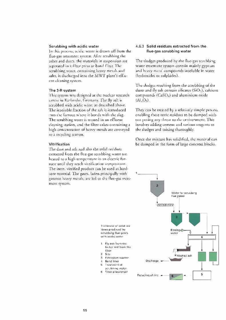
Recycling of zinc v: 1--IL... __ s _ __.
J 1 DD l
l Water for scrubbing
~;·r· --
Once the mixture has solidified, the material can be dumped in rhe form of large concrete blocks.
They can be treated by a relatively simple process enabling these toxic residues to be dumped with out posing any threat to the environment. This involves adding cement and various reagents to the sludges and mixing thoroughly.
The sludges resulting from the scrubbing of the dusts and Ay ash contain silicates (SiOi), calcium compounds (Ca504) and aluminium oxide (Ali03).
The sludges produced by the fluegas scrubbing water treatment system contain mainly gypsum and heavy metal compounds insoluble in water (hydroxides or sulphides).
4.6.3 Solid residues extracted from the flue-gas scrubbing water
55
1 Fly ash from the boiler and from the filter
2 Silo 3 Extraction reactor 4 Band filter 5 Treatment of
scrubbing water 6 Filter press/dryer
Treatment of solid res- idues produced by scrubbing flue gases with acidic water
Vitrification The dust and ash and also the solid residues extracted from the fluegas scrubbing water are heated to a high temperature in an electric fur nace until they reach vitrification temperature. The inert, vitrified product can be used as hard core material. The gases, laden principally with gaseous heavy metals, are led to the Auegas treat ment system.
The 3-R system This system was designed at the nuclear research centre in Karlsruhe, Germany. The fly ash is scrubbed with acidic water as described above. The insoluble fraction of the ash is introduced into the furnace where it bonds with the slag. The scrubbing water is treated in an effluent deaning station, and the filter cakes containing a high concentration of heavy metals are conveyed to a recycling station.
Scrubbing with acidic water In this process, acidic water is drawn off from the fluegas treatment system. After scrubbing the ashes and dusts, the materials in suspension are separated in a filter press or band filter. The scrubbing water, containing heavy metals and sales, is discharged into the MWT plant's efflu ent cleaning system.


57
The concept of rub- bish varies greatly. and in particular depends on a coun- try's level of economic development.
Unloading bay 5 Charging hopper 10 Combustion air fan 15 Water injection 20 Vats containing 2 Shredder for bulky 6 Combustion cham- 11 Post-combustion (quench) chemical reagents
waste ber chamber 16 Flue-gas scrubbing 21 Water purification 3 Waste bunker 7 Hoppers below 12 Heat recovery tower systems 4 Overhead travel- grate boiler 17 Bag filter
ling crane with 8 Slag discharger 13 Dedusting filter 18 Extraction fan grapple 9 Start-up burner 14 Heat exchangers 19 Stack
19
•
The main sections of a conventional plant for the treatment and incineration of municipal waste are as follows: • entrance zone with weight scale and refuse
rcccrvmg area • shed for tipping and storing waste co be incin
erated • incineration furnace and auxiliary equipment • thermal equipment for heat recovery and recy
cling • fluegas treatment and evacuation system • residue treatment installations • electrical installations and control system • auxiliary installations • buildings
5.1 Structure of a conventional MWT plant
T n the following, we describe only the principal clements of the MWT plant. A derailed descrip tion of all the equipment is hardly feasible in view of rhe diversity of available processes and suppliers. Longitudinal section of
a modern MWT plant
These installations are built and operated accord ing to the standards applicable to plants for incineration of domestic refuse and commercial and industrial waste similar to domestic refuse, and co installations for incinerating uncontami nated waste from hospitals and similar establish ments.
The municipal waste treatment plant described below follows a modern design based on proven conventional technology. Despite greater interna tional harmonisation of rules governing waste treatment and environmental protection since 1990, it is still impossible today to describe an international "standard" model for a municipal waste treatment plant.
5 Description of a municipal waste treatment plant

There are normally one or two additional bays not accessible to the collection lorries reserved for stacking of waste. Stacking involves transfer ring the waste using an overhead travelling crane mounted above the unloading platform co where the bunker extends into a shell but has no dis charge doors.
After registration, the collection lorries arc direct ed to rhe unloading bay, where they empty their load inco the waste bunker. The volume of che bunker is normally designed co store sufficient waste ro enable rhe plant to run seven days per week at nominal load. This is why refuse scorage bunkers need co be so large. They are able co accept excess quantities of waste even on long weekends or during breakdowns or inspections of the installations.
Controlled disposal
Recycling
[
Gypsum or HCI
Solid I residues with high pollutant content l
- Purified water
ng
-Purified flue gases
Reagents Water
l l 1• Electricity
58
Unloading and storage of waste Following registration, individuals can unload their waste in the refuse receiving area which has suitable pits, bins and storage areas. The sorted waste is generally made up of organic waste, bulky metal objects, paper, cardboard, plastic materials, glass and batteries.
Weighbridge Domestic refuse and other similar waste is broughc co che plane by refuse colleccion lorries and by individuals. Before being unloaded, the waste is weighed on a weighbridge situated at the encrance co the plane. Weighing and registration are fully automatic thanks to a rag attached to the municipal collection lorries. A registration and weighing ticker is issued for each lorryload.
5.2. 1 Registration and storage of waste
5.2 Description of principal equipment
L Tempo",. disposal
Arrival, Incineration Energy Dedusting Purification weighing and
Waste for Combustion recovery
Cooled of flue gases of flue gases
storage incineration gases flue gases
["''" - ls,,, l Dusts !Sc,obbl iron, glass. Fly ash water paper
Composting of Slag Treatment Scrubbing water • Water
organic waste treatment ,- of ashes and Acidic water cleaning dusts
I
Recycling
Jsmp iron
Recycling
Generation
1~----- of electricity
Water Steam
j 1 Air
j
Schematic diagram of the various treatment stages in an MWT plant
Recycling
j

Feeding device The furnace is fed by a feeding device with alter nating and controlled movement cycles, running on a horizontal table situated at the bottom of the feed chute. le works continuously, feeding waste without manual intervention thanks to the combustion power control system. The cycle rime, length of travel and speed of the hydrauli cally activated ram feeder can be controlled depending on the quality of the fuel (Hu of the waste) and the desired thermal value (steam pro duction).
Furnace feed The waste materials automatically ripped into the furnace charging hopper fall by gravity into a feed chute. This chute muse be permanently filled with waste to seal off the furnace combus tion chamber from the refuse pit.
The incineration furnace basically comprises a waste feed system, a combustion grate, a combus tion chamber, a combustion air system, a slag discharger system and hydraulic control systems.
5.2.2 Incineration furnace
Large or bulky items of waste (wooden doors, bedsteads, mattresses etc.) are tipped into a spe cial hopper situated in the tipping area. So as nor to disturb rhe loading and feeding of waste to the furnace, these bulky items are first shredded with a shear positioned in such a way that it can be fed by the overhead travelling crane, and the shredded waste is then fed by gravity down the chure into the main pit.
59
An overhead travelling crane normally comprises two transverse beams, a trolley which runs along these beams and a grab bucket called the grapple. The operator loads the grapple and carries out the stacking operations manually. The furnace feed hoppers are filled automatically as soon as the grapple has picked up its load. MWT plants are equipped with at lease C\l\TO overhead travelling cranes. The second emergency crane remains idle in the station situated at the end of the bunker.
After being tipped into the bunker, the waste is picked up by the grapple of the overhead travel ling crane, which usually operates semiautomati cally.
To avoid dust and unpleasant odours escaping outside, a slight vacuum is maintained in the refuse storage pit by extracting the combustion air required for the furnace.
The waste is mixed together by the grap- ple attached to the overhead travelling crane before being dropped into the inci- nerator's feed hopper.

Hydraulic plant A hydraulic plant supplies the jacks actuating the ram that feeds the furnace and the mobile bars of the combustion grate. Even in an incineration plant without automatic combustion control, it is possible co auromate the speed of the alternat ing movement of the grate and of the ram feeder by defining simple parameters such as combus tion temperature and the thermal load of the fur nace.
Hoppers under the grate Chambers shaped like inverted pyramids are situ a red under the combustion grace. These recover the ashes and other products that fall through the gaps between the grace blocks. Also, it is through these hoppers or chambers chat primary combus tion air is injected under the grate.
Since the temperature in the combustion cham ber is maintained at around 900°C, the grate blocks made of refractory cast iron have an oper ating temperature in the region of 200°C. To avoid highcemperacure corrosion damage, these blocks are cooled from the outside by the com bustion air and are protected from heat radiation in the combustion chamber by the layer of waste on the grate (the refuse bed).
To ensure com piece combustion of the waste and of the gas products in all phases of the incinera tion process, the following basic parameters muse be respected: • the waste must remain in the furnace for a suf
ficient period of time (approximately 45 min utes);
• the combustion temperature must be sufficiently high, i.e. between 850°C and l,050°C;
• turbulence muse be created in the posecombus tion zone by the addition of secondary air to ensure complete combustion of unburnt mate rials in the gases.
60
Before falling as char into the slag shaft situated at the end of the grate, rhe waste undergoes suc cessive phases of drying (by contact with the combustion gases, the hoc air injected under the grate and by the heat radiated from the combus tion chamber), degassing and gasification (decomposition into volatile and mostly com bustible materials), and combustion.
The interior of the com- bustion chamber of a grate furnace prior to cladding with refractory brickwork. You can see the walls of the boiler and the secondary air injection nozzles.
Combustion grate (Von Roll reciprocating grate) The mechanical grate is the central component of the furnace. Each grate is made up of alternat ing fixed and moving bars. Hydraulic jacks pro vide alternating travelling motion at low ampli tude to the bars causing the waste to progress along the grate.

Start-up and booster burners In Europe, every new incineration plane is equipped with booster burners. To comply with current European standards, the burners musr be activated during the startup and shutdown phases so as ro ensure a minimum temperature of 850°C when waste is present in the combustion chamber. Furthermore, these burners automati cally ignite when the temperature falls below 850°C during normal operation.
Note on the scaling of the furnace: The furnace is sealed off by the hoppers under the grates and the slag shaft which extend into the water of the slag remover, thereby creating a hydraulic seal and enabling the furnace co be placed under a vacuum by the Auegas extractor fan. The feed hopper is sealed by the plug of waste.
61
Slag discharger Once combustion is completed, the incandescent slag runs off the end of the grace via the slag shaft into a metal channel filled with water and equipped with a sloping conveyer belt. This belt moves slowly to enable the slag to drain off. This channel, called the slag removal channel, has the following functions: • cooling the slag and removing it to rhe slag pit; • scaling off the combustion chamber; • serving as a safety valve in case of excess pres
sure in the combustion chamber.
Combustion chamber As its name suggests, the combustion chamber is the part of the furnace where combustion cakes place. Combustion starts in rhe lower part above the grace and reaches a hcighc defined as rhe boil er intake. The combustion chamber is exposed co high temperatures, chemical corrosion and abra sion (caused by the slag in its lower part and the flue gases laden with solid particles above the hearth). Therefore it muse be lined with refracto ry materials resistant to high temperatures and abrasion. The lower part is normally lined with refractory bricks and the upper part sprayed with refractory concrete.
The combustion or waste at temperatures in the region of 9oo•c means the equipment is exposed to chemical attack and enormous thermal stress.

"')
- - - D
The injection nozzles are arranged at the front and rear of the furnace. They are dimensioned to ensure air penetration to the necessary depth and an optimum mixture of combustion gases.
This prevents any reduced atmosphere above che zone protected by the refractory concrete, there by avoiding the wellknown problems of boiler corrosion in the furnace.
Boch the air system and the hearth must be designed in a way that ensures intense agitation directly above the refuse bed, resulting in rapid decomposition of those gases which have nor been completely burnt, particularly carbon monoxide (CO).
Secondary air system The secondary air is injected at high velocity above rhe refuse bed in the narrow section of the hearth. Tes purpose is to ensure complete com bustion of the volatile components escaping from the furnace.
62
Three-pass vertical boiler 5 Superheaters 6 Evaporators 7 Economiser 8 Steam drum 9 Flue-gas output to
filter 10 Ash hoppers
Incineration furnace: 1 Combustion cham-
ber 2 Combustion grate 3 Feed chute 4 Hoppers under
grate
Longitudinal cross- section of a grate incin- eration furnace/boiler
To prevent molten slag (ac 900°C) adhering to the side walls of the combustion chamber and so as not co disturb the advance of refuse on the grate, pare of the combustion air can be injected via perforated refractory panels fitted on the side walls of the furnace.
Primary air system The primary air is extracted from the refuse stor age bunker to prevent unpleasant odours escap ing and causing a nuisance to the surrounding neighbourhood. The air is then blown into the furnace via the grate blocks. To facilitate combus tion of waste with a low Hu, the combustion air can be preheated in a steam air rchcarer before being injected into the furnace.
Combustion air system The combustion air system comprises two sub systems: Primary air system: provides both combustion air for incineration on rhe grace and cooling air for the grate blocks (and for the side walls of the fur nace next co the grate, if necessary). Secondary air system: ensures complete combus tion of the combustion gases.

12 13
rr: I
63
6 ~14~ ~~
J_J
I
3
7
The steam is led from the steam drum to the superheaters in order co raise it co its operating temperature. The pressure of the steam is held constant by the aircooled condenser.
Before being introduced into the steam drum by the feed pumps, the dernineralised water from the feed tank passes through the economiser, whose temperature is raised to a level slightly below evaporation point. In the economiser, the water circulates in the opposite direction to the Hue gases.
chis. This is where water/steam separation cakes place via the bank of cubes in the main body, the evaporators and the connecting pipes.
This steam generator is normally designed as a natural circulation boiler, either of the vertical threepass type or of the horizontal f\\lopass type. Depending on size, the cwo passes of rhe boiler may be equipped with an economiser, evaporator bank of tubes and superheatcrs, The main body of rhe boiler is a selfsupporting rigid tubular assembly which rests on a frame. The walls of the boiler arc made up of welded gilled pipes chat form a membrane, i.e. a totally sealed channel. The evaporating system, using natural circulation, has rhe sream drum situated above
A steam generator situated above the furnace recovers the thermal energy contained in the combustion gases, cooling them co around 200°C.
5.2.3 Boiler and thermal equipment
1 Feedwater tank 2 Boiler feed pumps 3 Boiler 4 Economiser 5 Steam drum 6 Superheater 7 Tipper 8 Air-cooled conden-
ser 9 Condensate vessel 10 Condensate pump 11 Turbogenerator 12 Heat exchanger 13 Hot water circuit 14 Primary air re-
heaters
Schematic diagram of the thermal equipment in an MWT plant

Depending on the antipollution standards in force in che country where the MWT plant is built, the installation may also include a denit rificarion system (SCR or SNCR) and a bag or activated carbon filter to improve the overall fluegas treatment efficiency, and to intercept dioxins and furans.
Flue-gas scrubbing plant (Von Roll system, see also page 48) The gas scrubbing system comprises a quench for precreacmenc of gases (cooling by injection of water) and a scrubbing tower which has between 2 and 5 treatment stages in which the following can be separated: • gaseous pollutants such as HCl, HF, 502 • ultrafine dusts and heavy metals in the form of
aerosols.
Electrostatic precipitators arc highly efficient at separating dusts, removing more than 99.9%, but they are not able to capture gaseous pollu tants such as hydrochloric acid (HCI), hydrogen fluoride (HF), sulphur oxides (S02), nitrogen oxides (NOx) and aerosols. These substances have to be removed in the fluegas scrubbing installation situated downstream of the filter.
Electrostatic precipitators The flue gases entering the electrostatic precipita tor pass through a powerful, highvoltage electric field in which che particles of dust are electrostar ica.lly charged and arc deposited on precipitation plates and then fall into dust hoppers. The plates are periodically struck in order co remove adher ing dust. Electrostatic prccipitators normally comprise two or three electric fields.
64
Dust removal from combustion gases After being cooled in the boiler, the combustion gases pass through a filter in which at least 99% of the fly ash is removed. Eicher bag filters or electrostatic precipitarors can be used.
5.2.4 Flue-gas treatment system
The steam produced is normally supplied co a turbogeneracor to produce electricity. Depend ing on the needs and configuration of the plant, condensation turbines or backpressure turbines may be used if part of the energy contained in the steam is to be utilised for hot water produc tion or for an industrial process.
In horizontalpass boilers, the convection exchange surfaces are kept clear by a mechanical device which strikes the side walls. In rhe case of vertical pass boilers, rhe surfaces arc swept free by compressed air or steam.
The risks of corrosion are in principle eliminated by a suitable choice of materials and by the lay out and geometry of the boiler componenrs. These have to be optimised on the fluegas side by performing tests on scale models in the labor acory.

Treatment of scrubbing water The main phases of treatment arc neutralisation, flocculacion, precipitation and decantacion. Heavy merals may be removed from the water mechanically with a filter press or a band filter. The filter cakes arc regarded as roxic waste and the treated water may be discharged into the sew erage system after adjustment of the pH and the tempera cure.
This cascade system of fluegas scrubbing pro duces a concentration of pollutants in the scrub bing water of the first stage of the cower. Part of chis water is drawn off to be treated in an cfAu ent treatment plant.
The stages of the scrubbers are separated by de misters which prevent droplets of water being carried along by the flue gases.
certain heavy metals and ultrafine dusts arc sep arated in the final zone of the scrubbing tower which is equipped with a ringjet (Venruri) system.
65
The second stage, comprising a rower packing layer, has several functions: conditioning of gases in preparation for the following srage, thanks to the very large contact surface area of the cower packing (polyethylene brushes, see cover page), promo ring an optimum exchange of substances; the absorption of pollutants such as HCl and HF and, where necessary, neutralisation of S02 by the injection of caustic soda (NaOH). Aerosols,
The first stage of the scrubber acrually consti tutes the water reservoir of the quench circuit.
Multistage fluegas scrubbing tower:
Once the dusts have been removed, the combus tion gases pass through a quench where they are cooled by the injection of water until they reach their saturation point. In this first treatment stage, pollutants such as HCI and HF are mostly absorbed by the scrubbing water.
Pretreatment of flue gases (quench):
To prevent a plume of water vapour forming at the output of the stack, the purified flue gases may be reheated in a heat exchanger.
Flue-gas scrubbing towers in an MWT plant with three treat· ment lines


67
Source: European Commission /OECD
World USA EU
Ireland Greece
Portugal Denmark
Netherlands Spain Belgium
Italy UK France Germany
Turnover in ECU bn Annual growth rate 1990 2000 in%
17.0 23.0 4.0 10.0 15.0 5.5
7.0 11.0 6.3 5.0 7.0 6.0 2.7 3.7 4.1 1 8 3.0 7.4 1.4 2.3 6.4 1.0 1.2 2.2 0.4 0.7 8.3 0.3 0.5 6.5 0.3 0.5 7.4
46.9 68.6 4.9 78.0 113.0 5.0
200.0 300.0 5.5
The problem of waste disposal cannot be solved simply by waste incineration. Incineration residues (slag) must also be treated properly be· fore being either re- cycled or disposed of.
Turnover and growth Country rates in environmental technology sectors
There is a large scope for growth in the EU member states, who, to date, have tended to ignore environmental protection. In certain industries there is likely co be strong growth in the areas of waste treatment, soil decontamina tion and ecological services (engineering, envi ronmental consultancy).
Whereas in the private sector the lion's share of investment is spent on environmental protection measures to improve the quality of emissions into che atmosphere, rhe public sector tends to invest mainly in water treatment technology and plants.
Germany is by far the biggest market for envi ronrnenral produces and environmental protec tion services. Of the ECU 47 billion invested in the EC in 1990, 36% was invested in Germany. Ir should be noted chat a substantial proportion of this investment was concencrated in the water industry, waste water treatment and solid waste treatment.
According to a study by the EC, the market with the potential for the highest annual growth rates between now and the year 2000 is the environ mental technology sector. This sector consists of about 20,000 companies employing over 600,000 people across Europe, and its annual growth rate of almost 5% ranks it eighth in the economic sectors of the EC.
6. 1 Environmental technology
6 Waste treatment costs

The investment needed to build an MWT plant far exceeds the income earned from the heat recovered from the waste. Variability is a key ele ment in the waste treatment sector. Investment basically depends on the following factors: • the requirements specified in che environmental
regulations of the country in question. The development of standards has a direcr impact on the technical complexity of installations;
• the required degree of materials separation. lf the aim is to obtain very small quantities of endresidues and a maximum amount of recy clable materials, the investment will be subsran cially higher.
• the desired level of operational convenience and reliability. The final cost will be pumped up significancly if the system includes a lot of redundancy and sophisticated operating and control mechanisms;
• the need co ensure chat the plant blends in aesthetically with its physical setting. Apart from rhe architectural design, care must be taken to prevent excessive noise and bad smells.
Adapting existing MWT plants to bring rhern into line with new environ men cal protection legi slation especially air emission controls requires massive investment, mainly for con structing fluegas rrearrnent systems.
6.2 Waste incineration costs
68
One of the obvious conclusions to draw from chis phenomenon is chat the escalating impor tance of R&D makes ic more difficult for smaller companies to compete in new markets. Attracted by the prizes, many smaller companies and engi neering offices have become involved in the development and design of new waste treatment or fluegas purification processes. However, they have noc managed co commercialise their prod ucts because of a lack of financial backing, such as rhe funds needed co construct a pilot insralla non.
This new marketing angle has obliged companies to invest substantial sums in research and devel opment. Jn big multinationals, R&D can account for up to 8% of annual turnover. As a result, companies have perfected new "green" produces or environmental technologies which have excellent growth potential.
Up until the end of the eighties, most invest rncnts in che field of environmental protection were made in the public sector, and were gov erned by standards and directives. Over time the private sector has also woken up ro che fact chat it is in companies' own interests to keep up with and ahead of trends in environmental regula tions. Furthermore, industrial conglomerates have increasingly realised chat projecting a posi tive environmental image can considerably enhance a company's growth prospects. One only needs to look at the big increase recently in the number of cleaning produces advertised as phos phatefree and biodegradable.

Quantity of waste incinerated [in%] 100 I so I sol 60 I
Some EU member states have only recently set maximum emission limits for MWT planes. Of the 535 waste treatment plants operating in Europe, only 15% or so are fitted with high performance fluegas treatment systems. Most of them only have one dust filter system, and almost 20% of these plants have no purifying system. The need to modernise the MWT plants by firring Auegas rreatrnenr technology requires investments totalling several billion ECUs.
Internationally, there is a trend for countries with limited space for landfills to resort increasingly to waste incineration. Whereas 20% of household waste is incinerated on average across the EU, chis percemage is more than 70% in Switzerland and Japan.
The total costs for running and mainraining such a plant can be as high as ECU 150 per tonne of created waste.
69
301 101 ol
10 20
Flue-gas purification 20 - 40 ~~~~~~~~~~~~~~~ Treatment of residues 10 - 25 ~~~~~~~~~~~~~- EI e ctr i ca I, control and operating systems
Item (% of total cost) Civil engineering and buildings 10 - 25 Boiler furnace and thermal systems 30 - 40
For technical reasons, building one large MWT plant is less expensive than constructing several smaller ones. In sparsely populated regions municipal and rural authorities often have co coordinate thci r waste treatment accivi ties. J n Europe the current trend is no longer co con struct one M\TI plant in each city, but to build regional cenrres capable of processing up to 400,000 tonnes of waste a year.
Given the current state of available technologies and che regulacions chat must be complied with, the average investment required is normally in the region of ECU 150 ru (excluding the price of the land) for constructing a new M WT plant capable of processing 100,000 tonnes of waste a year. A plan r wi ch this sore of capacity can serve a region of about 200,000 people.
Spain
Canada USA Italy UK Norway
Austria Belgium Germany Denmark Netherlands France Sweden Japan Switzerland
Percentage of munici- pal waste incinerated in each country
Approximate break- down of main items of total investments (excluding land) requi- red for the construc- tion of an MWT plant


Principal dangers during commissioning and operation • Lack of water in the boiler due to a leak,
human error or a fault in che control system. • Explosion in the boiler. • Fire in the fluegas treatment system with con
sequent damage to che rest of the installation caused by acidic flue gases.
• Fire in the refuse storage pit and hopper, in the cable ducts, the control room and the trans formers.
• Rupture of che pipes carrying steam and other acidic fluids capable of causing physical injury.
• Escape of inflammable substances in liquid or gas form and of combustible materials such as fuel oil, lubricating oil or ammonia from the dcnitrificarion insrallarion.
Principal dangers during construction and erection • Problems relating to transport and accidents
during unloading of bulky loads on the site. • High concentration of inflammable substances
on the site, particularly bearing in mind that firefighting facilities are ofrcn inadequate or even nonexistent.
• Insufficient measures to prevent corrosion and to protect materials scored on the site and in temporary storage areas from the effects of nature.
• Natural hazards, particularly storms, during the intermediate phase of erecting the structure and reactors.
7 .1 Dangers in the construction, erection and operating phases
71
The use of new technologies involving many disci plines such as chemistry, thermodynamics and materials science has steadily increased the risk from the insurers' point of view.
For chis co happen, the makers have had to invest considerable sums in research into new processes and new products able to satisfy ever more strin gent pollution controls.
For a long time, waste incineration plants were regarded as a source of pollution since they con sisted of little more than a furnace and a chimney stack. Nowaday, however, modern MWT plants are well accepted by the population in most countries.
The interior of a post- combustion chamber of a rotary furnace for incinerating special wastes. Settling claims relating to the refracto- ry brickwork often presents problems for companies offering engineering insurance.
MWT plant in La Rochelle, France. During the intermediate erec- tion phase, installations are more exposed to damage by storms and wind.
7 Dangers and typical damage

72
Stage pumps . gas scrubbi ,n a flue- ing tow Most of them _er. used are . fl atenals in amm b plastic T! . a le · us repre- sents an fire . aggravated
risk.
MWT plant. Finistere Fin South East · , ranee· 1• ,ng the b .1 • nstall-
01 ers W erecting th · ork on e MWTe . ment started quip- the comp! . well before civil engin:~o.n of the building ring and works.

73
Miscellaneous dangers • Deliberate damage, sabotage, strike, riot, popu
lar movements (MWT planes are still not well accepted by the population in certain regions).
• Natural hazards (earthquakes, flood, storms etc.)
• Claims incurring civil liability: pollution, phys ical injury, damage co property and intangible damage.
• Major delay in final commissioning following a claim occurring at the end of the erection phase or during tesrs. If Advanced Loss of Profits cover is held, the damage may run to tens of millions of ECUs.
Dangers associated with the technical maturity of the installations or their prototype nature • Error of design or fabrication, material defect
(risk is heightened by the rapid development of processes and technologies).
• Risk of errors in the erecting of new installa tions (the works normally have to be executed within a short time and in a limited space).
• The difficulty of establishing limits between the risk borne by the contractor and the insurable risks.
• Fire, danger to the environment and surround ing area caused by contaminated water used to extinguish the fire and by flue gases containing pollutants.
• Ice, e.g. in the boiler, the refractory lining or the water and steam pipes (particularly in the commissioning phase when the plant is not yet in continuous operation).
• Control and/or handling error due to personnel not being sufficiently familiar with the equip menr.
• Interrupted operation for a period of months or even years following a fire or total loss of a major item of machinery.
MWT plant in Frank- furt: the construction of industrial complex- es in residential areas can give rise to all sorts of claims.

Experience shows that an oxygendeficient atmosphere may have an adverse effect on the walls of che boiler cubes. The protective layer cannot form on the pipes (the layer protecting the pipes is attacked by combustion gases con cain ing CO). Furthermore, in view of the fact that these gases contain corrosive matter, namely chlorides, sulphates and sulphides, corrosion is liable co occur and will very quickly destroy the steel pipes.
Corrosion due to combustion gases in the furnace In refuse incineration processes, it is not always easy co guarantee I 00% combustion throughout the furnace. If the organic matter does not remain in the furnace for long enough, if the oxygen concentration is insufficient and if the necessary cemperacure cannot be attained, oxy gendeficient zones may occur, leading to the for mation of carbon monoxide.
The flue gases produced by the burning of waste contain gaseous acidic substances such as HCI or 502. Consequently the flue gases become highly corrosive when their temperature reaches che condensation point of these acids at around l 50°C. This means chat all systems which come into contact with the flue gases from the boiler output onwards muse either be maintained at a temperature above l 50°C or they must be cov ered with anticorrosive material. In the case of installations equipped wich a wee scrubbing system, the acids are transferred from the flue gases to the scrubbing water. For chis reason, the whole of the scrubbing water treatment system has co be made from plastic materials such as polyethylene or polypropylene.
7 .2.2 Corrosive substances and environments
74
200 I Temperature of tube wall [in °CJ ioo I
,:,;
·~ ,:: 0 'iii e 0 (.,)
High-temperature corrosion
The treatment and utilisation of solids during the processes creates technical problems, because these materials may be abrasive and they may cause fouling and blocking when they absorb moisture. ln the form of dust, they may cause explosions. In waste treatment planes, ic is neces sary co treat and handle a wide variety of solid materials such as ash, gypsum, slag, sludges, acti vated carbon, highly toxic filrer cakes ecc.
7 .2.1 Utilisation and handling of solid products
Dangers associated with the process 7.2
Wet corrosion
Corrosion curve for boiler tubes

Unwanted chemical reactions, problems with the dosing of the new and recycled lime and with the removal devices may lead co damage such as over hearing of the filter bags, corrosion of the system or mechanical rupture of the screw conveyors and equipment for removing the used lime.
In these installations, the causes of damage arc linked to the use of lime.
Fluegas treatment system based on dry or semi dry scrubbing:
Corrosion in the flue-gas treatment system The risks of corrosion vary depending on the methods used.
The fluegas ducts are kept under pressure. Therefore they must be welded to ensure they are impermeable co gases and to prevent any leaks during operation.
Corrosion due to combustion gases outside the furnace Corrosive combustion gases coming from the furnace can, in the event of excess pressure on the fluegas side, lead co severe corrosion damage if chcy escape through fissures or leaks. Tn the open air, chese gases condense, cool and form acids which attack their environment.
75
The incineration grates of waste treatment plants arc exposed co high thermal and mechanical stresses. Waste increasingly contains plastic mate rials which impose additional stress, both ther mal and chemical, on the incineration grate. A high content of waste made from synthetic mate rials causes local hocspots within the layer of waste. A~ a result, the copper, lead and alumin ium contained in certain wastes melt and enter the cooling channels where they solidify. The cooling air cannot circulate and the bars of the grate are damaged by the excessive heat. The layer of waste on the grate affects the service life of the combustion grace in two important ways: it protects it against radiation and resists the combustion air which cools the grate. Bad man agement of the i nsrallacion creates holes in the refuse bed causing localised desrrucrion of the bars of the grate clue to hightemperature corro sion.
Acidic corrosion on the external walls of a chimney stack. This type of damage can arise when the flue-gas purification system is by-passed due to tech- nical problems.

Incineration plants contain a wide variety of rotating machinery. The largest and the most sensitive arc undoubtedly the extractor fans and the steam turbine, though one should not forget the boiler feed pumps which, although small in size, are essential co the operation of the insralla non.
7.2.4 Rotating machinery
Under the standards in force in most industrial ised countries, incineration plants are only grant ed planning consenr on condition chac the energy contained in the waste is recycled. For this rea son, all new plants are equipped wirh recovery boilers which normally operate with superheated steam between 30 and 60 bar. Such planes are regarded as true cogeneration power stations, with coca I output sometimes as high as 300 MW.
7.2.3 High pressures
The dewpoint of the gases is in the range of 150 to 340°C. Experience shows chat for certain gas compositions, even at high temperatures, the dewpoinr may be below the normal threshold, causing corrosion to develop.
As already mentioned, the gases produced on combustion of waste contain, besides water vapour, ocher corrosive substances capable of condensing, such as the acids HCl and 502, which pose a major corrosion problem.
Corrosion damage may also occur in the zone of the hoc gases, where ir is impossible to recover the internal walls with rubber, or in rhe zone of the purified flue gases, where an ticorrosion pro- tection is sometimes absent.
76
To avoid corrosion, the internal walls of che scrubbing cower and che ocher parts of the instal lation are coated with rubber or ebonire. This protective coating is often permeated by the dif fusion of acidic water vapour. This can lead to the formation of pockets of acid behind the coat ing which in rum cause blistering and deep corrosion co che wall of the metal shell. The blistering is clue to a variety of causes possibly a manufacturing fault, a difference in temperature between rhe internal and external walls of the reactor, chemical influences or repairs carried our on site under adverse conditions.
Fluegas treatment system based on wee scrub bing:
The calcium chloride that is formed is very hygroscopic (present in the flue gases and thus produced by the reaction); ic may therefore become deliquescent if the temperature of the flue gases falls below 90°C, leading co condensa tion. This phenomenon causes caking and diffi culties with handling the recycled product, mainly when starting, stopping or slowing the installation.
ln theory, one molecule of lime bonds with two molecules of hydrochloric acid to form one molecule of calcium chloride and of water.
2 HCI + Ca (OH)2 > Ca Ch+ 2 H20
In the case of the dry process, for example, where treatment involves bringing the flue gases inro contact with fine slaked lime (Ca(HOh), the reaction is as follows:

Explosions caused by bulky waste Fires and explosions can occur during the shred ding of bulky waste items. Produces con rained in the waste such as gas cylinders, atomisers ere. can trigger explosions and fires in the bulkywaste shredding installation or the combustion cham ber.
Special attention should be paid during erection and maintenance operations. Many fluegas treatment systems which use wet scrubbing are internally coated with inflammable materials. One stage of the scrubbing cower contains tower packings made of plastic. These materials can easily catch fire from welding sparks, for exam ple, or because of faulty site heating or lighting equipment.
Fires in the flue-gas scrubbing system In the past, many fires have occurred as a result of plastics, coatings, rubberised materials and ocher inflammable substances catching fire.
Fires in the charging hopper Particularly in smaller installations, a fire can spread from rhe hearth co the furnace feed hop per. This happens mainly during the scareup phase, when the feed chute is halfempty, or dur ing the first tests under load, if the feeding device is not working properly.
77
Fires in the refuse bunker The storage of municipal waste in the pie poses a latent danger. The pie can be observed from the cabin of the overhead travelling crane, from where the operator can detect a fire starting as soon as smoke appears. But once a fire starts, dense smoke can spread in a matter of minutes, so char the only solution is co flood the bunker. Operators are reluctant co resort co chis solution, since it results in the total shutdown of the plant for several days.
Experience shows chat fires and explosions are today by far the commonest causes of damage in waste treatment planes. The main causes are as follows:
7 .2.5 Fire and explosion
The exrractor fans are normally situated down stream of the fluegas treatment system, because this system should preferably be kept under a slight depression to avoid any accident or exter nal corrosion in the event of a leak in a fluegas channel or in the scrubbing tower. This means that the fans operate in a damp atmosphere, since the gases are saturated with water when they leave the scrubbing rower. For chis reason, all pares which come into contact with the gases are ebonised. Dimensioning and designing these fans is a highly skilled cask. Because of the ebonising, for example, the circumferential velocity of the impeller must be limited. The most frequent causes of accident are: corrosion of the carrier material and damage to the ebonire lining by foreign bodies carried by the flue gases, and destruction of shafts caused by heavy vibration (if the fluegas treatment system is i nefficienr, dust deposits form on the fan and cause vibrations).

78
Damage to superheater tubes of a two-pass recovery boiler (Berne MWT plant) The rubes whose walls are directly exposed co the combustion gases have been eroded co the point of perforation. From a metallurgical examination and an analysis of the deposits accumula.cing on these cubes, it appears chat the wear was caused by acid corrosion (corrosion at the dewpoinr of the acidic gases). The damage suffered by che cubes, i.e. che heavy wear on their walls, was very probably clue to the combination of two types of attack: firstly, corrosion caused by sulphuric acid, and secondly erosion which wore down the sur face layer of deposits formed by the corrosion, thereby reexposing the cube wall co the corrosive agent.
An accident in the boiler of an MWT plane serves to illustrate cbe mechanisms giving rise co chis type of damage (corrosion of combustion chamber tubes by hot gases, erosion of evapora tor tubes), and gives an idea of the disastrous consequences. These include not only the cost of replacing the damaged tubes, bur also the costs of temporary storage, transport and incineration of municipal waste at another site while repairs are being carried our and the loss of income from sales of steam, hot water or electricity.
The greatest danger, in the event of a leak, is that the cubes of the combustion chamber will no longer be cooled. They can only be cooled with water under certain conditions, and since it cakes between 15 and 30 minutes to extinguish the hearth, these cubes are exposed to very high ther mal stress. In most cases, chis overheating leads to severe deformation of the uncooled cubes which constitute the walls of che first pass of the boiler.
Tc is common for the cubes of a steam boiler in a waste treatment plant to become damaged. How ever, in the event of a leak, a large volume of water vapour can very rapidly spread within the boiler, seriously damaging the refractory com pound inside the combustion chamber.
The combustion gases contain large quantities of very fine solid particles. Therefore the tubes of prehearers, superhearers and evaporators arranged perpendicular co the Aow of gases arc subject to greater or lesser degrees of erosion (comparable co fine sandblasting). The severity of such ero sion mainly depends on the nature of the solid particles and the flowrate of the combustion gases.
Possible damage to steam boiler tubes in munici pal waste treatment plants.
7 .3 Typical damage
Damaged refractory brickwork (shot con- crete) on the walls of the combustion cham- ber, made up of boiler tubes.

I :11111111111111~111!11 ~llljllllllllllllll~II 0 11 1 1 1 I 1111 Ill lllllilll :IIJlilll lllliUllrillllllH ill
79
ln the combustion chamber, unprotected cubes undergo considerable oxidation and corrosion. The thickness of their walls diminishes by approxi marely 1 mm per month. This is why the entirety of the refractory compound must be checked regularly (every three ro six months). This is an important and effective precaution against damage. On the other hand, ic is nor always easy ro detect damaged areas of th is com pound, due to the accumulation of soot and incandescent slag. Any identified damage must be repaired immediately by specialists.
The corrosion process described above can only cake place if rhe temperature is below che dew poi nt of the sulphuric acid. The dewpoint of gases containing wacer vapour and sulphuric acid is theoretically between I OO"C (the dewpoinr of water vapour) and around 340°C (dewpoinr of pure sulphuric acid). The relatively large quantity of sulphates contained in the combustion gases suggests a high concentration of acids; in the present case we can estimate that the temperature of the tube wall was between 250 and 300°C. Such low temperatures are unusual in che latter pare of the second pass.
Corroded tubes from a boiler's superheaters. These tubes, which are not protected by refractory brickwork, are extremely exposed to corrosive and abra- sive combustion gases.

* only possible in conjunction with Contractors' All Risks or Erection All Risks cover.
The construction project for an MWT plane usu ally cakes the form of a turnkey contract between rhe clienr who commissions the project seldom a private investor bur more likely to be a group of several can cons, a syndicate of local authorities or a large municipality, etc. and the project manager, who is usually a general contractor. The works involved in the construction, commission ing and operation of the plant carry diversified risks both in terms of their size and nature. In addition, many different professions and busi nesses are involved in the project, including: • engineering consultants • archicccts • regulatory bodies • different companies acting as a consortium • a general contractor employing subcontractors,
who in turn use their own subcontractors and suppliers.
8.2 Main project stages in the construction of an MWTplant
Operational cover • Machinery Breakdown (MB) • Machinery Loss of Profits (MLOP) • Computer All Risks • Boiler Explosion
Preoperational cover • Contractors' All Risks (CAR) • Erection All Risks (EAR) • Advanced Loss of Profits" (ALOP) • Contractors' Plant & Equipment (PLEQ)
The most common engineering insurance used for waste treatment planes can be divided into two distinct categories:
8.1 Main forms of engineering insurance
81
This chapter is designed co help underwriters analyse the facrors affecting the construction or operation of an MWT plant. For a full descrip tion of engineering insurance, please refer co Swiss Re's specialised publications.
Insurers, for their pare, must be able co support their clients in rhe development of new products, offering chem insurance conditions chat are tail ored exacrly tO their needs bur without jeopardis ing insurabiliry.
In chis context the insurance industry muse, as always, strive co lend its support to society and, in particular, co its industrial clients that require cover for all types of risk. The main characteris tics of MWT plant construction projects arc their complexity, which makes interdisciplinary skills essential, and the high political and finan cial stakes. Companies face a series of problems if they are co fully satisfy the increasingly demand ing requi rcrnenrs imposed by environmental laws.
The previous chapters have shown that iris per fectly feasible to install systems char provide effi cient waste management and disposal bur which are also rorally environmentally friendly. This implies, however, char all the parties concerned (public authorities, households, industry and commerce) are willing co make an active contri bution.
The face char environ mentally responsible waste management and waste disposal has become a growing concern in recent years in industrialised nations undoubtedly has many positive aspects.
Not many people are really aware of the vast amounts of waste we produce. To pre- vent us all being bur- ied under our own rubbish, efficient waste management and waste disposal systems must be put in place.
8 Engineering risks associated with the construction and operation of an MWT plant

82
_______ w_o_r_k_s_+_E_re_c_ti_o_n l Tests i Maintenance -!
Separate branches Pre-operational cover Operational cover
- Transport - Contractors' All Risks (CAR) - Machinery Breakdown (MB)
- liability · Erection All Risks (EAR) - Machinery Loss of Profits (MLOP)
- Contractors' Plant & Equipment (PLEQ) · Computer All Risks - Advanced Loss of Profits (ALOP) · Boiler Explosion
r- I I I I I I I I I
Q) Erection i Tests Maintenance ~ I "' ! >
Activities Duration in years
Order of service/building permit ·~ Civil engineering/building works
Erection of equipment
Works completion report ,. Commissioning/tests
r .. Semi-industrial production
Performance tests • Provisional acceptance (list of outstanding problems) It 1 - 2 years
Warranty period
Final acceptance (rectification of outstanding problems) '~ 1 2 3 4 5
Excavation, laying out and foundation works The initial laying out and excavation work on the building site can start as soon as the conrracror receives written instructions. The sice chosen for che new M\X7T plane is often on the outskirts of a town, in an industrial zone on poor terrain (old landfill, swampland, erc.), To this end the soil often has co be compacted or foundation piles need co be driven in or implanted with a vibrat ing compactor, to ensure even load distribution and a stable structure.
8.2.1 Civil engineering and building works
Engineering insurance during the construe· tion and operation phases of an MWT plant
It is essential char the insured parties (the client and the contractor) have insurance cover that is tailored to their needs during every phase of con struction and operation. The technical risk often represents a large proportion of the whole risk, but other hazards, such as fire, natural phenome na and civil liability muse be taken into account as well.

Work usually commences by erecting the steel structure of the furnace/boiler unit at ground floor level. Once assembled, the boiler and the furnace constitute a single element, which is also the heaviest and bulkiest piece of equipment in the whole plant (it can easily be 30 m high). The furnace/boiler and other vital components (reactors, filters, air condenser, erc.) are trans ported to the site in separate sections in special convoys. Any handling operations (unloading, hoisting, mounting) also require heavy lifting gear.
As long as there are no exceptional problems with civil engineering and building works, a start can usually be made on erecting the equipment about 12 months after the construction site opens.
8.2.2 Erection of equipment
The civil engineering and building works phase does not end until the client provisionally accepts the MWT plant. Although a substantial percent age of the works are complete by the time the erection stage starts, painting, metal work and external. landscaping continue up to the end of the project.
T n the evenr of a serious accident this design can also have unfortunate consequences because it complicates access re; some equipment, making it more difficult to dismantle and reassemble. So repairs take longer, adding to the final cost of the loss. Another negative aspect, from the insurer's point of view, is the catastrophic impact that a fire can have inside a building, because pollutant and corrosive gases can cause serious damage to a large proportion of the installations.
Greater care is usually taken with the architectu ral design of the building, to ensure that it blends in with its surroundings. These constraints on the building design slow clown construction, firstly because the building work takes longer and overlaps with the equipment erection phase, and secondly because it is so metimes difficult co install large components such as the boiler or other bulky machinery in the building.
83
The second rype of building is intended for M\X!T planes located near residential areas. Here the external design is completely different and its cost can amount to more than 25% of the cost for the entire plant. All the equipment is housed inside the buildi ng, which is a robust watertight structure made entirely of reinforced concrete so as to keep down noise pollution and odours.
The first is to sire MWT plants away from built up areas. In this case the building has a simple design and is limired to a furnace/boilerhouse, a control room and administration and out buildings (offices, meeting rooms, changing rooms, workshops, canteen, erc.). The fluegas treatment system and residue treatment systems are not covered over. The whole construction is made of reinforced concrete and is no more than one or two storeys high. The rest is built as a steel structure clad with panels.
Buildings There arc two general trends:
An MWT plane generates a lot of traffic. Tn addi tion to the supply network inside the plant (roadways, parking, access ramp to the unloading shed, manoeuvring zone for trucks, erc.), access roads to the MWT plant also have to be con structed or upgraded.
Another point to bear in mind about the con struction work is chat more and more countries are now insisting that the site has a waterproof barrier to prevent pollution contaminating the soil, rivers and groundwater. For this reason, the drains for collecting rainwater, waste water and water used co extinguish fires must be fed into a retention basin based on the "Schweizcrhalle" model.
The refuse storage bunker, whose effective vol ume can be as much as 20,000m3, is usually con structed below ground level. Quire often there is a groundwater table. Alrhough it is not that diffi cult to ensure that the bunker remains water proof while the plane is under construction, the bunker could turn out to be a sensitive issue in the decennial guarantee.

During the fine-tuning period, which must not exceed 2 months, the contractor can stop the plant or run it under different regimes, for the purpose ~f making any adjustments required and ensuring that the plant operates at maximum efficiency. Prelimi- nary testing is perjormed separately on each item of equipment. Tests are carried out under the supervi- sion and at the expense of the contractor. They are designed to check that all the mechanical, electrical, electronic, thermal and hydraulic equipment func- tions correctly and satisfies the relevant norms, cur- rent standards of professional workmanship and the operating conditions prevailing in the market at the time.
Fine-tuning the plant No later than two weeks after the issue of the works completion report, the contractor will start to fine- tune the plant, having first given the project man- ager written notification of this.
After completing the inspection the project manager wi!L draw up on site a works completion report which both he and the contractor must sign. This report will provide details of omissions, impe1fec- tions or defects discovered (if any). The contractor must rectify these as soon as possible.
Within one week of the date Jpecified by the con- tractor, the project manager will inspect the plant to check that everything has been properly executed and complies with project specifications.
Works completion report The contractor provides written notification to both the contract manager and the project manager of the date the works are expected to be completed, with at least one month's notice, and will keep both parties inj,Jrmed by issuing a provisional weeldy schedule indicating the approximate waste volumes that the plant will be able to handle during the fine-tuning period.
84
Even experienced underwriters sometimes find it difficult to decipher the contractual documents and pinpoint the exact duration of the various operations that take place during chis delicate period. We found it worthwhile ro refer to many of the definitions provided in the French version of the Schedule of Special Technical Clauses (CCTP) relating to rhese activities. Obviously rhere may be variations between different coun tries, but the overall chronology of events is very similar.
The period between the completion of the erec tion phase and the client taking possession of the plant is very important for insurers of engineer ing risks. In the case of an Erection All Risks pol icy, capital exposure is at its greatest once the works have been completed. The consequences of a fire, for example, could be disastrous. Further more, it is during chis period chat the first tests under load are performed on the machinery, and it is obviously the time when most of the design and erection errors come to light, 'along with any material defects, etc. If Advanced Loss of Profits cover has been taken out, chis is a critical phase in the project, because cover expires on the same date as the provisional acceptance of rhe plant.
8.2.3 Commissioning the plant
Towards the end of the project, when all the fin ishing work is in progress (pipework, electrical wiring, hear insulation, metal gantries, paint work, etc.), there may be several hundred work ers on site. This undoubtedly poses an aggravated risk as far as liability is concerned, and physical injury is certainly noc uncommon at chis scage of the operations.
To cut down the surface area of the MWT plant, thereby reducing its cost, the fluegas treatment system is nor installed ar ground level as a con tinuation of the incineration line, but on a raised platform within the building. This can pose a slightly aggra vared risk in terms of Erection All Risks cover, because the reaccors, ft 1 tcrs and chimney stacks are more susceptible to storm damage while being erected.

The client, or any agent appointed by him, is responsible for supplying, installing and removing any temporary devices required to perfi>rm the tests.
If a test control body needs to be called in at any time, the client will bear the cost.
The tests involve the incineration, under a constant regime and for a specific number ofhours, ofa quantity of pre-weighed waste that is as close as possi- ble to the tonnage processed at nominal and mini- mal capacity. The nature of the tests and their frequency, as well as the timetable for performing them, are mutually agreed by the contractor and the client, taking into account all the operating possi- bilities and exigencies. During the test period the contractor and the operating personnel supervise the plant's operation.
The purpose of these tests is to determine the nomi- nal and minimal treatment capacities, the treat- ment quality, the consumption and output of the different equipment under industrial operating con- ditions.
Acceptance testing Acceptance tests are performed once the industrial- scale trial is complete.
Plant management up to acceptance Until the point of acceptance, the plant is managed under the supervision and responsibility of the con- tractor: • All the fine-tuning, repairs or modifications
required are carried out under his supervision and at his cost.
• Energy, liquids and other consumables are provid- ed ftee of charge by the client in limited quantities that satisfy the plant's requirements as defined in the provisional operating assessment. Nevertheless, the contractor is responsible for operating the plant, and will cover the cost of this, from the date that the operating contract comes into force.
• The contractor will pay the wages of the operating personnel.
85
The contractor will supply the project manager with operating and maintenance instructions, the plans of the plant and will provide details of adjustment and safety parameters.
industrial-scale operation lasts for 2 months, on condition that it includes a minimum operating time for the installations, or the treatment of a minimum quantity of waste stipulated in the Schedule of Special Technical Clauses.
No later than two weeks after this date the project manager must, unless there is a valid objection, release the plantfor industrial service. This will be confirmed by an on-site report drawn up by the pro- ject manager and signed by him and the contractor. The date of commissioning is the date the report is signed.
When the contractor believes that the plant is ready to commence the industrial-scale operation it was designed for, he gives written notification to both the contract manager and the project manager of the date when this can start.
The purpose of this phase is not to verify the plant's performance characteristics - these are measured during acceptance testing - but to check that the installation functions without any mechanical, thermal or electrical faults and without any other operating problems.
Semi-industrial production This phase is when the plant enters into service under normal operating conditions, with the client regularly transporting waste for incineration.
in addition, the constructor of the plant will check the efficiency of the various treatments (operation at nominal and minimum furnace capacity, efficiency of flue-gas treatment, quality of the slag, etc.). Whatever happens, the plant must come on stream at the end of this period.

This responsibility must not indeed cannot be transferred to the insurance company. It is therefore up to the contractor to take every appropriate measure co avoid any loss event, even
One of the principles of our economic system states that anyone pursuing an economic activity must, within the limits of their capabilities, meet any obligacions ensuing from their activities.
The business risk is an unpredictable peril which cannot be mathematically calculated; it relates co dangers that are inherent in the commercial risk.
8.3 Comments on the business risks
These constant thirdparty interventions during the industrial operation of the MWT plant rep resent an aggravated risk in the event of a loss (fire, explosion, machinery breakdown, physical injury, etc.).
During this period, which is in fact the period of warranty provided by the contractor and his sub contracrors, the latter often visit the site regularly to fulfil their contractual obligations: rectifying outstanding problems, finetuning processes and adjusting machinery, as well as performing repairs.
The first year of industrial operation is tricky, firstly because some of the machinery has not been fully run in and there arc often teething problems that disrupt the plane's operation, and secondly because rhe operator has not yer acquired enough experience co fully master the equipment.
Once acceptance testing is complete and the results are conclusive, the ownership of the plane transfers to rhe client. The client and rhe plant operator arc then responsible for plant manage ment. The operating personnel have been trained and have had rhe opportunity to familiarise themselves wich the installations over the C\VO-
month industrial operation phase, under the guidance of the project manager's skilled person nel.
8.2.4 Industrial operation
86
( 1) acceptance of the works takes effect on the date that the plant begins industrial operation.
Works completion does not imply that all the finish- ing work has been done, especially external land- scaping (access routes, green spaces, fencing, etc.) and any works that are best performed after certain tests are over (painting. insulation, etc.).
The sequence of events leading up to the acceptance of the plant is illustrated in the following table: • The contractor provides written notification to
both the contract manager and the project manag- er of the works completion date
• Date of works completion indicated by the con- tractor
• Works completion report indicated by the project manager
• Start of the fine-tuning period • Contractor requests that the plant enters indus-
trial service • Project manager draws up report on the plant's
industrial operation phase • Works completion date (J)
• End of industrial operation phase and start of acceptance testing. Once testing is over, the accep- tance is confirmed and the works completion date OJ is fixed by the client at the suggestion of the project manager.
• Client takes possession of the plant • Additional acceptance testing, rectification of out-
standing problems.
If the results of the tests are disputed, an officially approved test body will be commissioned to perform another series of tests. The cost of the second batch of tests will be borne by whichever party the final results prove to be wrong.
The liquids and other consumable materials needed for the test phase are provided free of charge by the client in quantities limited to whatever is needed
for the plant to operate while testing goes on.

One of these borderline cases involves providing cover for rhe consequences of a material loss caused by a design fault, poor execution of works, or a material defect in the prototype installations. This limit is sometimes even exceeded when the insurer agrees to pay che cost of repairing the faulty part.
"What are the risks char I can cover without exceeding the point where l take the contractor's place?" The essential role of the contractor is to run risks inherent in every industrial and com mercial undertaking (research and development into new produces, production, sales, erc.) with the aim of assuring the success of his business. If che insurer is encouraged to cross chis barrier, should he not automatically share in the profits generated by his client's activity?
Among the differenr types of engineering insu rance cover there arc a number of borderline cases where the insurer faces the following dilem ma:
Given these circumstances, an insurer who offers conventional cover, or perhaps slightly extended cover, is inevitably confronted with the same problems as his client, i.e. having co provide cover for risks of an entirely innovative nature.
Tn view of rougher environmental legislation and fierce competitive pressure, rhe contractor is obliged co assume new risks which are becoming more and more onerous. In addition, regulations are still at the evolutionary stage, which makes the cask of constructors and investors even more difficult. Frequent announcements of revolution ary processes on rhe marker also increase the pressure on contractors.
they can meet. The time taken co perfect new processes or equipment has had co be drastically cue. A good many produces are not able to be properly rested until they enter industrial service, with all the risks and surprises this entails.
87
Contractors have had to make enormous efforts co keep up wi ch the frantic pace of technological progress. They have accepted contracts with per formance guarantees which they are not cerrain
The sudden escalation of environmental aware ness and pollution controls has encouraged rapid technological advances over the lase decade or so. Whereas in the eighties waste incineration planes in most countries were practically limited to a furnace, a filter system and a chimney stack, nowadays these installations are based on a whole range of hightech processes designed to produce "zero" pollution. Furthermore, cogeneracion plants fuelled by biogas, waste sorting and recy cling planes, pyrolysis or plasma furnaces should all help co reduce environmental pollution to a rmrurnurn.
in the field of engineering insurance, the expres sion "business risk" is often accompanied by the attribute "uninsurable". Ir is certainly difficult to draw a clearly defined line between the pure business risk and insurable risks. The role of a company char offers engineering insurance is to protect the insured against the economic conse quences of a material loss caused by a sudden and unforeseen event over a fixed period. The insured is nor in a position since it is nor his job to satisfy the demands of the constructor who wants to protect himself from the financial consequen ces of conrracrual guarantees that extended in the course of his business activities. But in the envi ronmental technology sector these sorts of demands do sometimes occur.
The business risk is influenced by subjective fac tors such as the level of competition, che search for new markets, the development of new prod ucts, expertise in the sector of activity and the tendency co take financial risks in relation to acquiring new business.
if he incurs additional cos rs in doing so. The role of the insurer is to assume responsibility, within well defined limits, for losses which, despite all the precautions taken, occur as a result of sud den, unforeseeable and accidental events.

The choice of suppliers and subcontractors plays quire a significant role in che quality of the pro ject. Equipment such as electrostatic precipita tors, bag filters, activated carbon filters, caraly sers, steam turbines, extractor fans, etc. are also key components in che treatment line. Damage or malfunction in any one of them will inevitably cause a serious delay in the commissioning of the MWT plant.
This question is equally applicable to designers and construccors of the principal equipment (fur naces, boilers, fluegas treatment systems, caraly sers, residue treatment systems, ere.). Municipal waste is a very heterogeneous mix of combustible materials that constantly brings surprises in the combustion process and subsequently in the composition of the flue gases. Extensive experi ence is required to be able to master all the com plex techniques involved (choosing the right materials, dimensioning chc equipment correctly, defining the control and operating systems, etc.). A high degree of rheorerical and practical exper tise in complementary technologies is certainly an important factor but in itself does nor general ly entail a complete mastery of the subject from the outset. A leading international constructor in this field believes that a specialist in chis industry must allow at lease 6 years between the concep tion of a new produce and its industrial commer cialisation.
Docs the contractor have sufficient experience in this domain? How many similar MWT installa tions has he already completed?
When performing a risk analysis of new business, we recommend chat underwriters pay special attention to the following aspects:
rares shown in the tariff guides are based on experience co dace and therefore need to be adapted to reflect specific parameters. Even for experienced underwriters, ic is difficult co evalu ate the true price of the risks inherent in this cechnological evolution. Furthermore, fierce competition between insurers is a dominant fac tor, so that che prudence generally advisable for risk assessment often takes second place.
88
New treatment systems and processes are being continuously developed by industrialises, and are advancing much more rapidly than che premium rating cools available to underwriters. In this respect, it must be pointed our char rhe premium
Modern waste treatment planes are complex installations, which makes risk analysis and pre mium rating difficult. From a technical view point, these installations can be grouped, in cer tain respects, in chc same class as power stations and may also present similarities with facilities found in the chemical and petrochemical indus try. le is not easy for insurers to evaluate with suf ficient accuracy che technical problems and the claims potential inherent in each new business, so as ro take these into account when pricing the risk and formulating the insurance cover. In our opinion underwriting chis class of business requires dose collaboration between insurers and their clients.
8.4 Underwriting recommendations
ln order to cover the consequences of these guar antees not being met, the client fixes contractual penalties which can be as high as ten percent of the total market value. Furthermore, the client may even refuse co accept the installations.
Contractual guarantees accepted by the contrac tor on signing the contract are typically business risks that cannor be transferred to the insurer. Examples include: • Performance guarantees relating co production
capacities, output, electricity consumption, and other consumable materials (water, chemical reagents, etc.), operating parameters (pressure, temperature, throughput, erc.), noise pollution, emissions, etc.
• Product guarantees (granulometry, water con tent, resistance to corrosion and hear, insulat ing properties, appearance, colour, toxicity, etc.)
• Guarantees of availability and reliability • Meeting deadlines for completing the works
and commencing industrial operation • Any other guarantee contained in rhe contract
that is particular to a produce, a piece of work, or a service.

One of the interesting engineering insurance aspects con necced with this class of business is risk analysis and underwriting for Advanced Loss of Profits and Machinery Loss of Profits policies. Encouraged by their financial backers, clien cs who commission MWT planes are now showing a greater interest in taking our these types of insurance policies.
Apart from the engineering risks just described, the plant's exact geographical location also plays an important role, both as regards geological and weather conditions, such as whether it is: • in an earthquake region • directly on the coast • in a region that experiences heavy storms • near a water course or in an area susceptible to
flooding • built on poor terrain (old landfill, hardcore,
swamp, etc.)
The list would be incomplete without looking at protection against fire during the construction and operation phase. Solely on the basis of major fires that have broken out in fluegas treatment systems in recent years, the premium needed to cover chis class of business (Erection All Risks) has robe significantly higher than the premiums currently encountered on the market. Given the difficulties involved in scccing a premium that reflects the risk, it is absolutely viral co impose fire prevention measures in the special conditions of insurance policies (for more information, please refer co Swiss Re's pub I icacion "Fire protec tion on building sites"). These conditions must be verified by regular site inspections.
ogies are only jusc being introduced. In this respect, it is interesting to note chat loss preven tion is one of the services offered by insurance companies chat is often appreciated by clients. In a good many cases loss prevention benefits not only the insurer, but primarily che owner and the operator of the plane, because financial losses fol lowing material damage are only insured in very rare cases and can jeopardise the company's very existence.
89
le is important co remember that these experiences apply almost exclusively to countries such as Germany, Switzerland or Sweden, where the con struction of highperformance fluegas treatment systems commenced several years ago. It would be unfortunate if the same errors were co be repeated in ocher countries where these tcchnol
Obviously a lot of negative experiences have been recorded as a result of these problems, which it must be emphasised were in each case caused mainly by deciding co run a risk in order co reduce che overall cost of the M\VT plane.
The positioning of certain equipment also requires careful checking. For example, the catal yscr muse normally be installed downstream of the fluegas treatment system to prevent it from becoming prematurely fouled (remember chat the catalyser operates at temperatures around 350°C and therefore requires a source of ener1:,ry co rehear the flue gas). Positioning the catalyser upstream of the fluegas treatment system, i.e. before the gases are cooled, muse be avoided at all coses. Tc should also be noted chat, as far as the process is concerned, other equipment can be installed in positions chat are unsuitable purely on grounds of economy. One example is the exrracror fan, which is positioned in a hoc area so char it docs nor have co be protected against water corrosion (in chis case, the fluegas treat ment system operates under pressure and the fan is exposed to corrosion when the plant is idle). Another is the bag filter: if chis is situated in an excessively hoc area close co the boiler outlet, there is a risk of the filter bags being destroyed (depending on the type of fabric, operating rem peracures range between 120°c and 220°C).
Certain specialised services can only be per formed by a limited number of suppliers. Specific examples include chc interior lining of fluegas wet scrubbing systems, or even the refractory bricks and pneumatic transpon systems char han dle the fluegas residues after dry or semidry scrubbing. Subconcracring work to small local companies can also have disastrous consequences on the final outcome of che project.

To complement chis information and advice, we include a few conclusions drawn from the loss statistics for M\'v'T planes: • fluegas treatment systems are by far the biggest
cause of claims; • fire losses, some of them with catastrophic con
sequences, have been covered by Erection All Risks policies because they often occur at the end of the erection and resting period;
• a lot of damage has been caused by design errors and defective materials;
• with machinery breakdown, it is the furnace/ boiler unit and more specifically the evaporacor cubes of the boilers which are the most common cause of losses. Here again, damage is usually the result of design errors (gas flow, abrasion, corrosion);
• with Advanced Loss of Profits policies, there is still nor enough business co enable conclusions to be drawn on the results of chis branch.
Any party taking out Advanced Loss of Profits or Machinery Loss of Profits policies muse realise chat insurance cover cannot be granted without certain limitations on cover and chat the price charged which may appear rather high at rimes is purely a reflection of the substantial risk carried by the insurer.
Unfortunately not all the factors chat influence the time taken to complete the repair, and conse quently the total business interruption sum, can be identified in advance and are difficult to assess at the time the policy is taken our.
90
Material damage often occurs even minor dam age that causes a serious delay in installing machinery or a prolonged shutdown to allow a process to be improved or a faulc repaired.
In the erection and testing phases, the risk is sub stantially higher than during the operating phase. This is because no stock of spare parts exists yet, ft refighting systems are not operational and the operating personnel are not yet sufficiently famil iar with the installations.
le is often difficult ro accurately determine the real loss in gross profit because there are fre quently agreements between regional operators of M\XTT planes co allow a municipal authority to continue refuse collection even if its own MWT plane suffers a major breakdown chat cakes time ro repair. In such cases the losses will be limited to additional transport costs and the loss of reve nue from the sale of surplus hear.
First of all there are problems with the definition of the interests to be insured, which can vary substantially from one project co the next (with Advanced Loss of Profits policies, only the plane owner can be insured and sometimes the finan cial backers as well).
In the area of waste treatment planes, there are numerous difficulties associated with Loss of Profits policies.
The sum insured (annual gross profit) usually comprises the following clements: • The profit from operating the plant • Fixed coses such as provisions for rent, i nsu
ranee premiums, interest on loans, employees' salaries, etc.
If a new plane is being constructed, the client can take out Advanced Loss of Profits cover in com bination with Contractors' All Risks or Erection All Risks cover. Tf the MWT plant is already in service, the owner can insure himself against financial losses resulting from producrion shut down by taking out Loss of Profits cover for loss es caused by machinery breakdown or fire.

Damage or performance degradation to the caral ysers are not covered if they are due to the cataly ser being incorrectly positioned in the fluegas treatment plane.
Performance degradation in the catalysers is not covered if this is due co fouling or pollution, unless this is the direct result of a loss included in the Erection All Risks cover taken out on other insured pares.
Special exclusions Corrosion damage to the linings' support materi al (cladding, pipework, steel casing, etc.) arc nor covered in any event.
91
The indemnity sum is based on the current mar ket value.
The measurement procedures for determining the degradation of the caralyser's performance are to be stipulated in the policy before ir comes into force.
Remarks: caralysers are considered to be damaged if: • There is a modification to che original condi
tion of the catalytic elements • Their efficiency is significantly reduced, as long
as this is supported by measurements.
\Vith the commencement of commissioning and testing activities, any damage to catalysers, refrac tory bricks, equipment made from polymers and other linings such as ebon ice, rubber, etc. will only be reimbursed if they are: • The direct result of a loss sustained by other
insured parts that is covered by Erection All Risks cover.
• Caused by mechanical effects chat are not rhe direct consequence of permanent operating conditions in the installation.
• Caused by a foe, lightning or an explosion, on condition char all the fire prevention measures have been respected.
Erection All Risks insurance: special clause for the construction of MWT plan ts.
8.5 Special clause

92
Chemical products
Chemical formula Scientific name Common name/form
CaO calcium oxide quick lime Ca(OHb calcium hydroxide dead lime
CaCl2 calcium chloride CaC03 calcium carbonate gypsum
C02 carbon dioxide carbonic gas co carbone monoxide HCI hydrogen chloride hydrochloric acid HF hydrogen fluoride
H20 hydrogen oxide water NaCl sodium chloride cooking salt
Na OH sodium hydroxide caustic soda NH3 ammonia
NOx nitrogen oxides pp polypropylene PE polyethylene
PVC polyvinyl chloride PCDD polych lo rod ibenzoparad ioxi ns dioxins PCDF polychlorodibenzoparafurans furans
S02 sulphur dioxide sulphuric acid
Chemical elements
Symbol Element Symbol Element
As Arsenic Mn Manganese c Carbon N Nitrogen
Cd Cadmium Na Sodium Ca Calcium Ni Nickel Cl Chlorine 0 Oxygen Cr Chromium Pb Lead Cu Copper s Sulphur
F Fluorine Sn Tin H Hydrogen v Vanadium
Hg Mercury Zn Zinc
9 Glossary

93
Organic matter that was not burnt during the combustion process Unburnt substances
Tertiary air Air used to cool the combustion gases prior to purification or air for cooling the interior side walls of the furnace
Slag Combustion residues recovered from the boiler output
"Post-combustion" air, needed for the combustion of unburnt gases and for the initial cooling of combustion gases
Secondary air
Scrubbing residues Residues from the scrubbing of flue gases produced during the incineration of municipal waste
Primary air Air forced under the grate to assist waste incineration
Leak air Air penetrating parts of the installation that are not completely air-tight
Concentration of pollutants damaging to human beings and the environment
lmmission
Lower heating value Hu
Mainly lead, chromium, copper, manganese, cadmium, mercury, nickel, arsenic
Heavy metals
Fly ash Ash, soot and dust contained in the combustion gas as it leaves the combustion chamber
Emission Discharge of pollutant substances
Retention, on the surface of a solid, of molecules of a gas or a substance in solution or suspension
Adsorption
Definitions

Various publications from companies spe- cialising in environmental technology: Von Roll Environnement S.A., Zurich Widmer & Ernst Umwelttechnik, Zurich Deutsche Babcock, Krefeld.
«Equipement des villes», in: Le Moniteur, 20 May 1994.
«Waste and the Environment», in: The Economist, 29 May 1993, pp 524.
Thome-Kozrnienskv. Karl J. (ed.): Thermische Abfallbehandlung. EF-Verlag fur Energie- und Umwelttechnik GmbH, Berlin 1994.
Thome-Kczmienskv, Karl J. (ed.): Handbuch zur Planung von Abfallbehandlungsanlagen. EF-Verlag fur Energie- und Umwelttechnik GmbH, Berlin 1989.
Schweitzer, Franz J.: ThermoselectVerfahren zur Ent und Vergasung von Abfallen. EF-Verlag fur Energie- und Umwelttechnik GmbH, Berlin.
Office statistique des Comrnunautes europeennes (ed.): Eurostar: Statistiques de base de la Cotnmunsute. The Office for Official Publications of the European Communities, Luxembourg 1994.
Office federal de l'environnement, des forets et du paysage (OFEFP) (ed.): Dechets. Cahier de l'environnement, n' 228, Berne 1994.
Ministere Francais de l'environnement et de la prevention des risques technologiques et naturels majeurs (ed.): Arrete relatif aux installations d'incineretion des residus urbains, Paris 1991.
Ligue pour la proprete en Suisse (LPPSJ (ed.): Oechets et recyclage, Zurich 1991.
94
Lemann, Martin: «Les residus des installa- tions d'tnctneration des ordures», in: lngenieurs et architectes suisses, 6 April 1988, n' 8.
Le Goux, Jean-Yves & Le Douce, Catherine: L 'incineration des dechets meneqers. Edition Economica, Paris 1995.
Jachimowski, A.: Kessel fur Abfallverbren nungsanlagen. Chemie-Technik, Sonderdruck 7 (403405), Heidelberg 1978.
lnformationszentrum Umwelt (IZU) (ed.): Umweltschutz von AZ, Dusseldorf 1990.
Hildebrandt, E.: Structure et tendances d'une environnementa/isation des relations indus triel/es dans /es pays de la CEE. Fondation europeenne pour l'arnelioration des condi- tions de vie et de travail, Ireland 1992.
Eurostat (ed.): Eurostar: L'Europe en chiffres. The Office for Official Publications of the European Communities, Luxembourg 1992.
De Silguy, Catherine: La saga des ordures du moven-sae a nos jours. Edition Instant, 1989.
Corps Central de L'OCDE (ed.): lndicateurs d'environnement. OECD Publications, Paris 1994.
Commission of the European Communities Environnement. Seourite nucleaire et Protec- tion civile (ed.): Legislation communautaire en mstiere d'environnement. Dectiets. Vol. 6. The Office for Official Publications of the European Communities, Luxembourg 1993.
Chicard, Pascal & Clodong, Olivier: L'environ nement, etet des lieux, enjeux et perspective. Les Editions d'Organisation, Fleury 1994.
Bayerisches Staatsministerium fur Landesent- wicklung und Umweltfragen (ed.): Thermi sche Abfallbehand/ung. Bartels & Wernitz, Munich 1990.
10 Bibliography

Year of publication: 1991; available in English, Fre11d1 and Spanish.
Following a survey of die history of rhe machine industry, and rhe insurance of machinery and industrial plane, the publication con cenrrares on aspects of successful underwriting in Machinery Breakdown insurance. Ir outlines the methods used by insurers to assess and rare rhe risks resulting from the opera1 ion of' technical installations.
Machinery Breakdown Insurance
Year of publication: 1990; available only in English.
This Engineering brochure is intended to familiarise engineering underwrirers with the complex subject of mrbomachinery and aid rhcrn in assessing these risks accurarelv. It considers manv of rhe technical factors related to turbomad;incry underwriting during the insrallat ion, commissioning and operating phases.
Turbomachinery
95
This is a guide for insurers and engineers to acquire expertise in the field of Erect ion All Risk, insurance, EAR insurance protects principals and contractors and also manufacturers erecting planes and machinery. The bookie, deals primarily with the scope of cover and underwriting considerations as well as with claims han dling. Photographs ilh;mate che risk categories and types of damage.
Year of publication: l 976, revised 1988; available in F.ni;li,h and Spanish.
Erection All Risks Insurance
Year of publication: 1990; available only in English.
The first part of chis publication 0111 lines the insurer's influence on the various project phases and the insurancerelated clauses of the standard FlDIC contract. The second part deals with the sections and scope of cover of the CAR policy. The third pan contains indications on risk assessment, loss prevention and claims hand li11g.
Cousrruction project, are often of a distinccly prororype character; it is important therefore for successful underwriting that all aspects are taken fully inco accou 111.
Contractors All Risks Insurance
Swiss Re _.., SR'--------
Previous Engineering publications

I r L r
96
79 80
Peter Koehl Photo of the Lurgi/Stelljes MWT plant, Frankfurt, Germany Von Roll Environmental Technology Widmer & Ernst, Zurich, Switzerland Von Roll Environmental Technology Erol Gurian Widmer & Ernst, Zurich, Switzerland Von Roll Environnement S.A., Zurich, Switzerland Erol Gurian Widmer & Ernst, Zurich, Switzerland Vincent Di Chirico Vincent Di Chirico Von Roll Environmental Technology Photo of the Lurgi/Stelljes MWT plant, Frankfurt, Germany ELVIA, Zurich, Switzerland Machinery Loss Prevention Service of the Swiss Association of Technical Insurers, Zurich Sulzer lnnotec, Switzerland Erol Gurian
73 75 78
19 Erol Gurian 21 Walter Schmitz
Len Sirman 24 Lukas Handschin
11 12 13
10
4 9
Len Sirman National Art Collection, Munich Swiss Paper Museum, Basie. Switzerland Archives of Zurich's municipal cleaning dept. (AWZ). Zurich. Switzerland Lukas Handschin, Swiss Re, Zurich Archives of Zurich's municipal cleaning dept. (AWZ), Zurich, Switzerland Von Roll Environmental Technology
15 Von Roll Environmental Technology 16 Martin Parr
Typical packing used in one of the stages of the flue-gas scrubbing towers. A large specific surface area facilitates contact between the liquid and gaseous phases, thereby improving the efficiency of flue-gas purification Von Roll Environmental Technology, Zurich, Switzerland
Swiss Reinsurance Company Public Relations Mythenquai 50/60 CH-8022 Zurich Fax: 41 1 285 2023
Copies of this publication (also available in French and German) can be ordered from:
Municipal Waste Treatment Plants Vincent Di Chirico, Engineering Department Public Relations Language Services of Swiss Reinsurance Company Laurence Armand, Zurich Marcel Kurz i AG, Einsiedeln (3/96, 2000 en) ( 4/97. 3500 en)
© 1996 Swiss Reinsurance Company, Zurich
25 26 39 40 48 56
59/60 61/65
66 70 71 72
Page:
Cover photo:
Photographs
Title: Author: Produced by: Translation: Illustrations: Printed by: