impact of series facts devices (gcsc, tcsc and tcsr) on ... · impact of series facts devices...
TRANSCRIPT

Chapter 3
© 2013 Zellagui and Chaghi, licensee InTech. This is an open access chapter distributed under the terms of the Creative Commons Attribution License (http://creativecommons.org/licenses/by/3.0), which permits unrestricted use, distribution, and reproduction in any medium, provided the original work is properly cited.
Impact of Series FACTS Devices (GCSC, TCSC and TCSR) on Distance Protection Setting Zones in 400 kV Transmission Line
Mohamed Zellagui and Abdelaziz Chaghi
Additional information is available at the end of the chapter
http://dx.doi.org/10.5772/54257
1. Introduction
The electricity supply industry is undergoing a profound transformation worldwide. Market forces, scarcer natural resources, and an ever-increasing demand for electricity are some of the drivers responsible for such unprecedented change. Against this background of rapid evolution, the expansion programs of many utilities are being thwarted by a variety of well-founded, environment, land-use, and regulatory pressures that prevent the licensing and building of new transmission lines and electricity generating plants.
The ability of the transmission system to transmit power becomes impaired by one or more of the following steady state and dynamic limitations:
- Angular stability, - Voltage magnitude, - Thermal limits, - Transient stability, - Dynamic stability.
These limits define the maximum electrical power to be transmitted without causing damage to transmission lines and electrical equipment. In principle, limitations on power transfer can always be relieved by the addition of new transmission lines and generation facilities.
Alternatively, Flexible Alternating Current Transmission System (FACTS) controllers can enable the same objectives to be met with no major alterations to power system layout. FACTS are alternating current transmission systems incorporating power electronic-based and other static controllers to enhance controllability and increase power transfer capability.

An Update on Power Quality 40
The FACTS concept is based on the substantial incorporation of power electronic devices and methods into the high-voltage side of the network, to make it electronically controllable.
FACTS controllers aim at increasing the control of power flows in the high-voltage side of the network during both steady state and transient conditions. Owing to many economical and technical benefits it promised, FACTS received the support of electrical equipment manufacturers, utilities, and research organizations around the world. This interest has led to significant technological developments of FACTS controllers (Sen, K.K.; Sen, M.L., 2009), (Zhang, X.P. et al., 2006). Several kinds of FACTS controllers have been commissioned in various parts of the world.
Popular are: load tap changers, phase-angle regulators, static VAR compensators, thyristors controlled series compensators, interphase power controllers, static compensators, and unified power flow controllers.
The main objectives of FACTS controllers are the following (Mathur, R.M.; Basati, R.S., 2002):
- Regulation of power flows in prescribed transmission routes, - Secure loading of transmission lines nearer to their thermal limits, - Prevention of cascading outages by contributing to emergency control, - Damping of oscillations that can threaten security or limit the usable line capacity.
The most Utility engineers and consultants use relay models to select the relay types suited for a particular application, and to analyze the performance of relays that appear to either operate incorrectly or fail to operate on the occurrence of a fault. Instead of using actual prototypes, manufacturers use relay model designing to expedite and economize the process of developing new relays. Electric power utilities use computer-based relay models to confirm how the relay would perform during systems disturbances and normal operating conditions and to make the necessary corrective adjustment on the relay settings. The software models could be used for training young and inexperienced engineers and technicians. Researchers use relay model to investigate and improve protection design and algorithms. However, simulating numerical relays to choose appropriate settings for the steady state operation of over current relays and distance relays is presently the most familiar use of relay models (McLaren et al., 2001).
1.1. Problem statement
In the presence of series compensators the system FACTS devices i.e. GTO Controlled Series Capacitor (GCSC), Thyristor Controlled Series Capacitor (TCSC) and Thyristor Controlled Series Reactor (TCSR) connected in high voltage (HV) transmission line protected by distance relay, the total impedance and the measured impedance at the relaying point depend on the injected reactance by compensators. So there is a reel impact on the relay settings zones.
1.2. Objectives
This chapter presents a comparative study of the performance of MHO (admittance) distance relays for transmission line 400 kV in Eastern Algerian transmission networks

Impact of Series FACTS Devices (GCSC, TCSC and TCSR) on Distance Protection Setting Zones in 400 kV Transmission Line 41
compensated by three different series FACTS i.e. GCSC, TCSC and TCSR connected at midpoint of a single electrical transmission line. The facts are used for controlling transmission voltage in the range of ±40kV as well as reactive power injected between -50 MVar/+15 MVar on the power system. This chapter studies the effects of GCSC, TCSC and TCSR insertion on the total impedance of a transmission line protected by MHO (admittance) distance relay.
The modified setting zone protection in capacitive and inductive boost mode for three forward zones (Z1, Z2 and Z3) and reverse zone (Z4) have been investigated in order to prevent circuit breaker nuisance tripping to improve the performances of distance relay protection. The simulation results are performed in MATLAB software.
2. Apparent reactance injected by series FACTS devices In general, FACTS compensator can be divided into three categories (Acha, E. al., 2004): Series compensator, Shunt compensator, and combined series-series compensator. In this chapter, we study the series FACTS devices.
2.1. GCSC
The compensator GCSC mounted on figure 1.a is the first that appears in the family of series compensators. It consists of a capacitance (C) connected in series with the transmission line and controlled by a valve-type GTO thyristors mounted in anti-parallel and controlled by an angle of extinction (γ) varied between 0° and 180°. If the GTOs are kept turned-on all the time, the capacitor C is bypassed and it does not realize any compensation effect. On the other hand, if the positive-GTO (GTO1) and the negative-GTO (GTO2) turn off once per cycle, at a given angle γ counted from the zero-crossing of the line current, the main capacitor C charges and discharges with alternate polarity (Zhang, X.P. et al., 2006), (De Jesus F. D. et al., 2007).
Figure 1. Transmission line in presence of GCSC
Hence, a voltage VC appears in series with the transmission line, which has a controllable fundamental component that is orthogonal (lagging) to the line current.

An Update on Power Quality 42
The compensator GCSC injects in the transmission line a variable capacitive reactance (XGCSC). From figure 1.b the expression of XGCSC is directly related to the controlled GTO angle (γ) which is varied between 0° and 180° as expressed by following equation (De Souza, L. F. W. et al., 2008), (Ray, S. et al., 2008) :
max2 1( ) 1 sin(2 )GCSC CX X
(1)
Where,
max1
.CX C (2)
2.2. TCSC
The compensator TCSC mounted on Figure 2.a is a type of series FACTS compensators. It consists of a capacitance (C) connected in parallel with an inductance (L) controlled by a valve mounted in anti-parallel conventional thyristors (T1 and T2) and controlled by an angle of extinction (α) varied between 90° and 180°.
Figure 2. Transmission line in presence of TCSC
From figure 2.b, the compensator TCSC injected in the transmission line a variable capacitive reactance (XTCSC). The expression of XTCSC is directly related to the controlled thyristors, angle (α) which is varied between 90° and 180° and expressed by following equation (Acha, E. al., 2004), (Sen, K.K.; Sen, M.L., 2009):
. ( )( ) / / ( )
( )C L
TCSC C LC L
X XX X X
X X
(3)
max( )
2 sin(2 )L LX X
(4)
Where,
max .LX L (5)

Impact of Series FACTS Devices (GCSC, TCSC and TCSR) on Distance Protection Setting Zones in 400 kV Transmission Line 43
And,
1. .CX j C
(6)
From the equations (4), (5) and (6), the equation (3) becomes:
.max
.max
.2 sin(2 )
( )
2 sin(2 )
C L
TCSC
C L
X XX
X X
(7)
2.3. TCSR
The compensator TCSR is an inductive reactance compensator at which its inductive reactance is continually adjusted through the firing delay angle (α) of the thyristors as shown in figure 3.a. It consists of a series reactor shunted by a thyristors controlled reactor (TCR).
If the firing delay angle is 180°, the TCSR operates as an uncontrolled reactor (L1). When the angle decreases below 180°, the inductive reactance of TCSR decreases and at 90° it is given by the parallel connection of the reactors (L1//L2).
Figure 3. Transmission line in presence of TCSR.
From figure 3.b, the compensator TCSR injected in the transmission line a variable capacitive reactance (XTCSR). The expression of XTCSR is directly related to the controlled thyristors angle (α) expressed by the following equation (Acha, E. al., 2004), (Zhang, X.P. et al., 2006):
2 1 max
2 12 1
2 12 1 max
.. ( ) 2 sin(2 )
( ) / / ( )( )
2 sin(2 )
L LL L
TCSR L LL L
L L
X XX X
X X XX X X X
(8)

An Update on Power Quality 44
Where,
1 max 1.LX L (9)
And,
2 2. .LX j L (10)
3. Power system protection
Fault current is the expression given to the current that flow in the circuit when load is shorted i.e. flow in a path other than the load. This current is usually very high and may exceed ten times the rated current of a piece of plant. Faults on power system are inevitable due to external or internal causes, lightning may struck the overhead lines causes insulation damage. Internal overvoltage due to switching or other power system phenomenon may also cause an over voltage which leads to deterioration of the insulation and faults. Power networks are usually protected by means of two main components, relays that sense the abnormal current or voltage and a circuit breaker that put a piece of plant out of tension.
Power system protection is the art and science of the application of devices that monitor the power line currents and voltages (relays) and generate signals to deenergize faulted sections of the power network by circuit breakers. Goal is to minimize damage to equipment that would be caused by system faults, if residues, and maintain the delivery of electrical energy to the consumers (Horowitz, S.H.; Phadke A.G. 2008), (Blackburn, J.L.; Domin, T.J. 2006).
Many types of protective relays are used to protect power system equipments. They are classified according to their operating principles; over current relay senses the extra (more than set) current considered dangerous to a given equipment, differential relays compare in and out currents of a protected equipment, while impedance relays measure the impedance of the protected piece of plant.
3.1. Principal characteristics of protection system
For system protection to be effective, the following characteristics must be met (Blackburn J.L.; Domin. T.J., 2006), (Zellagui. M, Chaghi. A., 2012):
Reliability: assurance that the protection will perform correctly in presence of faults on electrical transmission and distribution line,
Selectivity: maximum continuity of service with minimum system disconnection, Speed of operation: minimum fault duration and consequent equipment damage and
system instability, Simplicity: minimum protective equipment and associated circuitry to achieve the
protection objectives, Economics: maximum protection at minimal total cost.

Impact of Series FACTS Devices (GCSC, TCSC and TCSR) on Distance Protection Setting Zones in 400 kV Transmission Line 45
3.2. Principles of relay application
The power system is divided into protection zones defined by the equipment and the available circuit breakers. Six categories of protection zones are possible in each power system:
Generators and generator-transformer units, Transformers, Bus bars, Lines (transmission and distribution), Utilization equipment (motors, static loads, or other), Capacitor or reactor banks (when separately protected).
3.3. Protection zones
Most of these zones are illustrated in figure 4. Although the fundamentals of protection are quite similar, each of these six categories has protective relays, specifically designed for primary protection, that are based on the characteristics of the equipment being protected. The protect ion of each zone normally include s relays that can provide backup for the relays protecting the adjacent equipment (Zellagui.M; Chaghi.A. 2012.a ). The protection in each zone should overlap that in the adjacent zone; otherwise, a primary protection void would occur between the protection zones. This overlap is accomplished by the location of the CTs the key sources of power system information for the relays.
Figure 4. Protection zone on power system

An Update on Power Quality 46
4. Setting zones for MHO distance relays
4.1. Principal
Distance protection is so called because it is based on an electrical measure of distance along a transmission line to a fault. The distance along the transmission line is directly proportional to the series electrical impedance of the transmission line.
Impedance is defined as the ratio of voltage to current. Therefore, distance protection measures distance to a fault by means of a measured voltage to measured current ratio computation (Zigler, G., 2008), (Zellagui, M.; Chaghi, A., 2012.b). The philosophy of setting relay at Sonelgaz Group is three forward zones and one reverse zone to protect EHV transmission line between busbar A and B with total impedance ZAB as shown in figure 5.
Figure 5. Principal operation of distance relay
4.2. Setting zones
4.2.1. First zone
In practice it is normal to adjust the first zone relays (Z1) at A to protect only up to 80% of the protective line AB. This is a high speed unit and is used for the primary protection of the protected line. Its operation is instantaneous (Dechphung, S.; Saengsuwan, T., 2008).
This unit is not set to protect the entire line to avoid undesired tripping due to over reach. Over reach may occur due to transients during the fault condition.
4.2.2. Second zone
It is set to cover about 20% of the second line (BC). The main object of the second zone unit is to provide protection to the end zone of the first section which is beyond the reach of the first unit. The setting of the second unit is so adjusted that it operates the relay even for arcing faults at the end of the line. To achieve this, the unit must take care beyond the end of the line. In other words its setting must take care of under reach caused by arc resistance (Dechphung, S; Saengsuwan, T., 2008), (Zellagui, M.; Chaghi, A., 2012.b).

Impact of Series FACTS Devices (GCSC, TCSC and TCSR) on Distance Protection Setting Zones in 400 kV Transmission Line 47
Under reach is also caused by intermediate current sources, errors in CT, and VT and measurement performed by the relay. To take into account the under reaching tendency caused by these factors, the normal practice is to set the second zone reach up to 20% of the shortest adjoining line section. The protective zone of the second unit is known as the second zone of protection. The second zone unit operates after a certain time delay. Its operating time is 0,3 sec.
4.2.3. Third zone
It is provided for back-up protection of the adjoining line. Its reach should extend beyond the end of the adjoining line under the maximum under reach, which may be caused by arcs, intermediate current sources and errors in CT, VT and measuring unit (Zellagui. M.; Chaghi. A., 2012.b). The protective zone of the third stage is known as the third zone of protection.
The characteristic curve on MHO (admittance) relay for setting zones is shown in figure 6.
Figure 6. Characteristic curve X (R) for setting zones for distance protection.
Figure 7 represents the tripping time T1, T2 and T3 correspond to these three zones of operation for circuit breaker installed at busbar A and MHO distance relay (RA).
The fourth setting zones for protected transmission line (forward and reverse) without series FACTS are given by (Zellagui, M.; Chaghi, A. 2012.c), (Gérin-Lajoie, L. 2009):
1 1 1 80% 0,8.( )AB AB ABZ R jX Z R jX (11)

An Update on Power Quality 48
2 2 2 0,2.( )AB AB BC BCZ R jX R jX R jX (12)
3 3 3 0,4.( )AB AB BC BCZ R jX R jX R jX (13)
4 4 4 60% 0,6.( )AB AB ABZ R jX Z R jX (14)
The total impedance of transmission line AB measured by MHO distance relay is:
. , VTAB Z L Z
CT
KZ K Z K K (15)
Where, ZAB is real total impedance of line AB, and KVT and KCT is ratio of voltage to current respectively.
The presence of series FACTS systems in a reactor (XFACTS) has a direct influence on the total impedance of the protected line (ZAB), especially on the reactance XAB and no influence on the resistance RAB.
Figure 7. Selectivity of distance relay
4.3. Measured impedance by relay in presence fault
Distance relaying belongs to the principle of ratio comparison. The ratio is between voltage and current, which in turn produces impedance. The impedance is proportional to the distance in transmission lines, hence the distance relaying designation for the principle.
This principle is primarily used for protection of high voltage transmission lines. In this case the over current principle cannot easily cope with the change in the direction of the current flow, which is common in the transmission but no so common in radial distribution lines. Computing the impedance in the three-phase system is a bit involved in each type of the fault produces a different impedance expression. Because of these differences the settings of the distance relay are needed to be selected to distinguish between the ground and phase faults.

Impact of Series FACTS Devices (GCSC, TCSC and TCSR) on Distance Protection Setting Zones in 400 kV Transmission Line 49
In addition fault resistance may create problem for distance measurement because of the fault resistance may be difficult for predict. It is particularly challenging for distance relays to measure correct fault impedance when the current in feed from the other end of the line create an unknown voltage drop on the fault resistance (Kazemi, A. et al., 2009), (Kulkami, P.A. et al., 2010).
This may contribute to erroneous computation of the impedance, called apparent impedance ‘seen’ by the relay located at the end of the line and using the current and voltage measurement just from the end. Once the impedance is computed, it is compared to the settings that define the operating characteristics of the relay. Based on the comparison, a decision is made if a fault has occurred, if so in what zone.
The principle behind the standard distance protection function is based on measured apparent impedance (Zseen) at the transmission line terminals. The apparent impedance is computed from fundamental power frequency components of measured instantaneous voltage and current signals (Liu, Q.; Wang, Z., 2008), (Khederzadeh, M.; Sidhu, T. S., 2006), (Jamali, S.; Shateri, H. 2011), the apparent impedance is given by:
.seenseen Z
seen
VZ KI
(16)
5. Case study and simulation results
The power system studied in this paper is the 400 kV, 50 Hz eastern Algerian electrical transmission networks at group SONELGAZ (Algerian Company of Electricity and Gas) which is shows in figure 8 (Sonelgaz Group/GRTE, 2011). The MHO distance relay is located in the bus bar at Ramdane Djamel substation in Skikda to protect transmission line between busbar A and busbar B at Oued El Athmania substation in Mila, the bus bar C at Salah Bay substation in Sétif.
The figure below represents a 400 kV transmission line in the presence of a series FACTS type GCSC, TCSC and TCSR installed in the midpoint of the transmission line protected by a MHO distance relay between busbar A and B.
5.1. Characteristic curve of installed series FACTS devices
Figure 9 shows the characteristic curves of the different compensators used GCSC, TCSC and TCSR installed on transmission line in this case study.
5.2. Impact on the impedance of a protected transmission line.
The impact of the angle variation γ and injected reactance XGCSC by compensator GCSC on reactance and resistance of the total impedance for transmission line (XAB and RAB) and on the parameters of measured impedance by MHO distance relay (XRelay and RRelay) in the inductive and capacitive mode is summarized in table 1.

An Update on Power Quality 50
Figure 8. Electrical networks 400 kV study in Algeria

Impact of Series FACTS Devices (GCSC, TCSC and TCSR) on Distance Protection Setting Zones in 400 kV Transmission Line 51
Figure 9. Characteristic curve for series FACTS devices installed

An Update on Power Quality 52
Mode Inductive Capacitive
γ (°) 0 20 40 80 100 120 140 180 XGCSC (Ω) 32,000 18,3415 7,7466 0,0718 -0,0718 -1,8454 -7,7466 -32,000 XAB (Ω) 143,44 129,78 119,19 111,51 111,37 109,59 103,69 79,440 RAB (Ω) 11,526 11,526 11,526 11,526 11,526 11,526 11,526 11,526 XRelay (Ω) 7,1720 6,4891 5,9593 5,5756 5,5684 5,4797 5,1847 3,9720 RRelay (Ω) 0,5763 0,5763 0,5763 0,5763 0,5763 0,5763 0,5763 0,5763
Table 1. Variation of reactance and resistance as a function of γ and XGCSC
The impact of the angle variation α and XTCSC injected reactance by compensator TCSC on reactance and resistance of the total impedance for transmission line (XAB and RAB) and on the parameters of measured impedance by MHO distance relay (XRelay and RRelay) in the inductive and capacitive mode is summarized in table 2.
Mode Inductive Capacitive
α (°) 90 91 92 100 140 180 XTCSC (Ω) 3,159.106 3,385.106 6,7825.106 -4828,0 -440.684 -106.670 XAB (Ω) 3,158 106 3,384.106 6,7826.106 -48177,0 -329,24 4,7697 RAB (Ω) 11,526 11,526 11,526 11,526 11,526 11,526 XRelay (Ω) 1,579.105 1,692.105 3,3913.105 -2408,9 -16.4622 0.2385 RRelay (Ω) 0,5763 0,5763 0,5763 0,5763 0,5763 0,5763
Table 2. Variation of reactance and resistance on function α and XTCSC
The impact of the angle variation α and injected reactance XTCSR by compensator TCSR on reactance and resistance of the total impedance for transmission line (XAB and RAB) and on the parameters of measured impedance by MHO distance relay (XRelay and RRelay)in the inductive and capacitive mode is summarized in table 3.
Mode Inductive
α (°) 90 100 110 120 130 140 160 180
XTCSR (Ω) 32,000 32,021 32,170 32,563 33,308 34,506 38,645 45,714
XAB (Ω) 143,44 143,46 143,61 144,00 144,75 145,95 150,09 157,15
RAB (Ω) 11,526 11,526 11,526 11,526 11,526 11,526 11,526 11,526
XRelay (Ω) 7,1720 7,1731 7,1805 7.2002 7,2374 7,2973 7,5043 7,8577
RRelay (Ω) 0,5763 0,5763 0,5763 0,5763 0,5763 0,5763 0,5763 0,5763
Table 3. Variation of reactance and resistance on function α and XTCSR

Impact of Series FACTS Devices (GCSC, TCSC and TCSR) on Distance Protection Setting Zones in 400 kV Transmission Line 53
5.3. Impact on setting zones
5.3.1. Impact of GCSC Insertion
Figures 10 and 11 show the impact of the variation extinction angle γ and reactance XGCSC on the value of setting zones reactance and setting zones resistance respectively in presence of GCSC on transmission line.
Figure 10. Impact of insertion GCSC on reactance of setting zones

An Update on Power Quality 54
Figure 11. Impact of insertion GCSC on resistance of setting zones
5.3.2. Impact of TCSC Insertion
Figures 12 and 13 is show the impact of the variation extinction angle of α and reactance XTCSC on the value of setting zones reactance and setting zones resistance respectively in presence of a TCSC on transmission line.

Impact of Series FACTS Devices (GCSC, TCSC and TCSR) on Distance Protection Setting Zones in 400 kV Transmission Line 55
Figure 12. Impact of insertion TCSC on reactance of setting zones
An Update on Power Quality 56
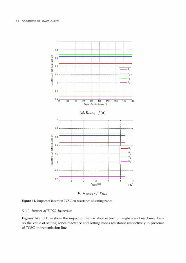
Figure 13. Impact of insertion TCSC on resistance of setting zones
5.3.3. Impact of TCSR Insertion
Figures 14 and 15 is show the impact of the variation extinction angle α and reactance XTCSR on the value of setting zones reactance and setting zones resistance respectively in presence of TCSC on transmission line.

Impact of Series FACTS Devices (GCSC, TCSC and TCSR) on Distance Protection Setting Zones in 400 kV Transmission Line 57
Figure 14. Impact of insertion TCSR on reactance of setting zones

An Update on Power Quality 58
Figure 15. Impact of insertion TCSR on resistance of setting zones
6. Conclusions
The results are presented in relation to a typical 400 kV transmission system employing GCSC, TCSC and TCSR series FACTS devices. The effects of the extinction angle γ for controlled GTO installed on GCSC as well as extinction angle α for controlled thyristors on TCSC and TCSR are investigated. These devices are connected at the midpoint of a transmission line protected by distance relay. However as demonstrated these angles injected variable reactance (XGCSC, XTCSC or XTCSR) in the protected line which lead to direct impact on the total impedance of the protected line and setting zones.

Impact of Series FACTS Devices (GCSC, TCSC and TCSR) on Distance Protection Setting Zones in 400 kV Transmission Line 59
Therefore settings zones of the total system protection must be adjusted in order to avoid unwanted circuit breaker tripping in the presence of series FACTS compensator.
Author details
Mohamed Zellagui and Abdelaziz Chaghi LSP-IE Research Laboratory, Department of Electrical Engineering, Faculty of Technology, University of Batna, Algeria
7. References
Acha, E.; Fuerte-Esquivel, C.R.; Ambriz-Pérez, H.; & Angeles-Camacho, C., (2004). FACTS Modelling and Simulation in Power Networks, John Wiley & Sons Ltd Publication, ISBN: 978-0470852712, London, England.
Blackburn, J.L.; Domin, T.J. (2006). Protective Relaying: Principles and Applications, 3rd Edition, Published by CRC Press, ISBN: 978-1574447163, USA.
De Jesus F. D.; De Souza L. F. W.; Wantanabe E.; Alves J. E. R. (2007). SSR and Power Oscillation Damping using Gate-Controlled Series Capacitors (GCSC), IEEE Transaction on Power Delivery, Vol. 22, N°3, (Mars 2007), pp. 1806-1812.
De Souza, L. F. W.; Wantanabe, E. H.; Alves, J. E. R. (2008). Thyristor and Gate-Controlled Series Capacitors: A Comparison of Component Ratings, IEEE Transaction on Power Delivery, Vol. 23, No.2, (May 2008), pp. 899-906.
Dechphung, S.; Saengsuwan, T. (2008). Adaptive Characteristic of MHO Distance Relay for Compensation of the Phase to Phase Fault Resistance, IEEE International Conference on Sustainable Energy Technologies (ICSET’ 2008), Singapore, Thailand, 24-27 November 2008.
Gérin-Lajoie, L. (2009), A MHO Distance Relay Device in EMTP Works, Electric Power Systems Research, 79(3), March 2009, pp. 484-49.
Horowitz, S.H.; Phadke A.G. (2008). Power System Relaying, 3rd Edition, Published by John Wiley & Sons Ltd, ISBN: 978-0470057124, England, UK.
Jamali, S.; Shateri, H. (2011). Impedance based Fault Location Method for Single Phase to Earth Faults in Transmission Systems, 10th IET International Conference on Developments in Power System Protection (DPSP), United Kingdom, 29 March - 1 April, 2010.
Kazemi, A.; Jamali, S.; Shateri, H. (2009). Measured Impedance by Distance Relay with Positive Sequence Voltage Memory in Presence of TCSC, IEEE/PES Power Systems Conference and Exposition (PSCE’ 09), Seattle, USA, 15-18 March 2009.
Khederzadeh, M.; Sidhu, T. S. (2006). Impact of TCSC on the Protection of Transmission Lines, IEEE Transactions on Power Delivery, Vol. 21, No. 1, (January 2006), pp. 80-87.
Kulkami, P. A.; Holmukhe, R. M.; Deshpande, K. D.; Chaudhari, P. S. (2010). Impact of TCSC on Protection of Transmission Line, International Conference on Energy Optimization and Control (ICEOC’ 10), Maharashtra, India, 28-30 December 2010.

An Update on Power Quality 60
Liu, Q.; Wang, Z. (2008). Research on the Influence of TCSC to EHV Transmission Line Protection, International Conference on Deregulation and Restructuring and Power Technology (DRPT’ 08), Nanjing, China, 6-9 April 2008.
Mathur, R.M.; Basati, R.S., (2002). Thyristor-Based FACTS Controllers for Electrical Transmission Systems, Published by Wiley and IEEE Press Series in Power Engineering, ISBN: 978-0471206439, New Jersey, USA.
McLaren, P. G.; Mustaphi, K.; Benmouyal, G.; Chano, S.; Girgis, A.; Henville, C.; Kezunovic, M.; Kojovic, L.; Marttila, R.; Meisinger, M.; Michel, G.; Sachdev, M. S.; Skendzic, V.; Sidhu, T. S.; Tziouvaras, D., (2001). Software Models for Relays, IEEE Transactions on Power Delivery, Vol. 16, No. 12, (April 2001), pp. 238-45.
Ray, S.; Venayagamoorthy, G. K.; Watanabe, E. H. (2008). A Computational Approach to Optimal Damping Controller Design for a GCSC, IEEE Transaction on Power Delivery, Vol. 23, No.3, (July 2008), pp. 1673-1681.
Sen, K.K.; Sen, M.L., (2009). Introduction to FACTS Controllers: Theory, Modeling and Applications", Published by John Wiley & Sons, Inc., and IEEE Press, ISBN: 978-0470478752, New Jersey, USA.
Sonelgaz Group/GRTE, (2011). Topologies of Electrical Networks High Voltage 400 kV, Technical rapport published by Algerian Company of Electrical Transmission Network, 30 December 2011, Sétif, Algeria.
Zellagui, M.; Chaghi, A. (2012.a). Distance Protection for Electrical Transmission Line: Equipments, Settings Zones and Tele-Protection, published by LAP Lambert Academic Publishing, ISSN: 978-3-659-15790-5, Saarbrücken - Germany.
Zellagui, M.; Chaghi, A. (2012.b). Measured Impedance by MHO Distance Protection for Phase to Earth Fault in Presence GCSC, ACTA Technica Corviniensis : Bulletin of Engineering, Tome 5, Fascicule 3, (July-September 2012), pp. 81-86.
Zellagui, M.; Chaghi, A. (2012.c). A Comparative Study of FSC and GCSC Impact on MHO Distance Relay Setting in 400 kV Algeria Transmission Line, Journal ACTA Electrotehnica, Vol. 53, No. 2, (July 2012), pp. 134-143.
Zhang, X.P.; Rehtanz, C.; Pal, B., (2006). Flexible AC Transmission Systems: Modelling and Control, Springer Publishers, ISBN: 978-3642067860, Heidelberg, Germany.
Zigler, G. (2008). Numerical Distance Protection: Principles and Applications, 3rd Edition, Publics Corporate Publishing, Wiley-VCH, ISBN: 978-3895783180, Berlin, Germany.