implementation of sub-carrier modulation techniques … · modulation and demodulation of all the 3...
TRANSCRIPT
International Research Journal of Engineering and Technology (IRJET) e-ISSN: 2395 -0056
Volume: 03 Issue: 05 | May-2016 www.irjet.net p-ISSN: 2395-0072
© 2016, IRJET | Impact Factor value: 4.45 | ISO 9001:2008 Certified Journal | Page 3230
Implementation of Sub-Carrier Modulation Techniques Using
MATLAB/Simulink
1Ajay Kumar D, 2Parameshappa G , 3Savitha A C, 1PG student, Dept. of E&CE, JSSATEB, Karnataka, India
2Assistant Professor, Dept. of E&CE, JSSATEB, Karnataka, India 3Assistant Professor, Dept. of E&CE, JSSATEB, Karnataka, India
---------------------------------------------------------------------***--------------------------------------------------------------------
Abstract: This paper aims at designing a Telecommand modem used in satellites which can modulate and demodulate low data rate signals using high frequency carriers. The main application of this type of MODEM is in satellite Telecommand systems. To transmit low data rate command signals, 2-level modulation technique called sub-carrier modulation is used. We use 3 different sub-carrier modulations techniques in this paper; they are PSK/PM, FSK/FM and PSK/FM. 2-level modulation technique is used because at the end of second modulation the message signal will be sufficiently away from the phase noise of the carrier which gets introduced because of the modulation of low data rate signal with high frequency carrier and can be recovered easily at the receiver side ([1], [2], [3], [4]). Modulation and demodulation of all the 3 sub-carrier modulation techniques are done. Simulation tool used is MATLAB/Simulink.
Keywords: Phase shift keying (PSK), Frequency shift keying (FSK), Frequency modulation (FM), Phase modulation (PM), Phase-locked loop (PLL).
1. INTRODUCTION:
A Satellite is a natural or man-made body gyrating around a celestial body. A satellite is launched to perform designated functions like exploring other planets, Television broadcast, Communication, Weather forecast, Surveying, Finding natural resources, Military purpose etc. Satellite ground stations are the centres from where the orders are sent to and receive the responses from satellite. The commands to be sent to the satellite will be in the form of digital data and they are often referred as baseband data. The data to be sent should traverse a long distance to reach the satellite and also it should reach satellite in the same format without losing integrity. There are chances that the data sent may not reach the satellite or reach the satellite but in different format due to noise. In this paper we deal with this portion of commanding the satellite where we need to make sure the command sent to the satellite is correctly received by the satellite.
The satellite has 2 external interfaces they are Telecommand and Telemetry. The processing of uplink and downlink is called Telecommand and Telemetry
respectively. The Telecommands are the commands sent to the satellite from ground station. Telecommands determine the behaviour if the satellite. On board satellite Telecommand is received, decoded and distributed to the computers to control or change the operational status of the satellite. The telemetry data are sent to ground station from satellite. Telemetry data is divided into 2 categories: payload telemetry and housekeeping telemetry. The payload telemetry provides the information collected by satellite. The housekeeping telemetry provides information about the status of the satellite. On board satellite telemetry data is acquired, encoded and transmitted to ground station. This is used by ground station to control and also to look after the performance of all on-board subsystems of the satellite.
Telecommanding is carried out not only to maintain the satellite in its orbit but for other purposes also. Commands are sent to the Satellite by modulating them in the Ground Station and they are demodulated “onboard” the Satellite. This paper involves the Modulation and Demodulation Sections of Telecommand Link. There are many different techniques for modulating the data to be sent to the satellite. Technique Selection for modulating the data depends on various parameters such as power requirement, Bandwidth requirement, Bit-error rate performance (BER) etc.
This paper aims at designing a Telecommand modem used in satellites which can modulate and demodulate low data rate signals using high frequency carriers. A command signal that is digital data, to be sent is of very low rate - 100 bps. But the carrier used to send the command to satellite will be in S-band (Range is 2-4GHz). The problem arises here, as the command signal is of very low data rate and carrier is of very high frequency, the modulation of these two overlaps the command signal in the phase noise of the carrier generator. Since C/N will be low at the receiver it will be impossible to demodulate the command signal. Solution to this problem is by 2- level modulation approach called sub-carrier modulation, so that at the end of second modulation the message signal will be sufficiently away from the phase noise of the carrier generator and can be easily demodulated and recovered in the receiver.

International Research Journal of Engineering and Technology (IRJET) e-ISSN: 2395 -0056
Volume: 03 Issue: 05 | May-2016 www.irjet.net p-ISSN: 2395-0072
© 2016, IRJET | Impact Factor value: 4.45 | ISO 9001:2008 Certified Journal | Page 3231
Low data rate command signal can be transmitted on S-band by using 2-level modulation schemes like PSK/PM, FSK/FM and PSK/FM. The first level of modulation is digital modulation that is PSK or FSK Modulation. The final modulation is analog modulation done on IF carrier of relatively low frequency (10 to 70 MHz). Then the modulated signal can be up converted to S-band and amplified for transmission. In this Paper PSK/PM, FSK/FM and PSK/FM Modulation and Demodulation are carried out. The PSK/PM, FSK/FM and PSK/FM system is simulated using MATLAB/Simulink environment. RF up conversion and down conversion modules are not addressed in this paper ([1], [2], [3], [4]).
2. OVERVIEW:
This paper aims at designing a Telecommand modem used in satellites which can modulate and demodulate low data rate signals using high frequency carriers. A command signal that is digital data, to be sent is of very low rate - 100 bps. But the carrier used to send the command to satellite will be in S-band (Range is 2-4GHz). The problem arises here; Local Oscillators (LO) used for generation of the carrier signal contain spurious side bands. Due to the phase noise associated with the oscillator, the spurious side bands are formed around the carrier. As the command signal is of very low data rate and carrier is of very high frequency, the modulation of these two overlaps the command signal in the phase noise of the carrier generator. Since C/N will be low at the receiver it will be impossible to demodulate the command signal.
Solution to this problem is by two level modulation approach called sub-carrier modulation, so that at the end of second modulation the message signal will be sufficiently away from the phase noise of the carrier generator and can be easily demodulated and recovered in the receiver. RF up conversion and down conversion modules are not addressed in this paper ([1], [2], [3], [4]).
Fig -1: Ground station
Fig -2: Onboard Satellite
3. PLL AS DEMODULATOR:
The loop is said to be locked, if the control voltage is such that the frequency of VCO is exactly equal to the frequency of the input. To maintain control voltage required for loop lock it is necessary to have a non-zero output from phase detector. The loop operates with some phase error; in practical scenario this tends to be small if the loop is well designed.
If the input signal carries information in its phase or frequency, then inevitably this signal is corrupted by additive white noise. PLL replicate the original signal removing as much of the noise as possible. To replicate the original signal PLL makes use of local oscillator, whose frequency is nearly close to the expected signal. Local oscillator signal and input signals are compared by phase detector. The error is averaged over some finite length of time to suppress the noise and this average value of error is used to establish the frequency of oscillator.
If the input signal is stable in frequency, then the of time local oscillator may need very little information to track and the information can be obtained by averaging for long period, thereby eliminating large noise. The input to the loop is noisy signal and the output of the VCO is noise-free version of input. The features such as narrow band width requirement for loop filter, which is capable of rejecting noise and automatic tracking makes the PLL best receivers or demodulators or detectors [10].
Fig -3: Phase locked loop (PLL)
4. IMPLEMENTATION IN MATLAB/SIMULINK
In this section design and implementation various blocks involved in PSK/PM, FSK/FM, PSK/FM modem is discussed ([5], [6], [7], [8], [9])..
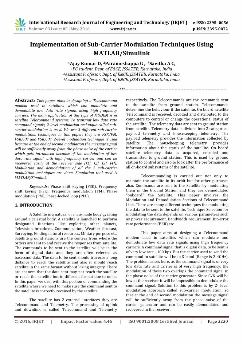
A) PSK/PM modem: Here the first level of modulation used is PSK and second level is PM.
1) PSK Modulation: When the phase of the carrier wave is altered with reference of the modulating signal then the resultant modulation scheme is termed as Phase Shift Keying. 𝑆 𝑡
= V𝑐 cos 2πf𝑐t − symbol′0′
V𝑐 cos 2πf𝑐t + π − symbol′1′
International Research Journal of Engineering and Technology (IRJET) e-ISSN: 2395 -0056
Volume: 03 Issue: 05 | May-2016 www.irjet.net p-ISSN: 2395-0072
© 2016, IRJET | Impact Factor value: 4.45 | ISO 9001:2008 Certified Journal | Page 3232
Fig -4: PSK modulator
2) PM Modulator: Phase modulation (PM) is that
form of angle modulation in which the instantaneous angle θi(t) is varied linearly with the message signal as shown by Fig 5.
θi(t)= 2π fct+kpm(t)
Fig -5: PM modulator
3) PM Demodulator: PM demodulation is done using PLL as shown in Fig 6.
Fig -6: PM Demodulator using PLL
4) PSK Demodulator: PSK demodulation is done using costas loop as shown in Fig 7.
Fig -7: PSK Demodulation using Costas loop
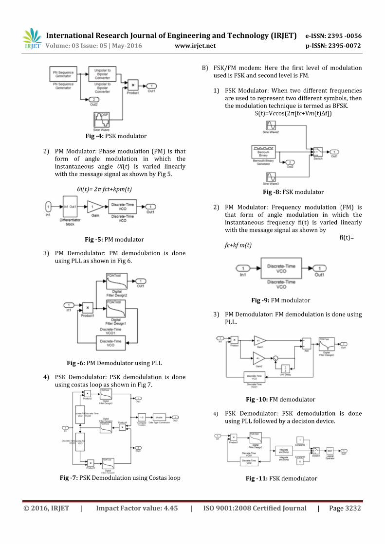
B) FSK/FM modem: Here the first level of modulation used is FSK and second level is FM. 1) FSK Modulator: When two different frequencies
are used to represent two different symbols, then the modulation technique is termed as BFSK.
S(t)=Vccos(2π[fc+Vm(t)∆f])
Fig -8: FSK modulator
2) FM Modulator: Frequency modulation (FM) is
that form of angle modulation in which the instantaneous frequency fi(t) is varied linearly with the message signal as shown by fi(t)= fc+kf m(t)
Fig -9: FM modulator
3) FM Demodulator: FM demodulation is done using PLL.
Fig -10: FM demodulator
4) FSK Demodulator: FSK demodulation is done using PLL followed by a decision device.
Fig -11: FSK demodulator

International Research Journal of Engineering and Technology (IRJET) e-ISSN: 2395 -0056
Volume: 03 Issue: 05 | May-2016 www.irjet.net p-ISSN: 2395-0072
© 2016, IRJET | Impact Factor value: 4.45 | ISO 9001:2008 Certified Journal | Page 3233
C) PSK/FM modem: Here the first level of modulation used is PSK and second level is FM.
1) PSK Modulation: When the phase of the carrier wave is altered with reference of the modulating signal then the resultant modulation scheme is termed as Phase Shift Keying. 𝑆 𝑡 =
V𝑐 cos 2πf𝑐t − symbol′0′
V𝑐 cos 2πf𝑐t + π − symbol′1′
Fig -13: FM modulator
2) FM Modulator: Frequency modulation (FM) is
that form of angle modulation in which the instantaneous frequency fi(t) is varied linearly with the message signal as shown by fi(t)= fc+kf m(t)
Fig -12: PSK modulator
3) FM Demodulator: FM demodulation is done using PLL.
Fig -15: PSK demodulator
4) PSK Demodulator: PSK demodulation is done using costas loop as shown below.
Fig -14: FM demodulator
D) Clock Recovery:
The receiver must determine the start and end of each symbol. Symbol synchronization also referred to as clock recovery, is important for correct detection of symbols. The clock recovered acts as reference for the data and can also be used for further processing like decoding, etc. Clock recovery can be done using PLL.
Fig -16: clock recovery using PLL
1) Top module of PSK/PM:
Fig -17: PSK/PM modem
2) Top module of FSK/FM:
Fig -18: FSK/FM modem
3) Top module of PSK/FM:
Fig -19: PSK/FM modem

International Research Journal of Engineering and Technology (IRJET) e-ISSN: 2395 -0056
Volume: 03 Issue: 05 | May-2016 www.irjet.net p-ISSN: 2395-0072
© 2016, IRJET | Impact Factor value: 4.45 | ISO 9001:2008 Certified Journal | Page 3234
5. SIMULATION RESULTS
Frequency specifications for simulations used in this paper.
Table -1: PN sequence specifications
TYPE FREQUENCY DECSRIPTION Random Binary Pulse
100bps This is the random data to be transmitted.
Table -2: Carrier frequency specifications
Subcarrier Sine wave
Carrier Sine wave
Carrier Signals (PSK/PM)
1000Hz 20,000Hz
Carrier Signals (FSK/FM)
fm1=3000Hz and fm2=5000Hz
20,000Hz
Carrier Signals (PSK/FM)
1000Hz 20,000Hz
Fig -20: simulation results of PSK/PM
Fig -21: simulation results of FSK/FM
Fig -22: simulation results of PSK/FM
6. CONCLUSION AND FUTURE WORK
Two level modulations namely PSK/PM, FSK/FM and PSK/FM are considered for transmitting the low bit rate command data on S-band carrier in the frequency band allotted by ITU for satellite uplinks. PSK/PM, FSK/FM and PSK/FM modulator and demodulator are designed, simulated with Simulink tool of Matlab. The simulation results are presented.
Future work can be
1) Baseband system formatting can be done like encoding and decoding, encryption, decryption, up conversion and down conversion.
2) Advanced satellites require high data rates around 1Kbps for Telecommanding. The Modem can be designed with high data rates.
3) Channel considered in this paper is noise free channel. AWGN noise channel can be taken and BER analysis can be done.
ACKNOWLEDGMENTS
The authors would like to express their sincere thanks to Dr. Mrityunjaya V.Latte, Principal, JSSATEB, Dr. Aravind H.S., HOD, Dept. of ECE, JSSATEB and Dr.Siddesh.G.K., PG Co-ordinator, Dept. of ECE, JSSATEB for the encouragement given throughout this development work.
REFERENCES
[1] Jagadevi PatiI, P S Anuradha, K V Maruthi Prasad, W V Eswara Prakash, “Event Based Commanding” 0-7803-7651 -X/03/©2003 IEEE.
[2] Ondrej Baran, Miroslav Kasal, Tomas Urbanec, Petr Vagner, “Phase Noise Effects on Satellite Low-Rate Data Signals” 978-1-4673-6396-9/13/©2013 IEEE.
[3] Qiuting Huang, Senior Member, IEEE “Phase Noise to Carrier Ratio in LC Oscillators” IEEE Transactions on

International Research Journal of Engineering and Technology (IRJET) e-ISSN: 2395 -0056
Volume: 03 Issue: 05 | May-2016 www.irjet.net p-ISSN: 2395-0072
© 2016, IRJET | Impact Factor value: 4.45 | ISO 9001:2008 Certified Journal | Page 3235
Circuits and Systems—I: Fundamental Theory and Applications, Vol. 47, No. 7, July 2000.
[4] Ondrej Baran, Miroslav Kasal, Petr Vagner and Tomas Urbanec, “Phase Noise Impact on BER in Space Communication” International Journal of Electrical, Computer, Energetic, Electronic and Communication Engineering Vol: 6, No: 9, 2012.
[5] You Zheng and Carlos E. Saavedra, “A BPSK Demodulator Circuit using an Anti-Parallel Synchronization Loop” 0-7803-8834-8/05/ ©2005 IEEE.
[6] LaiGong Guo, MingSan OuYang, Jun Cai, “Simulation and Implementation of Costas” 978-1-4244-8039-5/11/ ©2011 IEEE.
[7] Wu ChangFu, “Analysis, Design and Implementation of FSK Modulate Systems” Proceedings of the 2nd International Conference On Systems Engineering and Modeling (ICSEM-13).
[8] Dr. Apren T J, Sona Sunny, Jaison Varghese John, “Quadrature detection methods for FM Demodulation” Third International Conference on Advances in Computing and Communications , 978-0-7695-5033-6/13 © 2013 IEEE.
[9] D. Leόn, S. Balkır, M.W. Hoffman and L.C. Pérez, “Pseudo-chaotic PN-sequence generator circuits for spread spectrum communications” IEEE Proc.-Circuits Devices Syst., Vol. 151, No. 6, December 2004. [10] Martin Kumm, Harald Klingbeil, and Peter Zipf, “An FPGA-Based Linear All-Digital Phase-Locked Loop” IEEE Transactions On Circuits And Systems—I: Regular Papers, September 2009.