implementation of the dams complex of upper atbara, … · implementation of the dam complex at...
TRANSCRIPT

Implementation of the Dam Complex at Upper Atbara,
Sudan, in challenging site conditions
Frank Zoellner Yannick Scheid Musab Mukthar
Lahmeyer International GmbH Lahmeyer International GmbH Dams Implementation Unit
Friedberger Straße 133 Friedberger Straße 133 Ministry of Electricity and Dams
61118 Bad Vilbel 61118 Bad Vilbel Abdullah Elnoor Street 5, Khartoum
Germany Germany Sudan
Introduction
The reservoir of the Dam Complex of Upper Atbara Multipurpose Project DCUAP impounds the Upper Atbara and
the Setit River approximately 20 km south and upstream of their confluence, located in the Gedaref Governorate in
East of Sudan. DCUAP is set up for irrigation of more than 300,000 ha, power generation of 320 MW, flood control
and water supply for around 450,000 consumers by a pipeline executed within the frame of the connected Gedaref
Water Supply Project GWSP.
The plant is owned by the Dams Implementation Unit DIU under the Ministry of Electricity and Dams. The civil
works are executed by the Joint Venture of China International Water & Electric Corp. CWE and China Three
Gorges Corporation CTGC. The works related to the supply of Gedaref by 75,000 m³ of water per day purified
according to WHO-Standards are executed within the scope of a separate EPC-Turnkey-Contract of a 55 Mio. USD
volume awarded to CWE. The electromechanical works are implemented by Harbin Electric International Company
HEI, China. The total costs for DCUAP are approximately 1.1 Billion USD, financed mainly by Arabic
Development Banks. The construction works of DCUAP started in the year 2010, and the first reservoir impounding
has been completed by end of 2016. Two of four Powerhouse Units are commissioned by first half of 2017. The first
kilometers of the GWSP water pipeline have been embedded at this time as well.
The Consultancy Services by Lahmeyer International GmbH LI, Germany, related to DCUAP are mainly comprising
the review of the previous design and tender documents, provision of support during the tendering phase, and the
construction supervision. For GWSP, the tasks of LI included the design review of the Contractor’s EPC-Design, the
contract administration and the site supervision, whereas the review of the design of the technical equipment was
carried out to large extent by the LI-subsidiary GKW Consult GmbH. The Consulting Engineers of LI have been
working in the Sudan continuously for around 40 years in the fields of planning, designing and supervising
construction of electric power plants and their distribution systems.
Multipurpose-Projects as DCUAP are of highest importance for Sudan. A continuous water supply throughout the
whole year is the key for further developing the high potential of the agricultural economy favored by fertile soils,
high level of irradiation and warm temperatures. At the same time, an increase and decentralization of the national
electrical capacity is needed in order to develop further industrialization and improve the living conditions.
Currently, the 1,250 MW Merowe HPP located at the Nile supplies around 50% of the country’s electrical energy.
Challenges experienced during implementation of the Projects DCUAP and GWSP are mainly related to the local
climate conditions and the associated extraordinary flood regimes of the rivers, as well as to the particular bedrock
conditions. Further, the remote location resulted in long shipping times of the construction materials and equipment
as imported from overseas by the Chinese Contractors. The thin local infrastructure required comprehensive site
preparation and installations. While most of these challenges had to be mastered during times of construction, the
flood regime and sediment loads of the rivers will have to be controlled during the whole operation time of the plant.
1. The Main Characteristics of the Dam Complex of Upper Atbara
The interconnected DCUAP dams of the “Rumela” System on the Upper Atbara River and the “Burdana” System on
the Setit River have a total length of about 13 km and a dam crest elevation of 525 masl. Both dams consist of a
zoned earth fill embankment dam at the river sections with maximum heights of around 50 m, and a system of zoned
and homogeneous embankment dams with maximum 25 m of height. The total fill volume for the embankments is
11.9 million m³. A volume of nearly exactly the same amount was excavated. The impoundment with a maximum
gross head of 41.4 m is created by a total storage volume of 3.7 billion m³ (active 2.5 billion m³). Reinforced
spillway structures with 950,000 m³ concrete in total have been built to enable maximum discharge of 6,150 m³/s
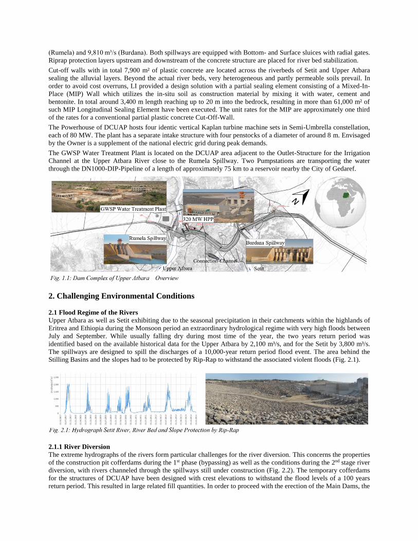
(Rumela) and 9,810 m³/s (Burdana). Both spillways are equipped with Bottom- and Surface sluices with radial gates.
Riprap protection layers upstream and downstream of the concrete structure are placed for river bed stabilization.
Cut-off walls with in total 7,900 m² of plastic concrete are located across the riverbeds of Setit and Upper Atbara
sealing the alluvial layers. Beyond the actual river beds, very heterogeneous and partly permeable soils prevail. In
order to avoid cost overruns, LI provided a design solution with a partial sealing element consisting of a Mixed-In-
Place (MIP) Wall which utilizes the in-situ soil as construction material by mixing it with water, cement and
bentonite. In total around 3,400 m length reaching up to 20 m into the bedrock, resulting in more than 61,000 m² of
such MIP Longitudinal Sealing Element have been executed. The unit rates for the MIP are approximately one third
of the rates for a conventional partial plastic concrete Cut-Off-Wall.
The Powerhouse of DCUAP hosts four identic vertical Kaplan turbine machine sets in Semi-Umbrella constellation,
each of 80 MW. The plant has a separate intake structure with four penstocks of a diameter of around 8 m. Envisaged
by the Owner is a supplement of the national electric grid during peak demands.
The GWSP Water Treatment Plant is located on the DCUAP area adjacent to the Outlet-Structure for the Irrigation
Channel at the Upper Atbara River close to the Rumela Spillway. Two Pumpstations are transporting the water
through the DN1000-DIP-Pipeline of a length of approximately 75 km to a reservoir nearby the City of Gedaref.
2. Challenging Environmental Conditions
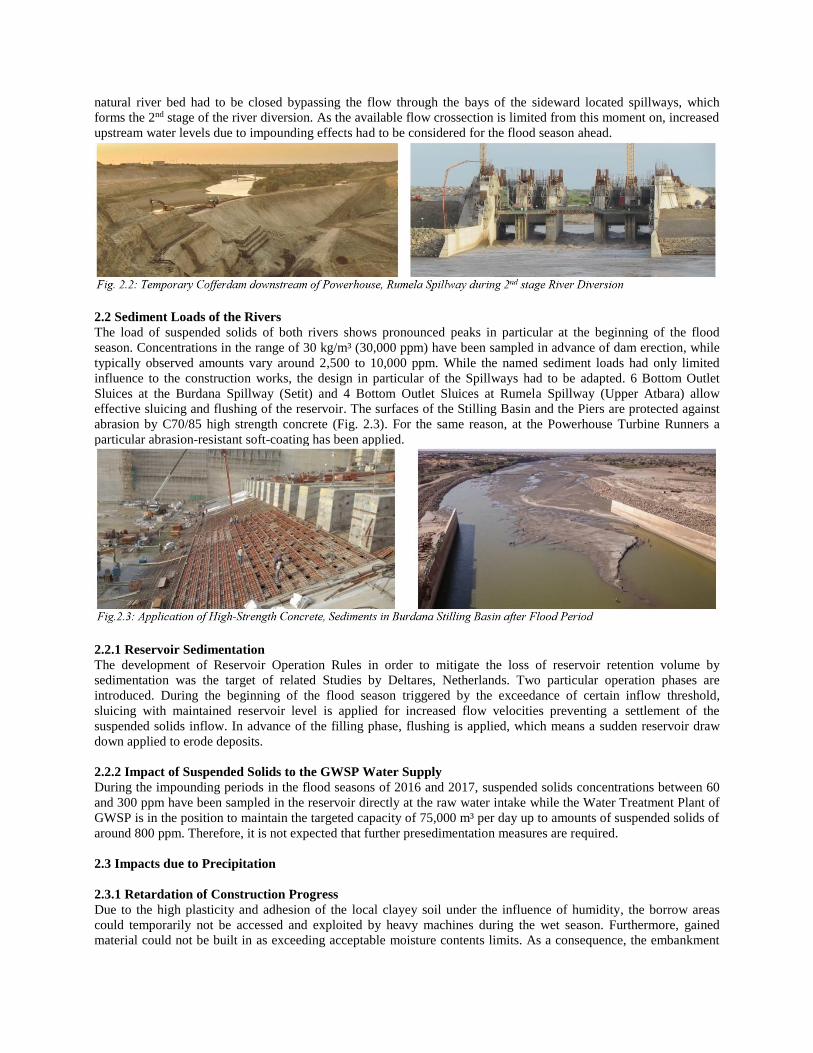
2.1 Flood Regime of the Rivers
Upper Atbara as well as Setit exhibiting due to the seasonal precipitation in their catchments within the highlands of
Eritrea and Ethiopia during the Monsoon period an extraordinary hydrological regime with very high floods between
July and September. While usually falling dry during most time of the year, the two years return period was
identified based on the available historical data for the Upper Atbara by 2,100 m³/s, and for the Setit by 3,800 m³/s.
The spillways are designed to spill the discharges of a 10,000-year return period flood event. The area behind the
Stilling Basins and the slopes had to be protected by Rip-Rap to withstand the associated violent floods (Fig. 2.1).
2.1.1 River Diversion
The extreme hydrographs of the rivers form particular challenges for the river diversion. This concerns the properties
of the construction pit cofferdams during the 1st phase (bypassing) as well as the conditions during the 2nd stage river
diversion, with rivers channeled through the spillways still under construction (Fig. 2.2). The temporary cofferdams
for the structures of DCUAP have been designed with crest elevations to withstand the flood levels of a 100 years
return period. This resulted in large related fill quantities. In order to proceed with the erection of the Main Dams, the
natural river bed had to be closed bypassing the flow through the bays of the sideward located spillways, which
forms the 2nd stage of the river diversion. As the available flow crossection is limited from this moment on, increased
upstream water levels due to impounding effects had to be considered for the flood season ahead.
2.2 Sediment Loads of the Rivers
The load of suspended solids of both rivers shows pronounced peaks in particular at the beginning of the flood
season. Concentrations in the range of 30 kg/m³ (30,000 ppm) have been sampled in advance of dam erection, while
typically observed amounts vary around 2,500 to 10,000 ppm. While the named sediment loads had only limited
influence to the construction works, the design in particular of the Spillways had to be adapted. 6 Bottom Outlet
Sluices at the Burdana Spillway (Setit) and 4 Bottom Outlet Sluices at Rumela Spillway (Upper Atbara) allow
effective sluicing and flushing of the reservoir. The surfaces of the Stilling Basin and the Piers are protected against
abrasion by C70/85 high strength concrete (Fig. 2.3). For the same reason, at the Powerhouse Turbine Runners a
particular abrasion-resistant soft-coating has been applied.
2.2.1 Reservoir Sedimentation
The development of Reservoir Operation Rules in order to mitigate the loss of reservoir retention volume by
sedimentation was the target of related Studies by Deltares, Netherlands. Two particular operation phases are
introduced. During the beginning of the flood season triggered by the exceedance of certain inflow threshold,
sluicing with maintained reservoir level is applied for increased flow velocities preventing a settlement of the
suspended solids inflow. In advance of the filling phase, flushing is applied, which means a sudden reservoir draw
down applied to erode deposits.
2.2.2 Impact of Suspended Solids to the GWSP Water Supply
During the impounding periods in the flood seasons of 2016 and 2017, suspended solids concentrations between 60
and 300 ppm have been sampled in the reservoir directly at the raw water intake while the Water Treatment Plant of
GWSP is in the position to maintain the targeted capacity of 75,000 m³ per day up to amounts of suspended solids of
around 800 ppm. Therefore, it is not expected that further presedimentation measures are required.
2.3 Impacts due to Precipitation
2.3.1 Retardation of Construction Progress
Due to the high plasticity and adhesion of the local clayey soil under the influence of humidity, the borrow areas
could temporarily not be accessed and exploited by heavy machines during the wet season. Furthermore, gained
material could not be built in as exceeding acceptable moisture contents limits. As a consequence, the embankment

fill rates during the rainy season have been affected. While during the dry season typical total filling rates between
300,000 and 1,000,000 m³ per month could be achieved, with around 40,000 m³/month only around 10% could be
attained during the rain periods of usual precipitation rates (Fig. 2.4).
In contrast, the DCUAP concreting rates with peak volumes of 45,000 m³ per month were not seriously affected
during the rainy seasons.
The prevailing Vertisol of the southern Butana Clay Plain forms a morass during times of the rainy season which
prevents frequently entering with heavy machines for trench excavation and pipeline placing. The pipeline execution
works for GWSP had therefore to be suspended. Flexible connections of the individual DIP pipes ensure axial
adaptability of the pipeline required due to the pronounced moisture-related swelling of the “Black Cotton Soil”.
2.3.2 Rainstorm Damages
The local yearly average rainfall rate is reported by around 690 mm. For July and August, the rates vary around 170
to 190 mm. However, typically these amounts are not adding up within prolonged steady rain, but during individual
events of partially extremely heavy rainstorms within a few hours. The local Extreme Precipitation Index is close to
200 mm / 24 hrs. Normally dry Wadis turn into torrential rivers during such occurrences and led to erosion damages
also on the DCUAP site, with the permanent dewatering systems not having been implemented yet (Fig. 2.5).
2.3.3 High Ambient Temperatures
The chart of local average ambient temperatures shows two peaks in May and November. Maximum air temperatures
of around 42 - 44 °C are frequently experienced. These high temperatures mainly have to be considered for the
concreting works in order to limit concrete core temperatures during hydration. Mass concrete was therefore cooled
down to 22 °C. No thermally caused concrete cracks were observed in the block units of up to 3500 m³, which might
be supported by low temperature differences between the hydration-heated core and the environment.
2.3 Local Infrastructure
With the closest river transverse for heavy vehicles formed by the Kashm El Girba Dam 80 km downstream, the
construction of bridges crossing Upper Atbara and Setit was needed before the actual construction works could start.
The non-availability of electric grid connections close to the location of DCUAP Site made necessary the installation

of two temporary Diesel power plants of each around 10 MW for electrical supply of the site installations and
equipment as cranes. Water purification plants and two clinics have been established for the staff of the site, with
during peak times around 3500 accommodated people. For the construction materials, as approximately 250,000 t of
cement and 60,000 t of reinforcement, shipping times of at least 2 months had to be considered as imported from
overseas requiring a “just-in-time” material management in particular for goods sensitive to heat or humidity.
3. Challenging Foundation Conditions
The rifting situation at the site resulted from a fracturing of the Nubian Sandstone package in a mainly SE-NW
running and is nearly perpendicular to the fault system. The joint and fault pattern is more or less vertical. This
pattern was determining the orientation of the actual main river beds and the main erosion gullies. After a long
period of erosion of the cretaceous sandstone the area was buried by the younger fluviatile and lacustrine sediments
as clay, silt, sand, gravel, cobbles (Karab material) transported from the Eritrean and Ethiopian Highlands into a huge
river delta and even paleo-lake environment.
The design for the embankment dams on soil foundation developed for the tender design was based on the
understanding that the foundation soils are accentuated and include soil layers to certain depths, but will be
sufficiently impervious to be keyed by core material of limited depths (~ 5 m) into the rock.
When Lahmeyer International inherited the project, the experts decided to run site investigations to confirm this
initial perception of the site conditions, which was mainly based on geophysical investigations.
At two locations of the project, the Fashaga section and the Burdana Right Bank section and for lengths of 1400 m
and 2000 m respectively, investigations including core drilling however revealed very complex foundation
conditions. The drilling demonstrated that the soil foundation is composed of clayey, silty, sandy and gravelly
alluvial and colluvial deposits to greater depth. In top levels the clays, silts and fine sands dominate the foundation,
while medium to coarse poorly graded sands as well as gravelly layers govern the lower sections. In Sudan, these
soils are typically referred to as Karab formation (Fig. 3.1). Such layers reached into depths of 20 - 30 m under the
foundation of the dam.
At the start and end points in Fashaga, the dam can be founded on the Nubian Sandstone formation. In the central
part of Fashaga the site investigations identified a deep pervious zone with a length of approximately 1,600 m, which
led to the hypothesis of a paleontological channel in the foundations filled with pervious materials, but fines as well.
The depth of the ancient valley is about 70 m below ground level in deeper sections.
The paleontological channel, if crossing the dam axis may trigger additional flow from upstream to downstream. A
final conclusion on its existence could not be confirmed until today.
The horizontal deposition of more and less permeable soil layers causes anisotropic flow conditions under the dam
foundations. However, the continuity and the sequence of the layers did not present any defined pattern. It was
understood that such formation may present locally high permeabilities and could result in increased seepage and
critical hydraulic gradients at the downstream toe of the dam.
The overall coefficient of permeability could be determined with 10-4 m/s to 10-6 m/s in the pervious formation. This
could be demonstrated by grain size distribution analyses from foundation samples as well as from pumping tests.
Gravelly banks are likely to have permeability coefficients up to 10-3 m/s.

The downstream toe of the embankment in Fashaga and on the Right Bank of the Setit is not plain and even, but
rather consists of deep cuts and Wadis in immediate vicinity of the toe. Wadis are connected to the Setit in the
section under consideration. Pervious sections are likely to emerge at the surface. The groundwater level is
connected to the river water levels.
3.1 The Mixed In Place Sealing Element
The results of the investigations made clear that the initial design with a keying of the dam core into the foundation
required important amendments including a barrier to cut flow in pervious formations. Lahmeyer initially
recommended a conventional two-phase cut-off wall, which would have been the appropriate choice at earlier design
stage. However, the contracts were already signed and such measure would have increased the costs of the project
significantly because of the total length of 3.4 km and the maximum depth of about 70 m into the foundation to reach
the rock foundation. It was estimated that a conventional cut-off wall would lead to additional costs of 100 Mio USD
corresponding to about 10% of the total project costs. This was not feasible, especially in a sensitive economy such
as the Sudan, and for an item that was not predicted by the responsible third Engineer during tender design. The
project partners Lahmeyer and DIU investigated on cost efficient and technically sound but innovative solutions to
overcome the challenging foundation situation.
3.1.1 Numerical modelling of measures to control seepage
So as to accommodate the complexity of the issue and eliminate all possible risks, parametric flow model analyses
were performed. Lahmeyer investigated on vertical seepage barrier solutions in combination with parameter
variations:
• Investigation of partial or full seepage barriers
• Partial seepage barriers with varying penetration depths
• Variation of the range of the soil permeability
• Flow under homogeneous and inhomogeneous isotropic and anisotropic geotechnical conditions
• Effect of a shallow impervious layer
A typical section of the embankment dam used for the model is shown in Figure 3.2.
Starting from the first and second parameter, the reference at the start was to construct a full vertical seepage barrier
that would bridge the clay core of the earth-fill dam with the underlying bedrock which was encountered at an
average depth of about 40 m and a maximum one of 70 m. It becomes obvious that for a stretch of 3400 m the
resources and time required would increase disproportionately. For that reason, different depths of the vertical barrier
were analyzed, starting from the case of no seepage wall and full seepage wall, so as to specify the analysis
boundaries, and then performing sensitivity runs for 10 m, 15 m and 20 m depths.

As the Karab formation is largely varying, three different permeability coefficients 10-4, 10-5 and 10-6 m/s were used,
which cover the range of coarse sand and gravel (10-4 m/s) to sandy clay/silt (10-6 m/s). For completeness, the
parameters for clay core of the dam are 10-8 m/s and for the seepage barrier 10-9 m/s respectively.
As mentioned before the Karab formation presented a horizontal layering of successive permeable and less
permeable layers. This characteristic imparts an anisotropic permeability to the material which was represented in the
analyses with the coefficient. For the purposes of the project, both isotropic permeability conditions kH/kV=1 and
anisotropic kH/kV=100 were investigated. The anisotropic permeability is more favorable due to the fact that it
obstructs the water flow in the vertical direction.
Taking the design into an even more detailed approach, it was observed in some of the investigation boreholes that
the higher foundations layers present a rather isotropic character (only sand for example) and the aforementioned
characteristic layering was starting at a depth. For that reason, additional sensitivity analyses were performed with
the combination of isotropic permeability and anisotropic permeability layers, with different permeability
coefficients, different interface elevation and different barrier depths.
Finally, the case of a shallow clay layer very close to the foundation level of the dam was investigated which could
result in excessive hydraulic gradients at the downstream toe.
This led to more than 300 finite element seepage analyses performed with the software Rocscience Slide®.
Obviously, the implementation of a seepage barrier is of significant importance for the stability and permeability of
the structure. The model demonstrated that without a seepage barrier the seepage may have reached uncontrollable
400 l/s per 100 m stretch or an unacceptable gradient at the downstream toe. These critical values were gradually
reduced as the seepage barrier was reaching deeper into the foundation layers. It was observed as well that it would
be beneficial if the vertical seepage barrier would penetrate the upper isotropic layers and cut into the lower
anisotropic sections with lower permeability. The model displayed that even if the seepage barrier penetrated only
one meter into the lower layers, the seepage would decrease by 40% compared to the model with no penetration.
With the above observations and further evaluation, the design was optimized to a 20 m deep seepage barrier, which
is the minimum depth to provide sufficient safety for all foundation conditions and permeability coefficients
considered.
3.1.2 The Mixed-in-Place Wall solution
Different solutions to build vertical seepage barrier walls were developed in foundation engineering. The regular cut-
off wall technology used for soil foundations in dam engineering replaces the soil by plastic concrete in two phases.
In the first phase, the soil is excavated and the trench is filled with a thick bentonite suspension, which is then
concreted from bottom to top with plastic concrete forming this way a non-structural but impermeable element into
the ground. This classical technology would have resulted in excessive costs for the long stretch on Karab formation.
Lahmeyer thus analyzed alternative solutions to provide large savings and proposed the Mixed-in-Place method. The
Mixed-in-Place method mixes the soil in place through the intrusion of flight augers that bond the geo-materials with
grout under high pressure. Lahmeyer proposed this method for the embankments located in the Karab formation of
the Upper Atbara Dam Project. The method provided with the following advantages:
• The Mixed-in-Place equipment can reach the required depths of 20 m into the foundation.
• The wall constructed with Mixed-in-Place technology can reach the required permeability coefficient of
10-9 m/s.
• With the Mixed-in-Place method radical cost savings are possible.
• It is a fast method with high advance rates.
• It is highly adaptable to the geotechnical conditions in soils.
• The Mixed-in-Place method utilizes the in-situ geomaterial as a building material, blending it with the
bonding agent into the structure of the wall. This significantly reduces the quantities of cement to be used.
The proposal comprised a novelty in the sealing of the foundation of a large hydropower project with a permanently
impounded reservoir. References to the application of this method are limited to dikes or cofferdams, where water
retaining is only temporarily.
The specialized contractor BAUER executed a 30-m test section so as to convince the Client and the Panel of
Experts about the suitability of the method. The section was excavated to observe the quality of the bonding and
provided very positive results (Fig. 3.3).

It was clear that the Mixed-in-Place wall could not be realized with the same control and accuracy as a conventional
approach of a two-phase Cut-off wall would guarantee. To convince all parties the teams developed a detailed
monitoring program as well as risk mitigation and preparedness plans for safe impounding and operation of the dam.
The first consists of magnetic settlement gauges, benchmarks, pore pressure cells, standpipe piezometers and seepage
measurement devices in relevant sections together with frequent site inspections. The risk mitigation included the
preparedness for installation of filter blankets with weighting berms (ballast), if required, and eventually the
construction of relief wells.
In total, 23 monitoring sections were distributed along the embankments. At critical locations seepage measuring
weirs were installed at the dam toes.
These measures were convincing to all parties and resulted in the decision to implement a new technology for the
permanent sealing of an embankment dam foundation – the Mixed-in-Place wall.
The 3.4 km long Mixed-in-Place wall was constructed in four months in 2013 - 2014 and the total costs were limited
to about 40 Mio USD. The cost savings to the Client were estimated in the range of 50 to 70 Mio USD or 5 to 7% of
the project value.
3.1.3 Observations and Measures
The impounding of the reservoir started in 2015. Typical daily impounding rates where between 10 and 20 cm.
Exemplarily, Figure 3.4 shows seepage measurement at the location with highest seepage. First seepage was
measured on 03 October 2015 at a reservoir level of 513.50 masl. The quantity was approximately 5 l/s. Since this
date the debit developed constantly to a rate of approximately 85 l/s. Based on the hydrogeological situation it may
be estimated that the measured water is originated from a dam portion with a length of 460 m. The figure identifies a
drop in seepage at the beginning of November 2015. This drop results from the improved measurement method by
weir measurement, rather than bucket measurement at the pipes that was previously applied. Figure 3.4 confirms that
the seepage rate is related to the reservoir water level, which is expected. While the seepage at most other locations
did not exceed the expected rates, higher seepage rates were measured at the upper boundary limit of the modelling
at the present location (up to 250 l/s). Some higher uplift pressures in the dam toe and the development of initial and
small piping holes (few centimeters in diameter) could be observed as well. At any time, seepage water remained
clear and the material transport was limited to a few cubic-centimeters at the sinkhole spots.
The team of the Engineer, Client and Contractor reacted rapidly and decided to place filters and ballast directly in the
dam toe trenches for a stretch of some 300 m.
With these measures implemented, no potentially critical developments were further observed at any location of the
embankments. The cost of the aforementioned countermeasures was negligible.

The Authors
Dr. Frank Zoellner, Civil Engineer, University of Stuttgart, Germany (2000). Following 6 years as research associate
at the chair of Hydraulic Engineering and Water Resources Management, Institute for Modelling Hydraulic and
Environmental Systems, University of Stuttgart (2000 - 2005). PhD at the same chair related to the application of
meshfree numerical methods in fields of hydraulic structures (2009). Dr. Frank Zoellner joins Lahmeyer
International for 10 years (since 2007). During this time, he was mainly in charge with the supervision of large hydro
projects. Currently, Dr. Frank Zoellner is acting as project manager at the Dam Complex of Upper Atbara, Sudan.
Dr. Yannick Scheid graduated in Civil and Geotechnical Engineering from Darmstadt University of Technology.
From 2000 to 2003 he was research assistant at Graz University of Technology, where he graduated with a Ph.D. In
2003, he joined Lahmeyer International and specialized in the field of dam engineering for hydro projects. During his
career, he gained scientific and professional experience in Sudan and more than 20 other countries as Dam Expert
and Project Manager. He was responsible for the embankment dam design of the DCUAP. Since 2016, Dr. Y. Scheid
is employed as manager in the Business Line Hydro of Tractebel Engineering.
Eng. Musab Mukhtar Mohamed holds the position as Deputy General Manager of the Dam Implementation Unit
(DIU), under the Ministry of Water Resources, Irrigation and Electricity, Sudan. At the same time, he acts as
Director General - Projects. Eng. Musab Mukhtar Mohamed accompanied the Dam Complex of Upper Atbara
Project by virtue of his office as Resident Engineer for Civil and Hydromechanical Works. The Dams
Implementation Unit under the Ministry of Water Resources, Irrigation and Electricity was established to develop
and utilize water resources across Sudan according to international measures and standards.
References
Rivas-Martínez, Salvador (2015), Worldwide Bioclimatic Classification System - Gedaref (Sudan), University
Complutense of Madrid, Spain
Mirghani, Muna (2001), Concepts and Models for the Characterization of the West Gedaref Hydrogeologic System,
Sudan, Sudan
Heynert, Yasir A. Mohamed et al (2016), Sedimentation and Operation Study for Atbara Dams Complex, Deltares,
Netherlands