implementation of the lists of characteristics of … of the lists of characteristics of namur...
TRANSCRIPT

Copyright 2005 by ISA - The Instrumentation, Systems and Automation Society.Presented at ISA 2005; http://www.isa.org
Reprinted by permission. All rights reserved.- 1 -
Implementation of the Lists of Characteristicsof NAMUR Recommendation NE 100
Dr. Peter Zgorzelski PMT – Intellectual Property ServicesBayer Technology Services GmbH51368 Leverkusen, Germany
KEYWORDS
Characteristic, property, list of characteristics, electronic data exchange, specification sheet, devicespecification, planning process.
ABSTRACT
The report describes initial experiences gathered in a pilot project initiated by Bayer TechnologyServices, Leverkusen, Germany, with the aim of demonstrating the feasibility of comprehensiveelectronic exchange of product data between manufacturers and users of process control devices,based on the work of the Project Group “Lists of Characteristics” (PROLIST). The project focusedon the process control planning process which is being optimized by using CAE systems and withthe help of lists of characteristics. The working results of PROLIST are published in the NAMURRecommendation NE 100. Version 2.0 of NE 100, which was released at the beginning of 2005,contains lists of characteristics for 62 device types. Some of these lists of characteristics wereapplied in practice during the course of the described pilot project.
INTRODUCTION
Rationalization always involves improvement of workflows to make them more efficient.Electronic data exchange harbors great rationalization potential, if it can be used to exchange dataon products, devices and systems, and especially if the entry of data in the various IT systems canbe restricted to one-time input at the beginning of the life cycle of a device. This expressly includesdata exchange with other companies.
Any method that is capable of recording all existing information once only during the planning andordering process and making it available for all further processing gives everyone an opportunity toconcentrate on the essentials. A precondition for this is to standardize both the descriptions of theobjects and the exchange of information for all parties involved, e.g. supplier and customer.
The commercial and technical tools used today already provide all necessary functions for thispurpose. What is missing, however, is the unambiguous assignment of the terms and the formatsused. The existing classification systems cover only part of process control requirements.

Copyright 2005 by ISA - The Instrumentation, Systems and Automation Society.Presented at ISA 2005; http://www.isa.org
Reprinted by permission. All rights reserved.- 2 -
The NE 100 Recommendation is intended to remedy this situation. It provides a method which willallow customers and suppliers to compile device specifications and to transfer the associatedtransaction data.
In a presentation at the ISA EXPO 2004 [1], some elements of NE 100 were already described andexplained. This report refers in part to the stated presentation and in some cases repeats certainaspects in order to make the present report more understandable.
A SCENARIO FOR UTILIZATION OF LISTS OF CHARACTERISTICS
The terms “user” or “customer” and “manufacturer” or “supplier” of process control equipmentmentioned at the outset will first be defined more closely.
A customer is any person involved in the planning, installation and commissioning of processing orproduction equipment incorporating electrical devices or measuring and control instruments. Thisperson may be employed in a processing or manufacturing company or in a subcontractorcompany. Maintenance staff who look after processing or manufacturing systems in their companyand procure replacement parts for these systems can also be termed customers. In this sense,planners and maintenance staff are also users of electrical devices and measuring and controlinstruments.
Manufacturers are considered to be the companies and their staff who manufacture and sellelectrical and instrumentation and control devices and systems. Suppliers dealing only with thedistribution of these devices will be included in the term “manufacturers” for the purposes of thispaper.
Electrical devices and measuring and control instruments can be collectively referred to as processcontrol systems (PCS) or process control technology (PCT).
Up to now, customers have used a wide variety of different terms to describe the requirements onprocess control equipment (PCT devices) in their inquiries to manufacturers. The manufacturers, onthe other hand, describe the devices using the terms contained in their own documentation invarious systems (paper, databases, CD, e-catalogs, etc.). This entails enormous effort, both on thecustomer and the manufacturer side, for each transaction.
How can this situation be remedied? What tools are required? This will be explained using thefollowing scenario as an example.
The technical inquiry and technical offer processes, including engineering on the customer side anddevice selection on the manufacturer side will now be examined. These processes can beaccelerated and made more efficient, i.e. optimized, by using modern data exchange techniques andby specifying communication structures for data exchange between customers and manufacturers.
The scenario begins on the customer side (see fig. 1). Today, many customers already use modernCAE systems consisting of several modules: a module for process engineering, including the P&Idiagrams, one for the piping systems, and one for the process control equipment. The process

Copyright 2005 by ISA - The Instrumentation, Systems and Automation Society.Presented at ISA 2005; http://www.isa.org
Reprinted by permission. All rights reserved.- 3 -
control module can import the required data from the processing engineering or the manufacturingengineering module. This relieves the process control equipment planner of many manual inputtasks.
FIG. 1 – DATA EXCHANGE BETWEEN CUSTOMER AND MANUFACTURER USINGDEVICE SPECIFICATION AND DEVICE DESCRIPTION
The planner collects further data required for the planning of each process control loop, that is, dataconcerning the existing or planned power supply, the environmental conditions, and the function tobe fulfilled by the entire process control loop and the individual devices and systems which will beused in this loop. The data imported from other modules, as well as the data collected from othersources and entered by hand, can be visualized on the monitor of his computer using e.g. specsheets which are installed in his system. The ISA TR20 Spec Sheets may be a good choice for this.Parallel to this, the computer combines all the collected data in an electronic document, i.e. a devicespecification. This document is divided into two sections:– the requirements list of characteristics, which contains the environmental data and data required
for selecting the planned device (“Location” in fig. 1), and– the device list of characteristics, which contains the desired device characteristics (“Device
Characteristics” in fig. 1).
The electronic document can now be sent as a technical inquiry to one or more potentialmanufacturers via the internet using an XML schema developed specifically for this purpose. Themanufacturer can use this data to prepare an offer.
If one now imagines that each manufacturer receives inquiries in one and the same format fromeach and every customer – i.e. in the form of an electronically transmitted device specification – itbecomes evident that this will open up enormous optimization potential for the manufacturer. It
Customer bSupplier y
Supplier x Customer a
Internet
Powersupply
Ambientcondi-tions
XML
Technicaloffer:
Automaticallyor semiautomatically
XML
Function
Processtechno-logy data
Device spec.
Tech. location – . . . – . . . – . . . – . . . – . . .
Devicedescr. – . . . – . . . – . . . – . . . – . . .
Device spec.
Tech. location – . . . – . . .
– . . . – . . . – . . .
Devicedescr. – . . . – . . .
– . . . – . . . – . . .
Devicedescription
– . . . – . . . – . . . – . . . – . . .
CAE system
Install. diagr.Wiring diagr.
Loop sheet
+ -
21
65
43
Inquiry:Inquiry:
. . .
(with CAE-relevant data)
Manuf. yDevice data – . . . – . . . – . . . – . . .
Manuf. xDevice data – . . . – . . . – . . . – . . .
Manuf. xProductdatabase

Copyright 2005 by ISA - The Instrumentation, Systems and Automation Society.Presented at ISA 2005; http://www.isa.org
Reprinted by permission. All rights reserved.- 4 -
allows him to prepare electronic offers automatically or semi-automatically, mirroring therequirements stated in the received device specification. Once CAE-related data has beenautomatically added from his product database, the manufacturer can send this technical offer to thecustomer via the internet using the mentioned XML schema. The electronic offer has been named“device description”. The customer is then able to receive offers from every supplier to whom hehas sent an inquiry. He can then compare the offers and choose one for his plant. Now, he canimmediately input the chosen device description directly into his own CAE system. Once he hasdone so, the customer is in a position to create all the documents necessary for the installation ormaintenance of the plant using the data of the inquired device: process control (PCT) loop sheets,wiring diagrams, installation diagrams, etc.
This scenario naturally applies to all conceivable CAE systems. It should be noted that both thegeneration of the inquiry and the processing of the device data received from the manufacturer canbe handled by one and the same CAE system on the customer side. In striving for optimization, theaim is to ensure that a CAE system will be able to handle both tasks.
STRUCTURAL DATA AND TRANSACTION DATA
As shown in the scenario described above and in fig. 1, a device specification is used to prepare aninquiry for a device or system. This device specification actually consists of two lists ofcharacteristics:– a requirements list of characteristics (RLOC), and– a device list of characteristics (DLOC).
An RLOC serves not just to describe a device but to specify the most important requirements on thedevice/system, i.e. data characterizing the ambient conditions at the location where the device willultimately be installed, and data required to select the device. The DLOC always describes only thedevice or system itself. As a part of a device specification, the DLOC normally contains somecustomer wishes about the new device, e.g. the desired measuring range or the desired outputsignal.
The purpose of the device specification is to- describe the functional requirements on a PCT device,- enable a device manufacturer to offer a suitable PCT device on the basis of these requirements.
A device description, which is sent from the supplier to the customer, on the other hand, consistsonly of one LOC, i.e. the device list of characteristics (DLOC). In this case, the values assigned tothe characteristics are concrete product data, i.e. the data of the device that will be supplied orinstalled in the plant.
The purpose of the device descriptions is- to document the data of a PCT device in a structured manner, and- to provide the device data for planning using CAE tools or for storage in an ERP system.
There are only two structural elements used in the above description LOCs: an RLOC and a DLOC.The Project Group “Lists of Characteristics” (PROLIST), which is a part of the NAMUR
Copyright 2005 by ISA - The Instrumentation, Systems and Automation Society.Presented at ISA 2005; http://www.isa.org
Reprinted by permission. All rights reserved.- 5 -
organization [1] is in charge of designing the structure and specifying the details of the LOCs. Thestructural data are prepared by PROLIST, entered in a database (the PROLIST database) andpublished in the NAMUR Recommendation NE 100. It should be noted here that the LOCs ofPROLIST conform to the two most relevant international standards for characteristics and lists ofcharacteristics: IEC 61360 [2] and ISO 13584 [3].
This is why PROLIST is endeavoring to channel the content of the NE 100 into an internationalstandardization process in order to make the content available to everyone through (an) IECstandard(s).
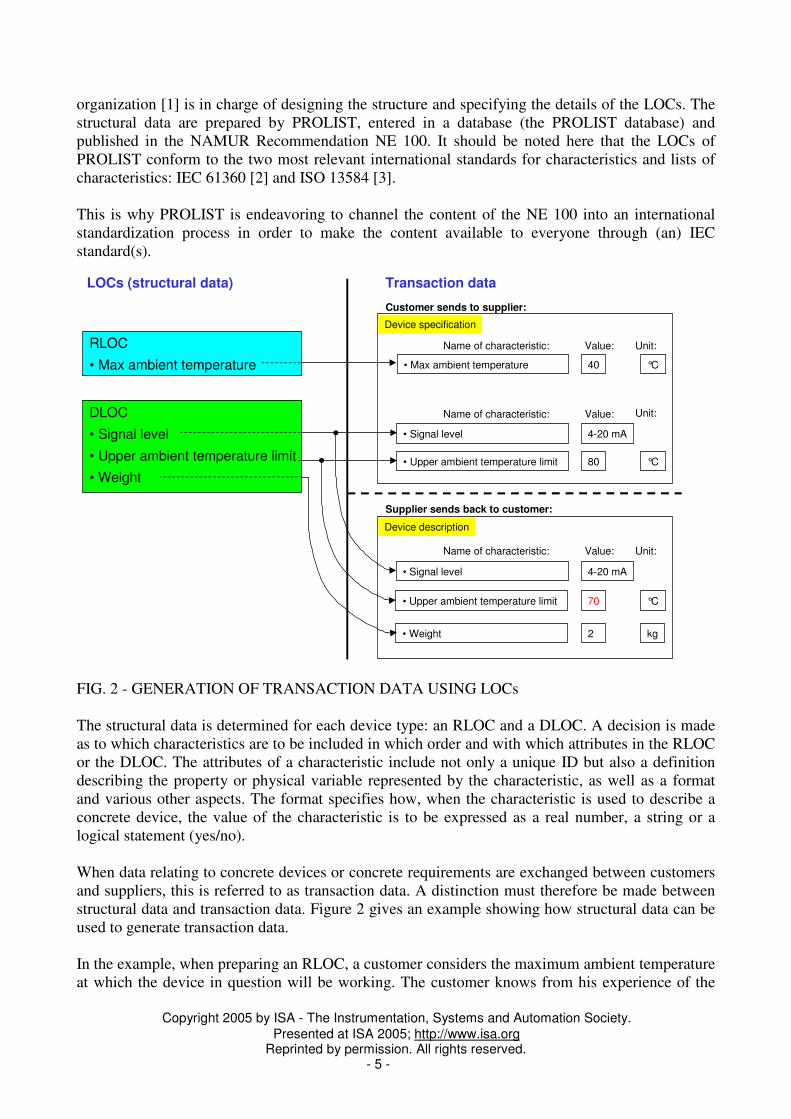
FIG. 2 - GENERATION OF TRANSACTION DATA USING LOCs
The structural data is determined for each device type: an RLOC and a DLOC. A decision is madeas to which characteristics are to be included in which order and with which attributes in the RLOCor the DLOC. The attributes of a characteristic include not only a unique ID but also a definitiondescribing the property or physical variable represented by the characteristic, as well as a formatand various other aspects. The format specifies how, when the characteristic is used to describe aconcrete device, the value of the characteristic is to be expressed as a real number, a string or alogical statement (yes/no).
When data relating to concrete devices or concrete requirements are exchanged between customersand suppliers, this is referred to as transaction data. A distinction must therefore be made betweenstructural data and transaction data. Figure 2 gives an example showing how structural data can beused to generate transaction data.
In the example, when preparing an RLOC, a customer considers the maximum ambient temperatureat which the device in question will be working. The customer knows from his experience of the
LOCs (structural data) Transaction data
RLOC
• Max ambient temperature
DLOC
• Signal level
• Upper ambient temperature limit
• Weight
• Signal level 4-20 mA
Name of characteristic: Value:
• Max ambient temperature 40
Name of characteristic: Value:
°C
Unit:
Device specification
• Upper ambient temperature limit 80 °C
Device description
• Signal level 4-20 mA
Name of characteristic: Value:
• Upper ambient temperature limit 70 °C
• Weight 2 kg
Unit:
Unit:
Customer sends to supplier:
Supplier sends back to customer:

Copyright 2005 by ISA - The Instrumentation, Systems and Automation Society.Presented at ISA 2005; http://www.isa.org
Reprinted by permission. All rights reserved.- 6 -
process that the maximum ambient temperature will be 40°C. He enters this data as the value of thecharacteristic “Maximum ambient temperature”. Regarding the new device itself, the customer inour example has two wishes:- He would like the signal level to be expressed as a 4-20 mA current signal, and- He would like the device to be designed for an upper ambient temperature limit*) of 80°C.These are the values he enters for the characteristics “Signal level” and “Maximum ambient tem-perature”.
A device specification is generated as a result of this data input process. Once the devicespecification has been completed, the customer sends it to one or more suppliers in the form of anXML transmission file. The XML transmission file is automatically generated by his CAE systemin response to the data he has entered via an XML schema which was created in 2004 by PROLISTin collaboration with SAP.
The XML transmission file can then be automatically sent by the CAE system via the Internet tothe suppliers that the customer has selected as recipients. The suppliers can read the XMLtransmission file into their own systems and prepare a (technical) offer using the data thustransferred. To prepare the offer, the supplier uses only the DLOC which, however, must becompleted as fully as possible. In other words, the supplier can only transfer the data of the quoteddevice into the structure of the DLOC which has been already stored in his own internal databasesand which he wishes to transmit to the customer. This is how the device description is generated,which also falls under the category of transaction data.
The device description is converted by the specified XML schema into an XML transmission file inthe supplier’s system and automatically sent to the customer via the internet. The customer canimport the device description directly into his CAE system, for example, which can interpret theXML transmission file. In our example, the customer receives the following information (figure 2):
- The desired signal level of 4-20 mA is confirmed.- The supplier cannot comply with the desired upper ambient temperature limit of 80°C for the
device quoted. He can only offer a device with a certified level of 70°C, and he states this in thedevice description.
- From the many data that it is possible to use to describe a device, we have included the weightin our example, which the supplier has stated to be 2 kg.
By using XML transmission files based on the same XML schema, the customer can compareoffers sent to him by several suppliers and choose the most appropriate one when ordering thedevice. Since each characteristic is labeled with a unique ID, the values of the characteristics in theoffers can easily be evaluated by computer.
Concerning the transaction data, 3 lists of characteristics in all have to be handled:- an RLOC to be completed by the customer only,- a DLOC stating the customer’s wishes which, in practice, will contain only a few entries
(inquiry view), and- a DLOC which the supplier utilizes to describe as fully as possible the device that he is
proposing to the customer (this DLOC also contains CAE-relevant characteristics to cover theimport of the device master data into the CAE system).

Copyright 2005 by ISA - The Instrumentation, Systems and Automation Society.Presented at ISA 2005; http://www.isa.org
Reprinted by permission. All rights reserved.- 7 -
The files which transfer the transaction data from one party to the other contain only the ID and thevalue entered for each characteristic by the customer or the supplier. In our example these are:40°C, 4-20 mA, 80°C, 4-20 mA, 70°C, and 2 kg.
THE PILOT PROJECT
The standardization of characteristics and lists of characteristics is an essential prerequisite, buttesting the exchange of data on the basis of these standards in practice is equally important. In orderto demonstrate the practicability of this data exchange, Bayer Technology Services, Leverkusen,Germany, conducted a pilot project with the aim of realizing an electronic engineering workflowwith the help of equipment manufacturers who already support the work done by PROLIST. Inaddition to the equipment manufacturers, Intergraph (a CAE systems manufacturer) alsocollaborated on the project.
Participating in the pilot project were:• Bayer Technology Services
referred to below as the “customer”, and• ATB,• Endress+Hauser,• Pepperl+Fuchs,• Siemens
referred to below as the “supplier(s)”, and• Intergraph.
FIG. 3 - THE P&I DIAGRAM REALIZED IN THE PILOT PROJECT
Outflow
M
InflowLOASL1100
LICL1000
YCY1000
FIF1000
MOSM1100

Copyright 2005 by ISA - The Instrumentation, Systems and Automation Society.Presented at ISA 2005; http://www.isa.org
Reprinted by permission. All rights reserved.- 8 -
The role of Intergraph, a member of PROLIST, in this project was to demonstrate the automaticdata exchange using the CAE planning tool SmartPlant Instrumentation (formerly INtools).
The pilot project considered a process unit, as illustrated in figure 3. This unit contains 5 PCT loops.
The user (customer) utilized the Spec Sheets that had been developed by Bayer for INtools forinput of his requirements into the CAE system, SmartPlant Instrumentation. These Spec Sheetshave a certain similarity to the S20 Spec Sheets of ISA.
A separate Spec Sheet was used for each device type, i.e. for:- LV asynchronous motor,- vibration level switch,- differential pressure transmitter- positioner- coriolis flowmeter,- remote I/O card input, and- remote I/O card output.
For each device type, the requirements were transferred converted by the CAE system to a devicespecification in the form of an XML transmission file. The workflow set up on the customer side isshown in figure 4. The adapter is used to assign the fields (characteristics) in the database of theCAE system, i.e. the input fields of the Spec Sheets, to the corresponding fields in the XMLtransmission files.
FIG. 4 - WORKFLOW ON THE CUSTOMER SIDE
XML files are not intended to be either generated or read by human beings. XML was designed asa machine-readable format and can only be utilized by computers. For this reason, PROLIST hasprovided a set of tools on a dedicated PROLIST server to enable users, and especially small and

Copyright 2005 by ISA - The Instrumentation, Systems and Automation Society.Presented at ISA 2005; http://www.isa.org
Reprinted by permission. All rights reserved.- 9 -
medium sized enterprises to exchange data by means of XML transmission files, thus making iteasier for them to implement this kind of business process optimization.
The tools, which have been collected into an application package, include• a viewer for visualization of XML files as a table with a block structure,• an editor for writing XML files,• a tool for comparing XML files.
The purpose of the application package is to make tools rapidly available in order to provide “proofof work” and to be able to demonstrate that the data exchange will work in practice. In the pilotproject described, these tools were used by both the customer and the supplier.
Suppliers were thus able to read the XML transmission files sent by the customer, and selected andsized the corresponding devices using the data provided (the transmitted characteristics). Thisresulted in the compilation of offers containing the device data in the form of device descriptionswhich were then converted into XML transmission files using the application package. The XMLfiles were sent to the customer via the internet. The workflow on the supplier side is illustrated infigure 5. The adapter in this case represents the mapping process between the product data base ofthe supplier and the XML schema in the device description.
FIG. 5 - WORKFLOW ON THE SUPPLIER SIDE
The customer was then able to import the data of the devices offered to his CAE system via theXML transmission files. Directly after importing the data, the customer was able to generate theprocess control documentation for the process unit shown in figure 3. Figure 6 shows two of thedocuments to be prepared for this documentation.

Copyright 2005 by ISA - The Instrumentation, Systems and Automation Society.Presented at ISA 2005; http://www.isa.org
Reprinted by permission. All rights reserved.- 10 -
FIG. 6 - LOOP DIAGRAM AND CIRCUITRY LIST OF A DISTRIBUTION BOX
EXPERIENCE GATHERED DURING THE PILOT PROJECT
A complete electronic workflow was set up, thus demonstrating its practicability on the basis of thePROLIST lists of characteristics. The establishment of such an engineering workflow acrossdifferent systems and system worlds will always encounter certain difficulties at firstimplementation. This is quite simply a fact of life. Also, during the course of the project, Intergraphswitched to SmartPlant Instrumentation Version 7.
The experience gained can be summarized as follows:− The support of IT specialists is indispensable for the realization of the adapters (interfaces
between the XML files and the respective in-house systems).− The performance of the application package used requires some improvement.− Automatic adapters for data transmission into and out of the in-house systems must either be
improved or have yet to be developed. This includes catalog systems and systems for offergeneration on the supplier side, CAE, procurement and maintenance systems on the user side.
On the supplier side, work is progressing at full speed on the adapters for the in-house catalogsystems. The interface from and to SmartPlant Instrumentation proved problematical. This was dueto the different granularities in the CAE system and the XML files. This problem will occur in oneform or another in every system that was not established from the first on the basis of XML filestructures.

Copyright 2005 by ISA - The Instrumentation, Systems and Automation Society.Presented at ISA 2005; http://www.isa.org
Reprinted by permission. All rights reserved.- 11 -
SUMMARY AND OUTLOOK
The report used examples to illustrate the advantages to be gained from using standardizedcharacteristics and lists of characteristics in planning and maintenance processes employing state ofthe art CAE systems. The difference between structural and transaction data was pointed out.PROLIST generates structural data in the form of lists of characteristics for different types ofprocess control devices and publishes these through the NE 100.
One of the first pilot projects that was initiated by Bayer Technology Services and which used thelists of characteristics published in the NE 100 was described, as well as the results obtained. OtherPROLIST members have completed pilot projects to test the practicability of the NE 100 lists ofcharacteristics or are currently conducting such projects. In addition to the companies listed in thereport, further PROLIST members (BASF, Innotec, Krohne and Wacker-Chemie) eitherparticipated in the stated project or are involved in other ongoing projects. The current list ofPROLIST members can be found on the Internet at www. prolist.org.
The next step will be to disseminate the idea of standardized product data exchange and to push theinternational standardization process. Success will only have been achieved when the electronicworkflow has become established in the field. Essential preliminary work has been completed:
• The provision of standardized characteristics and lists of characteristics through PROLIST,including the data model and its implementation in the PROLIST database,
• The international standardization process has been initiated through a work proposal to IECand is being supported by PROLIST and its members,
• Leading providers of business process solutions, such as SAP and Intergraph, are currentlyimplementing the technology,
• The electronic workflow has undergone prototype testing (proof of work).
Once the approach has become generally accepted, the following step will be to implement andutilize the standardized characteristics and lists of characteristics in commercial business processes.This will achieve universal usability of the data and reduce the duplication of data in companies’systems still further. PROLIST is currently preparing to take up this challenge. Standardizedcharacteristics reduce the complexity of business processes.
REFERENCES
[1] - Löffelmann, G., and P. Zgorzelski. "Lists of Characteristics for Optimization of theProcesses in Automation and Process Control." Proceedings of ISA EXPO 2004 held 5-7 October2004, in Houston, Texas. Paper #TP04ISA308.[2] - IEC (ed.), IEC 61360 “Standard data element types with associated classification schemefor electric components”[3] - ISO (ed.), ISO 13584 “Industrial automation systems and integration – Parts library”
NOMENCLATURE
NAMURInternational user association of process control technology in chemical and pharmaceutical

Copyright 2005 by ISA - The Instrumentation, Systems and Automation Society.Presented at ISA 2005; http://www.isa.org
Reprinted by permission. All rights reserved.- 12 -
industries. Its member companies come from the chemical, pharmaceutical and petrochemicalindustries in the German speaking region. Contractor companies working for the named industriesare also eligible for membership. Two thirds of the members are based in Germany. The rest arelocated in Spain, Austria, Hungary, Switzerland, Belgium and the Netherlands. Manufacturers ofprocess control technology, hardware and software are not eligible as members.
NAMUR Recommendations (NE) and Worksheets (NA)These are experience reports and working documents prepared by NAMUR for its members amongprocess control users. Their use is optional.
Process Control Technology (PCT) or Process Control System (PCS)An expression used by the NAMUR members which covers electrical equipment, instrumentationand control equipment, and process control technology.
Characteristic (or Property)A defined parameter suitable for the description and differentiation of objects. A characteristicdescribes one detail of a given object.
List of characteristics (LOC)Describes by means of characteristics the features of one equipment type. An LOC is also used forcompiling the requirements a planned device should fulfill.
ABBREVIATIONS
CAE Computer Aided EngineeringDLOC Device List of CharacteristicsERP Enterprise Resource PlanningIEC International Electrotechnical CommissionISO International Standards OrganisationIT Information TechnologyLOC Lists of CharacteristicsNAMUR Interessengemeinschaft Prozessleittechnik der chemischen und pharmazeutischen
IndustrieNE NAMUR RecommendationPCS Process Control SystemPCT Process Control TechnologyRLOC Requirements List of CharacteristicsXML eXtensible Markup Language