implementation progress of capstone phase ii · 2016. 10. 26. · maneuvering water taxi tcf map...
TRANSCRIPT

Implementation Progress of Capstone Phase II Summary for 2003
May 2004
Aviation Technology Division
The MITRE Corporation’s Center for Advanced Aviation System Development

2
Acknowledgement
The University of Alaska Anchorage, Aviation Technology Division gratefully acknowledges contributions to pilot surveys and accident classification for this report by the Institute of Social and Economic Research, University of Alaska Anchorage.

Highlights of the Implementation Progress of Capstone Phase II
From March through December 2003 the Capstone program made significant progress toward implementation of capabilities designed to improve commercial aviation in southeast Alaska.
During 2003 Capstone has:
• Gained approval, via Special Federal Aviation Regulation (SFAR) No. 97, for the first commercial use of a Global Positioning System / Wide Area Augmentation System (GPS/WAAS) navigation system as sole means of navigation.
• Obtained FAA Certification of the first Wide Area Augmentation System.
• Developed, flight-tested and gained approval for stand alone GPS approaches and departures at four southeast Alaska Airports.
• Developed and gained approval for lower IFR Minimum Enroute Altitudes for over 1,500 miles of airspace in Southeast Alaska.
• Obtained the first FAA Certification of a Highway In The Sky (HITS) system.
• Obtained certification of the Capstone Phase II avionics by FAA Supplemental Type Certificate (STC), covering multiple makes, models, and series of aircraft.
• Begun developing ground infrastructure and awarded contracts for subsequent development and implementation.

1
Implementation Progress of Capstone Phase II
Summary for 20031
1 Introduction
Capstone is a joint initiative by the FAA Alaska Region and the aviation industry to improve aviation safety and efficiency in Alaska by using new technologies. FAA started Phase I of the Capstone program during 2000 in the watershed of the Yukon and Kuskokwim rivers of southwest Alaska – the Y-K Delta. In March 2003, the FAA began Phase II in southeast Alaska. This report summarizes Phase II’s progress in 2003.
1.1 Background
Capstone Phase II is installing a suite of IFR-capable avionics in southeast Alaska commercial aircraft, building ground infrastructure for aircraft surveillance and up-link of weather and flight information, installing automated weather observation systems and remote ATC voice communication sites, and increasing the number of airports served by instrument approaches. Capstone is also making important changes in air space requirements to reduce minimum enroute altitudes on some airways so that suitably equipped aircraft can provide greater air transportation access to cities and villages in southeast Alaska in poor weather. The FAA hopes these improvements will reduce the number of mid-air collisions, controlled-flight-into-terrain (CFIT) accidents, and weather-related accidents while lowering weather-related restrictions that affect routine and emergency air transport.
The program focuses on passenger and cargo operations under Parts 133 and 135 of Federal Aviation Regulations (FAR; 14 CFR, Chapter 1). Part 135 operators typically fly air taxi, commuter, and sightseeing (flightseeing) operations. Part-133 operators use helicopters for various non-passenger activities such as helicopter logging. Aircraft owned by these carriers will be eligible to receive Capstone Phase II avionics. Float planes, flying under Visual Flight Rules (VFR) in the summer season, account for a large share of FAR Part-135 operations in southeast Alaska.
1.2 Description of the Capstone Phase II Area
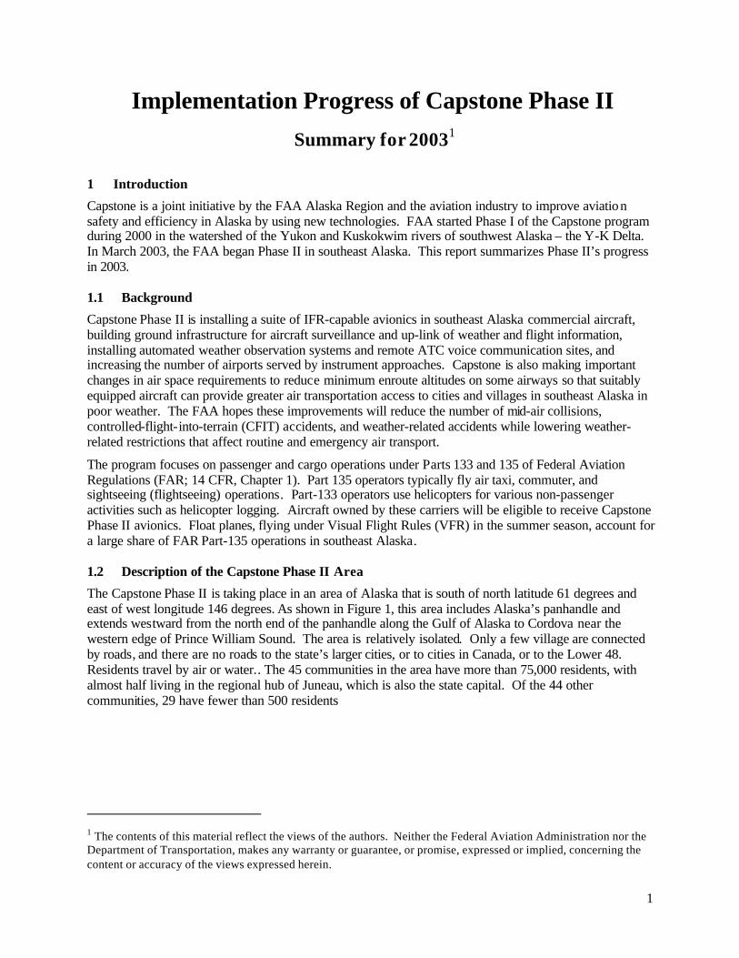
The Capstone Phase II is taking place in an area of Alaska that is south of north latitude 61 degrees and east of west longitude 146 degrees. As shown in Figure 1, this area includes Alaska’s panhandle and extends westward from the north end of the panhandle along the Gulf of Alaska to Cordova near the western edge of Prince William Sound. The area is relatively isolated. Only a few village are connected by roads, and there are no roads to the state’s larger cities, or to cities in Canada, or to the Lower 48. Residents travel by air or water.. The 45 communities in the area have more than 75,000 residents, with almost half living in the regional hub of Juneau, which is also the state capital. Of the 44 other communities, 29 have fewer than 500 residents
1 The contents of this material reflect the views of the authors. Neither the Federal Aviation Administration nor the Department of Transportation, makes any warranty or guarantee, or promise, expressed or implied, concerning the content or accuracy of the views expressed herein.
2
Figure 1. Southeast Alaska Major Communities
1.3 Aviation Access before Capstone
Southeast Alaska has 84 airport facilities—24 airports, 8 heliports, and 52 seaplane bases. Figure 2 summarizes the scheduled and unscheduled Alaska operations to, from and within the Phase II area in 2002-2003 by commercial operators with some scheduled service2. Figure 3 subdivides the flights between Phase II airports by their airport of origin.
2 These statistics are derived from T-100 segment data compiled by the Bureau of Transportation Statistics from the Form 4100 reports filed by Far Part 121 and Part 135 air carriers that have scheduled operations.

3
From the Phase II Areato Other Parts of Alaska
24%
From Other Parts of Alaskato the Phase II Area
25%
Within thePhase II Area
51%
Figure 2. Intra-Alaska Flights To or From Capstone Phase II Airports
others23%
Skagway8%
Sitka (IFR Hub)6%
Hoonah (Proposed IFR)8%
Ketchikan (IFR Hub)10%
Gustavas (IFR)4%
Kake Seaplane Base4%
Juneau (IFR Hub)37%
Figure 3. Origins of Flights between Capstone Phase II Airports
Weather, terrain, and communications are primary limitations on aviation access in southeast Alaska. Weather hazards in include several conditions that create poor visibility and low ceilings. The area is a marine environment with extremely variable weather and frequent storm systems with low ceilings and fog. Many destinations in the area do not have weather reporting facilities. Operators depend on area forecasts and pilot reports to make Go/NoGo decisions. Some flight routes have long distances between weather stations; for example, the route from Yakutat to Sitka is 201 nautical miles between weather stations. The terrain is extremely mountainous , which often causes low ceilings enroute due to fog and clouds trapped in the area’s numerous valleys. These low ceilings reduce flight dispatch capabilities due to the Minimum Enroute Altitude (MEA). The mountains and the valley and inlet locations of most airports restrict aircraft-to-ground and line-of-sight communications abilities.
4
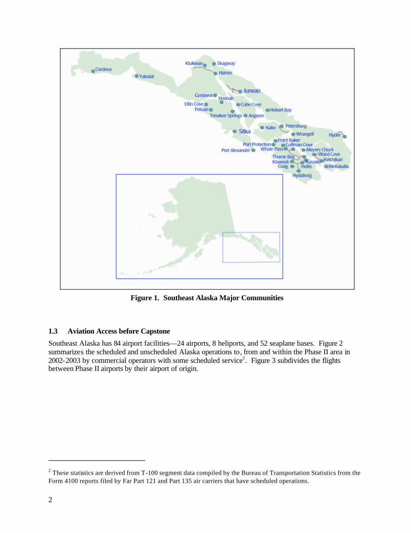
1.4 Accidents Prior to Capstone
There were 231 accidents within the Phase II area reported by the National Transportation Safety Board from 1990 through 2002. The Capstone Phase II Baseline Report divided these into the categories and sub-categories described in Figure 4 and the result is shown in Figure 5. The inner pie shows all accidents divided into major categories. The extensions show more detail within the major categories. For example, difficulties with off-airport landing sites may occur with water landings by the large number of float planes flying under Visual Flight Rules (VFR) in the summer.
Capstone avionics, training and information can help pilots avoid CFIT accidents, collisions between aircraft, and some accidents where flight information is a factor. From 1990 to 2002 in southeast Alaska, about 25 percent—58 of the total 231 accidents—are from causes specifically targeted by Capstone Phase II, and might have been prevented if the Capstone program had been in place. These causes are highlighted in the figure with a dark band. Also highlighted are fuel management accidents which the new avionics may help prevent.
Categories of the 54 fatal accidents in southeast Alaska from 1990 through 2002 are shown in Figure 6. Capstone could potentially have prevented a much larger fraction of the accidents that were fatal. More than half were due to causes that Capstone avionics, training, and data are intended to address. Most fatal accidents were CFIT accidents, either in cruise flight or on approach or departure. Fatalities in float plane accidents are often due to pilot or passenger drowning.
Basic Cause Categories 1. Mechanical: Engine failure, inoperable control surfaces,
failed landing gear or floats, propeller or shaft failure. 2. Navigation: Controlled Flight into Terrain (CFIT) while en
route is often associated with reduced visibility and small navigational errors. Some CFIT accidents are due to pilots being off-course.
3. Traffic: Usually mid-air collisions. Also includes ground or water accidents from last-moment avoidance of other aircraft and from jet blast on airport surface.
4. Flight Information: Usually accidents that result from inadequate weather information and are often caused by icing and sometimes poor visibility but rarely convective weather. (Surface winds contributing to take-off or landing accidents have been included under take-off or landing rather than here.)
5. Fuel: Accidents caused by fuel mismanagement. 6. Flight Prep: Accidents caused by a variety of poor flight
preparation measures, including failure to insure that cargo is tied down and within the aircraft’s weight and balance limits and failure to check whether fuel has been contaminated by water.
7.Takeoff: Accidents during take-off, including pilots’ failure to maintain control in wind, improper airspeed, waterway debris, hazards at remote lakes, rivers without markings or moorings, poor runway conditions and obstacles at off-runway sites.
8. Landing: Accidents during landing, including pilots’ failure to maintain control in wind, improper airspeed, waterway debris, hazards at remote lakes, rivers without markings or moorings, poor runway conditions and obstacles at off-runway sites.
9. Other: Includes colliding with watercraft or ground vehicles, hitting birds and pilots under the influence of alcohol or drugs.
10. Unknown: Missing aircraft, cause not determined.
Cause Sub-Categories Runway: Accidents on take-off or landing related to runway or waterway conditions such as potholes, submerged obstacles the runway Site: unusual hazards of water or off-runway sites Water taxi: collisions with objects (not a/c) while taxiing on the ocean, rivers or lakes Maneuvering: Typically, stalling the aircraft while maneuvering
Capstone Relevant Sub-Categories or Categories
Weather: Accidents where the availability of weather information was a factor. CFIT: Controlled Flight into Terrain (or Water) accidents TCF: Terrain Clearance Floor violation - CFIT that occurs on approach or departure. Map: Accidents where the pilot did not know aircraft’s location Midair: Midair Collisions between aircraft. Runway Collisions: between aircraft on the ground or water. Fuel: Accidents caused by fule mismanagment.
NOTE:
This analysis is from UAA-ISER’s Phase II Baseline Report and reflects the applicability of Phase I avionics plus TCF violations and runway collisions. It is updated here only to reflect fuel management enhancements available with the Chelton avionics. Chelton also includes other capabilities such as glide-range guidance that might help with emergency landings and Highway In The Sky (HITS) guidance which may help with complex navigtion. Re-analysis of the historical accidents in light of additional capabilities will be performed in the coming year.
Figure 4. Accidents Categories defined in the Phase II Baseline Report

5
Weather
CFIT
Site Runway
Site
Maneuvering Water Taxi
TCF Map
Runway Collision
Midair
Unknown 4
Flight Prep 6
Other 23 Fuel 6
Landing 65
Take-off 33
Mechanical 42
Traffic 14
Navigation 23
Flight Info15
231
Capstone Phase II Focus
Figure 5. All Accidents in the Phase II area by Category3, 1990 – 2002
Figure 6. Fatal Accidents in the Phase II area, by Category3, 1990 – 2002
3 This analysis is from UAA-ISER’s Phase II Baseline Report and reflects the applicability of Phase I avionics plus TCF violations and runway collisions. It is updated here only to reflect fuel management enhancements available with the Chelton avionics. Chelton also includes other capabilities such as glide-range guidance that might help with emergency landings and Highway In The Sky (HITS) guidance which may help with complex navigtion. Re-analysis of the historical accidents in light of additional capabilities will be performed in the coming year.
Weather
CFIT
Maneuvering
TCF Map Midair
Flight Info 7
Navigation 16
Mechanical 8 Take-off 3
Landing 1 Fuel 1
Other 7
Flight Prep 1
Unknown 4
54
Traffic 6
Capstone Phase II Focus

6
2 The Capstone Phase II Program
Capstone seeks near-term safety and efficiency gains in aviation by accelerating implementation and use of modern technology. The capabilities of Capstone Phase II target four serious safety problems in southeast Alaska:
• CFIT accidents (within the navigation category)
• Accidents associated with aircraft traffic – especially mid-air collisions
• Inadequate flight information – especially weather information
• Inadequate infrastructure to support IFR operations
2.1 Program Overview
Capstone implements new technologies enabling pilots to cope with terrain, traffic conflict and weather hazards. These technologies also allow dispatchers/operators better means to monitor their aircraft and give air traffic controllers expanded surveillance coverage to provide Air Traffic Control (ATC) services.
The first objective supporting this goal is to allow the use of GPS/WAAS technology for the en route portion of flights on routes in Alaska outside the operational service volume of ground based navigation aids. This requires changes to Federal Aviation Regulations, and the results are threefold. First, it permits satellite navigation as the only means of navigation needed onboard the aircraft. Second, it allows the use of lower Minimum Enroute Altitudes (MEAs) than those currently based on ground-based navigation aids. In this process, Capstone used current Terminal Instrument Procedures (TERPS) criteria for enroute airways; however Capstone applied it to the use of the GPS/WAAS navigation signal. Low enroute RNAV GPS MEAs will eventually cover the entire region and become available publicly. Third, it promotes safety by creating and promoting a usable IFR environment that allows an IFR option for pilots that have had to fly predominantly in the visual flight rules (VFR) environment that exists today.
The second objective is to establish new departure and approach procedures, initially between Juneau, Haines, Hoonah and Gustavus airports and, with operator acceptance, expand to other parts of southeast Alaska. This allows safer airport-to-airport access. These procedures will be developed as “specials” and achieve the lowest possible minimums for RNAV/GPS non-precision approaches by applying waivers with special training and equipment requirements to current TERPS criteria.
Activities supporting these objectives include certifying and installing state-of-the-art GPS/WAAS avionics, amending air routes to achieve lower MEAs, developing special approach and departure procedures, filling communication gaps, and ensuring accomplishment of all supporting training and operational approval guidance for operators as well as FAA oversight personnel.
Capstone is also providing additional services in southeast Alaska to improve overall safety. This initiative promotes better situational awareness of weather and other traffic by expanding the ADS-B ground infrastructure to southeast Alaska and adding data link avionics. This will provide a data link to include Automatic Dependent Surveillance-Broadcast (ADS-B) and Flight Information Services-Broadcast (FIS-B). The objective is to use multiple means to alert pilots of possible traffic conflicts and weather hazards. Adding a universal access transceiver (UAT) to the avionics will enable display of other ADS-B aircraft (cockpit display of traffic information or CDTI). Installing an ADS-B ground system will provide track information to controllers and Automated Flight Service Station (AFSS) specialists. The UAT data link will also be used to relay weather information to the cockpit. Multilateration and Traffic Information Services – Broadcast (TIS-B) are being evaluated for possible inclusion in the future to complete the surveillance picture in the cockpit.

7
2.2 Systems and Capabilities
Capstone is using a full communications, navigation, and surveillance/air traffic management (CNS/ATM) perspective to establish the system supporting Phase II operations. Figure 7 depicts Phase II capabilities. Avionics are being certified and installed to enable instrument approaches/departures and GPS/WAAS navigation on lower-altitude airways. This also requires the publishing of new navigation charts and instrument departure and approach procedures for use by pilots and controllers. New communications transceiver sites support this by preventing gaps when MEAs are lowered below the line-of-sight of existing communication sites. Finally, new weather observation facilities are included at airports to meet the requirements of commercial IFR operations.
There are two airborne configurations available to the operators: a primary flight display (PFD) multifunction display (MFD) pair developed by Chelton and a Garmin MFD similar to the Phase I avionics. The operators can select the configuration that best suites their operations and aircraft. Both are coupled with WAAS-GPS receivers capable of increased accuracy and integrity to enable Capstone area navigation (RNAV) capabilities. Automated Weather Observation Station (AWOS), Remote Communications Air-Ground (RCAGs) facilities and Remote Communications Outlets (RCOs) complement and support these airborne components. Phase II also includes traffic situation awareness displays in the Juneau Air Traffic Control Tower (ATCT) and Juneau AFSS, connection into existing air traffic automation and display facilities at Anchorage ARTCC (Air Route Traffic Control Center) through interconnecting telecommunications (e.g., ANICS), and ground broadcast transceiver (GBT) sites which communicate with the aircraft avionics.
Capstone Phase II plans to integrate these new and existing systems and equipment to complement RNAV services and provide a lower altitude, usable IFR infrastructure. Together, these systems and equipment should enhance operations and safety in the southeast Alaska airspace system.
Lower MEAs and GPS Instrument
Approach
GPS/WAAS Location
UAT Radio
EFIS Primary Flight Display and Multi-Function Display HITS/Moving Maps 2-D / 3-D Terrain Proximity Weather and Flight Information Other Aircraft
– Chelton –
Navigation Databases
ADS -B Aircraft
Locations
Ground-Based Transceivers (GBTs), Networks
ADS-B Other Aircraft Locations
FIS-B Weather & Flight Information TIS-B Aircraft Locations from Ground Surveillance
Tower Operations
Company Flight
Monitoring
Air Traffic Control
Aircraft Locations
from Radar or Multilateration
Weather & Flight Information
from Multiple Sources
Each Equipped Aircraft
VHF Voice Radio
RCAG/RCO
(( ))
VHF Voice Radio
AWOS
(( ))
OR
Multi-Function Display Moving Maps 2-D Terrain Proximity Weather and Flight Information Other Aircraft
– Garmin –
Figure 7. Capstone Phase II Systems and Capabilities

8
2.2.1 Ground System
The ground system will expand the Capstone Phase I data link infrastructure into southeast Alaska. It consists of the ATC automation within Anchorage ARTCC and new remote GBT sites. It will expand ATC surveillance for radar-like-service and provide weather information to the cockpit and tracking data to enable flight following for commercial operators and FAA AFSS specialists. Communication sites and weather reporting sites are discussed in following sections. A multilateration surveillance system may be installed later in Juneau, supplementing ADS-B in the terminal area for aircraft that have transponders but not ADS-B. Surveillance of these non-Capstone aircraft could then be provided to controllers, and with TIS-B, could also be provided to pilots. Surface surveillance (including vehicles) is being evaluated in Juneau.
2.2.1.1 Voice Communications
Communications enhancements include new RCAGs to fill ATC communication gaps, enable new RNAV operations, and lower many minimum enroute altitudes. Initial communications improvements to support Capstone Phase II are shown in Figure 8 and will include a new RCAG facility at the south end of Stephens Passage for direct pilot-controller voice contact and at Mt. Robert Barron for improvements along Lynn Canal and over Icy Bay. Flight Service support will also be improved with the installation of an RCO radio in the same vicinity. Further communications improvements are expected as needs are documented.4
Figure 8. Voice Communications Coverage Before Capstone, with Inset showing
Coverage Improvement by Capstone Phase II
4 Current and future voice communications coverage in the Cordova area were not available at the time of this report and are not shown in Figures 7 and 8.

9
2.2.1.2 Next Generation Ground Based Transceivers , and ATC and Broadcast Services
New GBT sites5 have been chosen to provide surveillance coverage (Figure 9) at, around, and between the key airports with new GPS approaches. Capstone is also choosing other sites to create and expand a low altitude RNAV route structure in southeast Alaska. Initially, 14 sites have been identified. Surveillance data will be linked back to the MicroEARTS automation system at Anchorage ARTCC. The data will be used for ATC and distributed to other users including air carrier operations centers (AOCs) and local operators, via the ETMS system, and Aviation Flight Service Station (AFSS) for flight following. FIS-B (and eventually, TIS-B) will also be available via the Capstone Communications Control Server (CCCS) via the GBTs. FIS-B weather and other NAS data will be uplinked in southeast Alaska as it is the Bethel, YK Delta area.
Figure 9. Surveillance Coverage with New GBTs at 3000 Feet ASL
2.2.1.3 Automated Weather Observation Sites
Commercial air carriers need weather observations for destination airports before performing an instrument approach. Observations are also useful inputs to the overall weather picture because additional sites improve the accuracy and detail of weather forecasts in the region. New Automated Weather Sensor System (AWSS) sites will be installed and report weather conditions including temperature, dew point, wind, altimeter setting, visibility, sky condition, and precipitation. The weather reports from these sites will be available by phone, over radio on aviation frequencies and, once connected to the national weather collection system, can be extracted from other weather data at AFSS, other NAS systems, and over the internet or via FIS-B.
5 Surveillance sites for the Cordova area were not available at the time of this report and are not shown in Figure 9.
10
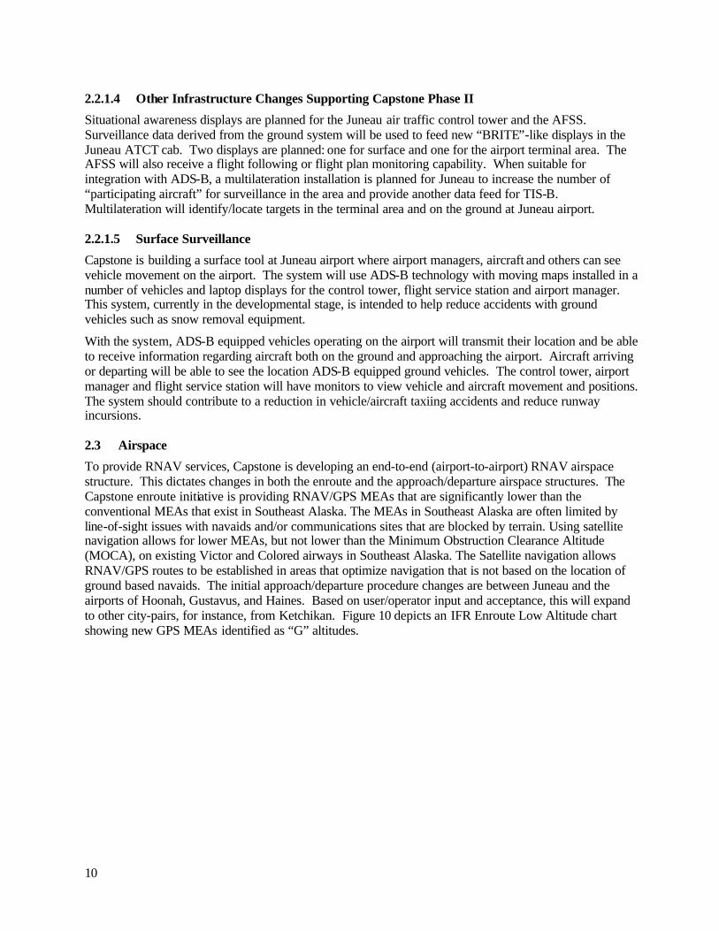
2.2.1.4 Other Infrastructure Changes Supporting Capstone Phase II
Situational awareness displays are planned for the Juneau air traffic control tower and the AFSS. Surveillance data derived from the ground system will be used to feed new “BRITE”-like displays in the Juneau ATCT cab. Two displays are planned: one for surface and one for the airport terminal area. The AFSS will also receive a flight following or flight plan monitoring capability. When suitable for integration with ADS-B, a multilateration installation is planned for Juneau to increase the number of “participating aircraft” for surveillance in the area and provide another data feed for TIS-B. Multilateration will identify/locate targets in the terminal area and on the ground at Juneau airport.
2.2.1.5 Surface Surveillance
Capstone is building a surface tool at Juneau airport where airport managers, aircraft and others can see vehicle movement on the airport. The system will use ADS-B technology with moving maps installed in a number of vehicles and laptop displays for the control tower, flight service station and airport manager. This system, currently in the developmental stage, is intended to help reduce accidents with ground vehicles such as snow removal equipment.
With the system, ADS-B equipped vehicles operating on the airport will transmit their location and be able to receive information regarding aircraft both on the ground and approaching the airport. Aircraft arriving or departing will be able to see the location ADS-B equipped ground vehicles. The control tower, airport manager and flight service station will have monitors to view vehicle and aircraft movement and positions. The system should contribute to a reduction in vehicle/aircraft taxiing accidents and reduce runway incursions.
2.3 Airspace
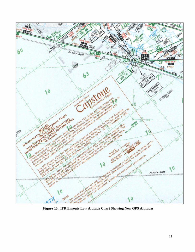
To provide RNAV services, Capstone is developing an end-to-end (airport-to-airport) RNAV airspace structure. This dictates changes in both the enroute and the approach/departure airspace structures. The Capstone enroute initiative is providing RNAV/GPS MEAs that are significantly lower than the conventional MEAs that exist in Southeast Alaska. The MEAs in Southeast Alaska are often limited by line-of-sight issues with navaids and/or communications sites that are blocked by terrain. Using satellite navigation allows for lower MEAs, but not lower than the Minimum Obstruction Clearance Altitude (MOCA), on existing Victor and Colored airways in Southeast Alaska. The Satellite navigation allows RNAV/GPS routes to be established in areas that optimize navigation that is not based on the location of ground based navaids. The initial approach/departure procedure changes are between Juneau and the airports of Hoonah, Gustavus, and Haines. Based on user/operator input and acceptance, this will expand to other city-pairs, for instance, from Ketchikan. Figure 10 depicts an IFR Enroute Low Altitude chart showing new GPS MEAs identified as “G” altitudes.
11
Figure 10. IFR Enroute Low Altitude Chart Showing New GPS Altitudes

12
Figure 11 shows how Hoonah, Haines, Juneau, Gustavus departure and approach RNAV procedures (including holding procedures and fixes) are being modified or created to provide a low altitude IFR structure in SE Alaska. New procedures have been published as Special (or Public, as appropriate) procedures.
Figure 11. Depiction of Initial Departure and Approach RNAV Structure

13
2.4 Aircraft Systems
During 2003, installation of government-provided avionics began for up to 200 commercially operated aircraft (estimated 150 fixed-wing and 50 rotor-wing) in and around southeast Alaska. The intent of the Phase II avionics is to increase pilot situational awareness and increase navigational performance during IFR and VFR operations. A description of the avionics is provided below. The avionics package will include the following functions, in stages:
Stage 1 (initial avionics – Primary Flight and Navigation Displays)
• Primary flight display functions, including heading, pitch and roll attitude, airspeed, vertical speed, etc., as well as flight path.
• Display 3-dimensional views of terrain. The system will include terrain alerting and warning system (TAWS) that meets TSO-151a, Class B.
• Navigation display functions using GPS/WAAS including position, course, waypoints and fixes, groundspeed, etc.
Stage 2 (full avionics to operate air-to-air and with ground system – Universal Access Transceiver)
• ADS-B air-to-air traffic targets along with TIS-B targets (when TIS-B becomes available) on a multi-function navigation display and primary flight display when appropriate. Traffic warnings will also be provided.
• Display FIS-B information (text and graphics).
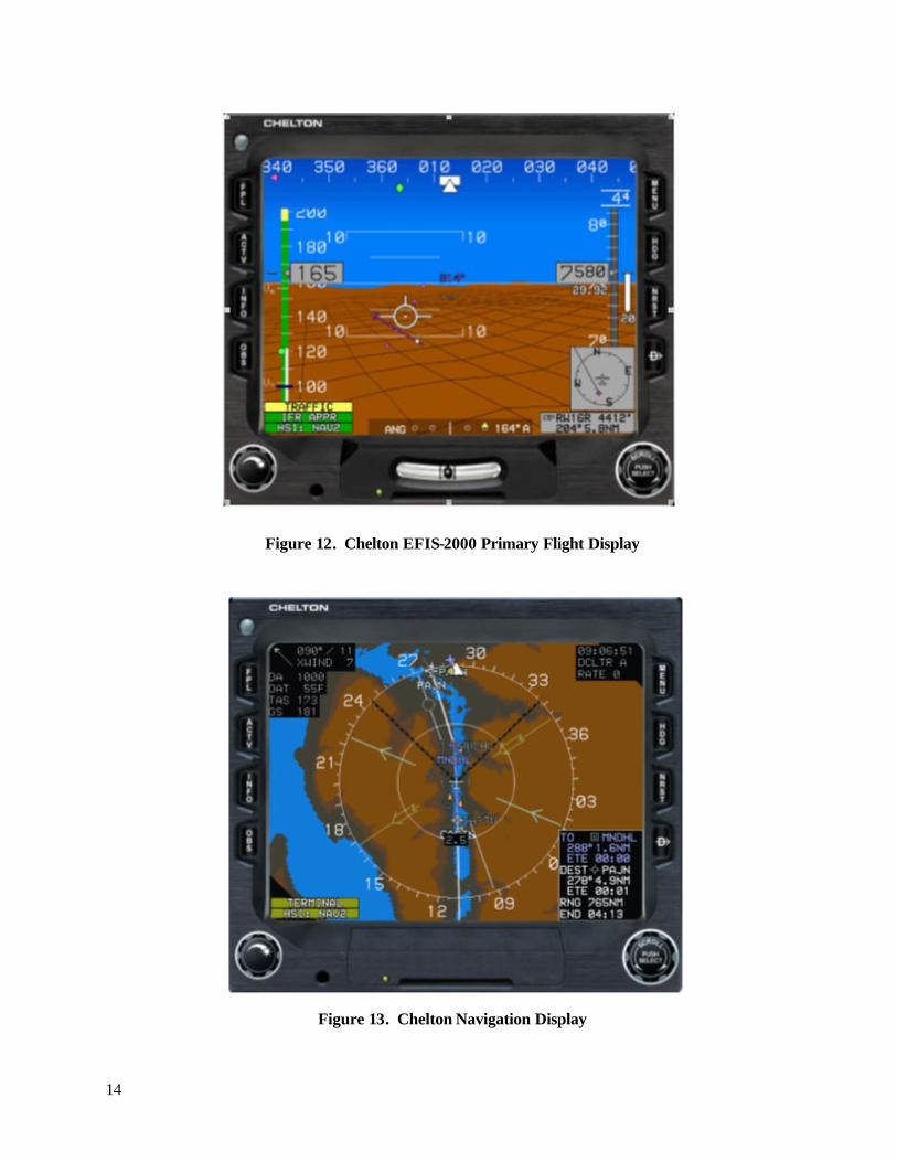
Chelton Flight Systems (formerly Sierra Flight systems) was selected to provide its EFIS-2000 Primary Flight Display (PFD) (Figure 12), its Navigation Display (Figure 13), and supporting avionics. Garmin-AT Corporation was selected to provide their MX20 Multifunction Display (Figure 14) with supporting avionics, which is often being chosen by helicopter operators to better meet their special operational requirements at lower workload. Both avionics sets include GPS-WAAS receivers. Garmin has also been selected to provide a stand-alone UAT ADS-B system which will be used with both types of avionics. The Capstone program will oversee integration of these systems with the ground system and provide avionics units to individual aircraft operators. Installation of these avionics is covered under a multiple make, model, and series FAA Supplemental Type Certificate (STC).
14
Figure 12. Chelton EFIS-2000 Primary Flight Display
Figure 13. Chelton Navigation Display

15
Figure 14. Garmin MX-80 Multi-Function Display

16
3 Capstone II Progress in 2003
2003 was an important year for the Capstone Phase II Program. Developing infrastructure for such a complex system is usually a multi-year task in aviation; however, many key elements of the Phase II system were developed, certified and became operable in less than a year. Progress continues on the remaining elements. The following paragraphs present the progress attained during 2003.
3.1 Voice Communications
The RCAG sites were selected, surveys accomplished, and construction began in 2003. RCAGs are planned for Gunnuk Mountain, Cape Spencer and Robert Baron. Gunnuk Mountain will be the first RCAG to go online in 2004.
3.2 Ground Based Transceivers
The site selection, surveys , and construction began for the 14 new GBTs. Figure 9 (in section 2.2.1.2) shows the locations. Capstone awarded a contract for the new GBTs, which are currently undergoing testing. An installation schedule will be developed following those tests.
3.3 Automated Weather Observation Stations
Hoonah currently has an operating AWOS that will be part of the Phase II program. Angoon is scheduled to receive an AWOS in 2004. This will bring the total number of weather facilities in southeast Alaska to 18. Current nearby stations are tabulated in Figure 15, and many of the station locations are shown in Figures 16, 17, and 18.
Location Station Identifier Type of Reporting Annette PANT ASOS Elfin Cove PAEL Apaid Cordova PACV ASOS Gustavus PAGS AWOS/Apaid Haines PAHN ASOS Hoonah PAOH AWOS/Apaid Hydaburg PAHY AWOS Juneau PAJN ASOS/FCWOS/LAWRS Kake PAFE AWOS Ketchikan PAKT ASOS Klawock PAKW ASOS Metlakatla PAMM AWOS Petersburg PAPG AWOS Port Alexander PAAP Apaid Sitka PASI ASOS Skagway PAGY ASOS Wrangell PAWG AWOS/FCWOS Yakutat (not shown on map below) PAYA ASOS/WSO
Figure 15. Southeast Alaska Weather Facilities by Location

17
Figure 16. PACV – Cordova Figure 17. PAYA – Yakutat
Figure 18. All Other Weather Reporting Facilities

18
3.4 Tower Displays
The new displays have not been installed as of the end of 2003. They are planned for installation after ADS-B surveillance becomes available
3.5 Airspace
Capstone Phase II accomplished a number of airspace “firsts” in 2003. The year saw the first commercial use of a Global Positioning System (GPS)/Wide Area Augmentation System (WAAS) navigation system and the first commercial use of airspace optimization, providing access to airspace that would otherwise be inaccessible with conventional avionics. Stand-alone GPS Approaches and Departures were developed, flight tested and approved for Gustavus, Haines, Hoonah and Juneau. Minimum Enroute Altitudes were developed and approved for over 1,500 miles of airspace in Southeast Alaska.
The FAA issued SFAR No. 97, allowing the use of Global Positioning System/Wide Area Augmentation Systems for the en route portion of flights on routes in Alaska outside the operational service volume of ground based navigation aids. Highway In The Sky (HITS) synthetic flight path guidance was certified as part of the new avionics. This provides a series of target boxes that the pilot can use to navigate in lateral and vertical dimensions along departure, enroute or arrival paths.
3.6 Aircraft Systems
A total of 16 aircraft were completed in 2003 of the 173 currently scheduled for modification. One non-commercial aircraft (University of Alaska) was modified in 2002. Of the 16 modified aircraft, three are IFR and Class 1 (twin engine piston) aircraft. The majority of aircraft equipage for Capstone Phase II will take place during the winter of 2004-2005. (The winter is the “off” tourist season since many of the operators focus on the tourist trade.) Installation progress is shown in Figure 19.
Phase II-modified aircraft at the end of 2003 represented 7.5 percent of the aircraft fleet in Southeast Alaska and 9.8 percent of the scheduled modifications.
Figure 19. Aircraft Equipped with Capstone Phase II Avionics in 2003

19
3.7 Phase II Operator Training
The University of Alaska Anchorage (UAA) provided initial Capstone training for pilots using a “train the trainer” approach. UAA has an agreement with the FAA Capstone office to provide initial training to the air carriers’ trainers on the operation and use of the Capstone system. The University provided each operator with an 8400.10 (Air Carrier Inspector Handbook) compliant training program. The training program outlines ground training, flight training, checking, and recordkeeping. Beginning in spring of 2003, UAA provided initial training for each of the operators. UAA timed the training to coincide as closely as possible to the delivery of a carrier’s first Capstone-equipped aircraft. The typical operator had two people receiving 16 hours of classroom training with the avionics training device. The initial training evaluated each participant and their ability to properly use the Chelton PFD/MFD avionics. All Capstone operators currently operating with Chelton Phase II avionics received initial training during the 2003 or in the first few months 2004. Progress on training pilots to do training is shown in Figure 20.
In 2004 UAA also entered into an agreement with the FAA to train key maintenance personnel on the Chelton Phase II system. The training focuses on field maintenance with an emphasis on troubleshooting, removing and replacing inoperative components, and updating software.
Figure 20. Air Carrier Trainer-Pilots Trained by UAA during 2003
3.8 Pilot Surveys
Pilots operating Capstone-equipped aircraft were surveyed in fall 2003. As stated earlier in the report, 2003 was primarily an infrastructure development year and, therefore, not a full year of operations. A limited number of pilots familiar with Capstone were available at the time of the survey. Ten pilots responded and were interviewed. Analysis does not provide significant findings due to the small number of respondents. The responses provided below are indicative of pilots’ perceptions of the hazards and their acceptance of the Phase II equipment. The questions on hazards are listed and followed by a breakdown of pilot responses in Figure 21. A question-set on using Capstone is followed by a breakdown of pilot responses in Figure 22. We plan to conduct broader surveys in the future as the Capstone Phase II program expands.

20
1. How many times during the past year have inaccurate weather forecasts caused you to encounter instrument meteorological conditions which you didn’t expect? (First graph – Figure 21)
2. How many times during the past year have deteriorating ceilings or visibility made you unsure of your own position relative to the surrounding terrain? (Second graph – Figure 21)
3. During the past year, how many times have you unexpectedly seen other aircraft close enough to you that you felt it created a collision hazard? (Third graph – Figure 21)
4. During the past year, how many times might your go/no go or routing decisions have been improved if you would have had access to real time weather or Special Use Airspace status? (Last graph – Figure 21)
Unexpected IMC
30%
30%
40%
Unsure of Terrain40%
30%
30%
Collision Hazard
10%
20%
60%
10%
Go/No-go Wx & SUA
20%
40%
20%
20%
Daily Weekly Monthly <Monthly Never
Figure 21. Pilot-reported Frequencies of Problems Potentially Addressed by Capstone Phase II
5. For each of the functions of Capstone avionics listed below, please tell us how often you use that feature, how easy it is to use, and how helpful it is to you? (Figure 22)

21
70%
20%
10%
60%20%
20% 10%
70%
20%
80%
10%
10%
40%
30%
20%
10%20%
70%
10%
90%
10%
50%40%
10% 10%
80%
10%
40%
20%
30%
10%
40%
20%
40%
10%
10%
40%
40%
90%
10%
60%10%
20%
10%
40%
50%
10%
Terrain
Flight Planning
Navigation
GPS Approaches
Fuel Management
Frequency of Use Ease of Use Usefulness
RoutineRareNeverNo Ans.
Easier Similar Harder No Ans.
VerySomeNotNo Ans.
Don't Know
Figure 22. Pilot-reported Frequency of use, Ease of use, and Usefulness of Capstone capabilities
These responses indicate the initial capabilities of the Capstone Phase II program are relevant to pilot’s perceived needs, that pilots use the capabilities, and that the usability and usefulness of Capstone are regarded favorably.

22

23
4 Next Steps
In 2004, the program will increase the number of modified aircraft operating in southeast Alaska. Infrastructure development, such as increased numbers of GBTs, AWOSs, and RCAGs along with an increase in the number of Capstone-equipped aircraft, should allow for a more comprehensive Interim Report, analyzing the impact of Phase II on flight safety and efficiency in southeast Alaska.
In 2004 and following years ADS-B and FIS-B capabilities will be put in place enabling traffic and weather in the cockpit of equipped aircraft. Through the GBT network this will provide surveillance information for air traffic control in the Anchorage Air Route Traffic Control Center, in the Juneau Air Traffic Control Tower, and in Flight Service Stations. Vehicles will be equipped with ADS-B to evaluate improvements in airport-surface safety at Juneau, and the use of multilateration surveillance will be explored for better integration of transponder-equipped non-Capstone aircraft into Capstone Phase II operations.

24

25
5 Acronyms and Abbreviations ADS-B Automatic Dependent Surveillance – Broadcast
AFSS Aeronautical Flight Service Station
AGL Above Ground Level
ANICS Alaska NAS Inter-Facility Communications System
ARTCC Air Route Traffic Control Center
ATC Air Traffic Control
ATD Aviation Technology Division UAA
AWOS Automated Weather Observation System
AWSS Automated Weather Sensor System
CCCS Capstone Communications Control Server
CDTI Cockpit Display of Traffic Information
CFIT Controlled Flight into Terrain
CNS/ATM Communications, Navigation Surveillance/Air Traffic Management
FAA Federal Aviation Administration
FAR Federal Aviation Regulation
FIS-B Flight Information Service-Broadcast
FSDO Flight Standards District Office
GPS Global Positioning System
GBT Ground Based Transmitter
HITS Highway In The Sky (navigation guidance)
IFR Instrument Flight Rules
MDA Minimum Descent Altitude
MEA Minimum Enroute Altitude
MFD Multifunction Display (an IDU capable of multiple screens)
MSL Mean Sea Level
MTBF Mean Time Between Failures
NPA Non-Precision Approach
PAI Principle Avionics Inspector
PFD Primary Flight Display
PMI Principle Maintenance Inspector
POI Principle Operations Inspector
RCO Remote Communications Outlets
RCAG Remote Communications Air Ground Facilities

26
RNAV Area Navigation
RNP Required Navigation Performance
SFAR Special Federal Aviation Regulation
STAR Standard Terminal Arrival Routes
STC Supplemental Type Certificate
SUA Special Use Airspace
TCF (violation of) Terrain Clearance Floor (on approach or departure)
TERPS Terminal Enroute Procedures
TIS-B Traffic information Service-Broadcast
TSO Technical Standard Order
UAA University of Alaska Anchorage
UAT Universal Access Transceiver
VFR Visual Flight Rules
VHF Very High Frequency
VNAV Vertical Navigation
WAAS Wide Area Augmentation System