Improve Complexity Management with Model-Based …worrydream.com/ClimateChange/refs/4_Christian_Guss_Improve... · “In developing a next-generation ventilator, which uses a different
Sehr geehrte Damen und Herren, Mein Name ist Christian Guß. Ich bin Applikationsingenieur bei The MathWorks und ich demonstriere heute einen Ansatz, die Komplexität in der Software und Systementwicklung mittels modelbasierter Softwareentwicklung besser zu bewältigen.� Ich habe Mechatronik studiert und war vor meiner Zeit bei MathWorks als Consultant in verschiedenen Rollen bei verschiedensten Firmen unter anderem als Softwareentwickler, Requirementsingenieur und Tester. Mein Schwerpunkt liegt im Model-Based Design, der Verifizierung und Validierung von Software und der automatischen Generierung von Produktionscode unter Beachtung von industrieller Standards und Normen. Ich bin heute mit meinem Kollegen Herrn Hopfenzitz hier. Wir haben draußen einen Stand, wo Sie uns gerne in den Pausen und nach den Vorträgen besuchen und diskutieren können. Wir freuen uns auf Sie.
3
Agenda
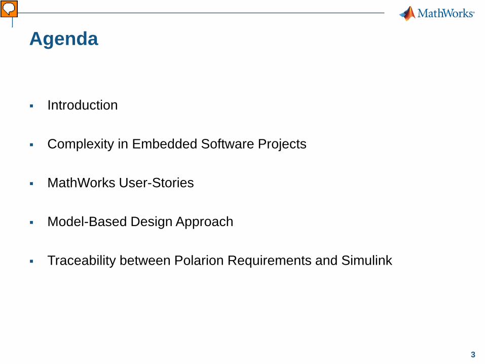
Introduction Complexity in Embedded Software Projects
MathWorks User-Stories
Model-Based Design Approach
Traceability between Polarion Requirements and Simulink
Vorführender
Präsentationsnotizen
Nach der kurzen Vorstellung möchte ich gerne erläutern was ich mit Komplexität in Embedded Software Projekten meine und was die Herausforderungen dabei sind. Um das Ganze etwas greifbarer zu machen präsentiere ich eine UserStory aus der Medizintechnik. Anschließend möchte ich Ihnen anhand des V-Modells darstellen was in den Augen von MathWorks Model-Based Design bedeutet und wie es dabei hilft komplexe Softwareprojekte besser zu bewältigen. Während dessen zeige ich Ihnen anschaulich wie die Requirements-Management Lösung von Polarion mit der MathWorks-Toolchain zusammenspielt und welche Synergien sich daraus bilden lassen.
4
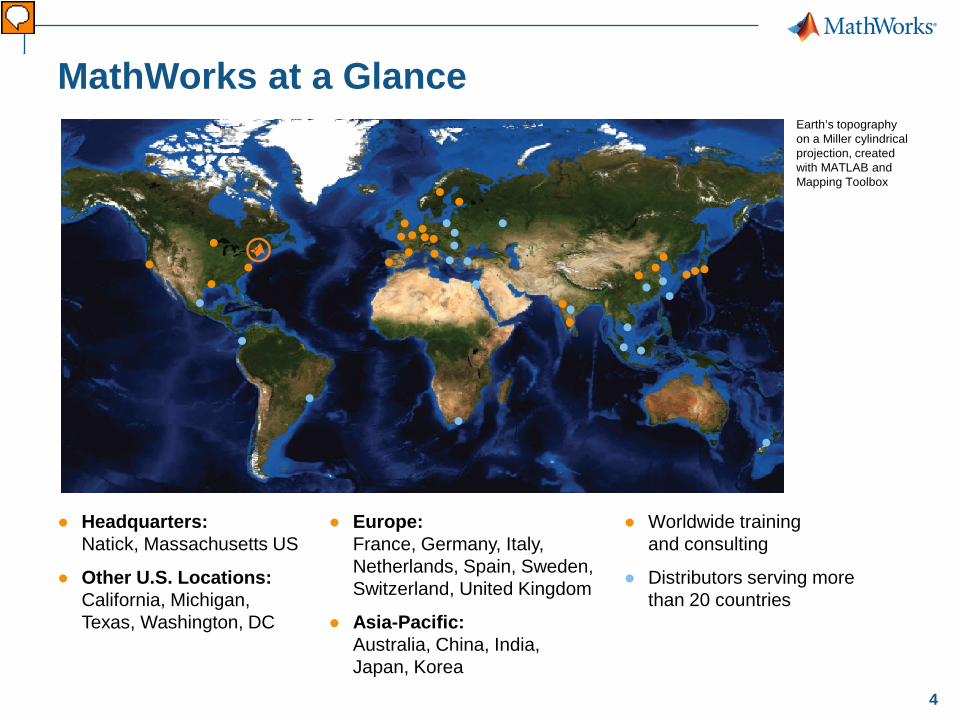
MathWorks at a Glance Earth’s topography on a Miller cylindrical projection, created with MATLAB and Mapping Toolbox
● Headquarters: Natick, Massachusetts US
● Other U.S. Locations: California, Michigan, Texas, Washington, DC
● Europe: France, Germany, Italy, Netherlands, Spain, Sweden, Switzerland, United Kingdom
● Asia-Pacific: Australia, China, India, Japan, Korea
● Worldwide training and consulting
● Distributors serving more than 20 countries
Vorführender
Präsentationsnotizen
MathWorks hat weltweit über 3000 Mitarbeiter. Hauptstandort ist in Natick USA. Das liegt in der Nähe von Boston. Darüber hinaus gibt es weltweit Standorte von MathWorks und eine Reihe von Ditributoren.
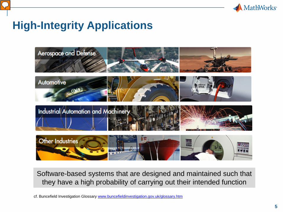
Software-based systems that are designed and maintained such that they have a high probability of carrying out their intended function
Vorführender
Präsentationsnotizen
Software ist in immer mehr Systemen ein fester Bestandteil und übernimmt immer mehr Funktionen des Gesamtsystems. Das sichere Funktionieren dieser Systeme ist dabei von enormer Bedeutung. Von High-Integrity Applications spechen wir, wenn ein funktionaler Ausfall von solchen Systemen großen wirtschaftlichen Schaden verursacht oder gar Menschenleben gefährdet. Wir finden solche Systeme in vielen Bereichen, wie der Luft und Raumfahrt, dem Automobilbau, der Energie- und Medizintechnik aber auch in Fertigungsstraßen z.B.
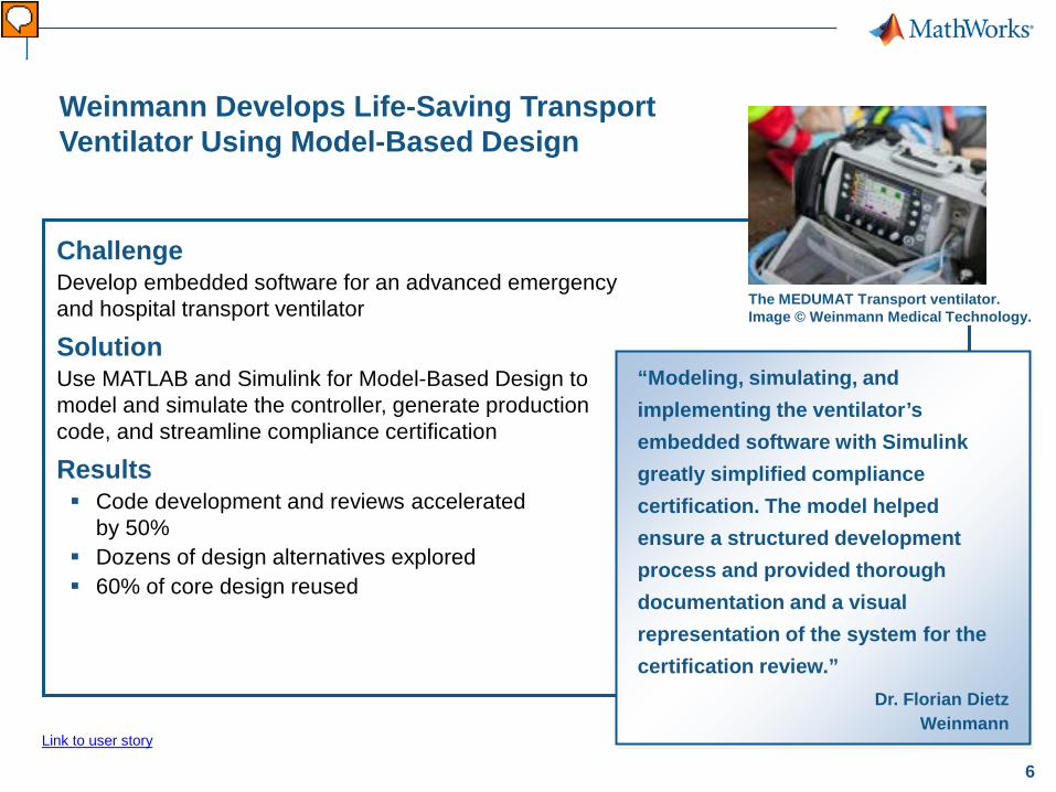
Weinmann Develops Life-Saving Transport Ventilator Using Model-Based Design
Challenge Develop embedded software for an advanced emergency and hospital transport ventilator
Solution Use MATLAB and Simulink for Model-Based Design to model and simulate the controller, generate production code, and streamline compliance certification
Results Code development and reviews accelerated
by 50% Dozens of design alternatives explored 60% of core design reused
“Modeling, simulating, and implementing the ventilator’s embedded software with Simulink greatly simplified compliance certification. The model helped ensure a structured development process and provided thorough documentation and a visual representation of the system for the certification review.”
Primary Industry: Medical devices Secondary Industries: NA Product Capabilities: Mathematical modeling, Algorithm development, System design and simulation, Embedded code generation, Verification, validation, and test Applications: Embedded systems, Control systems, Digital signal processing Products Used: MATLAB, Simulink, DSP System Toolbox, Embedded Coder, Fixed-Point Toolbox, Simulink Fixed Point, Simulink Verification and Validation, Stateflow, Infineon C166 MCU, Texas Instruments C2000 MCU Country: Germany Weinmann Develops Life-Saving Transport Ventilator Using Model-Based Design The MEDUMAT Transport ventilator moves a mixture of oxygen and air into and out of the lungs of patients who require breathing support. Developed by Weinmann Medical Technology, MEDUMAT Transport is designed for use in emergency care and during transport for intrahospital or interhospital transfers. As an emergency medical device deployed in a wide range of operating conditions, the MEDUMAT Transport must be portable, versatile, and exceptionally reliable. Weinmann engineers used Model-Based Design with MATLAB® and Simulink® to develop the embedded software for MEDUMAT Transport. This approach not only streamlined production; it also helped Weinmann work with TÜV SÜD to certify MEDUMAT Transport to ISO/IEC 62304, ISO 10651-3, DIN EN ISO 13485, and DIN EN ISO 14971 standards. “MEDUMAT is orders of magnitude more complex than earlier ventilators that we have developed,” says Dr. Florian Dietz, head of predevelopment emergency medicine at Weinmann. “Model-Based Design with MATLAB and Simulink enabled us to handle the increased complexity, and it was instrumental in our achieving compliance certification. Working with models instead of handwritten code makes the embedded software easier to maintain and reuse, and helps us explain the technology to a certification authority.” The Challenge MEDUMAT Transport has a variety of sensors to measure pressure, flow, temperature, and molar mass (used to measure oxygen concentration). These sensors, combined with advanced pneumatics and electromagnetic valves, make MEDUMAT Transport the most advanced—and the most complex—ventilator that Weinmann has ever developed. Weinmann engineers recognized that their traditional process, in which embedded software was hand coded, was not feasible for this project. “Compliance certification would be extremely complex if the code were all handwritten, because we would have no way to demonstrate the whole system,” says Dietz. “Maintenance, too, would be a challenge because it’s a huge effort for a colleague to understand so many lines of code without extensive documentation.” In addition to developing embedded software for the device’s 16-bit Infineon® XC161CJ microcontroller (MCU), Weinmann engineers needed to develop a subsystem that used a Texas Instruments™ TMS320C2810™ MCU to process signals from a flow sensor positioned near the patient’s endotracheal tube. To find the optimal algorithms for this system, the engineers needed to evaluate numerous design alternatives. “Modeling, simulating, and implementing the ventilator’s embedded software with Simulink greatly simplified compliance certification. The model helped ensure a structured development process and provided thorough documentation and a visual representation of the system for the certification review.” - Dr. Florian Dietz, Weinmann The Solution Weinmann used MATLAB and Simulink to model, simulate, and help verify the embedded software for MEDUMAT Transport and to simplify the compliance certification process. Weinmann engineers developed a Simulink plant model, which included hardware components as well as a mechanical model of human lungs. The team used Simulink and Stateflow® to model the controller and its state machines, including one state machine that tracks standby, startup, shutdown, and other operating modes and a second that manages the entire ventilation process. The system-level controller model served as the top level in a hierarchy of subsystems, which were also modeled in Simulink, supporting the fundamental requirement for a modular software design and architecture. After developing and simulating the design as a floating-point model, the engineers used Fixed-Point Toolbox™ and Simulink Fixed Point™ to convert it to fixed point for deployment to the 16-bit MCU. In parallel with the MCU development, the engineers used DSP System Toolbox™ to develop digital filters and algorithms for the proximal flow sensor that calculates the gas flow velocity to the patient. After running closed-loop simulations of the controller and plant in Simulink, the team used Embedded Coder™ to generate production code for the control system and the sensor signal processing subsystem. They deployed the code to the Infineon and TI MCUs, respectively. Weinmann engineers performed unit tests on each subsystem within the model, using Simulink Verification and Validation™ to analyze model coverage. Most safety standards now explicitly require or recommend the use of Model-Based Design. As a result, Weinman will leverage its investment in MATLAB and Simulink on future projects requiring certification. MEDUMAT Transport is now in production and in use by medical personnel in Europe, Asia, and Australia. The Results ■ Code development and reviews accelerated by 50%. “Model-Based Design enabled us to generate 100% of the embedded software, excluding the drivers,” says Dietz. “We also spent about 50% less time on internal review, because we worked with the models instead of low-level source code.” ■ Dozens of design alternatives explored. “With MATLAB and Simulink we evaluated up to 40 signal processing algorithms, which we could not have done if we were hand coding,” notes Dietz. “In MATLAB we analyzed and plotted the results produced by the different algorithms to identify the best one for our design.” ■ 60% of core design reused. “In developing a next-generation ventilator, which uses a different processor, we will reuse about 60% of the Simulink model for MEDUMAT Transport,” says Dietz. “We estimate that this reuse will reduce development time on the new project by an additional 30%.” To learn more about Weinmann Medical Technology, visit www.weinmann.de/en/home
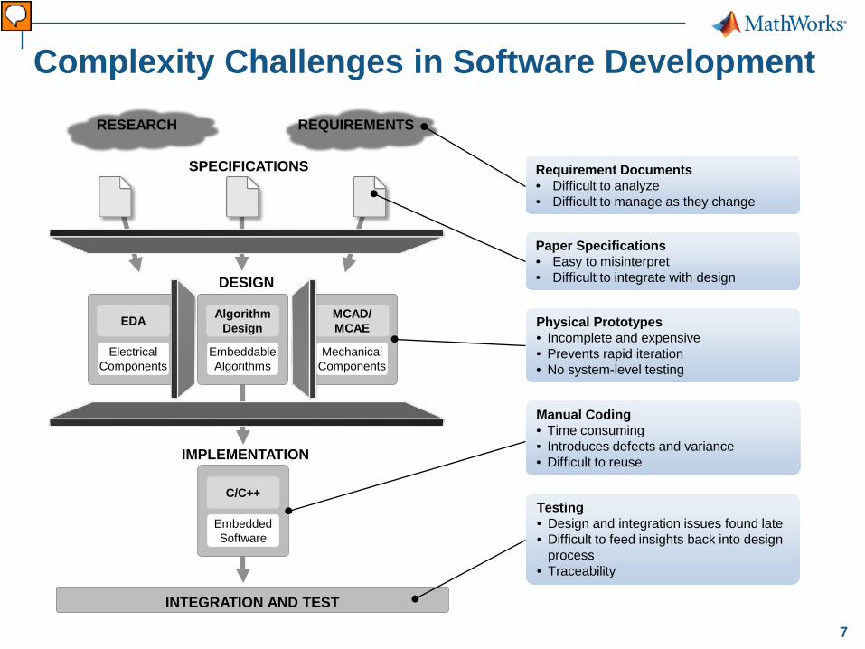
Requirement Documents • Difficult to analyze • Difficult to manage as they change
Paper Specifications • Easy to misinterpret • Difficult to integrate with design
Manual Coding • Time consuming • Introduces defects and variance • Difficult to reuse
Testing • Design and integration issues found late • Difficult to feed insights back into design
process • Traceability
Embeddable Algorithms
Algorithm Design Physical Prototypes
• Incomplete and expensive • Prevents rapid iteration • No system-level testing
Complexity Challenges in Software Development
Vorführender
Präsentationsnotizen
Let’s look at a simplified representation of a traditional development to understand why it is difficult to find errors early in designing multi-domain systems. [ Short Version ] [Advance] The complexity in systems is dictating more complex requirements. These more complex requirements are difficult to analyze and to manage as they change. [Advance] Complexity of specifications makes them easy to misinterpret. It is also difficult to trace specs to the design. [Advance] The controller algorithms are manually tuned on a prototype or on the actual system. Prototypes often are not easily available or let you test only part of the overall system. [Advance] Coding is done manually, often resulting in errors when design is not interpreted correctly. [Advance] And the integration and test phase is where the problems show up, since that is the first time systems are integrated. The result is that errors are found late and are expensive to fix. [Advance] The different tools used throughout the development process make it difficult to understand how the whole system will work and how different components will interact with each other. If different groups are working on different parts of the projects, there is also a communication problem between them. [Advance] So let me introduce Model-Based Design and explain how it will help you detect errors early and therefore allow you to design innovative products with high performance faster and cheaper. Model-Based Design is a Computer Aided Engineering (CAE) solution for MATHEMATICALLY describing how the equipment will work. [Advance] [Long Version] Generally, a typical process for a project to design an embedded control system involves iterative cycles of these phases: Specification development Design and Implementation Integrate and Test [Advance] This design approach starts with requirements and specifications which are typically text documents. With any document, interpretation is subjective to the reader, so misinterpretation of the design intent is common. In addition, engineers involved might not realize that the document is missing crucial information until the project reaches a later stage when hardware becomes available. [Advance] In the design and implementation stage, components for each subsystem (for example: mechanical electrical, controls, embedded software) are designed in different tools that do not necessarily facilitate system level analysis of how the different components will interact with each other, and how the product will work in the operating environment. [Advance] Testing occurs only when each component has been implemented and then integrated into a prototype. Prototypes are expensive and time-consuming to create – you can only make a limited number of prototypes and most likely you will take the path that ensures early success; typically a modest variation of previous products. To be clear, physical prototyping is ALWAYS required, however, physical prototyping limits the number of potential designs you will consider. You may pass over the truly innovative approach because of the perceived risk. With a physical prototype, you attempt to meet all of your design specification requirements, but you will not know until you begin testing it. [Advance] So integrating and testing the design only with prototypes means both integration errors and some component errors are only found at this late stage of the development process. Then the time-consuming and costly activity of isolating the source of the error and then fixing it needs to occur. In the worst case you discover the requirements were wrong when the product is already deployed in the field. In this case you need to go through the whole design process, costing you not only time, money but your reputation with your best customers. [Advance] The different tools used throughout the development process make it difficult to understand how the whole system will work and how different components will interact with each other. [Advance] So as you see with this process you find errors late, and that leads to less performance, more cost, and longer time to bring the product to market – exactly the opposite of what we need to do to be successful, as we discussed in the previous slides. So let me introduce Model-Based Design and explain how it will help you detect errors early and therefore allow you to design innovative products with high performance faster and cheaper. Model-Based Design is a Computer Aided Engineering (CAE) solution for MATHEMATICALLY describing how the equipment will work. [Advance] (use as needed) Some other drawbacks of this approach include: Changing design specifications – At some point, requirements may evolve. Understanding the impact to the project is difficult. Will the design still work as you originally intended? Will you need to develop different physical prototypes? Writing code for the embedded system. If the specification document is incomplete or subject to interpretation, errors will likely show up in code. At this point, backtracking these problems will take considerable time and will likely involve some rework of earlier phases. In addition, hand coding is subject to errors.
8
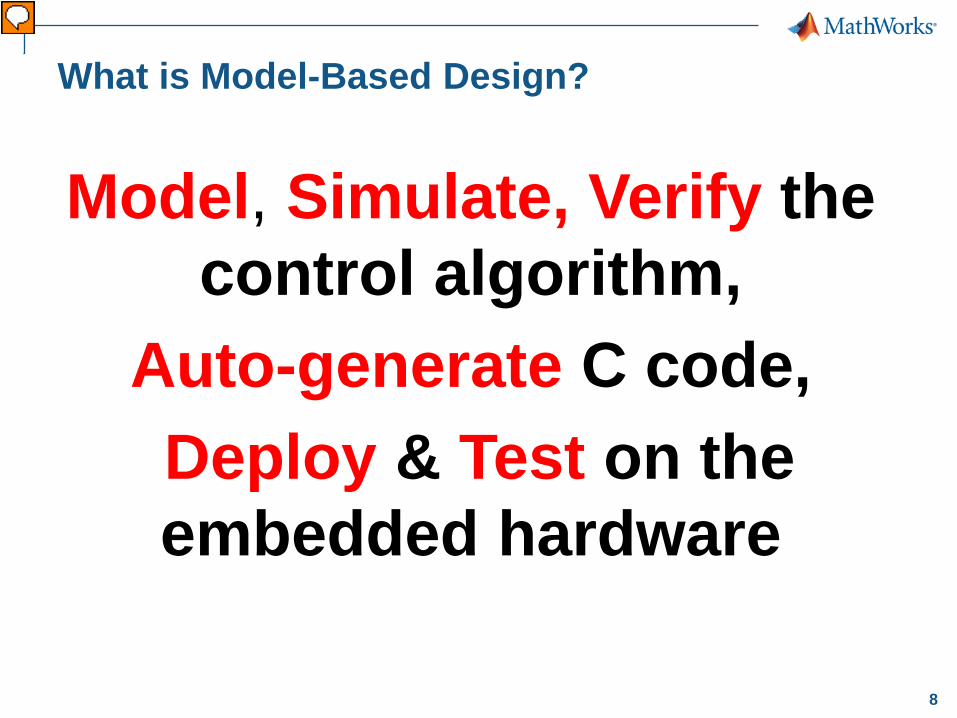
What is Model-Based Design?
Model, Simulate, Verify the control algorithm,
Auto-generate C code, Deploy & Test on the embedded hardware
Vorführender
Präsentationsnotizen
Herunterbrechen der Komplexität durch abstrakte Modellierung, automatischer Code Generierung, sowie der durchgängigen Konsistenz sämtlicher relevanten Artefakte. Ebenso relevant ist das Arbeiten mit iterativ inkrementellen Ansätzen und dem frühen Validieren und Verifizieren von Teilergebnissen auf Komponentenbasis aber auch auf Systemebene. All diese Schritte werde ich Ihnen gern anhand des bekannten V-Modells demonstrieren. Aber zunächst ein Blick in die Tools von Mathworks…
9
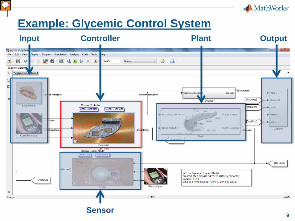
Example: Glycemic Control System Input Output Plant
Sensor
Controller
Vorführender
Präsentationsnotizen
Hier sehen Sie die Oberfläche von Simulink. Ein Tool von MathWorks zur grafischen Modellierung und Spezifikation von Systemen. Sie sehen ein Modell eines Geräts zur Regelung des Blutzuckers für Diabetespatienten. Eine typische regelungstechnische Aufgabe. Die Eingangsvektoren sind die Benutzereingaben, aber auch die Zufuhr an Kohlenhydraten durch die Nahrung. [Click] Durch ein solches Modell sind wie in einer WhiteBox sämtliche Größen beobachtbar. In der Realität ist das meist schwieriger, da die Größen erst gemessen und sichtbar gemacht werden müssen. All das können wir uns hier bequem darstellen lassen oder zu weiteren Analysezwecken einfach mitloggen. [Click] Jede Nahrungszufuhr hat einen Einfluss auf den Metaolismus des Körpers. Regelungstechniker nennen das die Strecke. Die relevante Funktionsweise der Stecke wird ebenfalls modelliert und steht als Block in unserem Modell zur Verfügung. [click] Wo wir schon von Reglung sprachen, gibt es auch hier eine Rückführung der zu regelnden Größe. In unserem Fall den Blutzuckerspiegel, welcher durch einen Sensor gemessen wird. [click] Zu guter letzt fehlt noch ein Element. Der Regler selbst. Das Herz des Systems, welche alle Fäden zusammen führt und die Regelung des zugeführten Insulins übernimmt. Aufgrund von Benutzereingaben über die zugeführte Nahrungsmenge und den Blutzuckerspiegel führt der Controller die notwendigen Berechnungen und Schritte zum Einspritzen des Insulins in den Körper durch. Das ist unser System. Auf höchster Abstraktionsebene spezifiziert. [click]
10
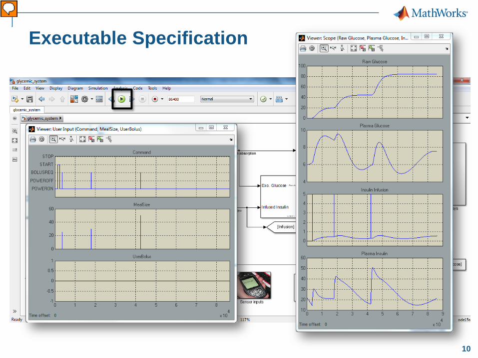
Executable Specification
Vorführender
Präsentationsnotizen
Aber das ist noch nicht alles. Durch einen klick auf den „Run“ Button wird das Modell über die Laufzeit simuliert. [click] Sämtliche Zustandsdaten, ob Input, Output oder Zwischenwerte sind über der Zeit sichtbar und können erstmals analysiert werden. Damit habe ich eine „Ausführbare Spezifikation“, welche mir früh im Entwicklungsprozess hilft Designvarianten zu vergleichen. [click] Auf der linken Seite sind die Eingaben des Benutzers über der Zeit aufgetragen. Sie sehen, dass er nach Mahlzeiten einen extra Bolus an Insulin anfordert. [click] Auf der rechten Seiten sehen Sie die Zustandsdaten des Systems. �-Die gesamt aufgenommenen Kolenydrate.�-Den Blutzuckerspiegel -Das injizierte Insulin über der Zeit, sowie -Das Insulin im Blut Doch wo kommen die ganzen Berechnungen her? [cklick]
11
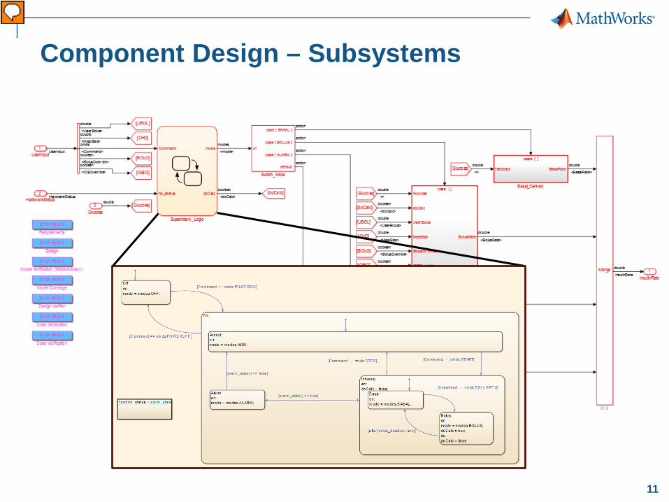
Component Design – Subsystems
Vorführender
Präsentationsnotizen
Hier ist ein Blick in den Modellblock des Controllers dargestellt. Sie sehen eine Zustandsmaschine, welche die Betriebszustände kontrolliert. In den restlichen Blöcken sind die Regler für die Berechnung der Insulinrate modelliert.
12
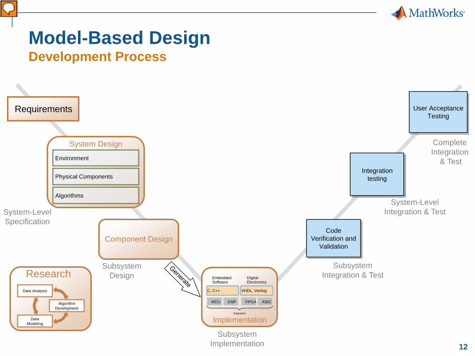
Model-Based Design Development Process
System-Level Specification
Subsystem Design
Subsystem Integration & Test
System-Level Integration & Test
Complete Integration
& Test
Code Verification and
Validation
Integration testing
User Acceptance Testing
Requirements
Subsystem Implementation
DSP FPGA ASIC
Embedded Software
Digital Electronics
C, C++ VHDL, Verilog
Implementation Integration
MCU
Data Modeling
Algorithm Development
Data Analysis
Research
System Design
Physical Components
Environment
Algorithms
Component Design
Vorführender
Präsentationsnotizen
Basis für die heutige Betrachtung des Entwicklungsprozess mit Model-Based Design ist das traditionelle V-Modell, welches Sie hier in der obigen Folie sehen können Es beginnt mit den System Anforderungen und Spezifikationen auf der linken oberen Ecke. Ausgehend von diesen erfolgt die Durchführung des Systemsdesigns und eine weitere Verfeinerung im Rahmen der Aufsplittung des Systemdesigns in feinere Untergruppen (Komponenten). In der Implementierungsphase erfolgt die Umsetzung der Subsysteme auf die Zielhardware. Auf der rechten Seite des V-Modells sind dann die Integrations- und Validierungsschritte bis hin zu den finalen Abnahmetests dargestellt. Eine Möglichkeit das V-Modell zu interpretieren ist, dass diese Schritte in zeitlicher Reihenfolge nacheinander abgearbeitet werden und die Tests erst ganz zum Schluß passieren. <KLICK>
13
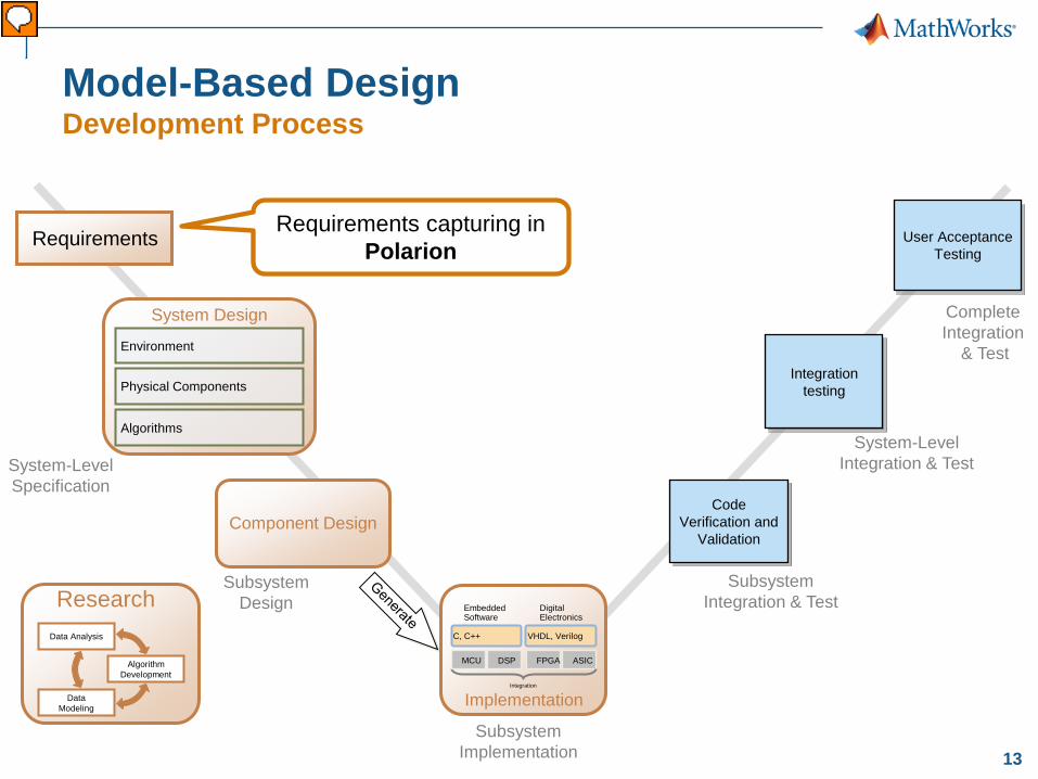
Model-Based Design Development Process
System-Level Specification
Subsystem Design
Subsystem Integration & Test
System-Level Integration & Test
Complete Integration
& Test
Code Verification and
Validation
Integration testing
User Acceptance Testing
Requirements Requirements capturing in
Polarion
Subsystem Implementation
DSP FPGA ASIC
Embedded Software
Digital Electronics
C, C++ VHDL, Verilog
Implementation Integration
MCU
Data Modeling
Algorithm Development
Data Analysis
Research
System Design
Physical Components
Environment
Algorithms
Component Design
Vorführender
Präsentationsnotizen
Betrachten wir die Schritte nun im Einzelnen: Ausgehend von den Anforderungen des Kunden, die zum Beispiel in Form eines Lastenheftes oder einer Kundenspezifikation vorliegen können, werden im Rahmen des Entwicklungsprozesses nun Anforderungen an das zu entwickelnde System abgeleitet. Dies erfolgt häufig in textueller Form und wird entweder zum Beispiel in Word oder auch Requirements-Management Tools, wie zum Beispiel Polarion durchgeführt. KLICK
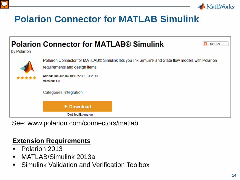
Um mit Requirements von Polarion nach Matlab Simulink zu verknüpfen, können Sie sich kostenlos den Polarion Connector von der Polarion-Website herunterladen und installierten. Sie brauchen dafür ein Polarion ab der Version 2013, ebenso ein Matlab/Simulink ab der Version 2013a Dazu ist die Simulink Validation and Verification Toolbox notwendig.
15
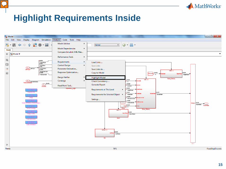
Highlight Requirements Inside
Vorführender
Präsentationsnotizen
Wenn Sie all das installiert haben, können Sie ihre Requirements mit dem Modell verknüpfen. Diese werden an Modellblöcke gebunden. Um zu sehen hinter welchen Modellblöcken sich requirements verbergen, können Sie sich das in Simulink anzeigen lassen. Wie hier gezeigt können Sie über das Menü den Punkt „Highlight Model“ auswählen und die requirements werden hervorgehoben. [click]
16
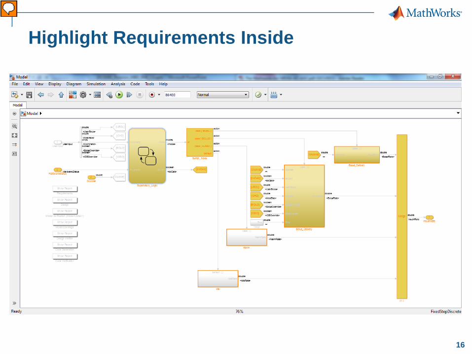
Highlight Requirements Inside
Vorführender
Präsentationsnotizen
Anschließend sehen Sie die Modellblöcke mit verlinkten Requirements farblich hervorgehoben.
17
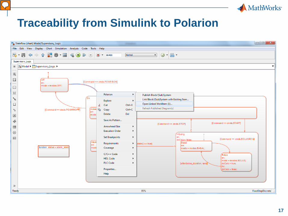
Traceability from Simulink to Polarion
Vorführender
Präsentationsnotizen
Egal wo Sie sich im Modell befinden, können Sie mit einem Rechtsklick auf das entsprechende Modellelement (das kann auch eine Transition in einem Statechart sein), die verlinkten Requirements einsehen.
18
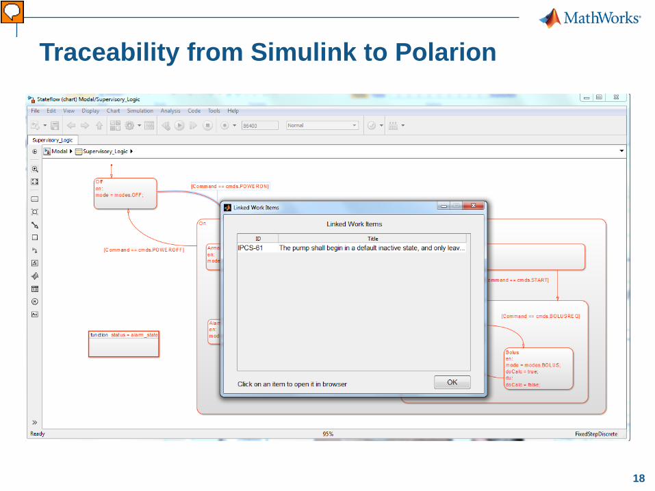
Traceability from Simulink to Polarion
Vorführender
Präsentationsnotizen
Das muss nicht nur eines sein, wie hier dargestellt, sonder können natürlich auch diverse Requirements mit dem Modellelement verknüpft sein. Hier ist es ein Requirement IPCS-61 (Insulin-Pump-Controller-System). Nun kann ich das Requirement auswählen und gelange über meinen Webbrowser auf das entsprechende Requirement in Polarion.
19
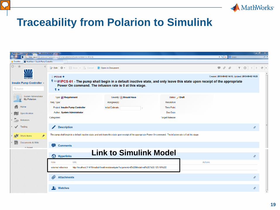
Traceability from Polarion to Simulink
Link to Simulink Model
Vorführender
Präsentationsnotizen
Sie sehen die Beschreibung der Anforderung … „The pump …“ und enprechende Attribute. Das war die eine Richtung der Verlinkung (namlich von Simulink nach Polarion). Anderst herum ist die Verlinkung ebenso möglich. [click] Im Requirement ist ein Link angegeben, der direkt zum Modell in Simulink führt.
20
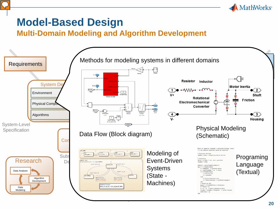
Model-Based Design Multi-Domain Modeling and Algorithm Development
System-Level Specification
Subsystem Design
Subsystem Implementation
Subsystem Integration & Test
System-Level Integration & Test
Complete Integration
& Test
Code Verification and
Validation
Integration testing
User Acceptance Testing
DSP FPGA ASIC
Embedded Software
Digital Electronics
C, C++ VHDL, Verilog
Implementation Integration
MCU
Requirements
System Design
Physical Components
Environment
Algorithms
Component Design
Data Modeling
Algorithm Development
Data Analysis
Research
Methods for modeling systems in different domains
Physical Modeling (Schematic) Data Flow (Block diagram)
Modeling of Event-Driven Systems (State - Machines)
Programing Language (Textual)
Vorführender
Präsentationsnotizen
Bei dem Entwicklungsprozess nach Model-Based Design, werden diese textuellen Requirements nun in Form von Modellen durch Verwendung von MATLAB/Simulink in eine Form gebracht, die eine eindeutige Umsetzung dieser Anforderung ermöglicht. Dadurch wird der Interpretationsspielraum stark eingegrenzt und eine eindeutige Beschreibung der Anforderung gewährleistet. In vielen Fällen wird schon hierdurch deutlich, ob Anforderungen genau genug spezifiziert sind und ob sie sich auch umsetzen lassen. Die Umsetzung dieser Anforderungen kann mit Hilfe der MW Tools auf verschiedene Weisen erfolgen. Zum einen durch einfache Simulink Diagramme, durch die physikalischen Modellierungsmöglichkeiten in SimScape oder aber durch textuelle Programmierung in MATLAB. Für Ereignisbasierte Systeme lässt sich eine Umsetzung durch Stateflow erreichen.
21
Data Modeling
Algorithm Development
Data Analysis
Research
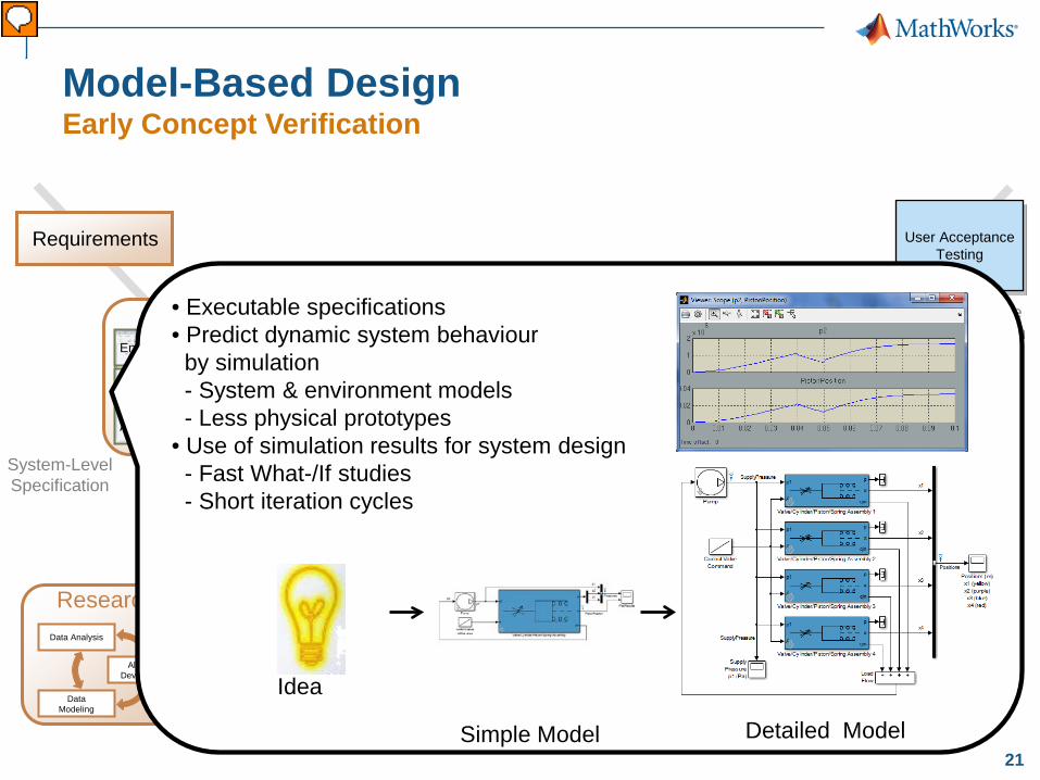
Model-Based Design Early Concept Verification
System-Level Specification
Subsystem Design
Subsystem Implementation
Subsystem Integration & Test
System-Level Integration & Test
Complete Integration
& Test
Code Verification and
Validation
Integration testing
User Acceptance Testing
DSP FPGA ASIC
Embedded Software
Digital Electronics
C, C++ VHDL, Verilog
Implementation Integration
MCU
System Design
Physical Components
Environment
Algorithms
Requirements
Component Design
• Executable specifications • Predict dynamic system behaviour by simulation - System & environment models - Less physical prototypes • Use of simulation results for system design - Fast What-/If studies - Short iteration cycles
Idea
Simple Model Detailed Model
Vorführender
Präsentationsnotizen
Durch die Umsetzung von Anforderungen in Modellform ist es möglich, eine ausführbare Spezifikation zu erhalten, die eindeutig ist. Des Weiteren erlaubt die Simulation eine Beurteilung des dynamischen Systemverhaltens, was dazu führt, dass weniger physikalische Prototypen gebaut werden müssen. Außerdem bietet die Simulation die Möglichkeit, schnell unterschiedlich Entwürfe auszuprobieren. Des Weiteren ist es möglich, den detaillierungsgrad von meinen Modellen immer weiter zu erhöhen und somit eine größere Realitätsnähe zu erreichen. Außerdem erlaubt diese Vorgehensweise zu beurteilen, welcher der Entwürfe für die Umsetzung der Anforderungen am Besten geeignet ist.
22
Data Modeling
Algorithm Development
Data Analysis
Research
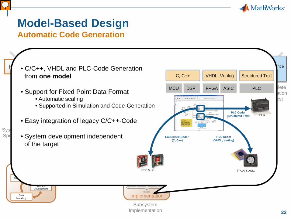
Model-Based Design Automatic Code Generation
System-Level Specification
Subsystem Design
Subsystem Integration & Test
System-Level Integration & Test
Complete Integration
& Test
Code Verification and
Validation
Integration testing
User Acceptance Testing
System Design
Physical Components
Environment
Algorithms
Requirements
Component Design
Subsystem Implementation
DSP FPGA ASIC
Embedded Software
Digital Electronics
C, C++ VHDL, Verilog
Implementation Integration
MCU
• C/C++, VHDL and PLC-Code Generation from one model
• Support for Fixed Point Data Format • Automatic scaling • Supported in Simulation and Code-Generation
• Easy integration of legacy C/C++-Code
• System development independent of the target
FPGA ASIC
VHDL, Verilog
DSP
C, C++
MCU
Embedded Coder (C, C++)
DSP & µC FPGA & ASIC
HDL Coder (VHDL, Verilog)
PLC PLC Coder
(Structured Text)
PLC
Structured Text
Vorführender
Präsentationsnotizen
Wir befinden uns jetzt also in der Implementierungsphase, als ganz unten im V-Modell. Die MathWorks Coder Tools bieten eine Vielzahl von Möglichkeiten zum Code-Erzeugung aus einem Simulationsmodell. Neben Standard Ansi ISO-C /C++ Code gibt es auch die Möglichkeit HDL Code und PLC Coder für Industriesteuerungen zu erzeugen. All das geht aus einem Modell. Durch die Erzeugung von Ansi ISO-C/C++ Code haben Sie die Möglichkeit zunächst unabhängig vom spezifischen Zielsystem zu entwickeln und nach Fertigstellung Ihrer Funktionalität diesen Ansi C-Code auf dem System zu integrieren.
23
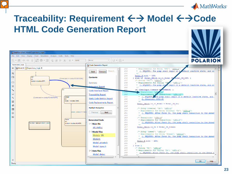
Traceability: Requirement Model Code HTML Code Generation Report
Vorführender
Präsentationsnotizen
Die eingangs angesprochene forward und backward Traceability zwischen Modell und Polarion-Requirement geht auch hier weiter. Ein Kommentar mit dem entsprechenden Requirement befindet sich im generierten Code (wenn Sie das wünschen). Damit wird eine durchgängige Traceability bis zum Code gewährleistet, wie es manche Standards fordern.
24
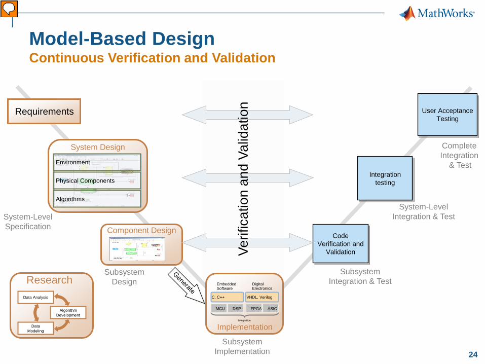
Model-Based Design Continuous Verification and Validation
System-Level Specification
Subsystem Design
Subsystem Integration & Test
System-Level Integration & Test
Complete Integration
& Test
Code Verification and
Validation
Integration testing
User Acceptance Testing
System Design
Physical Components
Environment
Algorithms
Requirements
Component Design
Verif
icat
ion
and
Valid
atio
n
Subsystem Implementation
DSP FPGA ASIC
Embedded Software
Digital Electronics
C, C++ VHDL, Verilog
Implementation Integration
MCU
Data Modeling
Algorithm Development
Data Analysis
Research
Vorführender
Präsentationsnotizen
Im Sinne von Model-Based Design und kontinuierlicher Verifikation und Validierung werden die GLEICHEN Testvektoren auch bei der Durchführung der Subsystem/Integrations Test und den Integrationstest auf Systemebene verwendet. Somit kann mit einer hohen Wahrscheinlichkeit sichergestellt werden, dass der Abnahme Test zeigt, dass die Anforderungen, welche zu Beginn des Projekts spezifiziert wurden, auch im Endprodukt umgesetzt worden sind.
25
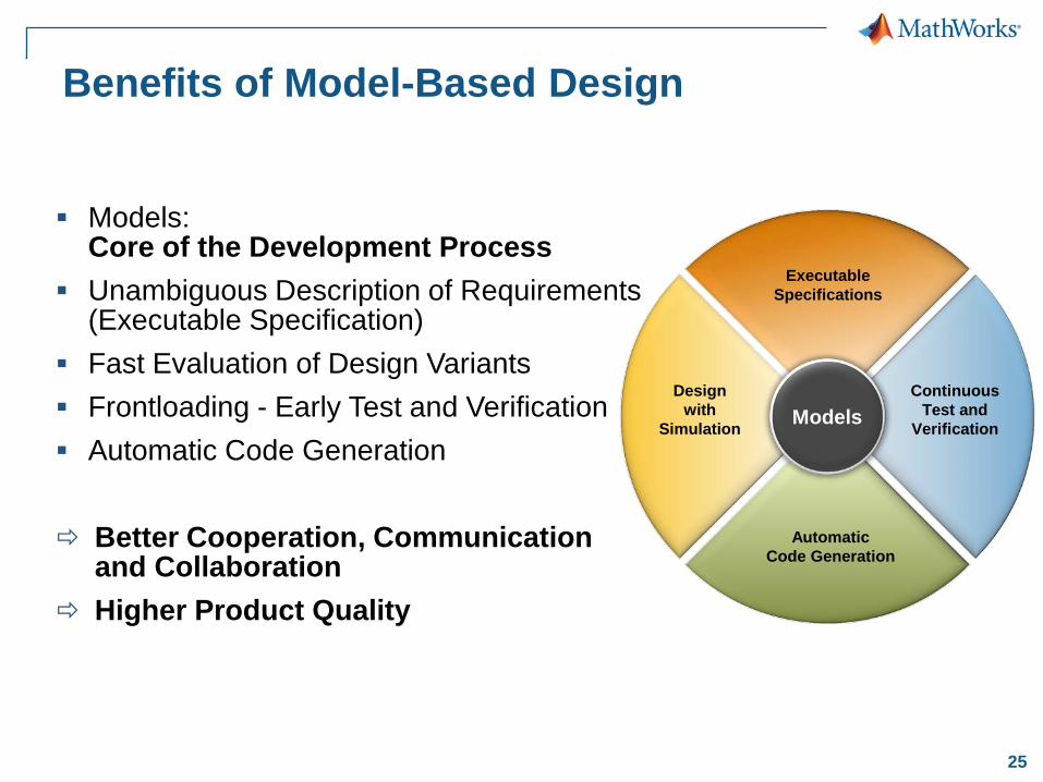
Benefits of Model-Based Design
Design with
Simulation
Executable Specifications
Continuous Test and
Verification
Automatic Code Generation
Models
Models: Core of the Development Process
Unambiguous Description of Requirements (Executable Specification)
Fast Evaluation of Design Variants Frontloading - Early Test and Verification Automatic Code Generation Better Cooperation, Communication