improving nuclear plant reliability by developing an eddy
TRANSCRIPT

1 Copyright © 2014 by ASME
IMPROVING NUCLEAR PLANT RELIABILITY BY DEVELOPING AN EDDY CURRENT TEST STRATEGY
TO IDENTIFY UNCOMMON CONDENSER TUBE DEFECTS
James A. Kocher Director of Emerging Technologies
Conco Services Corp. 530 Jones Street Verona, PA 15147
Robert Frazee System and Thermal Performance Engineer
STP Nuclear Operating Company PO Box 289, Wadsworth, TX 77483
Matthew Wolf Eddyfi
Senior Applications Specialist 2800 Louis-Lumière, Suite 100
Québec, Québec G1P 0A4 CANADA
ABSTRACT Eddy Current Testing (ECT) of condenser tubes is essential
to maintaining good plant reliability and availability. Early
identification of defects can allow for adequate remedial action
and prevent forced outages caused by condenser tube leaks.
The well-known catastrophic failure in the nuclear industry in
Japan has not only raised concern in Japan over aging nuclear
power plants, but has also raised concern over safe operations
in the United States and around the world. Ongoing reliability
and instability issues due to reported leaks in condensers have
also been the topic for nuclear watchdogs. This focus on the
nuclear plant condenser has brought to light the various levels
of sophistication and capability in ECT.
In ECT, the type of defect present in a condenser tube is
determined by the characteristics it presents under test. The
tubes must be adequately cleaned prior to testing and some
awareness or evidence of the type of defect to be uncovered
should be available to the testing team. In cases where defects
are discovered that are inconsistent with prior awareness further
exploratory testing is common. Exploratory testing can proceed
to test areas of suspected defects in the tubing, and it may result
in a complete redefinition of the test procedure, inclusive of
instruments, probe types and other key ECT criteria. A
comprehensive knowledge of testing options and their practical
application is necessary to redefine a test that will yield
meaningful results and achieve the intended objective; to
identify the type and extent of defect and take remedial action
therefore preventing failure.
This paper addresses such a case at the South Texas Project
(STP) Nuclear Power Plant where peculiar defects were
undeterminable under standard ECT procedures. The defects
continued to negatively impact reliability and stability at the
plant until a new ECT process and test procedure were
developed, demonstrated and deployed. The result achieved
was accurate defect detectability and improved nuclear plant
reliability.
INTRODUCTION With the catastrophe at Fukushima in Japan and a climate
of heightened concern over nuclear safety and reliability,
watchdogs have been holding nuclear power plants accountable
for providing adequate and frequent maintenance and inspection
programs to their plants to assure reliability. In the United
States, groups like the Citizen’s Awareness Network have asked
Proceedings of the ASME 2014 Power Conference POWER2014
July 28-31, 2014, Baltimore, Maryland, USA
POWER2014-32274

2 Copyright © 2014 by ASME
the Nuclear Regulatory Commission, or NRC, to investigate
plants like the FitzPatrick plant, of Entergy Nuclear Operations,
for untreated condenser problems. In the case of the FitzPatrick
plant, fouling and leaks dramatically decreased the efficiency
and reliability of the nuclear plant, which lead to instability,
catching the attention of nuclear watchdogs. (Citizens
Awareness Network, 2013) The detrimental long-term effects
of leaving the damage caused by fouling and leaks in
FitzPatrick’s condenser tubes’ unattended has been the source of
numerous avoidable unplanned outages and the sole reason that
Entergy has now completed a condenser replacement. (Alliance
for a Green Economy, 2013) Similarly, at the Vermont Yankee
nuclear power plant, nuclear watchdogs from the New England
Coalition wanted the plant closed as a result of wasteful
emissions as a result of condenser tube leakage. The untreated
leaks had allowed cooling water from the Connecticut River to
contaminate the condensate. Watchdogs know that a problem
like this could cause more inefficiency and unreliability through
secondary damages caused by foreign elements or objects
traveling in the steam. (Dillon, 2012)
Addressing the issue of condenser tube leaks and tube
condition is an important topic for a nuclear plant in achieving
reliability and stability in a climate where there is so much
concern. South Texas Project aims to keep their condenser
clean and reliable, maintaining availability long into the future.
Condenser Description
South Texas Project (STP) Nuclear Power Plant was
commissioned for operation in 1988. A picture of the plant is in
Figure 1. There are two units, Unit 1 and Unit 2, similar in
design and capacity. The condensers are single pass, multi-
stage with three compartments of 32,078 tubes each making the
total number of tubes per unit 96,234. The tube material is
titanium grade 2, size ¾” O.D. by 22 BWG approximately 54’
9’’ long. The units are base loaded and produce 1,250
megawatts of power each. Figure 2 shows the typical STP
waterbox.
Makeup water for the Circulating Water System is pumped
from the nearby Colorado River and sent to the facility’s 7,000
acre, 18 foot deep, holding reservoir adjacent to the plant. Two
traveling screen systems remove debris from the cooling water,
one for the water which is pumped from the river and the other
for the water from the reservoir to the condensers.
Eddy Current Testing
Eddy current testing is a well-established form of
nondestructive testing used to examine non-ferritic tubing in
condensers and heat exchangers. The eddy current method is a
volumetric testing process that uses an electromagnetic field to
identify defects in the tubing. An electron flow (eddy current)
is induced in electrically conductive material and an
electromagnetic field is generated. Any anomaly in the material
will disrupt the magnetic field or eddy current and the anomaly
can therefore be identified. Depending on the number of
frequencies and channels used, including both differential and
absolute channels, defects with unique characteristics such as
pitting, tube wall thinning, cracking, grooving or denting on the
inner diameter (ID), as well as the outer diameter (OD) of the
tubing can be found. The characteristics of the defects are often
the key to identifying the predominant failure or corrosion
mechanism present. The results are analyzed and anomalies can
be categorized and reported by defect type and depth. This
provides management with an accurate assessment of unit
condition and remaining useful life. Additionally, precautionary
steps can be taken to plug or avoid any potential failures
reducing costly condenser tube leaks and preventing forced
outages. (Droesch, D., et al.)
While Eddy Current testing is performed on non-ferritic
tubing material, ferritic materials are typically tested with
Remote Field Technology (RFT). Condenser and heat
exchanger tubing such as austenitic stainless steel, titanium,
brass and copper nickel are often tested with Eddy Current
methodology.
The applicable codes and procedures for performing Eddy
Current Testing for the balance of plant components at a nuclear
facility may include but are not limited to: the American Society
of Nondestructive Testing, Inc.’s (ASNT) SNT-TC-1A,
ANSI/ASNT CP 189 guidelines, ANSI E690 and E571, ASME
BPVC, Section V, Article 8 and ASNT Standard for
Qualification and Certification of Nondestructive Testing
Personnel.
PROJECT BACKGROUND
Condenser Tubes Heavily Scaled with Calcium Carbonate
In September, 2006, an inspection of the tubes in Unit 1 at
STP showed a scale deposit inside the tubes that proved on
analysis to be a very tenacious form of calcium carbonate, or
calcite (CaCO3). While tube fouling itself is detrimental to
plant performance and turbine backpressure, it usually consists
at STP as a result of varying degrees of particulate
sedimentation and biologic growth, from algae to bryozoa,
clams and mussels, the removal of which is not extraordinarily
difficult. Calcium carbonate scale, however, poses a serious
problem with limited remedial solutions. It is a crystalline
compound found in such materials as limestone and marble. At
STP, several tubes were tested for thickness of the CaCO3.
Thickness of twenty samples tested ranged from .007” to .031”,
with an average of .019”. It was concluded that the Unit 1
condenser performance was continuing to deteriorate due to the
increasing scale on the ID of the tubes and debris clogging the
tubes. STP Plan of Action was prepared.
The problem statement in STP’s Plan of Action cited that
scaling and fouling of the tubes resulted in degraded
performance of the condensers; the plan also noted that erosion
of the outlet tube sheets had been observed. Further, if these
processes were to continue there would be a serious operational
impact not only in performance but the continuing threat of
leaks could impact reliability and availability.
A comprehensive review of available technology for
removing calcium carbonate scale was conducted. It was

3 Copyright © 2014 by ASME
determined that the best cleaning procedure was going to be one
pass per tube with undersized standard metal-bladed cleaners,
followed by multiple passes of various sized calcium carbonate
cutting cleaners (incorporating scale cutting wheels) stepped in
seven sizes to satisfy a range of scale thickness. After the scale
had been fractured by the calcium carbonate cutting cleaners, a
final pass was made in each tube by the appropriately sized
standard all-purpose metal-bladed mechanical cleaner to
remove the fractured scale. The tube cleaners are shown in
Figure 3.
The initial cleaning project was successful and over 5,000
pounds of scale, was removed from the 96,234 condenser tubes
in Unit 1. In a subsequent outage, the Unit 2 condensers were
also cleaned with the same process used for Unit 1. Over 4
cubic yards of calcium carbonate, weighing more than 3,000
pounds, was removed from Unit 2. It is believed that the tubes
in Unit 2 were less fouled because they had been cleaned with
metal-bladed mechanical tube cleaners in a prior outage, while
the tubes in Unit 1 had been cleaned with nylon brushes that left
ridges inside the tubes, promoting faster build-up of debris and
scale.
The tube cleaning exercises were successful and as a result
of the removal of the calcium carbonate scale, South Texas
Project Nuclear Power Station reported a significant increase of
approximately 3 megawatts of power from the two units.
(Saxon, Jr. and Moye 2007)
The plant continued operation and performed regular
cleaning during overhauls during the next few refueling cycles.
Since the initial cleaning, the plant experienced improved
performance but had also experienced some condenser tube
leaks. The number and timing of leaks is shown as a graph in
Figure 4. The same information is listed in Table 1 below, Tube
Leaks.
Unit 1 Unit 2
No. Date When
Discovered No. Date
When
Discovered
3 Oct. –
06’ Outage 12
Feb. -
07’ Outage
3 Nov. –
06’ In Operation 1
Feb.
– 10’ In Operation
1 Sept. –
09’ In Operation 3
Apr. -
10 Outage
1 Dec. -
09’ In Operation 4
Mar.
– 12’ Outage
1 Oct. -
10’ In Operation 1
July
– 12’ In Operation
3 Mar. –
11’ Outage 1
June
– 13’ In Operation
2 Apr. -
11’ In Operation
1 June –
13’ In Operation
1 Aug. –
13’ In Operation
2 Sept. –
13’ In Operation
Table 1, Tube Leak Frequency
From October 2006 to September 2013 Units 1 and 2
experienced 18 and 22 tube leaks respectively, 25 of which
were discovered and adequately resolved during outages and 15
of which occurred during operating cycles over the seven year
period, for an average of approximately two leaks per year over
the two condensers. For the three year period from November
2006 to September 2009, the Unit 1 condenser operated
successfully without any leaks at all, as did Unit 2 from
February 2007 to February 2010. As indicated in Figure 4 there
were a number of causes for the tube leaks.
Concern about what appeared to be scratches and grooving
in the tubes was raised after the 2011 cleaning and outage. The
scratches and grooves were discovered during a boroscopic
examination conducted while examining a tube failure that had
occurred during the outage. Tubes were extracted, a root cause
investigation was initiated and a tube failure analysis
performed.
In discussion with plant personnel the primary concern was
through wall damage not seen in the sample provided, generated
from; a.) The force of operators pushing scale cutters that were
stuck in the tubes from deposit build up or obstructed tubes, and
b.) The grooves would give rise to fatigue cracking given the
vibration and stresses of operational cycles experienced at the
plant and in the condenser. For these reasons it was essential to
determine the extent and magnitude of the defects and access
the overall tube condition in the condensers. From sampling,
only a handful of tubes had been thoroughly inspected. To
mitigate the risk of additional tube failures, rather than only
testing the tubes known to have generated difficulty or have
blockages in the cleaning process, all 96,234 tubes in each
condenser were to be tested.
Tube samples were provided to a number of nondestructive
testing firms to develop a test plan. Figure 5 shows the tube
condition of one of the tube samples observed. The close up is
of the tube as found from the Inlet, 12N lower waterbox of the
unit 1 condenser, the area of interest in the particular tube
sample, the image shows some scratches and grooves
approximately ½” to 1” long. Figure 5 also shows an
unexpected observation of which appears to be a pit. The
following Figures 6 and 7 show the same defects at 15X and
60X magnification. In particular, Figure 7 shows three
markings that would typically all have a similar signal under a
traditional Eddy Current inspection, if any, yet the difference in
shape and size these markings would suggest different causes.
Figure 8, shows additional undefined irregularities on the tube
surface. Finally, Figure 9, is a cross section, a groove of
concern at 100X magnification, this groove being measured at
approximately 7% of tube wall loss is a channel and wide
groove of a much different radius than the tube ID and of a
different shape than any cleaning device would suggest. Other,
scratches on the internal surface were measured at 2% of tube
wall loss.
Given all of the above, there was motivation for a more
thorough investigation and modification of testing parameters.
4 Copyright © 2014 by ASME
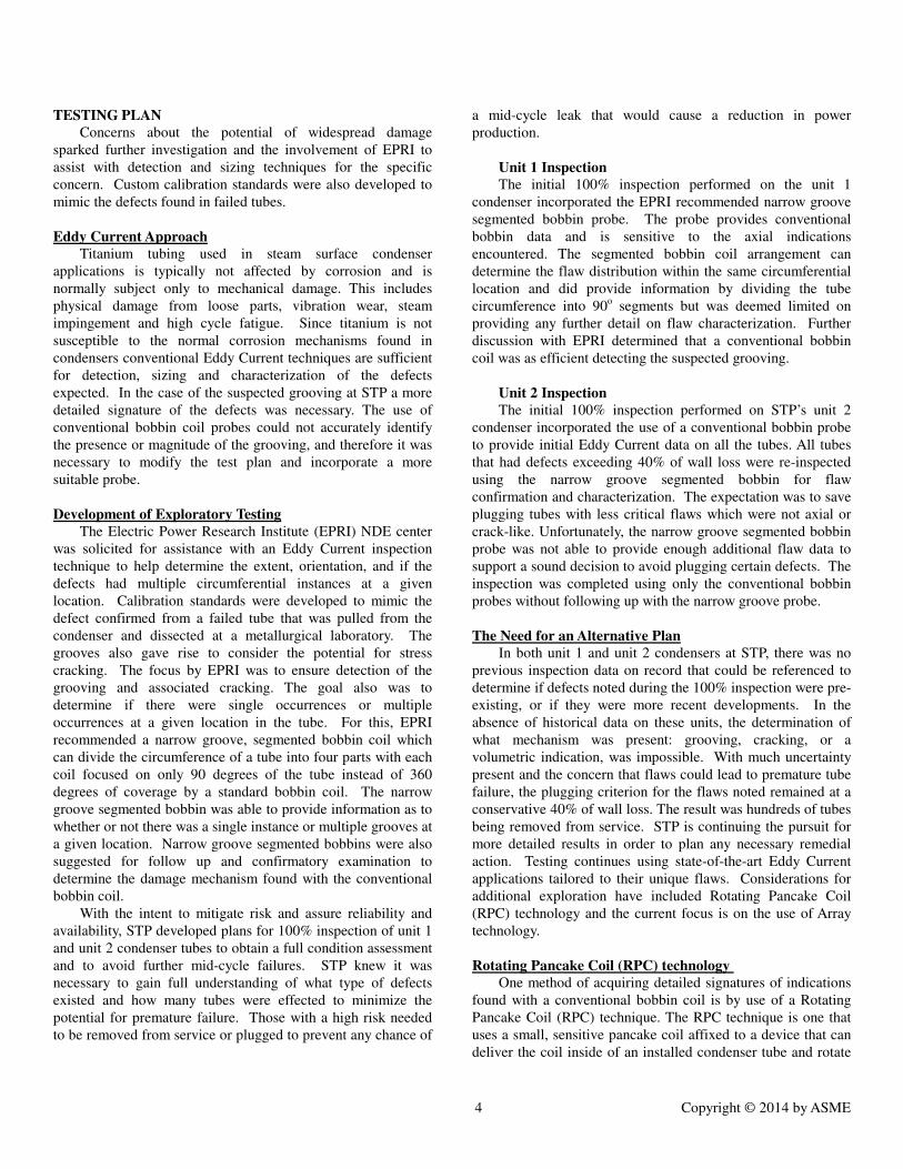
TESTING PLAN
Concerns about the potential of widespread damage
sparked further investigation and the involvement of EPRI to
assist with detection and sizing techniques for the specific
concern. Custom calibration standards were also developed to
mimic the defects found in failed tubes.
Eddy Current Approach
Titanium tubing used in steam surface condenser
applications is typically not affected by corrosion and is
normally subject only to mechanical damage. This includes
physical damage from loose parts, vibration wear, steam
impingement and high cycle fatigue. Since titanium is not
susceptible to the normal corrosion mechanisms found in
condensers conventional Eddy Current techniques are sufficient
for detection, sizing and characterization of the defects
expected. In the case of the suspected grooving at STP a more
detailed signature of the defects was necessary. The use of
conventional bobbin coil probes could not accurately identify
the presence or magnitude of the grooving, and therefore it was
necessary to modify the test plan and incorporate a more
suitable probe.
Development of Exploratory Testing
The Electric Power Research Institute (EPRI) NDE center
was solicited for assistance with an Eddy Current inspection
technique to help determine the extent, orientation, and if the
defects had multiple circumferential instances at a given
location. Calibration standards were developed to mimic the
defect confirmed from a failed tube that was pulled from the
condenser and dissected at a metallurgical laboratory. The
grooves also gave rise to consider the potential for stress
cracking. The focus by EPRI was to ensure detection of the
grooving and associated cracking. The goal also was to
determine if there were single occurrences or multiple
occurrences at a given location in the tube. For this, EPRI
recommended a narrow groove, segmented bobbin coil which
can divide the circumference of a tube into four parts with each
coil focused on only 90 degrees of the tube instead of 360
degrees of coverage by a standard bobbin coil. The narrow
groove segmented bobbin was able to provide information as to
whether or not there was a single instance or multiple grooves at
a given location. Narrow groove segmented bobbins were also
suggested for follow up and confirmatory examination to
determine the damage mechanism found with the conventional
bobbin coil.
With the intent to mitigate risk and assure reliability and
availability, STP developed plans for 100% inspection of unit 1
and unit 2 condenser tubes to obtain a full condition assessment
and to avoid further mid-cycle failures. STP knew it was
necessary to gain full understanding of what type of defects
existed and how many tubes were effected to minimize the
potential for premature failure. Those with a high risk needed
to be removed from service or plugged to prevent any chance of
a mid-cycle leak that would cause a reduction in power
production.
Unit 1 Inspection
The initial 100% inspection performed on the unit 1
condenser incorporated the EPRI recommended narrow groove
segmented bobbin probe. The probe provides conventional
bobbin data and is sensitive to the axial indications
encountered. The segmented bobbin coil arrangement can
determine the flaw distribution within the same circumferential
location and did provide information by dividing the tube
circumference into 90o segments but was deemed limited on
providing any further detail on flaw characterization. Further
discussion with EPRI determined that a conventional bobbin
coil was as efficient detecting the suspected grooving.
Unit 2 Inspection
The initial 100% inspection performed on STP’s unit 2
condenser incorporated the use of a conventional bobbin probe
to provide initial Eddy Current data on all the tubes. All tubes
that had defects exceeding 40% of wall loss were re-inspected
using the narrow groove segmented bobbin for flaw
confirmation and characterization. The expectation was to save
plugging tubes with less critical flaws which were not axial or
crack-like. Unfortunately, the narrow groove segmented bobbin
probe was not able to provide enough additional flaw data to
support a sound decision to avoid plugging certain defects. The
inspection was completed using only the conventional bobbin
probes without following up with the narrow groove probe.
The Need for an Alternative Plan
In both unit 1 and unit 2 condensers at STP, there was no
previous inspection data on record that could be referenced to
determine if defects noted during the 100% inspection were pre-
existing, or if they were more recent developments. In the
absence of historical data on these units, the determination of
what mechanism was present: grooving, cracking, or a
volumetric indication, was impossible. With much uncertainty
present and the concern that flaws could lead to premature tube
failure, the plugging criterion for the flaws noted remained at a
conservative 40% of wall loss. The result was hundreds of tubes
being removed from service. STP is continuing the pursuit for
more detailed results in order to plan any necessary remedial
action. Testing continues using state-of-the-art Eddy Current
applications tailored to their unique flaws. Considerations for
additional exploration have included Rotating Pancake Coil
(RPC) technology and the current focus is on the use of Array
technology.
Rotating Pancake Coil (RPC) technology
One method of acquiring detailed signatures of indications
found with a conventional bobbin coil is by use of a Rotating
Pancake Coil (RPC) technique. The RPC technique is one that
uses a small, sensitive pancake coil affixed to a device that can
deliver the coil inside of an installed condenser tube and rotate

5 Copyright © 2014 by ASME
the coil to scan the entire circumference of the tube ID.
Compared to a bobbin coil which interrogates the entire
circumference of a tube at the same time, the pancake coil is
smaller, more sensitive and can detect all types of degradation.
Though a pancake coil is capable of providing the level of
detail sought after, the technique has some undesirable traits.
The probes are fairly expensive and are somewhat delicate.
They normally do not perform well physically in environments
where the tube condition is not optimum and where spots of
scale and deposits may be present. Probe usage can be
excessive and costly. Additionally, the scanning speed is very
slow compared to a bobbin coil. The RPC probe traverses at
.2” to .5” per second compared to 36” to 60” per second with a
bobbin coil.
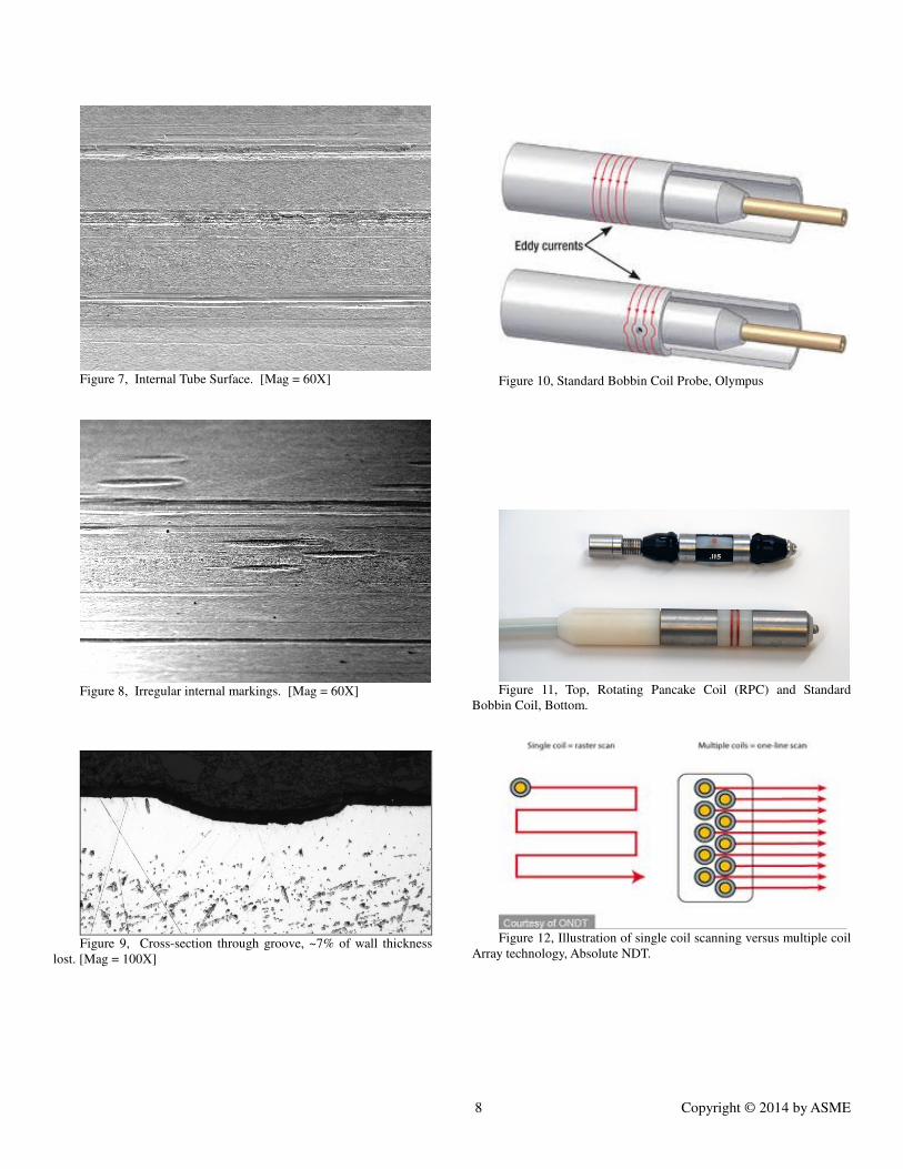
Figure 10 shows how a conventional bobbin coil
interrogates the entire tube circumference at the same time
limiting our ability to determine if a flaw is isolated or multiple
in a given instance. The RPC probe, Figure 11, can pinpoint
areas in the tube to provide more detailed flaw characteristics.
Array Technology
Array probes are the perfect blend of pancake coil
sensitivity with the convenience of full circumferential tube
coverage and a higher inspection speed. Much like the basic
pancake coil, Array coils are sensitive to all types of defects and
provide the same level of detail as the pancake and, in many
cases, even more detailed results. Coupled with an enhanced
digital display, the latest Array technologies provide
unsurpassed eddy current analysis.
Where the RPC technique is a single coil that has to be
rotated inside the tube to provide complete coverage, Array
techniques are an assembly of multiple pancake coils, as many
as 24 to 36, affixed to the probe body and can be pulled straight
through the tube without rotation. The illustration, Figure 12,
also shows the disadvantages of single coil scanning versus
multiple coil Array technology. The scanning speed using the
multiple array coils is much faster and insures complete
coverage. The real advantage can be seen in the display of the
data obtained from advanced Array coil technology (Figure 13).
The standard RPC display is a connection of scans
displayed on a grid to provide a view of the entire tube
circumference. Advanced Array coil displays connect the data
of each coil and displays it on a color gradient scan that is
voltage sensitive providing an easy to read image outlining the
defect’s signature. This once high cost technology, often out of
budget range for the balance of plant applications, has been
recently offered at a price that is affordable to the common
marketplace. For this particular Eddy Current inspection
application, the EddyFi DEFHI Array probe was selected for an
investigative inspection.
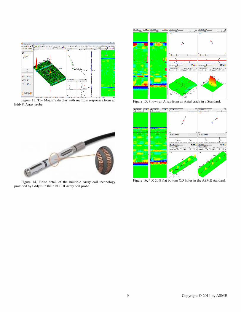
Figure 14, shows the finite detail of the multiple array coil
technology provided by EddyFi in their DEFHI Array coil
probe. The probe coupled with EddyFi’s Magnify software
allows for display of the data points seamlessly and shows
greater detail over the standard RPC technology.
In addition to the Array coils, the DEFHI probe
incorporates a conventional bobbin coil that provides for a
simultaneous standardized examination. The typical inspection
process requires a scan of the tubes with a bobbin coil followed
by a scan of the tube with a RPC or other specialized technique
to obtain information on defects of interest. This is an enormous
time savings, especially for tube inspections, where known
conditions exist that require the use of both techniques for
detection and sizing. Figure 15, shows an Array of an axial
crack in a calibration standard in the AXIAL F1 channel. The
Circumferential channel CIRC F1 has no response as expected,
it is only sensitive to circumferential damage.
Figure 16 shows 4 X 20% flat bottom OD holes in the
ASME standard. One can clearly see they are separated 90°
degrees apart and are volumetric since they are equally
responsive in both the CIRC and AXIAL channels.
When the STP samples were viewed with the EddyFi Array
technology the original assumption of the defects being caused
by the wheels of the scale cutters being forced through the tubes
may not have been correct due to the steep front and rear entry
and exit points of the defect. The defects if generated by the
wheels in the cleaning device would have shown a gradual entry
and exit to the flaw. Additionally, absent of the Eddy Fi
technology the unique defects in Figures 6 and 8 would have
appeared as a simple elongated groove under traditional Eddy
Current testing. In as much, EddyFi is leading to a more
thorough inspection and investigative result.
With the use of the Array technology, defects found in
condenser tubes can be further quantified into categories of
damage type, not just depth of wall loss. Various damage
mechanisms may require different plugging strategies. Tubes
with general pitting and volumetric flaws may be left in service
with deeper degradation than a crack-like indication. Having
more detailed defect characteristics can help avoid excessive
and sometimes unnecessary plugging. The EddyFi Array probe
was deployed on a trial basis to gather data from the STP
condenser tubes.
CONCLUSION
Eddy Current examination is used effectively for
determining defects in condenser tubing. However when the
defect characteristics are uncommon, variation in the testing
approach is necessary. In this case Eddy Current testing with
standard bobbin coil probes could not identify the unique
characteristics of the defects. Experimentation with narrow
groove probes and rotating pancake coil probes was required
before concluding that the most accurate testing results would
be achievable through application of Array technology.
Accuracy is essential for Eddy Current testing to be a viable
solution in risk mitigation and improving the reliability and
availability of the condensers in nuclear plants, keeping nuclear
watchdogs at bay as the nuclear power plants age. In the case
of STP a testing method has been developed and identified that
will help to assess the current condition and remaining useful

6 Copyright © 2014 by ASME
life of the condenser tubes. Following the assessment any
remedial action plan can be effectively implemented.
REFERENCES Alliance for a Green Economy. (2013, August 1). “FitzPatrick
Nuclear Reactor Sees Skyrocketing Condenser Problems”.
Alliance for a Green Economy. Retrieved January 27, 2014,
from
http://www.allianceforagreeneconomy.org/content/fitzpatrick-
nuclear-reactor-sees-skyrocketing-condenser-problems
Citizens Awareness Netowrk. (2013, March 18). “Watchdogs
say Entergy not qualified to operate reactors”. VTDigger.
Retrieved January 27, 2014, from
http://vtdigger.org/2013/03/21/watchdogs-say-entergy-not-
qualified-to-operate-reactors/
Dillon, J. (2012, April 11). VPR: “Condenser Leaks Plague
Vermont Yankee Plant.” Vermont Public Radio. Retrieved
January 27, 2014, from
http://www.vpr.net/news_detail/94113/condenser-leaks-plague-
vermont-yankee-plant/
Droesch, D., et al., (2006), “The Advantages of Using Multiple
Frequencies for Eddy Current Examination of Condenser
Tubing,” Proceedings of ASME Power 2006, Atlanta, GA, May
4-6, pg. 2
The American Society for Nondestructive Testing, Inc., (2007),
“Recommended Practice No. SNT-TC-1A 2006”, Columbus,
OH.
American Society of Mechanical Engineers, 2007, “ASME
Boiler and Pressure Vessel Code, Section V, Nondestructive
Examination, Article 8, Nondestructive Examination of Tubular
Products, NY, NY.
The American Society for Nondestructive Testing, Inc., (2007),
“ASNT Standard for Qualification and Certification of
Nondestructive Testing Personnel, 2006 Edition, Columbus,
OH.
Saxon, Jr., G. and Moye, W. (2007), “South Texas Nuclear
Power Plant Unit 1 Condenser; Scale Deposit Removal from
96,234 Condenser Tubes,” Proceedings of ASME Power 2007,
San Antonio, TX, July 17-19, pg. 3.
ACKNOWLEDGMENTS The authors acknowledge Conco Services Corp., STP
Nuclear Operating Company and Eddyfi for their support and
encouragement in producing this paper.
Figure 1, South Texas Project Nuclear Power Plant (STP)
Figure 2, One of Six Waterboxes of STP’s Unit 1 Condenser
Figure 3,Calcium Carbonate Tube Cleaner and Standard C4S
Type Tube Cleaner and CaCO3 Scale

7 Copyright © 2014 by ASME
Figure 4, Number and Timing of Condenser Tube leaks
Figure 5, Tube Interior Close-Up
Figure 6, Internal Surface. [Mag = 15X]
8 Copyright © 2014 by ASME
Figure 7, Internal Tube Surface. [Mag = 60X]
Figure 8, Irregular internal markings. [Mag = 60X]
Figure 9, Cross-section through groove, ~7% of wall thickness
lost. [Mag = 100X]
Figure 10, Standard Bobbin Coil Probe, Olympus
Figure 11, Top, Rotating Pancake Coil (RPC) and Standard
Bobbin Coil, Bottom.
Figure 12, Illustration of single coil scanning versus multiple coil
Array technology, Absolute NDT.
9 Copyright © 2014 by ASME
Figure 13, The Magnify display with multiple responses from an
EddyFi Array probe
Figure 14, Finite detail of the multiple Array coil technology
provided by EddyFi in their DEFHI Array coil probe.
Figure 15, Shows an Array from an Axial crack in a Standard.
Figure 16, 4 X 20% flat bottom OD holes in the ASME standard.