improving the performance of wind turbine equipped with dfig using statcom...
TRANSCRIPT

energyequipsys/ Vol 4/No1/June 2016/ 65-79
Energy Equipment and Systems
http://energyequipsys.ut.ac.ir www.energyeuquipsys.com
Improving the performance of wind turbine equipped with DFIG using STATCOM based on input-output feedback linearization controller
Authors
Ghazanfar Shahgholian a*
Noushaz Izadpanahi
a
a Islamic Azad University, Isfahan,
Iran
ABSTRACT Using the FACTS controllers, such as static synchronous compensator (STATCOM), as it provides continuous reactive power, in the grid including wind turbine (WT) equipped with doubly fed induction generator, for improving voltage profile (under normal circumstances) and providing a transition ability from inductor generator transition state has been proposed. In this paper, in order to control the controllers and explained goals, nonlinear controller, as a substitute for the traditional controller, is presented. Replacing STATCOM controller in wind farm, which is equipped with doubly fed induction generator (DFIG) using input-output feedback linearization controller, the needed reactive power in order to stable wind farm equipped with DFIG is considered when error is occurred. The proposed control method has been simulated for IEEE-9 Bus, bus No 5, and the achievability to the desired targets in STATCOM efficiency for its reactive power has been investigated. The reasons of using these controllers in bus 5 are voltage dropping and reducing reactive power in this bus. It can be seen by compensating for voltage and reactive power in this bus that these two parameters have improved in other buses. The results show that with the proposed controller, STATCOM has done its duty well and the network bus voltage and reactive power to sustain the wind farm equipped with DFIG in transient mode is provided.
Article history:
Received : 13 November 2015 Accepted : 9 January 2016
Keywords: Doubly Fed Induction Generator, Static Synchronous Compensator, Transition State, Wind Farm,
Input-Output Feedback Linearization Controller.
1. Introduction
Renewable energies for producing electrical power have been used since the environmental pollution, fossil fuel combustion, and the reduction of non-renewable fuels have become considerable. Among the existing renewable energies, the wind energy is considered to be a unique energy among other renewable energies, because it does not produce the greenhouse *Corresponding author: Ghazanfar Shahgholian Address: Najafabad Branch, Islamic Azad University, Najafabad, Isfahan, Iran E-mail address: [email protected]
gas and it is more useful, and has low maintenance costs [1-3]. Different kinds of both synchronous and asynchronous generators for utilizing the wind energy as a renewable and clean electromotive force have recently been employed [4-7]. Among various kinds of the used generators, doubly fed induction generator has the most application in wind turbine systems, because of variable speed performance, reduction of transducer power to 30% of generator power, loss and cost reduction, and the ability of controlling active and reactive power separately [8-9]. In normal state of working of doubly fed induction generator, the generator has the ability to operate in

66 Ghazanfar Shahgholian & Noushaz Izadpanahi /energyequipsys / Vol 4/No1/June 2016
variable speeds in the range of sub-synchronous to up-synchronous speeds. Since the stator in a doubly fed inductor generator is connected to the grid directly and the transducer power is limited, this generator is considerably sensitive to the grid disorders. Therefore, in the normal state of working and in spite of unbalance or voltage drop in the grid, the grid current will considerably be unbalanced or increased. This will cause heat in stator’s coils and also produce variations in power and torque with twice frequency of the grid which is harmful for the grid stability; it also corrupts the wind turbine mechanical system [1, 10].
In power grids, some problems, such as voltage drop or unbalanced voltage, occur most of the time. This kind of generator is also vulnerable in transition state. Because, when one of the short circuit errors occurs, an extreme voltage drop in generator terminal will be created. This voltage drop can cause extreme increase in the current of the rotors’ coils because the installed controllers on the generator have to control the power which is dictated to them. Therefore, when an extreme voltage drop occurs, for achieving the control purposes, an extreme increase in the rotors’ current will be suddenly caused [11-15]. Thus, there must be some solutions to protect the DFIG and also increase the reliability of the system.
In [16], in order to pass the transition state of doubly fed inductor generator, the use of series compensator has been proposed. In [17], a control method called “Fully Decoupled Feed-Forward” is used to pass the voltage drop of the doubly fed inductor generator. This way, direct power control (DPC) for a wind turbine equipped with DFIG and grid-side converter (GSC) has been used. Indeed, DPC for a wind turbine equipped with DFIG removes active power variations of stator and torque; and for GSC, it compensates active power variations of stator. To increase control performance on the overall system, resonance controllers in improved DPC have been considered to remove the torque and the ripple power which is caused by the unbalanced grid errors. The output power of the DFIG and GSC will be directly tunable without analyzing the positive and negative sequences.
In [18], using feed-forward transient current, the use of STATCOM as a reactive power compensator in point of common coupling (PCC) has been considered, so that it can keep the voltage stable, protect the DFIG
against system weak disorders before and after voltage shortage, and improve the power quality in a weak grid or un-symmetric load in transient state of the doubly fed inductor generator. Also, in [13-19], parallel FACTS devices, such as STATCOM[20], have been utilized in order to provide the reactive power for doubly fed inductor generator in transient state.
Many presented methods for protecting and controlling the inductor generator have utilized the PI controllers. These controllers are rather satisfying in industry; but they are not resistant. The coefficients for these types of controllers have been tuned for one state, considering the grid parameters, the equipment in the operating point and natural temperature. In transient states and natural temperature variations, the grid parameters will change and the tuned coefficients may no longer be exact and effective anymore. For this reason, PI controllers are not resistant against these variations.
In this paper, the use of parallel FACTS controller, such as STATCOM, for providing reactive power for doubly fed inductor generator under normal working circumstances and transient state has been proposed. Besides, in order to retrofitting and exact controlling the proposed system, input-output feedback linearization controller is used. Replacing STATCOM controller in wind farm which is equipped with doubly fed induction generator (DFIG) using input-output feedback linearization controller, the needed reactive power in order to stable wind farm equipped with DFIG is considered when error is occurred. In order to investigate and test the method, the proposed controllers, and to present the results, IEEE-9 Bus standard grid with a 2-megawatt wind farm has been simulated in MATLAB/Simulink [21]. 2. System Model To investigate the effect of the proposed control method, IEEE-9 Bus standard grid is considered for design, where the information of generators, lines, and loads have been presented in [22]. The equations of generators (2) and (3) are fully simulated and because the size of the network is relatively large and requires to quick resolution of network equations and obtaining results such as voltage, current, active and reactive power, etc., the network equations can be solved using the Runge-Kutta method.

Ghazanfar Shahgholian & Noushaz Izadpanahi /energyequipsys / Vol 4/No1/June 2016 67
2.1. Modeling of the Wind Farm Equipped with DFIG
Figure 1 shows the overall scheme of a doubly fed inductor generator, while it is connected to the grid. To calculate the mathematical model of the doubly fed inductor generator, the following assumptions must be considered [23]: Active and reactive powers are positive,
when they are going toward generator. The equations have been chosen from
synchronous grid reference system. The q-axis is leaded from d-axis by 90
degree. Equations for inductor generator voltage in synchronous grid reference system are given as [24].
sdqb
ssdq
bsdqssdq j
dt
diRv
1
(1)
rdqb
rsrdq
brdqrrdq j
dt
diRv
)(1 ,
(2)
where and represent stator voltage vector and rotor voltage vector, respectively.
and represent stator and rotor
magnetic flux vector, respectively. s and b stand for the speed of synchronous reference system and the speed of Pu reference, respectively. Rs and Rr represent stator and rotor coils resistant, respectively. The equations for stator and rotor’s flux are expressed as
rdqmsdqssdq iXiX
(3)
sdqmsdqrrdq iXiX
(4)
From (3), we have
,)(1
rdqmsdq
s
rdq iXx
i
(5)
where, Xs, Xr, and Xm stand for stator reactance, rotor reactance, and magnetizing reactance, respectively. Substituting (5) in (4), one gets
,rdqsdq
s
m
rdq ix
x
(6)
where
.)(2
s
m
rx
xX
(7)
To design an input-output feedback linearization controller for DFIG, the tracking purposes should be defined first. In designing such controller, we are looking for controlling and tracking the stator-side active and reactive power (Qs and Ps) in RSC. In GSC, we are looking for controlling the DC link voltage and the transferred reactive power from the grid (Qg and Vdc). The next step is to differentiate the desired equations until the control input appears, and then calculate the desired control input. Substituting Eq.(6) in Eq.(2), rotor voltage to stator flux and rotor current will be given, where the differentiated rotor current is obtained from. The controller in RSC and GSC will be designed in accordance with the defined targets, explained earlier.
In designing input-output feedback linearization controller for RSC, we are looking for controlling and tracking the stator-side active and reactive power. In (8) and (9), the equations for stator-side active and reactive power are given by
)(2
3sqsdsdsqs ivivQ
(8)
.)(2
3sqsqsdsds ivivP
(9)
As it can be seen, the above equations are indirectly related to the control input (Vrd and Vr). Therefore, differentiating these two equations can be the first step to find the input. It is also worth mentioning that, since all the equations presented for DFIG are in
Fig. 1. The wind turbine equipped with doubly fed induction generator scheme

68 Ghazanfar Shahgholian & Noushaz Izadpanahi /energyequipsys / Vol 4/No1/June 2016
synchronous grid system, the vertical component of voltage is zero and the horizontal component is a constant. The d and q components of rotor voltage are the control inputs in above equations for RSC; thus, they should be appropriately selected, so that the tracking will be well performed. In other words, control inputs should be selected in a way that: Remove the non-linear components in (8)
and (9). Apply a linear dynamic in a way that,
after the non-linear components are removed, the system remains in a good time behavior.
Therefore, according to the two mentioned points, the control inputs can be selected as [25]
)(3
211 Fv
V
LV
sd
mrd
(10)
,)(3
222 Fv
V
LV
sd
m
rq
(11)
where, v1 and v2 can be expressed as
dtekekPv
ss ppsref 211
(12)
srefsP PPes
(13)
dtekekQvss QQsref 432
(14)
srefsQ QQes
(15)
and F1 and F2 are given as
)iRV(
L
LiR
L
VF sq
b
esdssd
m
rrq
b
rerdr
m
ds
2
31
(16)
.)(2
32
sd
b
esds
m
rrd
b
rerqr
m
ds iRL
LiR
L
VF
(17)
The values of the control parameters K1, K2, K3, and K4 are obtained through trial and error method. The control diagram of RSC of DFIG is shown in Fig.2. The functionality of the principle will be the same as the previous
(a) The control diagram of Vrd,
(b) The control diagram of Vrq
(c) The control diagram of I_RSC
Fig. 2. The control diagram of RSC

Ghazanfar Shahgholian & Noushaz Izadpanahi /energyequipsys / Vol 4/No1/June 2016 69
section. The equations for control targets (Pg and Qg) will be re-written and be differentiated, so that the control inputs in the equations appear [20]. At last, based on feedback linearization strategy, the control inputs will be designed. That is
)(3
211 FFvv
V
LU
sd
ggd
(18)
,)(3
222 FFvv
V
LU
sd
g
gq
(19)
where vv1 and vv2 will be considered to be as
dtekekPvvgg ppgref
651 (20)
grefgp PPeg
(21)
dtekekQvvgg QQgref
872 (22)
,grefgQ QQeg
(23)
and FF1 and FF2 are given as
)(2
31 gdgsd
g
sd iRVL
VFF
(24)
.)(2
32 gqg
g
sd iRL
VFF
(25)
The values of the control parameters K5, K6, K7, and K8 are obtained through trial and error method. The control diagram of GSC of DFIG is shown in Fig.3. The following will discuss how to calculate the appropriate control inputs for STATCOM.
2.2. STATCOM Mathematical Equations As it was mentioned earlier, in this paper, the aim of using STATCOM is to improve the wind turbine equipped with doubly fed inductor generator (DFIG) in normal and transient state. Therefore, an appropriate electrical model for this controller is presented. The desired electrical model for STATCOM is shown in Fig.4. Based on the model, mathematical equations for that will be defined, and the design will be performed by the equations. According to Fig.2, the current-voltage equations in synchronous reference system, between internal bus and the bus connected to the grid are given as [26]
Pccdsd
cd Vdt
dILV
(26)
,Pccq
sq
cq Vdt
dILV
(27)
(a) The control diagram of Ugd
(b) The control diagram of Ugq
(c) The control diagram of I_GSC
Fig. 3. The control diagram of GSC

70 Ghazanfar Shahgholian & Noushaz Izadpanahi /energyequipsys / Vol 4/No1/June 2016
where Vcd and Vcq is the real and imaginary part of the internal voltage, Vpccd and Vpccq is the real and imaginary part of the STATCOM connection bus to the grid voltage, Isd and Isq is the real and imaginary part of the STATCOM injected current to the grid, respectively. L is the equivalent inductance. The equations for active and reactive power in STATCOM to grid connection bus are given as
sqpccqsdpccdpcc IVIVP (28)
and
,sqpccdsdpccqpcc IVIVQ (29)
where Ppcc and Qpcc is the injected active and reactive power to the grid, respectively. Based on the Eqs. (26) to (29), we can design the desired controller. As it was mentioned earlier, in this paper, input-output feedback linearization controller has been utilized. The conventional controllers, such as PI, confront the designers with a few problems; for example, the designers have to tune the coefficients constantly. Also, these controllers are not strong enough to be stable when the situations for grid and STATCOM change. When designing these types of controllers, firstly, the output equations of the system should be written for the input and the state variables. In these equations, if the control inputs are not visible, we will differentiate the equations until the control inputs appear. The Eqs. (26) to (29) have been in synchronous reference system (the vertical component is zero and the horizontal component is a constant). Therefore, one will have
sdpccdpcc IVP
(30)
.sqpccdpcc IVQ
(31)
Since, in STATCOM controller, the aim is to inject active power; therefore, reference active power for input-output feedback linearization control strategy is considered to be zero.
Reactive reference power in this strategy, based on the diagram shown in Fig.5, is applied to the control system.
According to the context of what we already said, the following equations, the input controllers based on this controller’s strategy are given as
)( pp
pccd
cd FvV
LV
(32)
pccd
cq FvV
LV
(33)
where in (32) and (33)
dtekekPv pppprefp 21
(34)
refp PPe (35)
dtekekQv QQQQrefQ 21
(36)
.refQ QQe (37)
The values of the control parameters Kp1, Kp2, KQ1, and KQ2 are obtained through trial and error method. The control diagram of STATCOM is shown in Fig.6.
As we can see, the input controllers for
Fig. 4. Electrical model for STATCOM
PI ControllerΣ
V
|Vref| Qref
+
-
Fig. 5. Block diagram of the defining process for reference reactive power, aiming to control the voltage for STATCOM to grid connection bus

Ghazanfar Shahgholian & Noushaz Izadpanahi /energyequipsys / Vol 4/No1/June 2016 71
(a) The control diagram of Vcd
(b) The control diagram of Vcq
(c) The control diagram of I_STATCOM
Fig. 6. The control diagram of STATCOM
STATCOM have been designed using input-output feedback linearization controller, where by applying these inputs to the desired system (STATCOM equations), the desired results can be observed. According to calculated equations in this section and the presented input-output feedback linearization controller method in [21, 24], the proposed controller can be implemented.
3. Simulation results
As mentioned, in this paper, the use of non-linear controllers for an exact, fast, and robust control of the FACTS controllers such as static synchronous compensator (STATCOM), as provides continuous reactive power, in the grid including wind farm equipped with doubly fed induction generator, for improving voltage profile and providing a transition ability from inductor generator transition state has been proposed. Replacing STATCOM controller in a wind farm, which is equipped with doubly fed induction generator (DFIG) using input-output feedback linearization controller, the
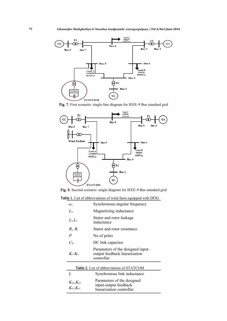
needed reactive power in order to stable wind farm equipped with DFIG is considered when error is occurred. For STATCOM in the domain of reactive power on the studied grid, two scenarios are considered: (a) considering the effect of STATCOM on improving IEEE-9 Bus standard grid voltage profile shown in Fig.7 and (b) considering the effect of STATCOM on improving the performance of wind farm equipped with DFIG, while short circuit error on the line occurs (as between bus number 5 and bus number 7) shown in Fig.8.
Single-line diagram for the studied grid is as Figs. 7 and 8. According to what we already said, we can simulate the studied grid, the wind turbine, and STATCOM. In primary condition and, also in the first and second scenarios, the grid can be analyzed, and the desired results can be provided. The employed parameters of this paper are listed in Tables 1, 2, and 3. The information of Transmission lines, generators, and local loads are given by [21].
72 Ghazanfar Shahgholian & Noushaz Izadpanahi /energyequipsys / Vol 4/No1/June 2016
Fig. 7. First scenario: single-line diagram for IEEE-9 Bus standard grid
Fig. 8. Second scenario: single diagram for IEEE-9 Bus standard grid
Table 1. List of abbreviations of wind farm equipped with DFIG
Synchronous angular frequency ωs
Magnetizing inductance Lm
Stator and rotor leakage inductance Lls,Llr
Stator and rotor resistance Rr, Rs
No of poles P
DC link capacitor Cds
Parameters of the designed input-output feedback linearization controller
K1-K9
Table 2. List of abbreviations of STATCOM
Synchronous link inductance L
Parameters of the designed input-output feedback linearization controller
KQ1,KQ2 KP1,KP2

Ghazanfar Shahgholian & Noushaz Izadpanahi /energyequipsys / Vol 4/No1/June 2016 73
Table 3. Employed system parameters
System Bases
Vbase=690v, Sbase=2MW, ωbase=2πfbase fbase=60Hz
DFIG
P=2, ωs=ωe=ωb, ωr=80π, Nsr=0.333, Lm=2.5×10⁻³ ,Lls=77.306×10⁻⁶
Llr=83.369×10⁻⁶ ,Rr=2.9×10⁻³ ,Rs=2.5×10⁻³
Cdc=16×10-6, K1=1000, K2=10000, K3=K4=1000000
K5= K6=10000, K7=10000000, K8=10, K9=1
STATCOM
Rst=0, L=0.25×10⁻³, KP1=1000, KP2=100, KQ3=1000, KQ4=100
Therefore, in order to investigate and
understand the effect of equipment such as STATCOM and wind farm on each other and grid parameters, which will be considered in the next sections, the voltage profile results and the power passed through the lines, which is simulated in IEEE-9 Bus standard grid without having the equipment, is shown in Figs. 9, 10, and 11. As it is seen in Fig.9,
voltage level for bus (5) has the minimum level of voltage in the grid. Therefore, in the first scenario, STATCOM will be placed on this bus. It can be seen by compensating for voltage and reactive power in this bus that these two parameters have improved in other buses. In Figs. 10 and 11, transferred power for lines is shown, where the amount of the transferred power in each line depends on bus’s voltage level.
Fig. 9. Bar diagram for bus’s voltage profile in primary condition (before considering the scenarios) based on bus number
Fig. 10. Bar diagram for transferred active power based on lines number
0.9
0.92
0.94
0.96
0.98
1
1.02
1.04
Bus 1 Bus 2 Bus 3 Bus 4 Bus 5 Bus 6 Bus 7 Bus 8 Bus 9
Vo
lta
ge P
ro
file
(p
u)
Bus Number
0
0.2
0.4
0.6
0.8
1
1.2
1.4
1.6
1.8
2
Line
1-4
Line
4-5
Line
4-6
Line
5-7
Line
6-9
Line
2-7
Line
3-9
Line
7-8
Line
8-9
Act
ive
Po
wer
(p
u)

74 Ghazanfar Shahgholian & Noushaz Izadpanahi /energyequipsys / Vol 4/No1/June 2016
Fig. 11. Bar diagram for transferred reactive power based on lines number
3.1. First Scenario
As we can conclude in Fig.9, in first scenario, in order to investigate the effect of STATCOM on improving the voltage profile of the studied grid, the equipment is placed on bus (5) where the single-line diagram of the grid is seen in Fig.7. The results from STATCOM to grid (IEEE-9 Bus standard grid) connection in bus (5) are shown in Figs. 12 and 13. As it is seen in
Fig.12, after connecting the STATCOM on the bus (5), the voltage for the bus will be the desired amount; 1.02. The voltages for all the PQ buses will also be improved. Moreover, according to Fig.13, the transferred power of lines is increased in this state, i.e. the lines capacity is freer compared to the primary conditions. These results show that, in this state, the selected control strategy for the desired equipment has performed its duties as well.
Fig. 12. Bar diagram for bus’s voltage profile vs. bus number in first scenario
Fig. 13. Bar diagram for transferred active power in lines vs. lines number in first scenario
0
0.1
0.2
0.3
0.4
0.5
0.6
Line
1-4
Line
4-5
Line
4-6
Line
5-7
Line
6-9
Line
2-7
Line
3-9
Line
7-8
Line
8-9
Rea
cti
ve P
ow
er (
pu
)
0.9
0.92
0.94
0.96
0.98
1
1.02
1.04
1.06
Bus 1 Bus 2 Bus 3 Bus 4 Bus 5 Bus 6 Bus 7 Bus 8 Bus 9
Vo
lta
ge P
ro
file
(p
u)
Bus Number
With STATCOM (IOFC) Without STATCOM
00.20.40.60.8
11.21.41.61.8
2
Line
1-4
Line
4-5
Line
4-6
Line
5-7
Line
6-9
Line
7-8
Line
9-8
Line
3-9
Line
2-7
Acti
ve P
ow
er (
pu
)
With STATCOM (IOFC) Without STATCOM
Ghazanfar Shahgholian & Noushaz Izadpanahi /energyequipsys / Vol 4/No1/June 2016 75
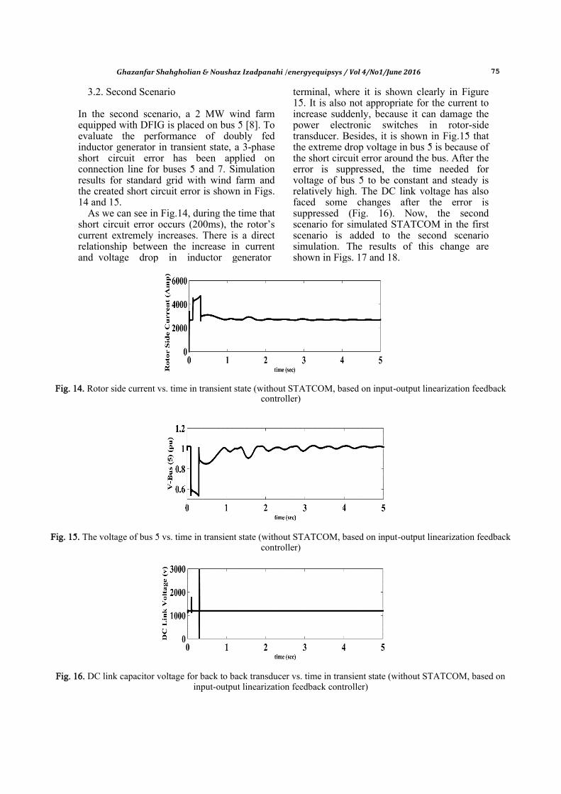
3.2. Second Scenario In the second scenario, a 2 MW wind farm equipped with DFIG is placed on bus 5 [8]. To evaluate the performance of doubly fed inductor generator in transient state, a 3-phase short circuit error has been applied on connection line for buses 5 and 7. Simulation results for standard grid with wind farm and the created short circuit error is shown in Figs. 14 and 15.
As we can see in Fig.14, during the time that short circuit error occurs (200ms), the rotor’s current extremely increases. There is a direct relationship between the increase in current and voltage drop in inductor generator
terminal, where it is shown clearly in Figure 15. It is also not appropriate for the current to increase suddenly, because it can damage the power electronic switches in rotor-side transducer. Besides, it is shown in Fig.15 that the extreme drop voltage in bus 5 is because of the short circuit error around the bus. After the error is suppressed, the time needed for voltage of bus 5 to be constant and steady is relatively high. The DC link voltage has also faced some changes after the error is suppressed (Fig. 16). Now, the second scenario for simulated STATCOM in the first scenario is added to the second scenario simulation. The results of this change are shown in Figs. 17 and 18.
Fig. 14. Rotor side current vs. time in transient state (without STATCOM, based on input-output linearization feedback
controller)
Fig. 15. The voltage of bus 5 vs. time in transient state (without STATCOM, based on input-output linearization feedback
controller)
Fig. 16. DC link capacitor voltage for back to back transducer vs. time in transient state (without STATCOM, based on
input-output linearization feedback controller)

76 Ghazanfar Shahgholian & Noushaz Izadpanahi /energyequipsys / Vol 4/No1/June 2016
Fig. 17. The voltage for bus 5 vs. time in transient state (with STATCOM, based on input-output linearization feedback
controller)
As it is observed in Fig.18, injecting required reactive power using STATCOM (in both types of controllers) does not let the current of rotors coils increases. Also in this case, the change in rotor’s current directly depends on the increase in voltage of bus 5, which is depicted in Fig.17. As we can see in Fig.17, since the STATCOM is added to the system (in both control methods), the voltage profile for bus 5 is improved. In this case, the voltage level is improved and recovered. Moreover, the voltage variations disappear very fast; because the reactive power is being injected to the grid at that time. The robustness of non-linear controllers has always been an important concern which needs to be considered here.
As we have seen from the results presented here, the nonlinear controllers used for
STATCOM is robust enough in transient state (one of the un-definitions of the system); and the defined targets (improving the voltage level) for STATCOM have been well done. Although, sometimes the un-definitions appear in system parameters which will change according to some reasons such as heat. In this paper, it is assumed that there are 20% un-definitions in bus 4 and 5 admittance. Therefore, shown in Figs. 19 and 20, the results of the input-output linearization feedback controller and the PI controller have been compared. According to Figs. 19 and 20, we can see that by creating parametric changes (un-definitions) the PI controller cannot provide the desired results with the same coefficients; whereas, the parametric un-definitions do not have effect on the performance of the input-output linearization feedback controller.
(a) Without STATCOM
(b) With STATCOM based on input-output linearization feedback controller Fig. 18. Rotor side current vs. time in transient state

Ghazanfar Shahgholian & Noushaz Izadpanahi /energyequipsys / Vol 4/No1/June 2016 77
(a) Without STATCOM
(b) With STATCOM based on PI controller
(c) With STATCOM based on input-output linearization feedback controller Fig. 19. Rotor side current vs. time in transient state, with 20% un-definitions
(a) With STATCOM based on PI controller
(b) With STATCOM based on input-output linearization feedback controller
Fig. 20. Voltage for bus 5 in transient state vs. time 20% un-definitions

78 Ghazanfar Shahgholian & Noushaz Izadpanahi /energyequipsys / Vol 4/No1/June 2016
4. Conclusion In this paper, we have proposed and investigated input-output linearization feedback controller as an appropriate controller (in case of implementation and tracing the desired targets) and robust, in order to control STATCOM for providing reactive power and the desired services in this field, for improving various parameters such as voltage, active power movement, improving the DFIG equipped wind farm error, etc. in order to evaluate the quality of the proposed method, IEEE-9 Bus standard grid, as a test grid, has been utilized. The simulation results show that the use of this type of controller for utilizing parallel FACTS controller such as STATCOM in the field of reactive power causes the grid voltage profile to improve in normal state of working. As a result, the loss reduces and the lines capacity will be achievable. This also keeps the doubly fed inductor generator voltage terminal in a desired situation in transient state, so that the wind farm will not stop working. The results also show that the parametric change in the grid does not affect the STATCOM performance; whereas, the conventional controller which utilizes PI, when the grid topology changes, it needs to tune the parameters again and again. The simulation results for the proposed controller not to need to tune the parameters and to have a desired response when the grid topology changes. This shows that the proposed control method is robust enough. References [1] Shang L., Hu J., Sliding-Mode-Based Dir-
ect Power Control of Grid-Connected Wind -Turbine-Driven Doubly Fed Induct-ion Generators Under Unbalanced Grid Voltage Conditions, IEEE Trans. on Energy Conversion (2012) 27: 362–373.
[2] Fooladgar M., Rok-Rok E., Fani B., Sha-hgholian Gh., Evaluation of the Trajectory Sensitivity Analysis of the DFIG Control Parameters in Response to Changes in Wind Speed and the Line Impedance Connection to the Grid DFIG, Journal of Intelligent Procedures in Electrical Techn-ology (2015) 5: 37-54.
[3] Mahdavian M., Wattanapongsakorn N., Shahgholian Gh., Mozafarpoor S.H., Janghorbani M., Shariatmadar S.M., Max-imum Power Point Tracking in Wind Energy Conversion Systems Using Tracking Control System Based on Fuzzy
Controller, IEEE/ECTICON (2014) May, 1-5.
[4] Baroudi J.A., Dinavahi V., Knight A.M., A Review of Power Converter Topologies for Wind Generators, IEEE/IEMDC, (2005) May 458-465
[5] Shukla R.D., Tripathi R.K., Gupta S., Power Electronics Applications in Wind Energy Conversion System: A Review, IEEE/ICPCES (2010) Dec.1-6.
[6] Kim H.S., Lu D.D.-C., Review on Wind Turbine Generators and Power Electronic Converters with the Grid-Connection Iss-ues, IEEE/AUPEC (2010) Dec.1-6.
[7] Shahgholian Gh., Khani Kh., Moazzami, M., The Impact of DFIG Based Wind Turbines in Power System Load Frequency Control With Hydro Turbine, Dam and Hedroelectric Powerplant (2015) 1: 38-51.
[8] Zhe Chen J.M., Guerrero F., Blaabjerg, A Review of the State of the Art of Power Electronics for Wind Turbines, IEEE Trans, on Power Electronics (2009) 1859-1875.
[9] Muller S., Deicke M., De-Doncker R.W., Doubly Fed Induction Generator Systems for Wind Turbines, IEEE Industry Appl-ications Magazine (2002) 8: 26-33.
[10] Santos-Martin D., Rodriguez-Amenedo J.L, Arnalte S., Direct Power Control Applied to Doubly Fed Induction Generator Under Unbalanced Grid Voltage Conditions, IEEE Trans. on Power Electronics (2008) 23: 2328-2336.
[11] Qiao W., Harley R.G., Venayagamoorthy G.K., Real-Time Implementation of a STATCOM on A Wind Farm Equipped With Doubly Fed Induction Generators, IEEE Trans. on Industry Applications (2009) 45: 98-107.
[12] Morren J., De-Haan S.W.H., Ride-Throu-gh of Wind Turbines With Doubly-Fed Induction Generator During A Voltage Dip, IEEE Trans. on Energy Conversion (2005) 20: 435-441.
[13] Muljadi E., Butterfield C.P., Chacon J., Romanowitz H., Power Quality Aspects in A Wind Power Plant, IEEE/PESGM (2006) 1-8.
[14] Yi T., Guangwei Y., Research on Impacts of Grid Voltage Sag on Wind Power Sys-tem Reliability, IEEE/APPEEC (2012) March 1-5.
[15] Liu J., Liang H., Li W., Guo R., Research on Low Voltage Ride Through Capability of Wind Farms Grid Integration Using VSC-HVDC, IEEE/ISGT (2012) May 1-6.

Ghazanfar Shahgholian & Noushaz Izadpanahi /energyequipsys / Vol 4/No1/June 2016 79
[16] Abdel-Baqi O., Nasiri A., Series Voltage Compensation for DFIG Wind Turbine Low-Voltage Ride-Through Solution, IEEE Trans. on Energy Conversion (2011) 26: 272-280.
[17] Zhou L., Liu J., Zhou S., She H., A Fully Decoupled Feed-Forward Control for Low-Voltage Ride-Through of DFIG Based Wind Turbines, EEE/APEC (2014) March 3118-3124.
[18] Behera R.K., Gao W., Low Voltage Ride-Through and Performance Improv-ement of A Grid Connected DFIG System, IEEE/ICPS (2009) Dec. 1-6.
[19] Qiao W., Harley R.G., Venayagamoorthy G.K., Coordinated Reactive Power Control of a Large Wind Farm and a STATCOM Using Heuristic Dynamic Programming, IEEE Trans. on Energy Conversion (2009) 24: 493-503.
[20] Shahgholian Gh., Faiz J., Static Synchr-onous Compensator for Improving Perfo-rmance of Power System: A Review, Inte-rnational Review of Electrical Engineering (2010) 4: 2333-2342.
[21] Anderson P.M., Fouad A.A., Power Syst-em Control and Stability (2002) ISBN 978-0-471-23862-1, Wiley-IEEE Press.
[22] Krause P.C., Wasynczuk O., Sudoff S.D., Analysis of Electric Machinary and Drive Systems (2002) ISBN 978-0471143260, John Wiley & Sons.
[23] Pokharel B., Modeling, Control and Analysis of Doubly Fed Induction Generator Based Wind Turbine System With Voltage Regulation, M.S. Thesis (2011) Publication Number 1506701.
[24] You J.J., Lee A.V., Applied Nonlinear Control (1991) ISBN 0-13-04890-8, Prentice Hall.
[25] Utkin V., Guldner J., Shi J., Sliding Mode Control in Electromechanical Systems (1999) ISBN 0-7484-0116-4, Taylor and Francis.
[26] Mi Z., Chen Y., Liu L., Yu Y., Dynamic Performance Improvement of Wind Farm with Doubly Fed Induction Generators Using STATCOM, IEEE/ Powercon (2010) Oct. 1-6.