thermoeconomic optimization and exergy analysis of...
TRANSCRIPT
energyequipsys/ Vol 4/No1/June 2016/ 43-52
Energy Equipment and Systems
http://energyequipsys.ut.ac.ir www.energyeuquipsys.com
Thermoeconomic optimization and exergy analysis of transcritical CO2 refrigeration cycle with an ejector
Authors
Ali Behbahani-nia a*
Saeed Shams
a
a Mechanical Engineering
Department, K.N. Toosi University of Technology Tehran, Tehran, Iran
ABSTRACT
The purpose of this research is to investigate thermoeconomic optimization and exergy analysis of transcritical CO2 refrigeration cycle with an ejector. After modeling thermodynamic equations of elements and considering optimization parameters of emerging temperature of gas of cooler (Tgc) , emerging pressure of cooler's
gas (Pgc) , and evaporative temperature (Tevp) , optimization
of target function is done. Target function indicates total expenses of the system during a year which is consisted of expenses of entering exergy and spending on the system's equipment. Optimized amplitude of decision variables are gained by the balance between the entering exergy and yearly initial capital investing. Results indicate reduction in yearly total expenses of system (34%) and enhancement in thermodynamic functionality coefficient and exergetic efficiency in optimum point toward end point.
Article history:
Received : 29 December 2015 Accepted : 9 February 2016
Keywords: Exergy, Refrigeration, Thermoeconomic, Transcritical CO2.
1. Introduction
By the introduction of transcritical refrigeration cycle with an ejector by [1] in 1990, an improving study initiated on this cycle. Noticeable increase in COP, reduction of exergetic destructions during throttling procedure, application of CO2 as a refrigerant, and also facilitating in pressure control of gas cooler are unique features of proposed transcritical CO2 refrigeration cycle with an ejector [2].
Global warming and intense climate changes has brought about global concern and development of refrigeration systems with refrigerants with permissible limit of GWP; for instance, refrigerant R134a has GWP amplitude of 1300 with 100 of years period of *Corresponding author: Ali Behbahani-nia Address: Mechanical Engineering Department, K.N. Toosi University of Technology Tehran, Tehran, Iran E-mail address: [email protected]
time or in other words warming feature of this refrigerant is 1300 times more than CO2 [3]. Features which have brought about wide application of CO2 in refrigeration and air conditioner systems are of it being non-toxic, inexpensive, non-flammable, in-explosive, non-corrosive, available, harmless for environment, not being of CFCs and HCFCs, its low critical temperature, and high pressure functionality [4, 5]. Last two features refer to the advantage of application of CO2 in transcritical cycle compared to subcritical cycles.
Analysis of thermodynamic transcritical CO2 refrigeration cycle with an ejector was first performed by [6] and [7]. It is indicated that "ejector" has more effect on enhancement of COP in transcritical rather than subcritical [8]. Despite this, there are inevitable exergy destructions in the system because of irreversibility of mixing procedure

44 Ali Behbahani-nia & Saeed Shams /energyequipsys / Vol 4/No1/June 2016
of ejector which decreases functionality of the system [9]. Finally, studies which have been done in the field of ejector compressive refrigeration and by utilizing various refrigerants have been reviewed by [10] and their thermodynamic and exergetic functionalities have been compared.
In all the studies above, target function was to increase thermodynamic functionality or decrease entropy production or exergetic destruction, which in some cases application of more expensive equipment was necessary. Consequently, there was desperate need for an economical approach toward transcritical CO2 refrigeration cycle with an ejector. The purpose of this research is thermoeconomical analysis of the mentioned cycle to find a way to optimize the relation between initial capital investment and the expense of the gained energy and also to minimize thermoeconomical target function.
In this research, thermodynamic equations governing the equipment have been modeled and then exergetic and thermodynamic analysis have been run on them. Finally, we have equations of cost of buying equipment and thermoeconomic equation is produced by making the costs annually and summing them by cost of electricity consumed by compressor yearly. Thermoeconomic function is optimized by considering decision variables of Tgc , Pgc , Tevp .
Symbols
( ) capital investment expense
total heat transmission coefficient
thermodynamic functionality
exergetic efficiency
thermodynamic efficiency
exergy's destruction
annualizing coefficient
ejector's index
( expense ratio
expense by exergy's unit
( ) exergy's ratio
( ) enthalpy
pressure
temperature
fouling coefficient
( ) mass flow based on meter unit
compressor
gas cooler
expansion value
evaporator
Separator
Fuel
P Product
Destruction Lost temperature of warm source temperature of cold source
Out Output
( ) negative width
( ) density
( ) viscosity
suction ratio
( ) heat ratio
diffuser
mixing chamber
initial flow (current)
secondary flow(current)
input
Isotropic efficiency
total total 2.Thermodynamic analysis
Transcritical CO2 refrigeration cycle with an ejector is consisted of gas cooler, separator, ejector, compressor, evaporator, and a throttle valve which is indicated in Fig.1 with its diagram. The mentioned cycle sucks the refrigerant from evaporator using the ejector and increases the pressure in order to reduce load of the compressor. After that, vapor phase is separated from liquid phase by the separator, vapor phase goes to gas cooler by

Ali Behbahani-nia & Saeed Shams /energyequipsys / Vol 4/No1/June 2016 45
passing through the compressor and becomes cool and finally output of gas cooler plays the role of mover vapor of the ejector so that it can be able of sucking and liquid phase goes to evaporator for refrigeration. Thermodynamic equations governing equipment of the system are shown in Table 1.
Ejector's model based of operation performed by assumption of constant-pressureof mixing chamber is simulated by [11] and any shock effect is stipulated in output of nozzle and diffuser and also interflow of ejector is assumed one-dimensional and equilibrated.
Schematic picture of ejector and pressure change in its length are indicated in Figs. 2 and 3. The first part of ejector is its nozzle for which
(1)
and
. (2)
In the suction part (second part of ejector), and are obtained using
Fig. 1. Transcritical CO2 refrigeration cycle with an ejector and its P-H diagram
Table 1. Equations of fuel's exergy and product's exergy of the cycle
Product's exergy Fuel's exergy Equipment
0 Gas cooler
Evaporator
Ejector
Separator
Compressor
Expansion value
whole system
Fig. 2. Ejector's scheme and its functionality points
46 Ali Behbahani-nia & Saeed Shams /energyequipsys / Vol 4/No1/June 2016
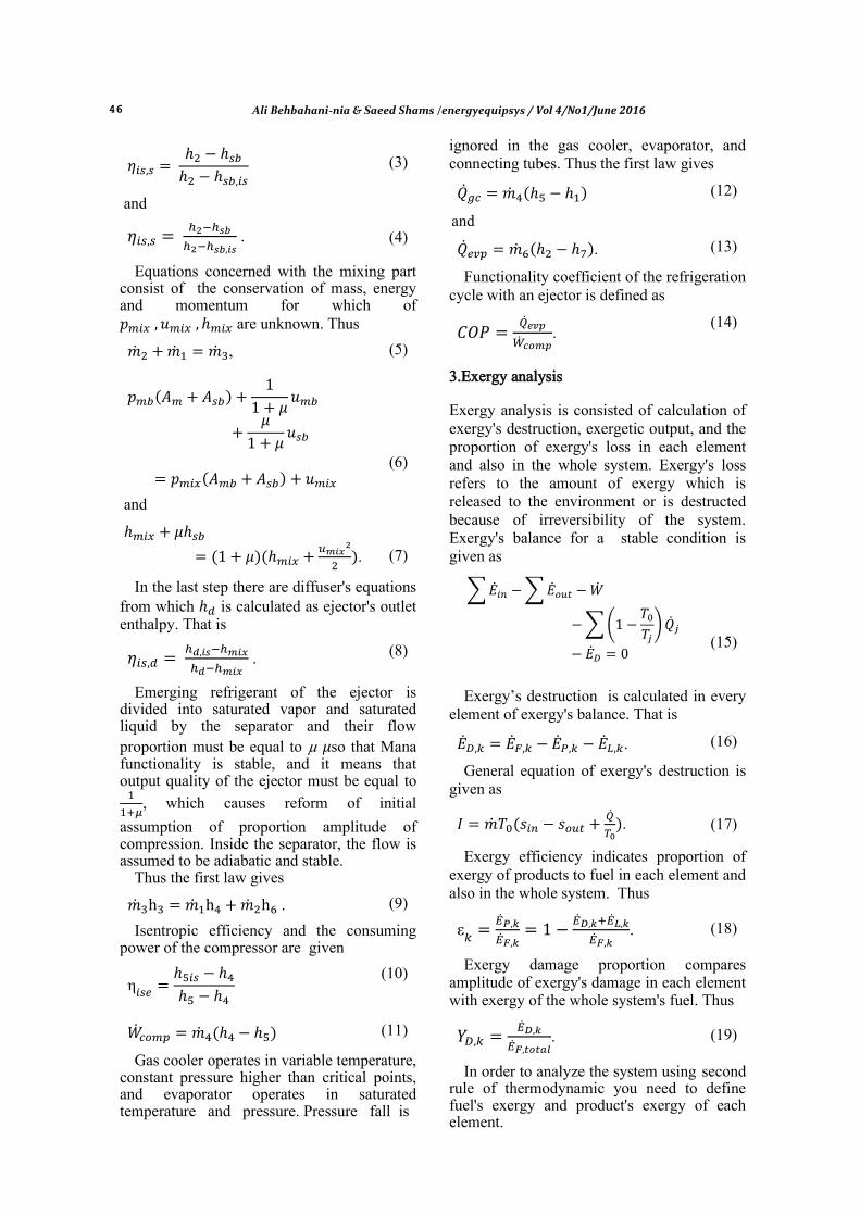
(3)
and
.
(4)
Equations concerned with the mixing part consist of the conservation of mass, energy and momentum for which of are unknown. Thus
, (5)
(6)
and
.
(7)
In the last step there are diffuser's equations from which is calculated as ejector's outlet enthalpy. That is
. (8)
Emerging refrigerant of the ejector is divided into saturated vapor and saturated liquid by the separator and their flow proportion must be equal to µ so that Mana functionality is stable, and it means that output quality of the ejector must be equal to
, which causes reform of initial
assumption of proportion amplitude of compression. Inside the separator, the flow is assumed to be adiabatic and stable.
Thus the first law gives
. (9)
Isentropic efficiency and the consuming power of the compressor are given
η
(10)
(11)
Gas cooler operates in variable temperature, constant pressure higher than critical points, and evaporator operates in saturated temperature and pressure. Pressure fall is
ignored in the gas cooler, evaporator, and connecting tubes. Thus the first law gives
(12)
and
. (13)
Functionality coefficient of the refrigeration cycle with an ejector is defined as
.
(14)
3.Exergy analysis Exergy analysis is consisted of calculation of exergy's destruction, exergetic output, and the proportion of exergy's loss in each element and also in the whole system. Exergy's loss refers to the amount of exergy which is released to the environment or is destructed because of irreversibility of the system. Exergy's balance for a stable condition is given as
∑ ∑
∑(
)
(15)
Exergy’s destruction is calculated in every element of exergy's balance. That is
. (16)
General equation of exergy's destruction is given as
.
(17)
Exergy efficiency indicates proportion of exergy of products to fuel in each element and also in the whole system. Thus
ε
.
(18)
Exergy damage proportion compares amplitude of exergy's damage in each element with exergy of the whole system's fuel. Thus
.
(19)
In order to analyze the system using second rule of thermodynamic you need to define fuel's exergy and product's exergy of each element.
Ali Behbahani-nia & Saeed Shams /energyequipsys / Vol 4/No1/June 2016 47
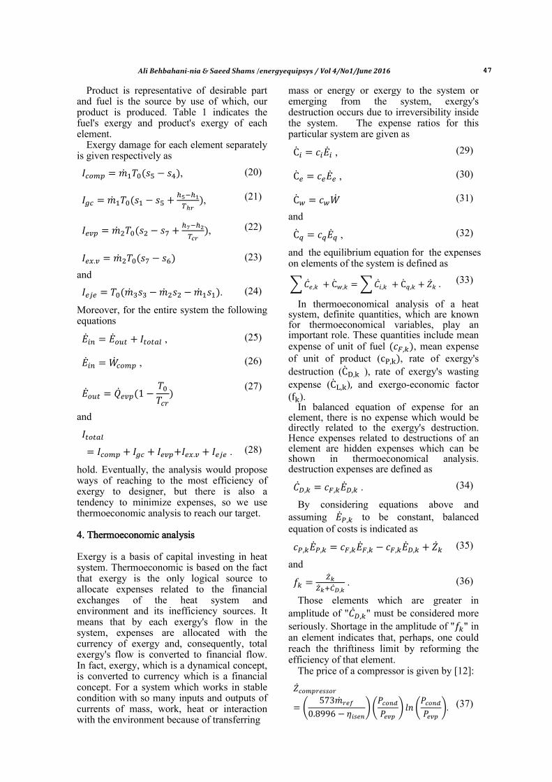
Product is representative of desirable part and fuel is the source by use of which, our product is produced. Table 1 indicates the fuel's exergy and product's exergy of each element.
Exergy damage for each element separately is given respectively as
, (20)
, (21)
, (22)
(23)
and
. (24)
Moreover, for the entire system the following equations
, (25)
, (26)
(27)
and
.
(28)
hold. Eventually, the analysis would propose ways of reaching to the most efficiency of exergy to designer, but there is also a tendency to minimize expenses, so we use thermoeconomic analysis to reach our target. 4. Thermoeconomic analysis Exergy is a basis of capital investing in heat system. Thermoeconomic is based on the fact that exergy is the only logical source to allocate expenses related to the financial exchanges of the heat system and environment and its inefficiency sources. It means that by each exergy's flow in the system, expenses are allocated with the currency of exergy and, consequently, total exergy's flow is converted to financial flow. In fact, exergy, which is a dynamical concept, is converted to currency which is a financial concept. For a system which works in stable condition with so many inputs and outputs of currents of mass, work, heat or interaction with the environment because of transferring
mass or energy or exergy to the system or emerging from the system, exergy's destruction occurs due to irreversibility inside the system. The expense ratios for this particular system are given as
, (29)
, (30)
(31)
and
, (32)
and the equilibrium equation for the expenses on elements of the system is defined as
∑ ∑ (33)
In thermoeconomical analysis of a heat system, definite quantities, which are known for thermoeconomical variables, play an important role. These quantities include mean expense of unit of fuel , mean expense of unit of product ( , rate of exergy's destruction ( ), rate of exergy's wasting expense ( ) and exergo-economic factor ( ).
In balanced equation of expense for an element, there is no expense which would be directly related to the exergy's destruction. Hence expenses related to destructions of an element are hidden expenses which can be shown in thermoeconomical analysis. destruction expenses are defined as
. (34)
By considering equations above and assuming to be constant, balanced equation of costs is indicated as
(35)
and
. (36)
Those elements which are greater in amplitude of " " must be considered more seriously. Shortage in the amplitude of " " in an element indicates that, perhaps, one could reach the thriftiness limit by reforming the efficiency of that element.
The price of a compressor is given by [12]:
(
)(
) (
)
(37)
48 Ali Behbahani-nia & Saeed Shams /energyequipsys / Vol 4/No1/June 2016
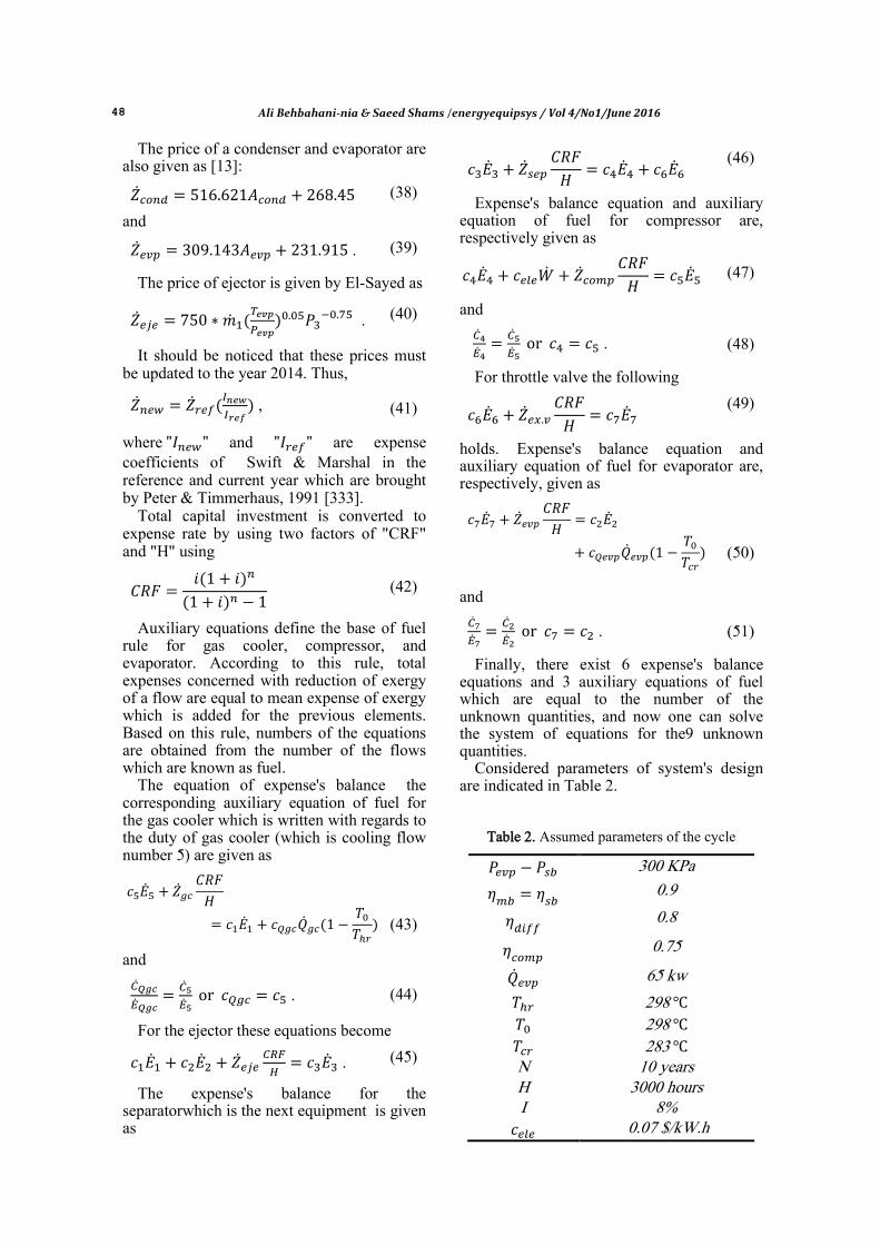
The price of a condenser and evaporator are also given as [13]:
(38)
and
. (39)
The price of ejector is given by El-Sayed as
. (40)
It should be noticed that these prices must be updated to the year 2014. Thus,
,
(41)
where and are expense coefficients of Swift & Marshal in the reference and current year which are brought by Peter & Timmerhaus, 1991 [333].
Total capital investment is converted to expense rate by using two factors of "CRF" and "H" using
(42)
Auxiliary equations define the base of fuel rule for gas cooler, compressor, and evaporator. According to this rule, total expenses concerned with reduction of exergy of a flow are equal to mean expense of exergy which is added for the previous elements. Based on this rule, numbers of the equations are obtained from the number of the flows which are known as fuel.
The equation of expense's balance the corresponding auxiliary equation of fuel for the gas cooler which is written with regards to the duty of gas cooler (which is cooling flow number 5) are given as
(43)
and
.
(44)
For the ejector these equations become
. (45)
The expense's balance for the separatorwhich is the next equipment is given as
(46)
Expense's balance equation and auxiliary equation of fuel for compressor are, respectively given as
(47)
and
.
(48)
For throttle valve the following
(49)
holds. Expense's balance equation and auxiliary equation of fuel for evaporator are, respectively, given as
(50)
and
.
(51)
Finally, there exist 6 expense's balance equations and 3 auxiliary equations of fuel which are equal to the number of the unknown quantities, and now one can solve the system of equations for the9 unknown quantities.
Considered parameters of system's design are indicated in Table 2.
Table 2. Assumed parameters of the cycle
300 KPa
0.9
0.8
0.75
65 kw
298 298 283 N 10 years H 3000 hours I 8%
0.07 $/kW.h

Ali Behbahani-nia & Saeed Shams /energyequipsys / Vol 4/No1/June 2016 49
5. Optimization Thermoeconomical target function is indicated in the term 53 and consists of yearly capital investment of the equipment and yearly electricity consumed by the compressor, and its decision variables are emerging temperature of the gas cooler , emerging pressure of gas cooler , and evaporator's temperature which their relation is indicated as
.
(52)
Finally one has
∑ ∑
(53)
6. Discussion and Conclusions Basic design of the cycle is designed using assumed parameters of Table 2 and change effects of decision's variables on exergy's destruction and its capital investment are considered.
Figure 3 indicates exergy's destruction changes based on gas cooler's 7.c of evaporator. Total exergy's destruction is increased by increase of gas cooler's pressure and temperature. The most exergy's destruction is caused by gas cooler which has a proportion of 45% of the total exergy's destruction.
Figure 4 indicates exergy's destruction changes based on evaporator's temperature in the temperature of 20˚C and pressure of 9000 kpa of gas cooler. By increase of evaporator's temperature, total exergy's destruction decreases. Also, exergy's destruction of each element decreases except in "expansion value".
⁄
(54)
Fig. 3. Exergy's destruction changes based on gas cooler's temperature
Fig. 4. Exergy’s destruction changes based on evaporator's temperature
3
8
13
18
23
28
20 25 30 35 40 45
Tota
l Exe
rgy
Dis
tru
ctio
n (
KW
)
outlet temperature of gas cooler (°C)
P=8000
P=8500
P=9000
P=9500
P=10000
P=10500
P=11000
5
6
7
8
9
10
11
12
13
14
-10 -5 0 5 10
Tota
l Exe
rgy
Dis
tru
ctio
n (
KW
)
Evaporator temperature (°C)

50 Ali Behbahani-nia & Saeed Shams /energyequipsys / Vol 4/No1/June 2016
Figure 5 indicates that by increasing gas cooler's pressure, exergy's destruction increases.
Figure 6 indicates total capital investment's changes based on emerging pressure of gas cooler which is plotted for the emerging gas cooler in temperature range of 20 to 40. This diagram indicates thermoeconomical optimum point in various temperatures, in which optimum pressure point is located out of determined interval for temperatures below 35˚C. Minimum amplitude of target function is the first point of the interval and optimum point is visible for the temperatures higher than 35˚C.
Capital investment for gas cooler and ejector are reduced by increasing emerging
pressure of gas cooler and for the compressor it decreases at first and then it increases.
Figure 7 indicates total capital investment's changes based on emerging temperature of gas cooler at the pressure of 9000kpa and evaporator's temperature of 7˚C. By increase of the temperature, compressor's operation is increased and following that, capital investment of the compressor, ejector, and gas cooler increase. Ejector's pressure ratio increases from 1.24 to 1.44 and suction ratio decreases from 0.93 to 0.22. This diagram is plotted in different pressures of the gas cooler and by decrease of the pressure the sharp slope of the end of the diagram becomes sharper and moves forward, and these changes is visible up to critical temperature and pressure of CO2 in 30.98˚C and 7377 kpa.
Fig. 5. Exergy’s destruction changes based on gas cooler's pressure
Fig. 6. Capital investment's changes based on gas cooler's pressure
6
6.5
7
7.5
8
8.5
9
9.5
10
9000 9500 10000 10500 11000
Tota
l Exe
rgy
Dis
tru
ctio
n (
KW
)
Outlet Pressure of gas cooler (KPa)
0.4
0.5
0.6
0.7
0.8
0.9
1
1.1
9000 10000 11000 12000
c_e
le (
$/k
w.h
)
Outlet Pressure of gas cooler (KPa)
Tgc=42CTgc=40CTgc=38CTgc=34CTgc=30CTgc=25CTgc=20C

Ali Behbahani-nia & Saeed Shams /energyequipsys / Vol 4/No1/June 2016 51
Fig. 7. Capital investment changes based on gas cooler’s temperature.
Figure 8 indicates total capital investment
changes based on evaporator's temperature at the pressure of 9000kpa and gas cooler's temperature of 20˚C. 7˚C is the optimum temperature of it. By increasing evaporator's temperature, compressor's operation and capital investment of the compressor and ejector decrease and increases in gas cooler and evaporator.
Table 3 compares thermoeconomical optimum point and the base point (11) and indicates that thermoeconomical analysis decreased product's expense up to 35%. Fuel expenses are also decreased about 48% which indicates decrease of mass flow of the fuel. 60% decrease in exergy's destruction and 21% decrease in total capital investment are also indicated. 93% increase for both exergy's efficiency and thermodynamic functionality are indicated.
7. Conclusion In this article, thermoeconomical optimization method of transcritical CO2 refrigeration cycle with an ejector was presented. In the study, both thermodynamic and economical aspects of the cycle were considered and thermoeconomic optimum point of the system was obtained by the target function of current and yearly capital investment and genetic optimization algorithm.
Refrigeration capacity, temperature of warm and cool environment, evaporator's temperature, gas cooler's temperature and pressure are decision variables. The optimum amplitude of decision variables are as , and .
As mentioned before, both thermodynamic functionality and exergetic efficiency of the cycle have 93% increase and total yearly capital investment has 34% decrease in consequence of application of this method.
Fig. 8. Capital investment changes based on evaporator’s temperature.
0.4
0.5
0.6
0.7
0.8
0.9
1
1.1
1.2
20 25 30 35 40 45
c p (
$/k
W.h
)
Outlet Temperature of gas cooler (°C)
0.41
0.43
0.45
0.47
0.49
0.51
0.53
-15 -10 -5 0 5 10
c p ($
/kW
.h)
Outlet Temperature of evaporator (°C)

52 Ali Behbahani-nia & Saeed Shams /energyequipsys / Vol 4/No1/June 2016
Table 3. Fuel comparison in two optimum and base conditions
Optimum pint Base point
0.1999 0.2743 ,($/h)
0.1193 0.2555 ,($/h)
0.0052 0.0086 ,($/h)
0.2623 0.2060 ,($/h)
0.1986 0.1986 ,($/h)
0 0 ,($/h)
0.7853 0.9430 ,($/h)
0.6559 1.2656 ,($/h)
1.4413 2.2092 ,($/h)
0.4107 1.0248 ,($/h)
0.3677 0.1905 Exergetic efficiency of
the sys. %
6.937 3.595 COP
9000 10000 ,KPa
20 40 ,°C
7 5 ,°C
References [1]Kornhauser, A. A., The Use of an Ejector
as a Refrigerant Expander, Proceedings of the 1990 USNC/IIR–Purdue Refrigeration Conference (1990) 10-19.
[2]Ozaki Y, Takeuchi H, Hirata T., Regeneration of Expansion Energy by Ejector in CO2 Cycle. Proceedings of Sixth IIRG. Lorentzen Natural Working Fluid Conference (2004) 142-149
[3]Working group, Intergovernmental Panel on Climate Change. Climate Change (2001).
[4]Neksa P., CO2 Heat Pump Systems, International Journal of Refrigeration (2002) 25: 421–7.
[5]Kim M.H., Pettersen J., Bullard C.W., Fundamental Process and System Design Issues in CO2 Vapor Compression Systems, Progress in Energy and Combustion Science (2004) 30: 41-49.
[6]Liu JP, Chen JP, Chen ZJ, Thermodynamic Analysis on Trans-Critical R744 Vapor Compression/Ejection Hybrid Refrigeration Cycle, Proceedings of Fifth IIR G. Lorentzen Conference on Natural Working Fluids, Guangzhou (2002).
[7] Fangtian S., Yitai M., Thermodynamic Analysis of Transcritical CO2 Refrigeration Cycle with an Ejector, Tianjin Conference, China(2010).
[8] Elbel S.W., Hrnjak P.S., Effect of Internal Heat Exchanger on Performance of Transcritical CO2 Systems with Ejector, Tenth International Refrigeration and Air Conditioning Conference at Purdue,West Lafayette (2004).
[9] Ozaki Y., Takeuchi H., Hirata T., Regeneration of Expansion Energy by Ejector in CO2 Cycle, Proceedings of Sixth IIRG. Lorentzen Natural Working Fluid Conference, Glasgow, UK (2004).
[10] Sarkar J., Ejector Enhanced Vapor Compression Refrigeration and Heat Pump Systems-A Review, Department of Mechanical Engineering. Indian Institute of Technology (B.H.U.), India (2012).
[11]Li D, Groll E.A., Transcritical CO2 Refrigeration Cycle with Ejector-Expansion Device, International Journal Refrigeration (2005) 28: 766–73.
[12]Valero, A., CGAM problem: definition and conventional solution. Energy,(1994) 19. pp 268-279.
[13]Selbas R., Kızılkan O., Sencana A., Economic Optimization of Subcooled and Superheated Vapor Compression, Energy (2006) 31: 2108-2128
[14] E1-Sayed Y.M., Designing Desalination Systems for Higher Productivity, Advanced Energy Systems Analysis, Higgins Way, Fremont, USA (2005).