in general, all geotechnical design recommendations … · chapter 21 geotechnical ......
TRANSCRIPT

Oregon Department of Transportation Geotechnical Design Manual November 2017
21-1
Chapter
21 Geotechnical Reporting and Documentation 21.1 General ODOT geotechnical engineers, engineering geologists and consultants working on ODOT projects, produce geotechnical reports, engineering geology reports and other various design memorandums, documents and products in support of project definition, project design, and final PS&E development. Also produced are project specific Special Provisions, plan details, boring logs, Geotechnical Data Sheets and the final project geotechnical documentation. Information developed to support these geotechnical documents are retained in the project files in Project Wise. The information includes project site data, regional and site specific geologic data, exploration logs, field and laboratory test results, instrumentation and monitoring data, interpretive drawings, design calculations, and construction support documents. This chapter provides standards for the development, content, and review of these documents and records, with the exception of borings logs, which are covered in Chapter 4 and Materials Source Reports, which are covered in Chapter 20.
Project geotechnical documentation and records produced by ODOT staff, and consultants working on ODOT projects, shall meet, as applicable, the informational requirements listed in the following FHWA manual:
• FHWA, 2003, Checklist and Guidelines for Review of Geotechnical Reports and Preliminary Plans and Specifications, Publication No. FHWA ED-88-053, Updated edition.
A copy of this manual can be obtained and downloaded from the Geo-Environmental web site. The FHWA manual includes “Geotechnical Report Review Checklists,” covering the main information and recommendations that should be addressed in project geotechnical reports. In addition to these FHWA checklists, the ODOT checklist provided in Appendix 21-A Geotechnical Report Review Checklist covers additional items that should be included in the review of all bridge foundation design projects. These checklists should be used as the basis for evaluating the completeness of the final geotechnical or engineering geology reports and products.
21.2 General Reporting Requirements In general, all geotechnical design recommendations should be documented with either a stamped hard copy to the project file or a stamped electronic copy. Verbal recommendations that influence contract plans or specifications or result in design changes should be followed up with a formal document. It is recognized that some geotechnical recommendations may involve very minor design or construction issues and therefore minimal review or documentation is required. The level of review and documentation depends on the type and complexity of the design or construction issue and the

Oregon Department of Transportation Geotechnical Design Manual November 2017
21-2
experience and qualifications of the engineer performing the work. It is the responsibility of each Region Technical Center to establish the quality control procedures and protocol, and the levels of review and documentation required, for all geotechnical work produced by its office.
A geotechnical document (either a design memorandum or standard report) is required for most highway projects involving any significant geotechnical design elements such as earthwork, landslides or rock slopes, or structure foundations. When geotechnical design is required for a project, this work should be documented in the form of either technical memoranda or reports that summarize the work performed and the resulting design recommendations and products. For reports that cover individual project elements, a geotechnical design memorandum may suffice, with the exception of bridge reports and major unstable slope repair projects, in which case a formal geotechnical report should be issued.
E-mail may be used for geotechnical reporting and for providing recommendations in certain circumstances. E-mails may be used to transmit review of construction submittals or to transmit preliminary foundation or other preliminary geotechnical recommendations. In both cases, a print-out of the e-mail should be included in the project file. For time critical geotechnical designs sent by e-mail that are not preliminary, the e-mail should be followed up with a stamped memorandum or report as soon as possible. A copy of the e-mail should also be included in the project file.
21.3 Quality Control Quality control of geotechnical design work should be an ongoing process occurring regularly throughout the entire design process. Each Region Tech Center is responsible for the quality control of the geotechnical products produced in its region. These products should adhere to the ODOT geotechnical standards of practice established and defined in the ODOT Geotechnical Design Manual.
21.3.1 Quality Control for Bridge Foundation Design For most routine bridge foundation design projects, the subsurface investigation program, materials classification and testing, recommended foundation type, design calculations, design recommendations, special provisions, reports and Geotechnical Data Sheets should all be thoroughly reviewed by an independent geotechnical engineer with intimate knowledge of the project. This review should be thorough enough to verify and confirm all design assumptions and calculations leading to the recommendations made in the report. Important geologic interpretations made for foundation design purposes should be reviewed and approved by a Certified Engineering Geologist (CEG), and noted so by stamping and sealing the final geotechnical data report. All design memorandum and geotechnical reports should be stamped and sealed by the appropriate Professional of Record (POR), registered in the state of Oregon, whose area of expertise is in geotechnical engineering. Each of these documents shall also be signed by the reviewer.
Geotechnical Data Sheets may be stamped by either a Registered Professional Engineer (PE) or a Certified Engineering Geologist (CEG). Geotechnical Data Sheets must be independently checked by a geotechnical engineer or an engineering geologist familiar with the project. It should be understood that the Geotechnical Data Sheets are important contract document that are sometimes used in the resolution of contract claims submitted by contractors under the Differing Site Conditions clause (Section 00140.40). Therefore, the person stamping the Geotechnical Data Sheet should have a complete understanding of what is being constructed based on the data sheet and how the data sheet information can affect the foundation construction, contract bidding and claim potential.

Oregon Department of Transportation Geotechnical Design Manual November 2017
21-3
21.4 Geotechnical Report Content Requirements The geotechnical information and types of recommendations that should be provided in geotechnical reports or memorandum is provided in the sections that follow. Both preliminary (TS&L) reports and final reports are addressed.
21.4.1 Preliminary Geotechnical Reports Preliminary geotechnical reports are typically used to provide geotechnical input for the following:
• Developing the project definition,
• Development of TS&L bridge plans,
• Conceptual geotechnical studies for environmental permit development activities,
• Reconnaissance level corridor studies,
• Development of EIS discipline studies, and
• Rapid assessment of emergency repair needs (e.g., landslides, rock fall, bridge foundation scour, etc.).
Preliminary geotechnical reports are often developed primarily based on an office review of existing geotechnical data for the site, and generally consist of feasibility assessment, identification of geologic hazards and preliminary recommendations. Geotechnical design for preliminary reports is typically based largely on engineering judgment and experience at the site, or similar sites, combined with whatever existing geologic and geotechnical information is available. At this stage (especially for bridge projects), a geological reconnaissance of the project site has usually been conducted and in some cases a subsurface exploration program is in progress and some preliminary geotechnical analysis can be performed to characterize key elements of the design, assess potential hazards, evaluate potential design alternatives and estimate preliminary costs.
These preliminary geotechnical reports should contain the following information as applicable to the project. Refer to Section 21.4.1.1 for additional preliminary report requirements related to bridge foundations.
• A general description of the project, project elements, and project background.
• A brief summary of the regional and site geology. The amount of detail included here will depend on scope of the project. For example, a landslide repair project will require a more detailed discussion of the site and regional geology than a routine bridge replacement project.
• A summary of the available site data, including as-built information.
• A summary of the field exploration conducted, if applicable.
• A summary of the laboratory testing conducted, if applicable.
• A description of the project soil and rock conditions. The amount of detail included here will depend on the type of report. For projects in which new borings have been obtained, soil profiles for key project features (e.g., bridges, major walls, etc.) may need to be developed and tied to this description of project soil and rock conditions.
• A summary of geological hazards identified that may affect the project design (e.g., landslides, rock fall, debris flows, liquefaction, soft ground or otherwise unstable soils, seismic hazards, etc.), if any.

Oregon Department of Transportation Geotechnical Design Manual November 2017
21-4
• A summary of the preliminary geotechnical recommendations.
• Appendices that include any boring logs and laboratory test data obtained (old or new), soil profiles developed, any field data obtained, and any photographs.
Prel iminary Geotechnical Reports for Bridge 21.4.1.1Foundation Projects
For bridge foundation design projects, a preliminary geotechnical report (TS&L Memo) should be provided to the bridge designer early on in the design process. Maintain close communication and coordination with the bridge designer to see when this information is required. As a general rule, the memo should be provided no later than two-thirds of the way through the TS&L design process. The purpose of this memo is to provide sufficient data for developing TS&L plans and cost estimates and for permitting purposes. The memo is generally provided before the subsurface investigation is completed but may contain some subsurface information, such as preliminary drilling results, performed up to that date. It provides a brief description of the proposed project, the anticipated subsurface conditions (based on existing geologic knowledge of the site, as-built plans and records and other existing information), and presents preliminary foundation design recommendations such as foundation types and preliminary resistances. The rational for selecting the recommended foundation type should be presented. The potential for liquefaction and associated effects should also be discussed as well as any other geologic hazards that may affect design.
The document should be stamped by the geotechnical engineer (POR) and also the project engineering geologist if significant geologic interpretations or other geologic input were used in developing the recommendations. The memo may be distributed in the form of an email message or a full report depending on the size and scope of the project. If the memo is distributed by email a hard copy should also be printed out, sealed and dated by the engineer, and placed in the project file.
Note: The TS&L memo does not meet the requirements of a final Geotechnical Report, which is required for all bridge projects involving foundation work.
21.4.2 Final Geotechnical Reports In general, final geotechnical reports are developed based on an office review of existing geotechnical data for the site, a detailed geologic review of the site, and a complete subsurface investigation program, meeting AASHTO and FHWA standards. Design analysis are then conducted based on the results of the field investigation work, combined with any institution or laboratory test data, and the resulting design recommendations are included in the geotechnical report along with construction recommendations and project special provisions as appropriate.
Geotechnical reports for bridge foundation design projects are used to communicate and document the site and subsurface conditions along with the foundation and construction recommendations to the structural designer, specifications writer, construction personnel, and other appropriate parties. The importance of preparing a thorough and complete geotechnical report cannot be overemphasized. The information contained in the report is referred to during the design phase, the pre-bid phase, during construction, and occasionally in post-construction to assist in the resolution of contractor claims.
The following reporting guidelines are provided for use in developing the final Geotechnical Report. Also refer to the Geotechnical Report Review Checklist in Appendix 21-A Geotechnical Report Review Checklist for guidance on the general format and information that should be contained in Geotechnical Reports specific to structure foundations. Include all items below that apply to the project.

Oregon Department of Transportation Geotechnical Design Manual November 2017
21-5
Description A general description of the project scope, project elements, and project background.
Surface Conditions Project site surface conditions and current use.
Regional and Site Geology This section should describe the site stress history and depositional/erosional history, bedrock and soil geologic units, etc.
Regional and Site Seismicity This section should identify the major seismic sources affecting the site including nearby active faults. This section is generally only included in reports addressing structural elements (e.g., bridges, walls, etc.) and major earthwork projects. Refer to Chapter 6 for additional seismic design criteria that may be required.
Summary of Office Studies A summary of the office studies collected on the site, including final construction records for previous construction activity at the site, as-built bridge drawings or other structure layouts, pile records, boring or test pit logs or other subsurface information, geologic maps or previous or current geologic reconnaissance results.
Summary of Field Exploration A summary of the field exploration conducted, if applicable. Provide a description of the methods and standards used, as well as a summary of the number and types of explorations and field testing that were conducted. Include a plan map (or data sheet) in the appendix showing the locations of all explorations. Also include a description of any field instrumentation installed and its purpose, data and results. Provide exploration logs in the report appendices along with any other field test data such as cone penetrometer, pressure meter, vane shear tests, or shear wave velocity profiles.
Summary of Laboratory Testing A summary of the laboratory testing conducted, if applicable. Provide a description of the methods and standards used as well as a summary of the number and types of tests that were conducted. Provide the detailed laboratory test results in the report appendices.
Soil and Rock Materials and Subsurface Conditions This section should include not only a description of the soil/rock units encountered, but also how the units are related at the site, and their geologic origin. The soil and rock units should also be discussed in terms of the relevance and influence the materials and conditions may have on the proposed construction. Groundwater conditions should be described in this section of the report, including the identification and discussion of any confined aquifers, artesian pressures, perched water tables, potential seasonal variations, if known, any influences on the groundwater levels observed, and direction and gradient of groundwater, if known. The groundwater elevation is a very important item and should be provided in the report. The measured depth of groundwater levels, and dates measured, should be noted on the exploration logs and discussed in the report. It is important to distinguish between the groundwater level and the level of any drilling fluid. In addition, groundwater levels encountered during exploration may differ from design groundwater levels. Any artesian or unusual groundwater conditions should be noted as this often has

Oregon Department of Transportation Geotechnical Design Manual November 2017
21-6
important effects on foundation design and construction. If rock slopes are present, discuss rock structure, including the results of any field structure mapping (use photographs as needed), joint condition, rock strength, potential for seepage, etc.
Subsurface Profiles Descriptions of soil and rock conditions should always be illustrated with subsurface profiles (i.e., parallel to roadway centerline) and cross-sections (i.e., perpendicular to roadway centerline) of the key project features.
A subsurface profile or cross-section is defined as a graphical illustration that assists the reader of the geotechnical report to visualize the spatial distribution of the soil and rock units encountered in the borings for a given project feature (e.g., structure, cut, fill, landslide, etc.).
Cross sections and profiles along certain features, such as landslides, may be needed to fully convey the site conditions and subsurface model. These profiles and cross sections help to define a geologic model of the subsurface materials and conditions. As such, the profile or cross-section will contain the existing and proposed ground line, the structure profile or cross-section if one is present, the boring logs (including SPT values, soil/rock units, etc.), and the location of any water table(s). Interpretive information should be provided in these illustrations, as appropriate, to adequately and clearly describe and depict the subsurface geologic model. The potential for variability in any of the stratification shown should also be discussed in the report.
Geotechnical Data Sheets An unstamped figure of the final Geotechnical Data Sheets should always be provided in the Geotechnical Data Report and/or the Geotechnical Report.
Summary of Geologic Hazards Provide a summary of geological hazards identified and their impact on the project design (e.g., landslides, rock fall, debris flows, liquefaction, soft ground or otherwise unstable soils, seismic hazards, etc.), if any. Describe the location and extent of the geologic hazard.
Analysis of Unstable Slopes For analysis of unstable slopes (including existing settlement areas), cuts, and fills, provide the following:
• Analysis approach,
• Assessment of failure mechanisms,
• Determination of design parameters (including residual shear strength as applicable),
• Factors of safety used, and
• Any agreements within ODOT or with other customers regarding the definition of acceptable level of risk.
Included in this section, would be a description of any back-analyses conducted, the results of those analyses, comparison of those results to any laboratory test data obtained, and the conclusions made regarding the parameters that should be used for final design.
Recommendations for Stabilization of Unstable Slopes Provide geotechnical recommendations for stabilization of unstable slopes (e.g., landslides, rock fall areas, debris flows, etc.). This section should provide the following information and recommendations as appropriate:

Oregon Department of Transportation Geotechnical Design Manual November 2017
21-7
• A discussion of the mitigation options available,
• Detailed recommendations regarding the most feasible options for mitigating the unstable slope,
• A discussion of the advantages, disadvantages, and risks associated with each feasible option,
• Cost estimates for each option should also be included, as appropriate.
Earthwork Recommendations Provide a summary of geotechnical recommendations for earthwork (embankment design, cut slope design, drainage design, and use of on-site materials as fill). This section should provide the following recommendations as applicable to the project:
• Embankment design recommendations, such as the maximum embankment slope angles, allowed for stability and any measures that need to be taken to provide a stable embankment (e.g., geosynthetic reinforcement, wick drains, staged embankment construction, surcharge, lightweight materials, etc.),
• Estimated embankment settlement and settlement rate, along with any recommendations for mitigating excess post construction settlement. Include any recommendations for foundation improvement (sub-excavation) such as the need for removal of any unsuitable materials beneath the proposed fills and the extent of these areas,
• Cut slope design recommendations, including the maximum cut slopes allowed to maintain the required stability. Recommendations for control of seepage or piping, erosion control measures and any other special measures (such as horizontal drains) required to provide a stable slope should be provided,
• Regarding the use of on-site materials, on-site soil units should be identified as to their feasibility for use as embankment material, discussing the type of material for which the on-site soils are feasible, the need for aeration, the effect of weather conditions on their usability, and identification of on-site materials that should definitely not be used in embankment construction. The degradation potential of rock materials should be identified and discussed, as appropriate.
Rock Slope and Rock Excavation Recommendations Provide geotechnical recommendations for rock slopes and rock excavation. Such recommendations should include, but are not limited to the following:
• Recommended rock slope design and fallout area (if appropriate),
• Rock scaling,
• Rock bolting/dowelling, and other stabilization requirements (if appropriate), including recommendations to prevent erosion/undermining of intact blocks of rock,
• Internal and external slope drainage requirements,
• Feasible methods of rock removal such as blasting or ripping,
• Detailed plans and cross sections as needed to clearly depict the areas requiring rock slope stabilization and the methods and designs recommended.
Bridge and Other Structure Recommendations

Oregon Department of Transportation Geotechnical Design Manual November 2017
21-8
Provide geotechnical recommendations for bridges, tunnels, hydraulic structures, and other structures. See Section 21.7 for additional information required for bridge foundation designs. This section should provide the following minimum information:
• Discussion of foundation options considered,
• Recommended foundation options, and the reason(s) for the selection of the recommended option(s),
• Foundation design recommendations:
o For strength limit state – nominal and factored bearing resistance, lateral and uplift resistances,
o For service limit state – settlement limited bearing, and any special design requirements,
o For extreme event limit state – nominal bearing, uplift, and lateral resistance, and soil spring values,
o Design recommendations for scour, when applicable.
Seismic Design Parameters and Recommendations Provide the following for seismic design parameters and recommendations:
• Site location latitude and longitude decimal format to at least four digits,
• Three point design spectra using the General Procedure in AASHTO for the 2014 USGS seismic hazard maps for the 1000-year events,
• Eighteen point design spectra based on the CSZ Earthquake event (for bridges on and west of US97)
• Site Class and Soil Coefficients (Fpga, Fa, Fv),
• Design Response Spectrum (from AASHTO General Procedure and/or Ground Response Analysis).
Summary of Liquefaction Analysis Provide a summary of liquefaction analysis. If liquefaction is predicted, provide:
• Estimates of embankment deformations including predicted settlement and lateral displacements,
• An assessment of potential bridge damage and approach fill performance for both the 500 and 1000 year events,
• Estimates of seismic-induced downdrag loads (if applicable),
• Soil properties for both the liquefied and non-liquefied soil conditions, for use in the lateral load analysis of deep foundations,
• Reduced foundation resistances,
• Liquefaction mitigation design recommendations (if necessary),
• Results of ground response analysis (SHAKE) and site-specific response spectra (if applicable),

Oregon Department of Transportation Geotechnical Design Manual November 2017
21-9
• Earth pressures on abutments and walls in buried structures.
Retaining Wall and Reinforced Slope Recommendations Provide geotechnical recommendations for retaining walls and reinforced slopes. This section should provide a discussion of:
• Wall/reinforced slope options and the reason(s) for the selection of the recommended option(s),
• Foundation type and design requirements:
o For strength limit state - bearing resistance, lateral and uplift resistance if deep foundations selected,
o For service limit state - settlement limited bearing, and any special design requirements,
o Seismic design parameters and recommendations (e.g., design acceleration coefficient, extreme event limit state bearing, uplift and lateral resistance if deep foundations selected) for all walls except for ODOT Standard Retaining Walls,
o Design considerations for scour when applicable,
o Lateral earth pressure parameters (provide full earth pressure diagram for non-gravity cantilever walls and anchored walls).
Non-Proprietary Walls and Reinforced Slopes For non-proprietary walls/reinforced slopes requiring internal stability design (e.g., geosynthetic walls, soil nail walls, and all reinforced slopes), provide the following:
• Minimum width for external and overall stability,
• Embedment depth,
• Bearing resistance,
• Settlement estimates,
• Soil/rock adhesion values,
• Soil reinforcement spacing, strength, and length requirements in addition to dimensions to meet external stability requirements,
• Or anchored walls, provide achievable anchor capacity, no load zone dimensions, and design earth pressure distribution.
Proprietary Walls For proprietary walls, provide the following:
• Minimum width for external and overall stability,
• Embedment depth,
• Bearing resistance,
• Settlement estimates,
• Design parameters for determining earth pressures.

Oregon Department of Transportation Geotechnical Design Manual November 2017
21-10
Traffic Structure, Soundwall and Building Recommendations Provide geotechnical recommendations for traffic structures, soundwalls and buildings. This section should provide the following minimum information:
Provide the following foundation information:
• Discussion of foundation options considered,
• Recommended foundation options, and the reason(s) for the selection of the recommended option(s),
• Foundation design recommendations.
For mast arm signal and strain poles, provide soils information required for the Broms method. This includes soil type (cohesive or cohesionless), unit weight, soil friction angle or un-drained shear strength and groundwater level. Provide the highest groundwater level anticipated at any time during the life of the structure. If site conditions do not allow the use of the Broms method, provide soils information required for the LPile or strain-wedge analysis methods as appropriate.
For structures that have standard foundation design drawings, provide the site-specific soil designation (i.e. “Good,” “Average” or Type “A” or “B,” etc.) for use with the standard drawing. Also provide recommendations on whether or not the foundation soils and site conditions meet all requirements shown on the standard drawing, such as slope limits and settlement criteria. If soil or site conditions are variable along the length or under the foundation, clearly delineate these areas on a plan map and provide recommendations for each delineated area.
If the foundation materials or site conditions do not meet the requirements for using the standard drawings, such as conditions of hard rock or very soft, “Poor” soils, provide soil unit descriptions, soil properties, groundwater information and other design recommendations as required for design of the foundation to support the proposed structure. This includes the following information as a minimum:
• Description of the soil units using the ODOT Soil & Rock Classification System,
• Ground elevation and elevations of soil/rock unit boundaries,
• Depth to the water table,
• Soil design parameters, including effective unit weight(s), cohesion, φ, Ka, Kp, and/or P-y curve or strain-wedge data as appropriate,
• The allowable bearing capacity for spread footings and estimated wall or footing settlement (and differential settlement) as appropriate,
• Overall stability factor of safety,
• Any foundation constructability issues resulting from the soil/rock or groundwater conditions.
Recommendations for Infiltration/Detention Facilities Provide geotechnical recommendations regarding infiltration rate, impact of infiltration on adjacent facilities, effect of infiltration on slope stability, if the facility is located on or near a slope, stability of slopes within the pond, and foundation bearing resistance and lateral earth pressures (vaults only). See the “ODOT Hydraulics Manual” for additional details on what is required for these types of facilities.

Oregon Department of Transportation Geotechnical Design Manual November 2017
21-11
Recommendations for Non-Standard Foundation Designs Provide construction recommendations and any special provisions that may be required for non-standard foundation designs. This may include things such as non-standard sub-excavation, backfill and compaction requirements, blasting specifications or the use of temporary casing for drilled shafts.
For buildings provide the following as appropriate:
• Nominal resistance or bearing capacities and associated resistance factors or factors of safety as appropriate,
• Settlement calculations and the amount of total allowable and differential settlement described for the structure.
Provide recommendations regarding temporary slopes, stabilization of unstable ground, ground improvement and retaining wall recommendations including:
• Any foundation constructability issues resulting from the soil/rock or groundwater conditions,
• Earthwork recommendations, including recommendations for fill or cut slopes, material requirements, compaction, ground stabilization or improvements and provisions for drainage as applicable.
Long-Term Construction Monitoring Needs In this section, provide recommendations on the types of instrumentation needed to evaluate long-term performance or to control construction, the required schedule for reading instruments, length of monitoring period, how the data should be used to control construction or to evaluate long-term performance, and the zone of influence for each instrument. Include recommendations for the proper installation and protection of all instrumentation during construction.
In relation to construction considerations, address issues of construction staging, shoring needs and potential installation difficulties, temporary slopes, potential foundation installation problems, earthwork constructability issues, dewatering, etc.
Construction Issues and Recommendations In this section provide information on adverse subsurface conditions, site constraints, and other issues that could have a significant impact on the contractor’s selection of means and methods of construction and on the overall project costs. Adverse subsurface conditions may include the presence of large cobbles and boulders, existing foundations or other buried structures, high groundwater or artesian conditions, soil voids, very soft unstable (caving) soils, expansive soils, contaminated soils and other conditions that need to be recognized and understood by the contractor and Agency personnel.
Site constraints such as low overhead clearance, areas of difficult access or restricted construction, buried utilities, nearby structures that may be sensitive to construction vibrations and other site restrictions that could adversely affect construction should also be provided.
References should be made to environmental permits, noise regulations, and other documents that contain information relating to the constriction of the geotechnical elements of the project. The portions of these documents that pertain specifically to geotechnical construction should be highlighted and presented, as appropriate.

Oregon Department of Transportation Geotechnical Design Manual November 2017
21-12
Refer to the Geotechnical Report Review Checklist in the Appendix for a short list of items that should be considered. This checklist is not all inclusive and any subsurface or other conditions or constraints that could significantly impact construction should be presented and fully discussed.
Appendices Typical appendices include all exploration logs of borings (showing Unit Description), test pits and any other subsurface explorations (including older exploration logs), Geotechnical Data Sheets, design charts for foundation bearing and uplift, P-y curve input data, design detail figures, layouts showing boring locations relative to the project features and stationing, subsurface profiles and typical cross-sections that illustrate subsurface stratigraphy at key locations, laboratory test results, instrumentation measurement results, and special provisions needed.
The detail contained in each of these sections will depend on the size and complexity of the project or project elements and the subsurface conditions. In some cases, design memoranda that do not contain all of the elements described above may be developed prior to developing a final geotechnical report for the project.
21.5 Geotechnical Data Sheets This is not an inclusive list of specific features that require Geotechnical Data Sheets. A judgment-based decision on when to include Geotechnical Datasheets is expected to have better outcomes than prescriptively listing when to include them in the Project Plans. A Geotechnical Data Sheet should be produced for projects where a subsurface investigation has been conducted. If subsurface information is needed for project design, it should be included for project construction. As with every other aspect of Geotechnical Engineering, professional judgement must be applied when considering whether or not to provide geotechnical data in the contract plans. If the Professional of Record (POR) determines that the subsurface information collected for project design is not applicable to actual construction or contractor’s estimation and bidding, then an exception can be made. This would be a rare case. Geotechnical Data Sheets should be expected for projects with geotechnical elements unless there is a clear case for not providing them.
21.5.1 Location of Geotechnical Data Sheets in Project Plans
The recent development of CADD standards and ODOT plan sheet title blocks facilitates the inclusion of Geotechnical Data Sheets with the structure(s) or feature(s) within the contract plan set. This was not previously possible due to the differing standards between sections within the Agency. Geotechnical Data Sheets are to be placed with the structure or feature that it was developed. Placing the Geotechnical Data Sheets sequentially with the structure or feature Provides contractors and others involved with construction the information developed during the design and eases retrieval for future reference.
Geotechnical Data Sheets are to be placed after the plan sheet and before the profile sheet for the related structure or feature. When a structure or feature has the plan and profile depicted on one single sheet then the Geotechnical Data Sheet should immediately follow that sheet. Data Sheets developed for Cuts, Fills, and Embankments, will be associated with the appropriate Plan View sheet and follow the Profile Sheet for that section. When more than one Geotechnical Data Sheet is produced for a project, a Geotechnical Data Sheet Index depicting the locations is to be provided. Duplication and overlap of information on Geotechnical Data Sheets should be avoided.
See the Contract Plans Manual (CPM) for direction on plan sheet numbering and title block information for Geotechnical Data Sheets. For structures requiring a structure number for the Bridge

Oregon Department of Transportation Geotechnical Design Manual November 2017
21-13
Data System (BDS), a Drafter with appropriate BDS access will provide drawing numbers for Geotechnical Data Sheets (see BDDM 2.4.1). The Contract Plans Manual can be found at http://www.oregon.gov/ODOT/Engineering/Docs_CPManual/V1-02_Plan_Sheet_Numbering_and_SeedFiles.pdf
21.5.2 Sheet Layout and Content The content of a Geotechnical Data Sheet is based on the Final Logs produced by the Project Geologist. Location and placement of explorations, legend development, and unit descriptions, among other attributes, are the responsibility of the Project Geologist.
21.5.3 Layout Geotechnical Data Sheets can be arranged in multiple ways to depict subsurface conditions. The minimal content to display on a Geotechnical Data Sheet is a plan and profile showing the subsurface conditions that underlie the subject structure/feature with the profile along the roadway centerline. This is the principle layout that is to be provided for every structure/feature but it does not restrict additional plans on separate sheets that aid in depicting the underlying geologic conditions. In some instances, a Section or Cross-section may be used in lieu of a Profile.
Additional profiles offset from centerline or along structure alignments such as wall centerlines or the sides of bridges may also be produced. Cross-sections may be used in place of, or to supplement the profile for wide features or where complex geology exists. Sections may also be drawn at skewed angles to the centerline where needed to best display subsurface conditions or to show a specific element such as the principal axis of a landslide.
Geotechnical Data Sheets in the contract plans must be stamped by a Professional of Record (POR) in accordance with the Agency’s Stamping Policy.
21.5.4 Plan The plan view should show existing structure(s) (if applicable) or feature(s) in addition to the proposed structure(s) or feature(s). For bridges, existing and proposed bent and abutment locations should be located and labeled. The footprint or general layout of other structures and features should also be shown. These features should be drawn on the Geotechnical Data Sheet at a scale suitable for easy viewing of applicable features.
Provide the alignment to be used for construction of the structure/feature. Stationing should be sufficient to orient the drawing and to provide reference to the structure/feature elements being constructed. Stationing should follow the CPM requirements for stationing from left to right on the sheet. Provide the project alignment on all sheets whether or not structure-specific alignments are used for construction. The location of explorations such as borings, test pits, cone penetrometer tests, seismic lines or other subsurface explorations must be shown. Each location should be identified with correct symbology assigned by the CPM. Provide the survey location directly adjacent to the exploration number. This survey information should include the exploration number, the name of the alignment, station, and offset with Right or Left offset indicated. For projects without alignments, the coordinates of the exploration would be shown instead. These coordinates should be the same as the project coordinate system. If cone penetrometer, pressure meter, vane shear, packer or other in-situ testing is performed, a note stating that the results of these tests are available in the Geotechnical Data Report.

Oregon Department of Transportation Geotechnical Design Manual November 2017
21-14
Provide water body boundaries and flow direction, if applicable, that lie within the plan view of the structure or feature. Label the water body with the name of that body of water. If the water body is unnamed, it should be labeled as such. Intermittent waterways should be labeled or depicted as such with the applicable symbology.
Provide existing contour lines as gray-shaded. Contours must be displayed with numeric labels indicating their elevation at an appropriate interval without unit labels. Provide the contour interval on the plan sheet. Features or lines that do not serve a clear purpose with respect to conveying information about the site conditions should be omitted.
21.5.5 Profile The profile view shows the engineering geology interpretation of the subsurface conditions at the structure or feature location. This interpretation is depicted by geologic graphic columns or “stick logs” that represent each exploration at the station and elevation at which they occur along the alignment. Geologic graphic columns consist of separate sections that represent the subsurface materials by patterned symbology. An Engineering Geologic Unit Description is used to describe the materials represented by the patterns in a legend format. The legend-style Engineering Geologic Unit Descriptions are separate and distinct from the standard legend showing the standard graphic symbols.
Each Engineering Geologic graphic column is labeled at the top with the exploration number offset (optional), elevation, and the date the boring was completed.
Additional information with depth is shown alongside the Engineering Geologic graphic column. Samples and in-situ test results are shown with their designated symbols at the depth they were taken or performed along the right side of the graphic column. SPT (Standard Penetration Test) intervals are to be labeled by their N-Value. Sample intervals are denoted by the vertical length of the symbol. Continuous sampling methods such as rock coring are shown by dimensions labeled with the sample name. Groundwater is shown on the left side of the graphic column. The standard groundwater symbols should be placed at the depth of the highest and lowest groundwater levels measured. These symbols should be labeled with the dates that the readings were taken. Provide a statement if no groundwater was encountered.
Provide Rock Core Tables to show specific rock core data for each boring. Provide a table for each Engineering Geologic graphic column with rock coring with the core run, percent recovery, hardness, Rock Quality Designation (RQD), and date obtained. Place these tables below the profile where the corresponding Engineering Geologic graphic column occurs. Sheet space limitations may require a different distribution of the rock core tables.
Profiles are shown along the alignment(s) used for construction as described in the preceding LAYOUT section. Provide each Engineering Geologic graphic column aligned with the corresponding exploration symbol on the plan view immediately above the profile. Profiles are displayed on station and elevation grids. Label stations on the bottom of the grid. Include labeled elevations on the left side of the grid. Grid lines may be subdued to avoid conflict with Engineering Geologic graphic columns showing geologic interpretations or the various Engineering Geologic graphic column labels. Profiles should be labeled as “PROFILE AT ‘LINE NAME’”.
Avoid depicting numerous explorations on a single profile, which obscure data or lead to a cluttered appearance. Several options can be used to alleviate this situation:
• Expand the horizontal scale of the drawing

Oregon Department of Transportation Geotechnical Design Manual November 2017
21-15
• Use supplemental sections, profiles, or cross-sections. Provide supplemental sections, profiles, and cross-sections in the Geotechnical Data Sheet format.
21.5.6 Sections and Cross-Sections Sheets displaying sections or cross-sections are typically used to improve understanding for large structures/features or complex subsurface conditions. However, they are required for all landslides and for cuts, and embankments that are large enough to necessitate subsurface exploration. Cross-sections should be considered for wide or skewed structures, structures founded on spread footings, and where variable-lengths of deep foundations result from high local relief or geologic structure.
Plan views may be shown on section and cross-section sheets where needed. Illustrate the section line on the Plan View of the primary geotechnical data sheet and label with the section arrow and designation when section sheets are utilized.
Illustrate the existing ground line along the section and the Engineering Geologic graphic columns as described above under Profile. Sections should also be drawn on a grid with the elevations labeled on the left and right side of the grid table and the horizontal offset from centerline labeled on the bottom of the grid or on the bottom and top of the grid. Grid lines may be subdued to avoid conflict with Engineering Geologic graphic columns showing interpretations or the various Engineering Geologic graphic column labels.
Cross-sections developed perpendicular to the centerline alignment may be labeled as “SECTION ‘Station’ “. Sections developed at angles other than perpendicular should be labeled as “SECTION ‘alphabetic letter – alphabetic letter’ “.
21.5.7 Unit Descriptions Provide unit descriptions and their corresponding symbols in a legend-style format on each Geotechnical Data Sheet. The Unit Descriptions should contain descriptions for the engineering geologic units on that specific sheet. The unit descriptions on a Geotechnical Data Sheet are a compilation of the physical and engineering properties from the final logs. These unit descriptions should be compiled from the descriptions on the logs of explorations represented on the individual sheet. Engineering geologic unit descriptions and properties are often singularly consolidated in the Engineering Geology or Geotechnical Engineering reports. Do not use broad-ranging descriptions on a Geotechnical Data Sheet unless every exploration for the project is represented on that data sheet. The Project Geologist must compile the description for the legend based on the explorations shown on that sheet. Project-specific information may be conveyed on a Data Sheet from other referenced project data sources. An example of this would be a specific note on a boulder-bearing Engineering Geologic unit that did not encounter boulders in the sheet’s specific borings, but were found elsewhere in the same unit or presented in the published literature.
21.5.8 Example Sheets Example sheets illustrating the above outlined standards for the INDEX, LEGEND, PLAN, PROFILE, and CROSS-SECTION/SECTION are to be located in the CPM and provisionally located on the ODOT ftp site at: ftp://ftp.odot.state.or.us/Bridge/BDDM/Example_Drawings/
21.6 Project Special Provisions The final geotechnical report should also include all applicable special provisions for the project related to the geotechnical work. Coordinate with bridge, roadway and other designers as appropriate

Oregon Department of Transportation Geotechnical Design Manual November 2017
21-16
to make sure all necessary special provisions related to the geotechnical aspects of the project are supplied. Consult with the “technical resource” for any special provisions that may require major changes to be made. Supply additional information in the project special provisions as necessary that further describes specific geotechnical conditions that may affect the contractor’s work and bid. Sections typically requiring input from the geotechnical engineer include 00300, 00510, 00512, 00520, and 00596.
Some unique geotechnical special provisions can be obtained (internal to ODOT) at the following location:
\\Scdata\geosite\G-H Geotech Common\GEO-SPECIFICATIONS
These are project-specific specifications that are not often used but are available for use as templates or examples for developing specifications for unique geo-applications.
21.7 Additional Reporting Requirements for Structure Foundations
The geotechnical designer should provide the following additional information to the structural designer for use in the design of structure foundations:
21.7.1 Spread Footings If spread footings are recommended, provide the following information in the geotechnical report:
• Elevations of the proposed footings should be provided along with a clear description of the foundation materials the footings are to be constructed on and minimum cover requirements,
• Specify whether or not the footings are to be keyed into rock. Check with the bridge designer to see if a “fixity” condition is required in rock. On sloping rock surfaces, work with the structural designer to determine the best “bottom-of-footing” elevations,
• Nominal bearing resistance available for the strength and extreme event limit states,
• Settlement limited nominal bearing resistance for the specified settlement (typically 1 inch) for various effective footing widths likely to be used for the service limit state,
• Resistance factors for each limit state, and
• Minimum footing setback on slopes and embedment depths.
The allowable footing/wall settlement is a function of the structure type and performance criteria and the structural designer should be consulted to establish allowable structure settlement criteria. To evaluate sliding stability and eccentricity, the geotechnical designer provides resistance factors for both the strength and extreme event limit states for calculating the shear and passive resistance in sliding. Also the soil parameters φ, Kp, γ, Ka, and Kae are provided for calculating the passive and active resistances in front of and behind the footing.
To evaluate soil response and development of forces in foundations for the extreme event limit state, the geotechnical designer provides the foundation soil/rock shear modulus values and Poisson’s ratio (G and μ).
The geotechnical designer evaluates overall stability and provides the maximum (un-factored) footing load which can be applied to the design slope and still maintain an acceptable safety factor (1.5 for the strength and 1.1 for the extreme event limit states, which is the inverse of the resistance factor). A uniform bearing stress, as calculated by the Meyerhof method, should be assumed for this analysis.
Oregon Department of Transportation Geotechnical Design Manual November 2017
21-17
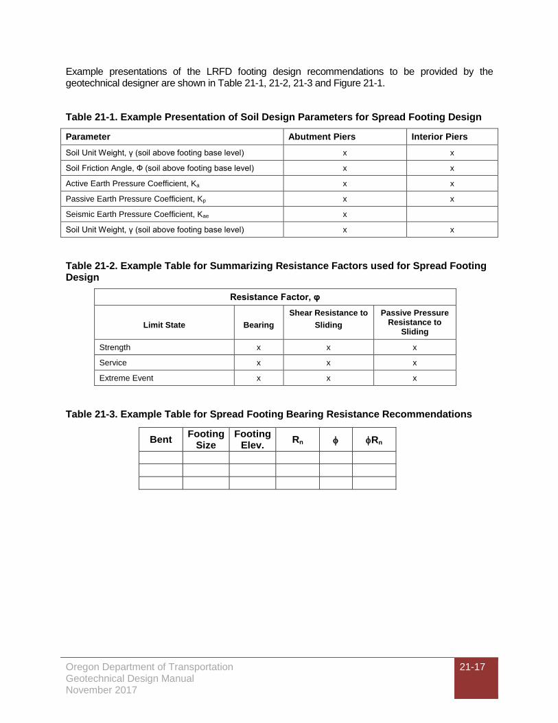
Example presentations of the LRFD footing design recommendations to be provided by the geotechnical designer are shown in Table 21-1, 21-2, 21-3 and Figure 21-1.
Table 21-1. Example Presentation of Soil Design Parameters for Spread Footing Design
Parameter Abutment Piers Interior Piers Soil Unit Weight, γ (soil above footing base level) x x
Soil Friction Angle, Ф (soil above footing base level) x x
Active Earth Pressure Coefficient, Ka x x
Passive Earth Pressure Coefficient, Kp x x
Seismic Earth Pressure Coefficient, Kae x
Soil Unit Weight, γ (soil above footing base level) x x
Table 21-2. Example Table for Summarizing Resistance Factors used for Spread Footing Design
Resistance Factor, φ
Limit State
Bearing Shear Resistance to
Sliding Passive Pressure
Resistance to Sliding
Strength x x x
Service x x x
Extreme Event x x x
Table 21-3. Example Table for Spread Footing Bearing Resistance Recommendations
Bent Footing Size
Footing Elev. Rn φ φRn
Oregon Department of Transportation Geotechnical Design Manual November 2017
21-18
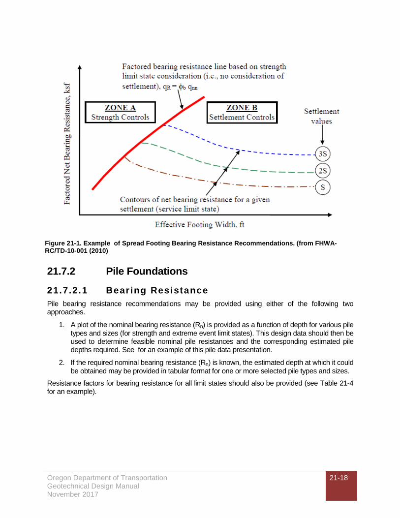
21.7.2 Pile Foundations
Bearing Resistance 21.7.2.1Pile bearing resistance recommendations may be provided using either of the following two approaches.
1. A plot of the nominal bearing resistance (Rn) is provided as a function of depth for various pile types and sizes (for strength and extreme event limit states). This design data should then be used to determine feasible nominal pile resistances and the corresponding estimated pile depths required. See for an example of this pile data presentation.
2. If the required nominal bearing resistance (Rn) is known, the estimated depth at which it could be obtained may be provided in tabular format for one or more selected pile types and sizes.
Resistance factors for bearing resistance for all limit states should also be provided (see Table 21-4 for an example).
Figure 21-1. Example of Spread Footing Bearing Resistance Recommendations. (from FHWA-RC/TD-10-001 (2010)

Oregon Department of Transportation Geotechnical Design Manual November 2017
21-19
Table 21-4. Example Table of Resistance Factors for Pile Design.
Resistance Factor, φ
Limit State Bearing
Resistance Uplift
Strength x x
Service x x
Extreme Event x x
Once Rn is known (or the total driving resistance, Rndr, if applicable) and the cutoff elevation of the pile is obtained from the bridge designer, then the “Engineers Estimated Length” can be determined for steel piles. The Engineer’s Estimated Lengths are required in the project special provisions for each bridge bent. Table 21-5 below is as example of how this information should be presented. The table should be modified as necessary to account for reduced capacities due to scour, liquefaction, downdrag or other conditions.
Figure 21-2. Example Plots of Pile Bearing and Uplift Resistance.

Oregon Department of Transportation Geotechnical Design Manual November 2017
21-20
Table 21-5. Pile Resistances & Estimated Lengths (Br. 12345)
Pile Type: PP16x0.50”
Bent Rn
(kips) ϕRn
(kips)
C.O. Elev. (ft.)
Est. Tip Elev. (ft.)
Engr’s Est. Length, (ft.)
Req’d. Tip Elev. (ft.)
1 450 180 210 130 80 150
350 140 210 145 65 150
2 450 180 170 120 50 135
350 140 170 130 40 135
3 450 180 200 125 75 140
350 140 200 135 65 140
Legend & Table Notes:
Rn = Nominal pile bearing resistance
ϕRn = Factored pile bearing resistance, (ϕ based on field method used to determine the required nominal pile bearing resistance)
C.O. = Pile cutoff elevation
Downdrag 21.7.2.2If downdrag loads are estimated, the following should be provided:
• XXX downdrag load, DD,
• Depth of the downdrag zone, or thickness of the downdrag layer,
• Downdrag load factor,
• Cause of the downdrag (settlement due to vertical stress increase, liquefaction, etc.),
• Also the total driving resistance, Rndr, (the required nominal pile driving resistance), taking into account the downdrag loads, should be provided.
Scour 21.7.2.3If scour is predicted, the depth of scour and the skin friction lost due to scour, Rscour, should be provided. The total driving resistance, Rndr, (the required nominal resistance), taking the loss of friction due to scour into account, should be provided.
Upl i f t Resistance 21.7.2.4For evaluating uplift, the geotechnical designer should provide the following:
• Nominal (un-factored) and factored uplift resistance, Rn, either plotted as a function of depth or as a single value for a given minimum tip elevation, depending on the project needs.,
• Skin friction lost, due to scour or liquefaction that is to be applied to the uplift resistance curves, (provided either separately, in tabular form, or include on plots of uplift resistance with depth),
• Resistance factors for either single piles or pile groups (as appropriate).

Oregon Department of Transportation Geotechnical Design Manual November 2017
21-21
Lateral Resistance 21.7.2.5The geotechnical designer should provide the soil parameters necessary to develop p-y curves and perform the lateral load analysis. The p-y curve soil input data should be provided for each soil or rock unit as defined by the top and bottom elevations of each unit. Resistance factors for lateral load analysis do not need to be provided, as the lateral load resistance factors will typically be 1.0.
The parameters required are typically those required for the LPile, GROUP or DFSAP proprietary computer programs and the p-y soil/rock parameters provided should be in a format for easy insertion into either of these computer programs. Coordinate with the structural design as necessary to determine which program input values are required. The LPile, GROUP or DFSAP User Manuals should be referenced for more information. It is important that the geotechnical designer maintain good communication with the structural designer to determine the kind of soil parameters necessary for the lateral load analysis of the structure. If liquefaction of foundation soils is predicted, soil parameters should be provided for both the liquefied and non-liquefied soil conditions. Table 21-6 is an example format for presenting the required data for a non-liquefied soil condition.
Table 21-6 Soil Parameters for Lateral Load Analysis (non-liquefied soil condition). Bridge 12345; Bents 1 & 3
ELEVATION (ft.) From To
p-y Curve Model*
K (lbs./in3)
SOIL PARAMETERS γ,(pci) c,(psi) e50 ϕ
SOIL DESCRIPTION
63.5 55.0 Soft Clay 500 0.06 3.5 .007 -- Sandy Clayey Silt to Silty Clay (fill)
55.0 30.0 Stiff clay
without free water
1000 0.07 13 .005 -- Silt w/ trace sand & clay to Clayey Silt, low plasticity
30.0 10.0 Stiff clay
without free water
2000 0.072 20 .004 -- Clay to Silty Clay, med.-high plasticity, very stiff
* For the LPile program provide the appropriate soil type from the default types listed in LPile or provide custom P-y curves if necessary.
If lateral loads imposed by special soil loading conditions such as landslide forces are present, the XXX lateral soil force or stress distribution, and the load factors to be applied to that force or stress, should be provided.
Required Pi le Tip Elevation for Minimum 21.7.2.6Penetration
Provide a required pile tip elevation for piles at each bent. The required tip elevation represents the highest acceptable tip elevation that will still provide the required resistances and performance under all loading conditions. The required tip elevation (sometimes referred to as “Minimum Tip Elevation”) is typically based on one or more of the following conditions:
• Pile tip reaching the required bearing layer or depth,
• Providing required uplift resistance,
• Providing required embedment for lateral support,
• Satisfying settlement and/or downdrag criteria,
• Providing sufficient embedment below scour depths or liquefiable layers.

Oregon Department of Transportation Geotechnical Design Manual November 2017
21-22
The required pile tip elevations provided in the Geotechnical Report may need to be adjusted depending on the results of the lateral load or uplift load evaluation performed by the structural designer. If adjustments in the required tip elevations are necessary, or if changes in the pile diameter are necessary, the geotechnical designer should be informed so that pile drivability and resistance recommendations can be re-evaluated. The required tip elevation may require driving into, or through, very dense soil layers resulting in potentially high driving stresses. Under these conditions a wave equation drivability analysis is necessary to make sure the piles can be driven to the required embedment depth (tip elevation) without damage.
Pi le Tip Reinforcement 21.7.2.7Specify steel pile tip reinforcement if piles are to be driven through very dense granular soils containing cobbles and boulders or for penetration into weak rock. Pile points (H-piles) or shoes (pipe piles) are typically specified. In pipe pile driving conditions where difficult driving through dense sand and gravel is anticipated before reaching the required tip elevation, inside-fit pipe pile shoes are sometimes used to help retard the formation of a soil plug at the pile tip. Section 02520 of the Standard Special Provisions must be included in the project specifications for specifying the proper steel grade for pile tip reinforcement and other requirements. Also note that outside-fit pile tip reinforcement (points or shoes) can reduce the friction resistance and this effect should be taken into account in design before specifying outside fit tips or shoes.
Pi le Spl ices 21.7.2.8Provide the number of anticipated pile splices that might be needed due to variability of the subsurface conditions. This number of splices should be included as a bid item in the contract documents. ODOT pays for splices when piles have to be driven a certain length over the Engineer’s Estimated Length. Refer to “ODOT Standard Specification 00520” for the criteria used to determine measurement and payment for pile splices.
Pi le Driving Cri ter ia and Acceptance 21.7.2.9The method of construction control and pile acceptance must be specified in the report for each project. All piles should be accepted based on field measured pile driving resistances, established by the FHWA dynamic formula, wave equation analysis, PDA/signal matching methods or static load test criteria. ODOT typically uses the dynamic formula or wave equation method for most projects.
The pile driving analyzer (PDA) with signal matching (CAPWAP) is also sometimes used on projects where it is economically justified. Full scale static load tests are rarely performed but are recommended for large projects where there is potential for substantial savings in foundation costs.
Typical ODOT practices regarding the use of dynamic driven pile acceptance methods are described as follows:
FHWA Gates Equation: For routine pile design projects with nominal pile bearing resistances less than or equal to 600 kips, the default dynamic formula used to establish pile driving criteria is the FHWA Gates Equation. When using this equation a resistance factor of 0.40 is applied to the nominal bearing resistance to determine the factored resistance. Wave Equation Analysis Program (WEAP): Wave Equation driving criteria is generally used for the following situations:
• Nominal pile resistances greater than of 600 kips,
• Where driving stresses are a concern (e.g., short end-bearing piles or required penetration through very dense strata),

Oregon Department of Transportation Geotechnical Design Manual November 2017
21-23
• Very long friction piles in granular soils.
A resistance factor of 0.50 is applied to the nominal bearing resistance to determine the factored resistance. When the wave equation method is specified, the contractor is required to perform a wave equation analysis of the proposed hammer and driving system and submit the analysis as part of the hammer approval process. The soils input criteria necessary for the contractor to perform the WEAP analysis needs to be supplied in a table in Section 00520 of the contract special provisions. An example of a completed table that would be provided in the geotechnical report (and special provisions) is shown below.
Table 21-7. Example of Wave Equation Input Table. Bridge No. 12345; Bents 1 & 2
Pile Type Pile
Length (ft.)
Quake (in.) Damping (in./sec.)
Friction Distribution
(ITYS) IPRCS (Note 2)
Rn (kips)
Skin Toe Skin Toe PP16 x 0.50 85.0 0.10 0.15 0.20 0.20 Note 1 95 620
Note 1: Use a rectangular distribution of skin resistance over the portion of the pile underground. Note 2: IPRCS is the percent skin friction (percent of Rn that is skin friction in the WEAP analysis).
Refer to the “Standard Special Provisions for Section 00520” for additional specification requirements. Provide WEAP input data for the highest (worst-case) driving stress condition, which may not always be for the pile at the estimated tip elevation.
Pile Driving Analyzer (PDA) with Signal Matching: Large pile driving projects may warrant the use of dynamic pile testing using a pile driving analyzer for additional construction quality control and to save on pile lengths. Generally the most beneficial use of PDA testing is on projects with large numbers of very long, friction piles driven to high resistance. However, there may be other reasons for PDA testing such as high pile driving stress conditions, testing new pile hammers, questionable hammer performance or to better determine the pile skin friction available for uplift resistance. A resistance factor of 0.65 can be applied to the nominal bearing resistance determined by PDA and signal matching analysis if an adequate number of production piles are tested. AASHTO Article 10.5.5.2.3 should be referenced for the procedures to use for PDA/Signal Matching pile acceptance. A signal matching (CAPWAP) analysis of the dynamic test data should always be performed to determine the axial nominal resistance and to calibrate the PDA resistance prediction methods.. The piles should be tested after a waiting period if pile setup or relaxation is anticipated.
Special provisions for past PDA/CAPWAP projects are available on the ODOT “GEOSITE” on the scdata server (internal to ODOT only) at the following address:
\\Scdata\geosite\G-H Geotech Common\GEO-SPECIFICATIONS

Oregon Department of Transportation Geotechnical Design Manual November 2017
21-24
21.7.3 Drilled Shafts To evaluate bearing resistance, the geotechnical designer provides, as a function of depth and for various shaft diameters, the nominal bearing resistance for end bearing, Rp, and side friction, Rs, used to calculate Rn, for strength and extreme event limit state calculations (see example figures below). For the service limit state, the bearing resistance at a specified settlement, typically 0.5 or 1.0 inch (mobilized end bearing and mobilized side friction) should be provided as a function of depth and shaft diameter. See Figure 21-5 example of lateral earth pressures for gravity wall design for an example of the shaft bearing resistance information that should be provided. Resistance factors for bearing resistance for all limit states should also be provided.
Downdrag If downdrag loads are estimated, the following should be provided:
• The depth of the downdrag zone, or thickness of the downdrag layer,
• The XXX downdrag load, DD, as a function of shaft diameter,
• The downdrag load factor,
• The loss of skin friction due to downdrag,
• The cause of the downdrag (settlement due to vertical stress increase, liquefaction, etc.).
Scour 21.7.3.1If scour is predicted, the depth of scour and the skin friction lost due to scour, Rscour, should be provided.
Upl i f t Resistance 21.7.3.2For evaluating uplift, the geotechnical designer provides, as a function of depth, the nominal and factored uplift resistance. The skin friction lost due to scour or liquefaction that is to be applied to the uplift resistance curves also should be provided (either separately, in tabular form, or included on the plots of uplift resistance with depth). Resistance factors for either single shafts or shaft groups should also be provided (as appropriate).
Lateral Resistance 21.7.3.3Provide soil input values for the LPile, GROUP or DFSAP program as described in Section 21.7.2.5. Coordinate with the structural design as necessary to determine which program input values are required. Resistance factors for lateral load analysis generally do not need to be provided, as the lateral load resistance factors will typically be 1.0.

Oregon Department of Transportation Geotechnical Design Manual November 2017
21-25
Figure 21-3. Typical shaft bearing resistance plots (all limit states).
Crosshole Sonic Log Testing 21.7.3.4Access tubes for crosshole sonic log (CSL) testing are typically provided in all drilled shafts unless otherwise recommended by the geotechnical designer. Typically, one tube is provided per foot of shaft diameter with a minimum of 3 tubes provided per shaft. All CSL tubes should be Schedule 40 steel pipe conforming to the material properties specified in Section 00512, unless otherwise specified by special provision.
The amount of CSL testing needs to be determined for each project and should be provided in the special provisions (Section 00512.42). Specify the minimum number of CSL tests to be conducted and the location of these tests. The actual number of tests can be increased, if necessary, during construction depending on the contractor’s work performance. The amount of testing that should be performed depends on the subsurface conditions, the redundancy of the foundation system and the contractor’s work performance. The first shaft constructed is always tested to confirm the contractor’s construction procedures and workmanship. Subsequent tests should be based on the following guidelines and good engineering judgment:
• Test every single-shaft bent,
• Minimum of 1 CSL test per bent (or shaft group) or 1/10 shafts.
Also consider:
• Redundancy in the substructure/foundation,

Oregon Department of Transportation Geotechnical Design Manual November 2017
21-26
• Soil conditions (potential construction difficulties like caving soils, ground swelling, and boulders),
• Groundwater conditions (wet holes, artesian conditions).
See Chapter 18 for additional guidelines for CSL testing procedures during construction
Shaft Reinforcement Lengths in Rock Socket 21.7.3.5Appl ications
For rock socket shaft designs where the top of rock is uncertain (as described in Chapter 8), provide the following in the Geotechnical Report and in the project special provisions:
• The additional length(s) of shaft reinforcement needed to account for the uncertainty in the top of the bearing layer for rock socket applications,
• The requirement that the contractor’s drilled shaft equipment must be capable of drilling the full extra shaft length. This requirement must be included in the project Special Provisions.
Refer to the ODOT Standard Special Provisions for Section 00512 for further guidance and details
21.7.4 Geotechnical Report Checklist for Bridge Foundations
The Geotechnical Report Review Checklist in Appendix 21-A Geotechnical Report Review Checklist should be used to check the content and completeness of geotechnical reports prepared for bridge foundation projects. The checklist should be completed by the Professional-of-Record for the project. The checklist questions should be completed by referring to the contents of the geotechnical report. For each question, a yes, no, or not applicable (N/A) response should be provided. A response of "I don't know" to any applicable section on the checklist is not to be shown with a check in the "Not Applicable" (N/A) column. All checklist questions answered with “NO” should be fully explained.
A copy of the completed checklist, and all comments and explanations, should be included with the geotechnical report when submitted for review to ODOT.
21.7.5 Geotechnical Report Distribution Geotechnical reports are posted on eBIDS and should be distributed to the following personnel:
• Structure Designer
• Roadway Designer
• Specification Writer
• Project Leader
• Project Manager (more copies if requested for contractors)
• Hydraulic Engineer (if appropriate)
• Project Geologist

Oregon Department of Transportation Geotechnical Design Manual November 2017
21-27
21.7.6 Retaining Walls To evaluate bearing resistance for footing-supported gravity walls, the geotechnical designer provides qn, the nominal bearing resistance available, and qserv, the settlement limited bearing resistance for the specified settlement for various effective footing widths (i.e., reinforcement length plus facing width for MSE walls) likely to be used (see Figure 21-4). Resistance factors for each limit state are also provided. The amount of settlement on which qserv is based shall be stated. The calculations should assume that qn and qserv will resist uniform loads applied over effective footing dimension B’ (i.e., effective footing width (B - 2e)) as determined using the Meyerhof method for soil). For footings on rock, the calculations should assume that qn and qserv will resist peak loads and that the stress distribution is triangular or trapezoidal rather than uniform. The geotechnical designer also provides wall base embedment depth requirements or footing elevations to obtain the recommended bearing resistance.
To evaluate sliding stability, bearing, and eccentricity of gravity walls, the geotechnical designer provides:
• Resistance factors for both the strength and extreme event limit states for calculating the shear and passive resistance in sliding,
• Soil parameters φ, Kp, γ and depth of soil in front of footing to ignore when calculating passive resistance,
• Soil parameters φ, Ka, and γ used to calculate active force behind the wall,
• Coefficient of sliding, tanϕ,
• Seismic design parameters:
o Peak ground acceleration coefficient (PGA)
o Short period spectral acceleration coefficient (SS)
o Long period spectral acceleration coefficient (S1)
o Site class
o Peak ground acceleration coefficient modified by the zero period site factor (As)
o Horizontal seismic acceleration coefficient (kh)
o Seismic active pressure coefficient (KAE) – where Mononobe-Okabe method is suitable
o Dynamic active horizontal thrust, including static earth pressure (PAE) – where Mononobe-Okabe method is not suitable
• Separate earth pressure diagrams for strength and extreme event (seismic) limit state calculations that include all applicable earth pressures, with the exception of traffic barrier impact loads (traffic barrier impact loads are developed by the structural designer).
The geotechnical designer should evaluate overall stability. If overall stability controls the required wall width, the designer should provide the minimum footing or reinforcement length required to maintain an acceptable safety factor (1.5 for the strength and 1.1 for the extreme event limit states, which is the inverse of the resistance factor, i.e., 0.65 and 0.9, respectively).

Oregon Department of Transportation Geotechnical Design Manual November 2017
21-28
Figure 21-4. Example of bearing resistance recommendations for gravity walls
Figure 21-5. Example of lateral earth pressures for gravity wall design

Oregon Department of Transportation Geotechnical Design Manual November 2017
21-29
For non-proprietary MSE walls, the spacing, strength, and length of soil reinforcement should also be provided, as well as the applicable resistance factors. MSE reinforcement properties should be specified in the special provisions for Section 02320. Spacing and length requirements may also be best illustrated using typical cross sections.
For non-gravity cantilever walls and anchored walls, the following should be provided:
• XXXX bearing resistance of the soldier piles or drilled shafts as a function of depth (see Figure 21-3),
• Lateral earth pressure distribution (active and passive),
• Minimum embedment depth required for overall stability,
• No load zone dimensions,
• XXX anchor resistance for anchored walls, and the associated resistance factors.
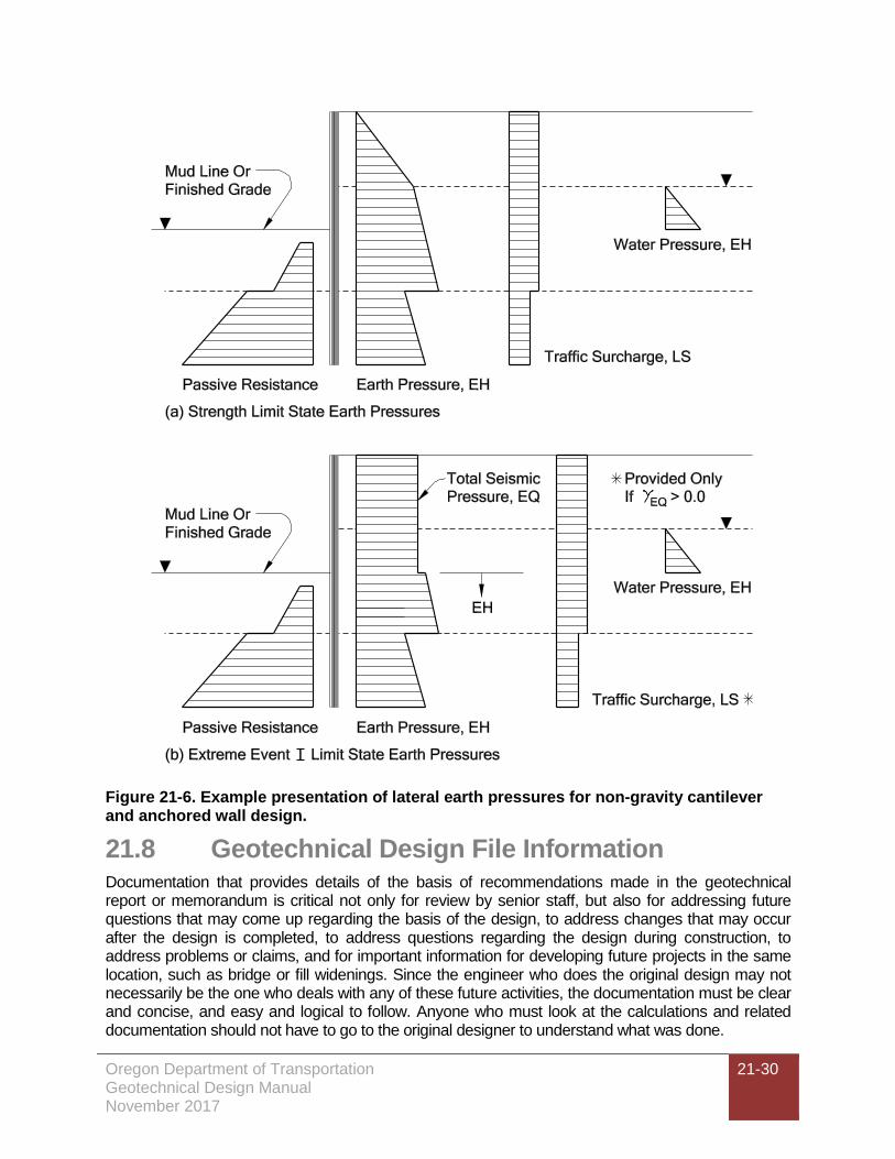
Table 21-8 and Figure 21-6 provides an example presentation of soil design parameters and earth pressure diagrams for non-gravity cantilever and anchored walls to be provided by the geotechnical designer.
Table 21-8. Example presentation of soil design parameters for design of non-gravity cantilever walls and anchored walls.
Parameter Value Soil Unit Weight, γ (all applicable strata) x Soil Friction Angle, Ф (all applicable strata)
x
Active Earth Pressure Coefficient, Ka x Passive Earth Pressure Coefficient, Kp x Seismic Earth Pressure Coefficient, Kae x Averaged γ used to determine Kae x Averaged Ф used to determine Kae x
Oregon Department of Transportation Geotechnical Design Manual November 2017
21-30
Figure 21-6. Example presentation of lateral earth pressures for non-gravity cantilever and anchored wall design.
21.8 Geotechnical Design File Information Documentation that provides details of the basis of recommendations made in the geotechnical report or memorandum is critical not only for review by senior staff, but also for addressing future questions that may come up regarding the basis of the design, to address changes that may occur after the design is completed, to address questions regarding the design during construction, to address problems or claims, and for important information for developing future projects in the same location, such as bridge or fill widenings. Since the engineer who does the original design may not necessarily be the one who deals with any of these future activities, the documentation must be clear and concise, and easy and logical to follow. Anyone who must look at the calculations and related documentation should not have to go to the original designer to understand what was done.

Oregon Department of Transportation Geotechnical Design Manual November 2017
21-31
The project documentation should be consistent with FHWA guidelines and as set forth in this chapter. Details regarding what this project documentation should contain are provided in the following sections.
21.8.1 Documentation for Preliminary Geotechnical Design
Document sources of information (including the date) used for the preliminary evaluation. Typical sources include as-built bridge or other structure drawings, as-constructed roadway drawings, existing test hole logs, geologic maps, previous or current geologic reconnaissance results or previous site investigation work and instrumentation data. Also document the following:
• If a geologic reconnaissance was conducted, the details of that site visit, including any photos taken, should be included in this documentation.
• For structures, provide a description of the foundation support used for the existing structure, including design bearing capacity, if known, and any foundation capacity records such as pile driving logs, load test results, etc.
• From the contract or maintenance records, summarize any known construction or maintenance problems encountered during construction or throughout the life of the structure. Examples from the construction records include over-excavation depth and extent, and why it was needed, seepage observed in cuts and excavations, dewatering problems, difficult digging, including obstructions encountered during excavation, obstructions encountered during foundation installation (e.g., for piles or shafts), slope instability during construction, changed conditions or change orders involving the geotechnical features of the project, and anything else that would affect the geotechnical aspects of the project.
• For any geotechnical recommendations made, summarize the logic and justification for those recommendations. If the recommendations are based on geotechnical engineering experience and judgment, describe what specific information led to the recommendation(s) made.
21.8.2 Documentation for Final Geotechnical Design In addition to the information described above in Section 21.7.1, the following information should be documented in the project geotechnical file:
1. List or describe all given information and assumptions used, as well as the source of that information. For all calculations, an idealized design cross-section that shows the design element (e.g., wall, footing, pile foundation, buttress, rock slope, etc.) located in context to the existing and proposed ground lines, and the foundation soil/rock should be provided. This idealized cross-section should show the soil/rock properties used for design, the soil/rock layer descriptions and thicknesses, the water table location, the existing and proposed ground line, and any other pertinent information. For slope stability, the soil/rock properties used for the design should be shown (neatly handwritten, if necessary) on the computer generated output cross-section.
2. Additional information and/or a narrative should also be provided which describes the basis for the design soil/rock properties used. If the properties are from laboratory tests, state where the test results, and the analysis of those test results, can be found in the final geotechnical design documentation and how those test results apply to the specific site conditions and strata encountered including consideration of site geological history. If using

Oregon Department of Transportation Geotechnical Design Manual November 2017
21-32
correlations to SPT, cone data or other measurements, state which correlations were used, the range of applicability of the correlation to the available measurements, the potential uncertainty in the estimated property value due to the use of that correlation and any corrections to the data made,
3. The design method(s) used must also be clearly identified for each set of calculations, including any assumptions used to simplify the calculations, if that was done, or to determine input values for variables in the design equation. Write down equation(s) used and the meaning of the terms used in equation(s), or reference where equation(s) used and/or meaning of terms were obtained. Attach a copy of all curves or tables used in making the calculations and their source, or appropriately reference those tables or figures. Write down or summarize all steps needed to solve the equations and to obtain the desired solution.
4. If using computer spreadsheets, provide detailed calculations for one example to demonstrate the basis of the spreadsheet and that the spreadsheet is providing accurate results. Hand calculations are not required for well proven, well documented programs such as XSTABL, SLOPE/W, SHAKE2000 or GRLWEAP. Detailed example calculations that illustrate the basis of the spreadsheet are important for engineering review purposes and for future reference if someone needs to get into the calculations at some time in the future. A computer spreadsheet in itself is not a substitute for that information.
5. Highlight the solutions that form the basis of the engineering recommendations to be found in the project geotechnical report so that they are easy to find. Be sure to write down which locations or piers where the calculations and their results are applicable.
6. Provide a results summary, including a sketch of the final design, if appropriate.
Each set of calculations (for each structure) should be sealed and dated by the professional-of-record. If the designer is not registered, the reviewer should seal and date the calculations. Consecutive page numbers should be provided for each set of calculations and each page should be initialed by the reviewer.
A copy of the appropriate portion of the FHWA checklist for geotechnical reports (i.e., appropriate to the project) should be included with the calculations and filled out as appropriate. This checklist will aid the reviewer regarding what was considered in the design and to help demonstrate consistency with the FHWA guidelines.
21.8.3 Geotechnical File Contents The geotechnical project file(s) should contain the information necessary for future users of the file to understand the historical geotechnical data available and all the geotechnical work that was performed as part of this project. This would include the scope of the project, the dimensions and locations of the project features, the geotechnical investigation plan, field and laboratory testing and results, the geotechnical design work performed and design recommendations.
Two types of project files should be maintained: 1) the geotechnical design file(s), and 2) the construction support file(s).
The geotechnical design file should specifically contain the following information:
• Historical project geotechnical;
• As-built data and historical geotechnical information related to, the project;
• Geotechnical investigation plan development documents;

Oregon Department of Transportation Geotechnical Design Manual November 2017
21-33
• Geologic reconnaissance results;
• Cross-sections, structure layouts, etc., that demonstrate the scope of the project and project feature geometry as understood at the time of the final design, if such data is not contained in the geotechnical report;
• Information that illustrates design constraints, such as right-of-way location, location of critical utilities, wetlands and location and type of adjacent facilities that could be affected by the design;
• Boring log field notes;
• Boring logs;
• Field test results, (CPT, pressure meter, vane shear, shear wave measurements);
• Laboratory test results, including rock core photos and records;
• Field instrumentation measurements;
• Final calculations only, unless preliminary calculations are needed to show design development;
• Final wave equation runs for pile foundation constructability evaluation;
• Key photos (must be identified as to the subject and locations), including CD with photo files;
• Key correspondence (including e-mail) that tracks the development of the project and contains information regarding design changes or geotechnical recommendations. This does not include general correspondence that is focused on project coordination activities.
The geotechnical construction file should contain the following information (as applicable):
• Pile hammer approval letter with driving criteria including wave equation analysis;
• Construction submittal reviews (retain temporarily only, until it is clear that there will be no construction claims);
• PDA/CAPWAP results;
• Embankment or other instrumentation monitoring data;
• Change order correspondence and calculations;
• Documentation of any changes to the original geotechnical design or specifications;
• Claims-related correspondence and data;
• Photos (must be identified as to the subject and locations), including CD with photo files;
• CSL reports and any correspondence concerning shaft defects, repair work and the approval of drilled shafts.

Oregon Department of Transportation Geotechnical Design Manual November 2017
21-34
Consul tant Geotechnical Reports and 21.8.3.1Documents Produced For ODOT
Geotechnical reports and documents produced by geotechnical consultants (including geotechnical work performed for Design-Build projects) shall be subject to the same reporting and documentation requirements as those produced by ODOT staff, as described in this chapter. The detailed analyses and/or calculations produced by the consultant in support of the geotechnical report development shall be provided to ODOT.
21.9 References Section intentionally blank.

Oregon Department of Transportation Geotechnical Design Manual November 2017
21-A-1
Appendix 21-A Geotechnical Report Review Checklist (Structure Foundations Supplement)
YES NO N/A1 Title/Cover Page
1.1 Heading “Geotechnical Report” in larger letters1.2 Bridge Name1.3 Bridge Number1.4 Section Name1.5 Highway & Milepoint1.6 County1.7 Key Number1.8 Date
2 Table of Contents3 Detailed Vicinity Map4 Body of Report
4.1 Introduction4.1.1. Is project scope and purpose summarized?4.1.2 Is a concise description given for the general geologic setting and topography of the area?
4.2 Office Research4.2.1 Summary of all pertinent records and other information that relate to foundation design and construction.
4.3 Subsurface Explorations and Conditions4.3.1 Is a summary of the field explorations, locations, and testing given?4.3.2 Is a description of general subsurface soil and rock conditions given?4.3.3 Is the groundwater condition given?
4.4 Laboratory Data4.4.1 Are laboratory test results (e.g., natural moisture, Atterberg Limits, consolidation,
shear strengths, etc.) discussed and summarized in the report?4.5 Summarize Hydraulics Information that affects foundation recommendations
4.5.1 Bridge options providing required waterway4.5.2. 100 and 500-year scour depths and elevations4.5.3. Riprap protection; class, depth, and extent
4.6 Seismic Analysis and Evaluation4.6.1 Bedrock acceleration coefficients (500 & 1000-yr) and AASHTO soil profile type4.6.2 Liquefaction analysis and bridge access & performance assessment (settlement, stability, lateral deformation)4.6.3 Liquefaction Mitigation recommended?
4.6.3.1. Mitigation design, specifications and cost estimates supplied?4.7 Foundation Analyses and Design Recommendations
4.7.1 Foundation Options and Discussion4.7.2 Pile Foundations
4.7.2.1. Type (steel pipe, H-pile, concrete, displacement/friction or end-bearing)4.7.2.2. Material specification (e.g., ASTM & steel grade), size (e.g.,O.D. and thickness) 4.7.2.3. Tip treatment; open or closed-ended, tip protection required4.7.2.4. Ultimate nominal resistance, estimated cutoff elevation, estimated tip elevation. “estimated” or “order” length and
minimum required tip elevation.4.7.2.5. Axial factored resistance and resistance factor4.7.2.6. Nominal and factored uplift resistances4.7.2.7. Lateral resistance
4.7.2.6.1. Soil parameters for LPILE or COM624P analysis (e.g., p-y data, liquefied & nonliquefied soil conditions)4.7.2.8. Pile group settlement addressed?4.7.2.9. Downdrag potential addressed?
4.7.2.8.1. Provide downdrag loads, load factors and discussion of how downdrag loads are accounted for or mitigated?4.7.2.10. Reduced pile resistances (axial, uplift, lateral, etc) as a result of liquefaction, scour or downdrag4.7.2.11. Driving Criteria and Driveability Analysis
4.7.2.10.1. Dynamic equation where driveability or driving stress problems are not expected4.7.2.10.2. Wave Equation for nominal resistances greater than 540 kips or expected driving stress problems.
4.7.2.12. Static or dynamic load testing4.7.2.11.1 Are specifications provided describing how the tests are conducted and clearly defining all responsiblities?
4.7.3. Drilled Shafts4.7.3.1. Shaft type (i.e., end-bearing, friction or combination)4.7.3.2. Nominal axial resistance provided for various diameters and lengths (depths or tip elevs.)4.7.3.3. Rock socket lengths specified (and/or shaft tip elevations)4.7.3.4. Estimates of shaft settlement with depth under unfactored (service) load conditions.4.7.3.5. Resistance factors and factored resistances.4.7.3.6. Shaft group effects addressed?4.7.3.7 Lateral capacity addressed?
4.7.3.7.1. Soil parameters for COM624P or LPILE analysis provided (e.g., p-y data, liquefied & nonliquefied soil conditions)4.7.3.8 Static or dynamic load testing required?
4.7.3.8.1 Are specifications provided describing how the tests are conducted and clearly defining all responsiblities?4.7.4. Spread Footings
4.7.4.1. Description and properties of the anticipated foundation soil or rock4.7.4.2. Nominal bearing resistance as function of effective footing width4.7.4.3. Nominal bearing resistance for a given settlement (service limit state)4.7.4.4 Resistance factors and factored bearing resistance for strength and extreme limit states4.7.4.5. Recommended maximum elevation for base of footing4.7.4.6. Soil parameters for sliding and eccentricity provided? 4.7.4.7. Overall stability checked?
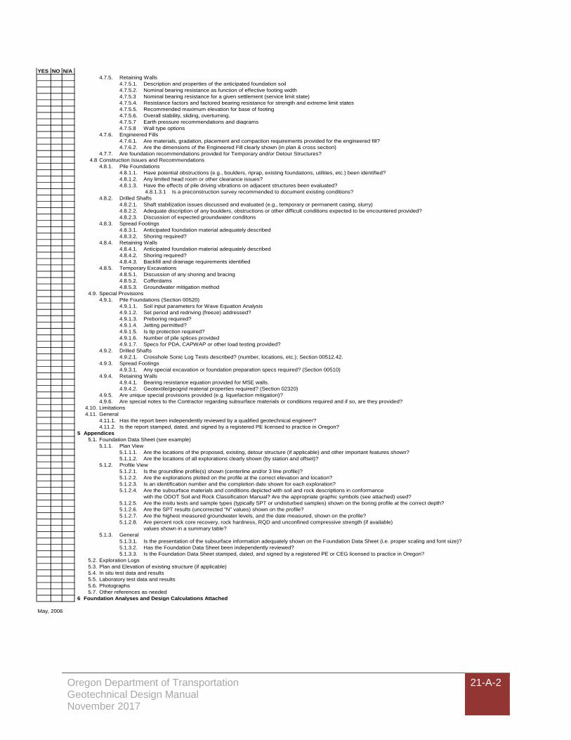
Oregon Department of Transportation Geotechnical Design Manual November 2017
21-A-2
YES NO N/A4.7.5. Retaining Walls
4.7.5.1. Description and properties of the anticipated foundation soil4.7.5.2. Nominal bearing resistance as function of effective footing width 4.7.5.3 Nominal bearing resistance for a given settlement (service limit state)4.7.5.4. Resistance factors and factored bearing resistance for strength and extreme limit states4.7.5.5. Recommended maximum elevation for base of footing4.7.5.6. Overall stability, sliding, overturning.4.7.5.7 Earth pressure recommendations and diagrams4.7.5.8 Wall type options
4.7.6. Engineered Fills4.7.6.1. Are materials, gradation, placement and compaction requirements provided for the engineered fill?4.7.6.2. Are the dimensions of the Engineered Fill clearly shown (in plan & cross section)
4.7.7. Are foundation recommendations provided for Temporary and/or Detour Structures?4.8 Construction Issues and Recommendations
4.8.1. Pile Foundations4.8.1.1. Have potential obstructions (e.g., boulders, riprap, existing foundations, utilities, etc.) been identified?4.8.1.2. Any limited head room or other clearance issues?4.8.1.3. Have the effects of pile driving vibrations on adjacent structures been evaluated?
4.8.1.3.1 Is a preconstruction survey recommended to document existing conditions?4.8.2. Drilled Shafts
4.8.2.1. Shaft stabilization issues discussed and evaluated (e.g., temporary or permanent casing, slurry)4.8.2.2. Adequate discription of any boulders, obstructions or other difficult conditions expected to be encountered provided?4.8.2.3. Discussion of expected groundwater conditons
4.8.3. Spread Footings4.8.3.1. Anticipated foundation material adequately described4.8.3.2. Shoring required?
4.8.4. Retaining Walls4.8.4.1. Anticipated foundation material adequately described4.8.4.2. Shoring required?4.8.4.3. Backfill and drainage requirements identified
4.8.5. Temporary Excavations4.8.5.1. Discussion of any shoring and bracing4.8.5.2. Cofferdams4.8.5.3. Groundwater mitigation method
4.9. Special Provisions4.9.1. Pile Foundations (Section 00520)
4.9.1.1. Soil input parameters for Wave Equation Analysis4.9.1.2. Set period and redriving (freeze) addressed?4.9.1.3. Preboring required?4.9.1.4. Jetting permitted?4.9.1.5. Is tip protection required?4.9.1.6. Number of pile splices provided4.9.1.7. Specs for PDA, CAPWAP or other load testing provided?
4.9.2. Drilled Shafts4.9.2.1. Crosshole Sonic Log Tests described? (number, locations, etc.); Section 00512.42.
4.9.3. Spread Footings4.9.3.1. Any special excavation or foundation preparation specs required? (Section 00510)
4.9.4. Retaining Walls4.9.4.1. Bearing resistance equation provided for MSE walls.4.9.4.2. Geotextile/geogrid material properties required? (Section 02320)
4.9.5. Are unique special provisions provided (e.g. liquefaction mitigation)?4.9.6. Are special notes to the Contractor regarding subsurface materials or conditions required and if so, are they provided?
4.10. Limitations4.11. General
4.11.1. Has the report been independently reviewed by a qualified geotechnical engineer?4.11.2. Is the report stamped, dated, and signed by a registered PE licensed to practice in Oregon?
5 Appendices5.1. Foundation Data Sheet (see example)
5.1.1. Plan View5.1.1.1. Are the locations of the proposed, existing, detour structure (if applicable) and other important features shown?5.1.1.2. Are the locations of all explorations clearly shown (by station and offset)?
5.1.2. Profile View5.1.2.1. Is the groundline profile(s) shown (centerline and/or 3 line profile)?5.1.2.2. Are the explorations plotted on the profile at the correct elevation and location?5.1.2.3. Is an identification number and the completion date shown for each exploration?5.1.2.4. Are the subsurface materials and conditions depicted with soil and rock descriptions in conformance
with the ODOT Soil and Rock Classification Manual? Are the appropriate graphic symbols (see attached) used?5.1.2.5. Are the insitu tests and sample types (typically SPT or undisturbed samples) shown on the boring profile at the correct depth?5.1.2.6. Are the SPT results (uncorrected “N” values) shown on the profile?5.1.2.7. Are the highest measured groundwater levels, and the date measured, shown on the profile?5.1.2.8. Are percent rock core recovery, rock hardness, RQD and unconfined compressive strength (if available)
values shown in a summary table?5.1.3. General
5.1.3.1. Is the presentation of the subsurface information adequately shown on the Foundation Data Sheet (i.e. proper scaling and font size)?5.1.3.2. Has the Foundation Data Sheet been independently reviewed?5.1.3.3. Is the Foundation Data Sheet stamped, dated, and signed by a registered PE or CEG licensed to practice in Oregon?
5.2. Exploration Logs5.3. Plan and Elevation of existing structure (if applicable)5.4. In situ test data and results5.5. Laboratory test data and results5.6. Photographs5.7. Other references as needed
6 Foundation Analyses and Design Calculations Attached
May, 2006