in s t r u c t io n m a n u a l - webpages.uncc.edujdbowen/4090/2007/arm... · s a f e t y in t h e...
TRANSCRIPT

INSTRUCTION MANUAL
C4
MULTI PURPOSE TEACHING FLUME
C4
ISSUE 13 SEPTEMBER 2005


ARMFIELD LIMITED OPERATING INSTRUCTIONS AND EXPERIMENTS
C4
PAGE NO.
SAFETY IN THE USE OF EQUIPMENT SUPPLIED BY ARMFIELD 1
INTRODUCTION 5
RECEIPT OF EQUIPMENT 6
DESCRIPTION 7
INSTALLATION REQUIREMENTS 10
ASSEMBLY 11
CONNECTION TO SERVICES 15
COMMISSIONING 17
ROUTINE MAINTENANCE 20
MODELS AVAILABLE FOR USE IN THE C4 FLUME 25
GENERAL ASSEMBLY INSTRUCTIONS FOR MODELS 27
INDEX TO EXPERIMENTS 30
GENERAL SAFETY RULES a


SAFETY IN THE USE OF EQUIPMENT SUPPLIED BY ARMFIELD
Before proceeding to install, commission or operate the equipment described in this instruction manual we wish to alert you to potential hazards so that they may be avoided.
Although designed for safe operation, any laboratory equipment may involve processes or procedures which are potentially hazardous. The major potential hazards associated with this particular equipment are listed below.
. INJURY THROUGH MISUSE
. INJURY FROM ELECTRIC SHOCK
. INJURY FROM HANDLING LARGE OR HEA VY COMPONENTS
. RISK OF INFECTION DUE TO LACK OF CLEANLINESS
Accidents can be avoided provided that equipment is regularly maintained and staff and students are made aware of potential hazards. A list of general safety rules is included in this manual, to assist staff and students in this regard. The list is not intended to be fully comprehensive but for guidance only.
Please refer to the notes overleaf regarding the Control of Substances Hazardous to Health Regulations.
1

The COSHH Regulations
The Control of Substances Hazardous to Health Regulations (1988)
The COSHH regulations impose a duty on employers to protect employees and others from substances used at work which may be hazardous to health. The regulations require you to make an assessment of all operations which are liable to expose any person to hazardous solids, liquids, dusts, vapours, gases or micro-organisms. You are also required to introduce suitable procedures for handling these substances and keep appropriate records.
Since the equipment supplied by Armfield Limited may involve the use of substances which can be hazardous (for example, cleaning fluids used for maintenance or chemicals used for particular demonstrations) it is essential that the laboratory supervisor or some other person in authority is responsible for implementing the COSHH regulations.
Part of the above regulations is to ensure that the relevant Health and Safety Data Sheets are available for all hazardous substances used in the laboratory. Any person using a hazardous substance must be informed of the following:
Physical data about the substance
Any hazard from fire or explosion
Any hazard to health
Appropriate First Aid treatment
Any hazard from reaction with other substances
How to clean/ dispose of spillage
Appropriate protective measures
Appropriate storage and handling
Although these regulations may not be applicable in your country, it is strongly recommended that a similar approach be adopted for the protection of the students operating the equipment. Local regulations must also be considered.
Water-Borne Infections
The equipment described in this instruction manual involves the use of water which under certain conditions can create a health hazard due to infection by harmful micro-organisms.
2

For example, the microscopic bacterium called Legionella pneumophila will feed on any scale, rust, algae or sludge in water and will breed rapidly if the temperature of water is between 20 and 450C. Any water containing this bacterium which is sprayed or splashed creating air-borne droplets can produce a form of pneumonia called Legionnaires Disease which is potentially fatal.
Legionella is not the only harmful micro-organism which can infect water, but it serves as a useful example of the need for cleanliness.
Under the COSHH regulations, the following precautions must be observed:-
Any water contained within the product must not be allowed to stagnate, ie. the water must be changed regularly.
Any rust, sludge, scale or algae on which micro-organisms can feed must be removed regularly, ie. the equipment must be cleaned regularly.
Where practicable the water should be maintained at a temperature below 200C or above 450C. If this is not practicable then the water should be disinfected if it is safe and appropriate to do so. Note that other hazards may exist in the handling of biocides used to disinfect the water.
A scheme should be prepared for preventing or controlling the risk incorporating all of the actions listed above.
Further details on preventing infection are contained in the publication "The Control of Legionellosis including Legionnaires Disease" - Health and Safety Series booklet HS (G) 70.
3

USE OF A RESIDUAL CURRENT DEVICE FOR ELECTRICAL SAFETY
The equipment described in this Instruction Manual operates from a mains voltage electrical supply. The equipment is designed and manufactured in accordance with appropriate regulations relating to the use of electricity. Similarly, it is assumed that regulations applying to the operation of electrical equipment are observed by the end user.
However, to give increased operator protection, Armfield Ltd have incorporated a Residual Current Device or RCD (alternatively called an Earth Leakage Circuit Breaker - ELCB) as an integral part of this equipment. If through misuse or accident the equipment becomes electrically dangerous, an ReD will switch off the electrical supply and reduce the severity of any electric shock received by an operator to a level which, under normal circumstances, will not cause injury to that person.
At least once each month, check that the RCD is operating correctly by pressing the TEST button. The circuit breaker MUST trip when the button is pressed. Failure to trip means that the operator is not protected and the equipment must be checked and repaired by a competent electrician before it is used.
4

INTRODUCTION
This instruction manual provides the operating instructions and suggested experimental procedures for the C4 Multi Purpose Teaching Flume. The flume is supplied with a 2.5 metre long or a 5.0 metre long working section as required. A set of basic models is included with either version of the flume. A
range of optional models is also available. Details are given later in this instruction manual.
When studying Hydraulics, the fundamental concepts of energy and momentum are sometimes difficult to grasp, particularly where free surface flow is concerned. The Armfield Multi Purpose Teaching Flume has been developed to assist the student to overcome this difficulty. It provides a basic but nonetheless comprehensive facility for student experiments in open channel flow.
Although small in comparison with the majority of flumes, the dimensions of the working section have been sized so that the various phenomena may be clearly seen and reasonably accurate results may be obtained from measurements taken.
The flume includes a service module which stores water for recirculation making the unit self contained, except for the provision of an electrical supply. The construction allows for easy disassembly if at a later date it is required to move the unit to a different location.
The early part of this manual describes the flume, the models supplied as standard and models available as optional accessories. Full details on assembly, commissioning and routine maintenance are also included.
Experimental sheets are included which detail some of the demonstrations and exercises which can be performed using the flume and models. We wish to emphasise that these experiments do not exhaust the potential of the flume or the models. There are many further investigations that an imaginative user can devise and the user can construct alternative models for installation in the flume.
5
RECEIPT OF EQUIPMENT
1. SALES IN THE UNITED KINGDOM
The apparatus should be carefully unpacked and the components checked against the Advice Note. A copy of the Advice Note is supplied with this instruction manual for reference.
Any omissions or breakages should be notified to Armfield Ltd within three days of receipt.
2. SALES OVERSEAS
The apparatus should be carefully unpacked and the components checked against the Advice Note. A copy of the Advice Note is supplied with this instruction manual for reference.
Any omissions or breakages should be notified immediately to the Insurance Agent stated on the Insurance Certificate if the goods were insured by Armfield Ltd.
Your own insurers should be notified immediately if insurance was arranged by yourselves.
6

DESCRIPTION
All numerical references refer to the diagram on page 9.
The flume comprises a rectangular section of channel (1) with inlet (6) and discharge (7) tanks, which is supported by a pair of rigid pedestals. A service module (2) incorporating a sump tank and submersible pump provides a
source of water which is continuously recirculated through the channel section making the unit self contained, except for the provision of an electrical supply.
The working section of the channel, which is open at the top, consists of clear acrylic sides which are bonded to a bed fabricated from painted aluminium alloy. The end tanks are constructed from glass reinforced plastic (GRP) with a smooth gel coat on the inside. Water enters the parallel working section via an inlet tank (6). The water pipe entering the inlet tank has diffused outlets and is covered by a perforated plate and glass marbles. The sides of the inlet tank are profiled with a smooth contraction towards the working section. The combined action of these features is to reduce the turbulence of the water entering the inlet tank and to produce a smooth flow of water into the working section of the channel.
The level in the working section of the flume may be controlled by an overshot weir arrangement at the exit consisting of stop logs in a slot. Stop logs are simply added or taken away to provide the required depth of water in the working section. Water exiting from the channel enters the discharge tank (7) where it returns by gravity to the service module (2).
The service module is constructed from GRP. Water is drawn from a sump tank in the base of the service unit by a submersible pump. The water is
delivered to the flume via a shunt type flowmeter (5) and flow control valve (4). The flowmeter consists of a variable area flowmeter which is shunted across an orifice plate. This provides a direct reading of the volume flowrate of the water passing through the working section.
Water returns from the flume discharge tank to a moulded channel on the top of the service module. The water then flows over a weir carrier and into a
volumetric tank before returning to the sump tank under gravity. The weir carrier and volumetric tank provide alternative means (and demonstrations) of measuring the flow of water through the flume. A vee or rectangular notch weir can be installed in the weir carrier and a hook and point gauge (8) is mounted over the moulded channel. The measurement of water depth upstream of the weir allows the flowrate to be calculated. Alternatively flowrates up to approximately 1 litre/see can be measured using the volumetric tank and a stopwatch (not supplied). In normal operation the dump valve in the base of the volumetric tank should be open to allow the water to recirculate. Above 1 litre/ sec the base of the volumetric tank will
7

remain flooded and turbulence will restrict the accuracy of measurements taken.
A pair of hook and point gauges can be located along the length of the channel, on the top of the channel sides, to enable the height of the water above the bed to be measured. A scale attached to the top of the front channel side indicates the position along the length of the channel.
The jacking arrangement permits the slope of the channel bed to be adjusted. The jack is operated by a handwheel (9) and the mechanism incorporates a
slope indicator calibrated directly in units of % slope. For normal operation the slope should be set to 0% (bed of channel level). The bed of the working section incorporates tappings with isolating valves and model mounting points. These features are described later.
Technical Specifications:
Length of working section
Width of working section
Depth of working section
Max positive bed slope
Max negative bed slope
Flow range (shunt gap meter) Accuracy of flow measurement
2.5m or 5.0m (as ordered) 76mm 250mm
+3.0% -1.0 %
0.5-2.5litres/ sec
:t 2.5% FSD
8

I.n,'f/ Ji 1/
,{
4r I'
.....
.=: ;:l ~ '0:1'1
U
Q) ] ~ CO ] u ro Q)
f-l Q) rn o
~ p..
", .( II
'1
æ;
~I ~N
'-'
9
INSTALLATION REQUIREMENTS
ELECTROMAGNETIC COMPATIBILITY
This apparatus is classified as Education and Training Equipment under the Electromagnetic Compatibility (Amendment) Regulations 1994. Use of the apparatus outside the classroom, laboratory or similar such place invalidates conformity with the protection requirements of the Electromagnetic Compatibility Directive (89/336/EEC) and could lead to prosecution.
FACILITIES REQUIRED
The apparatus is designed for floor standing in a static location and requires a
firm level floor (preferably concrete).
The equipment requires connection to a single phase, fused electrical supply. Four metres of supply cable are supplied with the equipment.
A supply of cold water is also required for initial filling of the sump tank and subsequent cleaning/topping up.
Overall dimensions:-
C4-2.5m
HEIGHT LENGTH WIDTH
154m 304m 0.8m
C4-5.0m
HEIGHT LENGTH WIDTH
154m 5.9m 0.8m
10
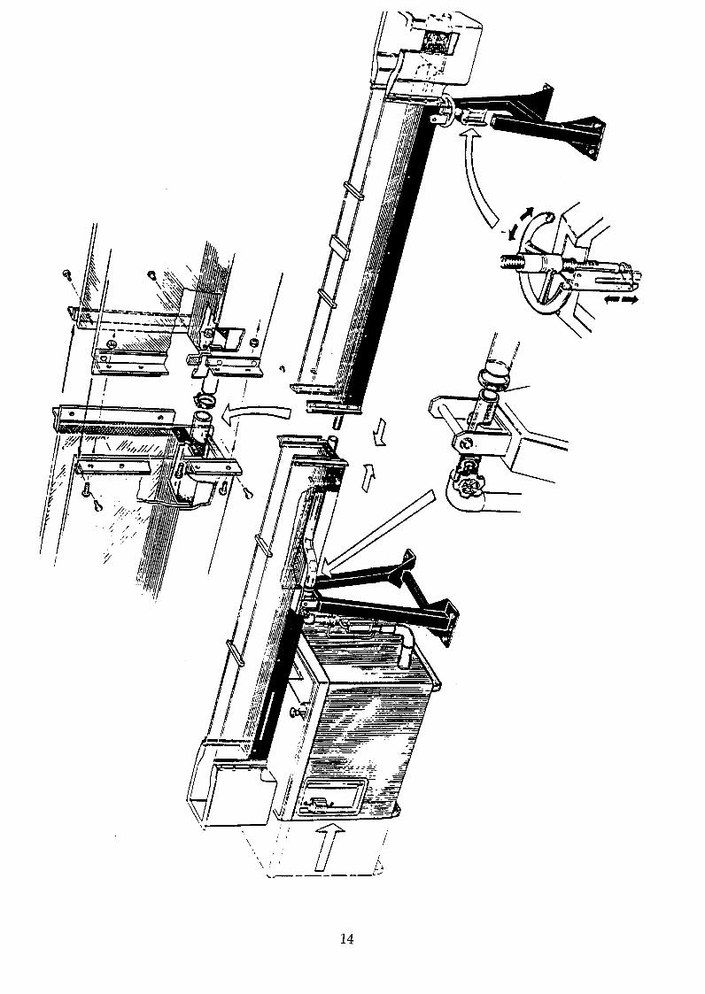
ASSEMBLY
Refer to diagram on page 14.
Note:
Two versions of the Multi Purpose Teaching Flume are available as follows:
C4-2.5m with a 2.5 metre long working section C4-5.0m with a 5.0 metre long working section
The channel for the 2.5 metre version is supplied in one complete section with the inlet and discharge tanks fitted to it and the flexible pipework installed.
The channel for the 5.0 metre version is supplied in two sections, one with the inlet tank and flexible pipework fitted and the second with the discharge tank fitted. It will be necessary to fix the two sections together before mounting the channel on the support pedestals as described below.
The floor should be firm and level (preferably concrete). The apparatus is stable and does not need to be bolted to the floor. However, for added safety, the flume should be secured to the floor using the set of 8 masonry bolts provided, where possible.
For safety during assembly, a pair of trestles approximately 1 metre high will be required to support the channel section while the support pedestals are attached.
1. Carefully unpack the flume section(s), service module, jacking pedestal, bearing pedestal and other associated parts. The parts should be laid out on the floor then inspected for damage and checked against the advice note for any missing parts. Note that the channel section(s) is fragile until assembled.
2. Locate the parts at the proposed site - it would be difficult to move the flume once assembled.
11
3. If installing the 5.0 metre long version the two sections must be fixed together before attempting to lift the channel into place. Position the two sections of channel in line, on the floor, with the mating flanges together. Lightly smear the faces of the mating flanges with the sealing
compound (Seelastik) supplied, then fix the flanges together using the 6 nuts and bolts supplied. Ensure that the two flanges are aligned correctly then tighten the nuts and bolts evenly. It is very important that the inside surfaces of the two channel beds and clear acrylic side walls are straight and level to prevent disturbances to the water flowing along the channel. It is also important that the tops of the clear acrylic sides are flush to ensure smooth travel of the instrument carrier. When the joint is tight carefully remove any excess sealant from the inside of the channel to provide a smooth transition between the sections.
4. Place the spacers provided at equidistant points along the top of the clear acrylic sides. Two spacers are supplied with the 25m version, four spacers are supplied with the 5.0m version.
5. Carefully lift the channel section onto the temporary trestles in the required position.
6. Position the bearing pedestal (incorporating the flowmeter) adjacent to the locating holes in the channel support towards the downstream end (outlet) of the channel section. Apply a smear of grease to the pivot then lift the channel into position on the pedestal and bolt the channel to the pedestal. Ensure that the flume can pivot freely at this end.
7. Position the jacking pedestal (incorporating the jacking hand wheel) adjacent to the locating holes in the channel support at the upstream (inlet) end of the channel section. Adjust the height of the actuator to suit and apply a smear of grease to the pivot, then lift the channel into position on the pedestal and bolt the channel to the pedestal. The temporary trestles can now be removed.
8. Install the flat PVC baffle in the vertical slots at the closed end of the moulded channel on the top of the service module. The slots are polarised to ensure that the baffle is inserted correctly Locate the stilling baffle inside the volumetric tank of the service module. The baffle should be positioned adjacent to the end of the moulded channel on the top of the service module.
12

9. Position the service module at the downstream end of the channel with the aperture in the end of the service module facing the bearing pedestal. Attach the 75mm flexible tube to the stub pipe on the underside of the discharge end tank of the channel and secure the tube using the jubilee clip provided. Adjust the position of the service module so that this flexible tube is located between the baffle and the closed end of the moulded channel. Apply the brakes when the position of the service module is finalised.
10. If practicable the two pedestals should be bolted to the floor using the 8 masonry bolts supplied (4 bolts on each pedestal). When bolted to the floor it is unlikely that the flume will fall over even if accidentally subjected to a severe side impact.
11. Connect the flexible tube from the submersible pump in the service module to the inlet connection at the base of the flowmeter and secure the tube using the jubilee clip provided.
12. Connect the flexible tube running along the underside of the channel (connected to the inlet tank) to the connection downstream of the flow control valve on the bearing pedestal and secure the tube using the jubilee clip provided.
13. Place the perforated plate in the bottom of the channel inlet tank. Wash the glass marbles supplied in warm water, to which a small amount of wetting agent has been added, then place the marbles on top of the perforated plate. The action of the marbles is to reduce the turbulence of the water entering the inlet tank and produce a smooth flow of water into the working section of the channel.
14. Loosely attach the slope indicator pointer and scale to the jacking pedestal. Place a spirit level on the bed of the channel and adjust the jack to level the channel. Adjust the position of the scale to read zero against the pointer. Tighten the fixings on the scale. Note: The scale
will provide an approximate indication of the bed slope. A more precise technique can be used during commissioning.
15. Place the various accessories in a safe place where they will not be damaged.
The flume is ready for commissioning.
13
\ I
/
14

CONNECTION TO SERVICES
ELECTRICAL SUPPLY FOR VERSION C4-2.5-A and C4-5.0-A:
The equipment requires connection to a single phase, fused electrical supply. The standard electrical supply for this equipment is 220/240V, 50Hz. Check that the voltage and frequency of the electrical supply agree with the label attached to the supply cable on the equipment. Connection should be made to the supply cable as follows:-
GREEN /YELLOW BROWN BLUE Fuse Rating
EARTH LIVE (HOT) NEUTRAL 10 AMP
ELECTRICAL SUPPLY FOR VERSION C4-2.5-B and C4-5.0-B:
The equipment requires connection to a single phase, fused electrical supply. The standard electrical supply for this equipment is 120V, 60Hz. Check that the voltage and frequency of the electrical supply agree with the label attached to the supply cable on the equipment. Connection should be made to the supply cable as follows:-
GREEN /YELLOW BROWN BLUE Fuse Rating
EARTH LIVE (HOT) NEUTRAL 20 AMP
ELECTRICAL SUPPLY FOR VERSION C4-2.5-G and C4-5.0-G:
The equipment requires connection to a single phase, fused electrical supply. The standard electrical supply for this equipment is 220/240V, 60Hz. Check that the voltage and frequency of the electrical supply agree with the label attached to the supply cable on the equipment. Connection should be made to the supply cable as follows:-
GREEN /YELLOW BROWN BLUE Fuse Rating
EARTH LIVE (HOT) NEUTRAL 10 AMP
Note: Different motors and impellers are fitted to the water pump to suit the frequency of the supply. Any discrepancy between the frequency of the supply and the equipment should be reported to Armfield Ltd.
15

Cold Water
The equipment is self-contained and does not require permanent connection to a water supply. An initial supply of cold water will be required to fill the
sump tank of the service module. Water will also be required for topping up and cleaning/ flushing after use.
Drain (Cold Water)
The equipment is self-contained and does not require a drain for normal operation. A drain will be required for cleaning/ flushing purposes.
16
COMMISSIONING
1. Check that all packaging has been removed from the service module and channel and all flexible tubes and nuts/bolts are securely tightened.
2. Check that the drain valve on the underside of the service module is closed. Check that the cock below each tapping in the bed of the channel is closed. Check that the gland securing each model mounting hook is tightened. (When not in use the hooks are up-ended and the non-hook end is pushed from under the channel through the gland until the tip is flush with the bed so as not to impede the water flow.)
3. Place a filling hose in the volumetric tank of the service module. Fill the sump tank with clean cold water by lifting the dump valve in the base of the volumetric measuring tank and allowing the water to drain from the volumetric tank into the sump tank. (When lifted, a twist of 900 at the actuator will retain the dump valve in the open position.)
When full ensure that the water level in the sump tank is just below the outlet in the bottom of the volumetric tank.
4. A few drops of wetting agent should be added to the water in the sump tank to minimise the effects of surface tension.
Note: If too much wetting agent is added foaming will occur and it
will be necessary to replace the water.
A few drops of wetting agent may be introduced to the sight tube, on the side of the service module, via the overflow tube at the top. This will reduce the meniscus, making readings clearer.
5. Ensure that the collecting trough/stilling baffle is correctly positioned in the volumetric tank such that the top edge is alongside the exit of the open channel in the moulded top.
6. Close the flow control valve above the flowmeter then connect the mains lead from the service module to the electrical supply.
7. Switch on the RCD on the side of the service module, then press the TEST button to check that the RCD is operating correctly. The RCD must trip. If the RCD does not trip or it trips before pressing the test button then it must be checked by a competent electrician before the equipment is used. Switch on the RCD again.
17

8. Operate the pump ON/OFF switch and confirm that the pump functions. Slowly open the flow control valve and check that water is delivered to the inlet end of the channel.
Allow the water to flow along the channel and discharge into the volumetric tank of the service module. Allow circulation to occur for several minutes to remove air from the system.
9. Release the actuator of the dump valve to close the valve in the bottom of the volumetric tank. Fill the volumetric tank until water runs into the sump tank through the overflow. Now check that the sight tube is full and no air bubbles are present. Repeat this filling several times, ensuring that the sight tube is free from air bubbles.
10. Close the flow control valve and allow water to drain from the volumetric tank until the surface is level with the step in the bottom of the tank. A few drops of wetting agent smeared onto the step will enable an accurate level to be achieved.
Slacken the securing screws at the top and bottom of the sight tube scale and position the scale so that the meniscus of the fluid in the tube is level with the black datum line engraved between the large and small scales. This will ensure that the scale is positioned accurately for volumetric measurements using either of the ranges.
Note: All volumetric readings should be taken with the stilling baffle installed, since calibration has been effected in this condition.
11. Place the stop logs in the slot at the discharge end of the channel to allow the channel to fill with water to the maximum level.
Ensure that the flow control valve is closed, switch on the pump then slowly open the flow control valve and allow the channel to fill with water. When the channel is full, close the flow control valve and switch off the pump. It is suggested that the channel is left standing in this condition for at least one hour to allow any leaks to become visible. Check the channel and pipework for leaks and tighten the appropriate fittings as necessary.
12. The accuracy of the zero setting on the slope indicator can be checked as follows: Attach a hook and point gauge to a carrier and install a
point in the end of the rod. Locate the carrier on the top of the channel sides and position it at one end of the channel. Adjust the gauge to indicate the height of the water then transfer the gauge to the opposite end of the channel. The water level will be the same if the channel is
level. Adjust the handwheel on the jack, if necessary, to obtain the same reading at both ends of the channel. The position of the scale can then be adjusted to read zero against the pointer.
18

13. Remove the stop logs one at a time and allow the channel to drain. Ensure that the flow control valve is closed and the pump is switched off.
Note: After use always allow the water to drain down into the sump tank of the service module. The flow control valve can be opened to allow water to drain from the pipework to the sump via the pump.
The flume is ready for operation using the various accessories.
19

ROUTINE MAINTENANCE
To preserve the life and efficiency of the equipment it is important that the equipment is properly maintained. Regular servicing/maintenance of the equipment is the responsibility of the end user and must be performed by qualified personnel who understand the operation of the equipment.
REGULAR CHECKS
It is important to perform certain checks/maintenance operations at short intervals (typically one month) to prevent deterioration of the equipment. The regular checks must include the following:-
CHECK THE CONDITION OF THE WATER
Check if the water in the sump tank is clean and suitable for use. The water should be changed regularly to avoid stagnation (refer to the notes on the COSHH REGULATIONS at the front of this instruction manual). The use of a
corrosion inhibitor which includes a biocide/disinfectant will reduce the formation of algae or micro-organisms and allow water changes to be performed less frequently. The frequency of water changes will depend on usage, local conditions and whether or not a biocide is used. As most corrosion inhibitors for the treatment of water are used in closed systems, ensure that the inhibitor/biocide used is safe to handle and does not create a
hazard to the health of operators handling models immersed in the treated water.
If it is necessary to change the water, drain all water from the channel then open the drain cock on the underside of the service module and allow the water to drain. A flexible tube connected to the cock will allow the water to be directed to a suitable drain.
Refill the sump tank as described in the commISSIOning section of this instruction manual, using clean water and add the correct amount of an appropriate corrosion inhibitor with biocide (must be suitable for use with aluminium alloy). The sump tank contains approximately 250 litres of water. Refer to the details supplied with the inhibitor used for information on dilution.
Switch on the pump with the flow control valve closed, then gradually open the valve to circulate the water through the channel! service module to ensure that the inhibitor has dispersed thoroughly and coated all wetted surfaces with a protective film.
20

CHECK FOR LEAKS
The channel, service module and interconnecting pipework should be checked visually for drips or staining associated with leaks. Any leaks identified should be attended to immediately to minimise deterioration of the equipment. Refer to the notes on RESEALING below for further information.
CHECK THE CONDITION OF THE CHANNEL BED
The surface of the aluminium bed inside the channel section is treated with chlorinated rubber paint (Oxford Blue BSI05) to provide corrosion resistance. It is important that this finish is maintained in perfect condition to prevent corrosion of the bed. Inspect the bed thoroughly for any sign of damage to, or deterioration of, the paint finish, such as scratches, discoloration, peeling, blistering etc. Care should be taken to look for small indentations through the paint surface caused by instruments such as the point of a hook and point gauge. Small areas of damage can be touched up locally provided that care is taken to remove all traces of corrosion before repainting. The frequency of repainting will depend on usage but repainting of the whole bed must be undertaken if any deterioration is located, however small. If repainting is necessary refer to the notes on REPAINTING below for further information.
FULL ANNUAL SERVICE
It is important to carry out a full service at regular intervals, at least annually or more frequently according to usage and local conditions. The full service must include the following:-
Note: As the channel will be out of use for several days while drained, cleaned, repainted etc. it is sensible to program the full service to coincide with an end of term shutdown etc.
CHECK FOR LEAKS
Install the full set of stop logs at the discharge end of the channel. Operate the pump then open the flow control valve to fill the channel with water. Close the flow control valve then switch off the pump and allow the channel to stand for at least 24 hours. Check all joints, pipework etc. for leaks and mark any leaks for subsequent action.
21
DRAINING/CLEANING
Having inspected for any leakage all water should be drained from the channel and sump tank.
The channel and service module should be cleaned using warm water with household detergent then rinsed and dried. Particular attention should be paid to the clear acrylic walls of the channel if deposits are obscuring the view, taking care not to scratch the soft plastic. In order to restore visual clarity to scuffed, disco loured or surface crazed acrylic, an abrasive metal polish may be used.
After cleaning with warm soapy water, the painted bed should be checked for damage as described above. If repainting is necessary proceed as follows:
While the service module is drained the submersible pump can be checked. Refer to the leaflet supplied by the pump manufacturer for service details.
REPAINTING OF THE CHANNEL BED
If repainting is necessary the following steps should be carried out:
All existing paint on the bed should be completely removed and the surface degreased prior to painting.
The surface of the bed and the joints between the clear acrylic side walls and the bed must be fully dry prior to painting. A hair drier can be used to speed up this operation but care should be taken not to heat the plastic excessively. Within 4 hours of cleaning, the bed should be painted with one coat of an appropriate etch primer/undercoat. When the primer is dry, the bed should be painted with two top coats of chlorinated rubber paint, paying particular attention to the joints in the bed and internal comers.
The primer used should be a two pack etch primer/undercoat suitable for direct application to aluminium alloy and overpainted with chlorinated rubber paint. The dry film thickness of the primer should be 20 microns minimum.
The two top coats should be applied using chlorinated rubber paint. The dry film thickness of the top coats should be 80 microns minimum. The colour specification of the original paint is Oxford Blue, BSIOS.
The bed should be left for a minimum period of two days before refilling with water.
22

CHECK THE CONDITION OF THE EXTERNAL P AINTWORK
Having checked/repainted the bed, any damage to external paintwork should be identified and touched up.
Any corrosion should be removed and the surface degreased.
The cleaned surface should be primed before painting. The two pack etch primer / undercoat used inside the flume can be used for the surfaces of the bed external to the working section. A two pack etch primer/undercoat suitable for use with mild steel should be used to coat the mild steel support pedestals.
The chlorinated rubber paint used for repainting the channel bed may be used for this application but a better finish will be obtained using polyurethane enamel paint.
The colour specification of the original paint is Oxford Blue, BSI05
RESEALING
Any leaks, which were identified while the channel and pipework were filled, should be resealed using an appropriate sealant. There are two types of sealant used in the construction of the channel, 'Silicone sealant' and 'Mastic sealant'.
Silicone sealant is supplied in a tube and is best used for internal glass joints to provide a smooth finish. The sealant cures at room temperature but remains flexible.
Mastic is supplied in strip form and is used for tank-to-bed and bed-to-bed joints. Glass joints have mastic between the glass and the support strip. The mastic is non-hardening.
Dripping leaks generally originate from the clear acrylic side butt joints adjacent to the flume bed. They may be made good by applying silicone sealant into the corner formed by the walls and the bed. Although leakage may not be evident, check the seal between the clear acrylic panels and the bed of the channel. Apply silicone sealant to the comer of the joint if any doubt exists.
All PVC and rubber hoses/ sleeves must be checked and replaced if perished.
Despite appearing leak-tight, all joints should be checked for integrity and reseated if necessary.
Leaks from threaded joints should be sealed by wrapping PTFE tape around the thread before refitting.
23

LUBRICA nON
All moving parts should be lubricated using a general purpose grease. Special attention should be paid to the pivot, the jacking arrangement and the trunnions attaching the flume to the support pedestals.
Where usage is unusually heavy or local conditions are extreme increase the frequency of lubrication to every 6 months.
REFILLING
Refill the service unit as described in the monthly checks (check the condition of the water).
Refer to the assembly and commissioning sections of this instruction manual for details on how to check that the channel section is straight and level.
CLEANING MODELS
Models used in the channel should be checked for damage and repaired if necessary. All models should be washed in warm water to which household detergent has been added.
Many of the models use clear acrylic or rigid PVC in the construction and should not be cleaned using strong solvents such as acetone, trichloroethylene or tetrachloride which will soften the material and cause crazing of the clear acrylic.
In order to restore visual clarity to scuffed, disco loured or surface crazed acrylic, an abrasive metal polish may be used.
24

MODELS AVAILABLE FOR USE IN THE C4 FLUME
The following accessories are supplied as standard with the C4-2.5m and C4- 5.0m flumes:
Sharp crested weir
Broad crested weir
Adjustable undershot weir (sluice gate)
Crump weir
Venturi flume (2 sections to line the vertical walls of the channel)
Two hook and point gauges, 300mm range with Vernier scale
The following accessories are supplied as standard with the service module:
90 degree Vee notch
Rectangular notch
Hook and point gauge, 150mm range with Vernier scale
Measuring cylinder (to measure very low volumetric flowrate)
The following accessories are available as an option for use with the C4-2.5m and C4-5.0m flumes:
C4-61
C4-62
C4-63
C4-64
C4-65
C4-66
C4-67
Pitot tube and manometer board
Culvert fitting, incorporates one square edge, one rounded edge
Flow splitters, central wall with various nosepieces
Free overflow spillway section, complete with ski jump, sloping apron and blended reverse curvature attachments
Siphon spillway and air regulated siphon
Model radial gate
Wave generator and wave absorbing beach. Requires an electrical supply and therefore available in three versions:
C4-67-A 220/240 Volts, 1 Phase, 50 Hz
C4-67-B 120 Volts, 1 Phase, 60 Hz
220/240 Volts, 1 Phase, 60 Hz C4-67-G
25

C4-68
C4-69
False floor sections for gradually varied profiles, comprising: variable height laminated ramp, 2 parallel face sections with 2
end ramps and support piece to create raised false floor using 1
parallel face section
Artificially roughened bed 25m long section (2 required for C4- 5.0m)
26

GENERAL ASSEMBLY INSTRUCTIONS FOR MODELS
The models which sit on the channel bed (with the exception of the Venturi flume, the false floor sections and the artificially roughened bed) are held in place by a clamping hook assembly. These are pushed through the channel bed from the top and are held in place by a gland located beneath the channel bed. Normally the hooks are up-ended and the non-hook end is pushed from under the channel through the gland until the tip is flush with the bed so as not to impede the water flow. There are two hooks per 2.5 metre length of channel section. The bed-mounted models are hooked in place via a retaining bar on the underside of the model. The appropriate hook is pushed upwards to clear the channel bed. The required model is placed over the hook and then slid along until its retaining bar is beneath the hook. The hook is then pulled from beneath and clamped by tightening the gland. The model will be held in place until the gland is released and the hook raised.
The Venturi flume is held in place by a simple stretcher screw. This is placed between the two sections of the Venturi and adjusted to clamp them against the side walls of the channel.
b1 b2 )I b3
NOTE: The stretcher must be placed above the level of the water so as not to interfere with the flow.
27
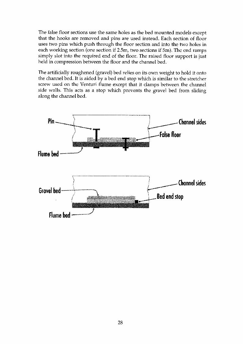
The false floor sections use the same holes as the bed mounted models except that the hooks are removed and pins are used instead. Each section of floor uses two pins which push through the floor section and into the two holes in each working section (one section if 25m, two sections if Sm). The end ramps simply slot into the required end of the floor. The raised floor support is just held in compression between the floor and the channel bed.
The artificially roughened (gravel) bed relies on its own weight to hold it onto the channel bed. It is aided by a bed end stop which is similar to the stretcher screw used on the Venturi flume except that it clamps between the channel side walls. This acts as a stop which prevents the gravel bed from sliding along the channel bed.
\
Pin--+-. .
11.1.. ..______ ... Channel sides
.t.---- \ falseftoor
Aumebed
\ \. l
I J-------Chonnel sides
'I Bed end slop
Flume lied
Grovel bed
28

Use of Stop Logs
Stop logs are simple oblong shapes which slot one after the other into the discharge end of the channel. Their main use is to raise the water level to different heights. A further use includes a simple overshot weir of varying height.
Plasticine is also supplied with the flumes. This is used on the leading edge of the model and is placed between the side wall of the channel and the side of the model. This is to ensure that water flows over the model and not around it.
Channel side waUs
(Flume bed Plasticine between model and base
29

INDEX TO EXPERIMENTS
Experiment Page No.
DATA SHEET 1
General Nomenclature 1
DATA SHEET 2
Nomenclature for Free Surface Flow 11
DATA SHEET 3
Operating the C4-61 Pitot Tube And Manometer Board 111
DATA SHEET 4
Operating the C4-67 Wave Generator And Wave Absorbing Beach V11
EXPERIMENT A
Characteristics of flow over a Sharp Crested Overshot Weir. A-I EXPERIMENT B
Characteristics of flow over a Broad Crested Weir. B-1
EXPERIMENT C
Characteristics of flow over a Crump Weir. EXPERIMENT D
C-l
Discharge beneath a Sluice Gate
EXPERIMENT E D-l
The force on a Sluice Gate.
EXPERIMENT F E-l
The critical depth - Derivation of the Specific Energy Equation. F-l EXPERIMENT G
The Hydraulic Jump G-l EXPERIMENT H
Characteristics of flow through a Venturi Flume H-l EXPERIMENT J
Characteristics of flow through a Culvert J-l
30

EXPERIMENT K
Characteristics of flow around Flow Splitters
EXPERIMENT L
K-1
Characteristics of flow over a Dam Spillway EXPERIMENT M
L-1
Characteristics of flow through a Syphon Spillway
EXPERIMENT N M-1
Characteristics of flow through an Air Regulated Syphon
EXPERIMENT P N-1
Characteristics of flow under a Radial Gate
EXPERIMENT Q P-1
Characteristics of flow over False Floor Sections
EXPERIMENT R Q-1
Characteristics of flow over a Gravel Bed R-1
31

C4 - MULTI-PURPOSE TEACHING FLUME
DATA SHEET 1
General Nomenclature
The symbols used in describing the experiments have been listed below for convenience. Any additional symbols required are defined in the text where they occur.
General:
b Breadth of channel/weir etc (m)
Gravitational constant (9.81m S"2)
Difference in manometer readings (m)
Volumetric flowrate (m3 S"l)
Hydraulic mean radius (m)
Temperature of water (Oe)
Local fluid velocity (ms-1)
Mean fluid velocity (m S"l)
Depth of fluid at any location (m)
Density of fluid (kg m-3)
g
h
Q
R
T
u
V
y
p
NOTE: For free surface flow experiments it has been assumed that the velocity distribution is uniform across the section and each fluid layer moves at velocity u; thus the velocity head indicated by a
Pitot tube for one layer of the fluid is assumed to be the same for every other layer and so represents the kinetic energy per unit weight of fluid.
e -e
lAH e e
(
Invert
Do'um
1
C4 - MULTI-PURPOSE TEACHING FLUME
DATA SHEET 2
Nomenclature for Free Surface Flow
c Velocity of gravity wave ill still shallow water (sometimes called celerity)
Cc Coefficient of contraction
Cd Coefficient of discharge
Cy Coefficient of velocity (0.95<Cy <1.0)
E Specific energy head (total energy head measured relative to channel bed) E = Y + V2/2g
Note: If the datum is the channel bed then E = H (z = 0)
F Force of a stream, F = pgby2/ 2 + pQ2/by
h Height of water surface above a weir crest
H Total energy head or total head (height of energy line (e) above a datum) H = Y + V2/2g + z
LlH Loss of total head between specified sections
p
P
Pressure at height y above channel bed
Height of weir crest above channel bed
Yx Height of water surface above the bed at position x
Yc Critical depth
yg Height of sluice gate opening
z Position of bed relative to datum
S Slope of energy line (for uniform flow assumed to be the same slope as the channel bed and the surface of the water) = Sin e
NOTE: Where values for E and H cannot conveniently be measured then they should be computed using the expressions given above.
11

C4 - MULTI-PURPOSE TEACHING FLUME
DATA SHEET 3
OPERATING THE C4-61 PITOT TUBE AND MANOMETER BOARD
The Pitot tube and manometer board is an optional accessory (Armfield order code C4-61) and is used in conjunction with the C4 Multi Purpose Teaching Flume to measure the local velocity of water flowing through the working section.
EQUIPMENT SET-UP
Flow
PRIMING THE PITOT TUBE AND MANOMETER
Partially fill the flume with water so that the head of the Pitot tube can be immersed when installed on the flume. The water in the flume should not be flowing during the priming procedure.
Before installing the Pitot tube and manometer on the flume it is necessary to prime them with water. Fill the manometer reservoir with water, ensuring that the valve at the base of the reservoir is closed. Position the manometer above the Pitot tube with the Pitot tube sloping uphill (cranked head at the top). Open the isolating valves at the base of the manometer.
Open the reservoir and allow water to flow through the flexible tubing until it flows through the static and total head holes in the Pitot tube. During this operation the reservoir must not be allowed to empty, thus letting air into the
iii
C4 - MULTI-PURPOSE TEACHING FLUME
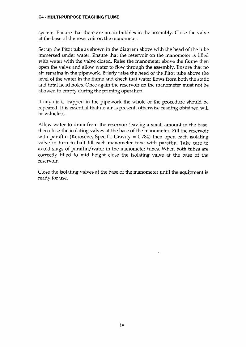
system. Ensure that there are no air bubbles in the assembly. Close the valve at the base of the reservoir on the manometer.
Set up the Pitot tube as shown in the diagram above with the head of the tube immersed under water. Ensure that the reservoir on the manometer is filled with water with the valve closed. Raise the manometer above the flume then open the valve and allow water to flow through the assembly. Ensure that no air remains in the pipework. Briefly raise the head of the Pitot tube above the level of the water in the flume and check that water flows from both the static and total head holes. Once again the reservoir on the manometer must not be allowed to empty during the priming operation.
If any air is trapped in the pipework the whole of the procedure should be repeated. It is essential that no air is present, otherwise reading obtained will be valueless.
Allow water to drain from the reservoir leaving a small amount in the base, then close the isolating valves at the base of the manometer. Fill the reservoir with paraffin (Kerosene, Specific Gravity = 0.784) then open each isolating
valve in turn to half fill each manometer tube with paraffin. Take care to avoid slugs of paraffin/water in the manometer tubes. When both tubes are correctly filled to mid height close the isolating valve at the base of the reservOIr.
Close the isolating valves at the base of the manometer until the equipment is ready for use.
IV
C4 - MULTI-PURPOSE TEACHING FLUME
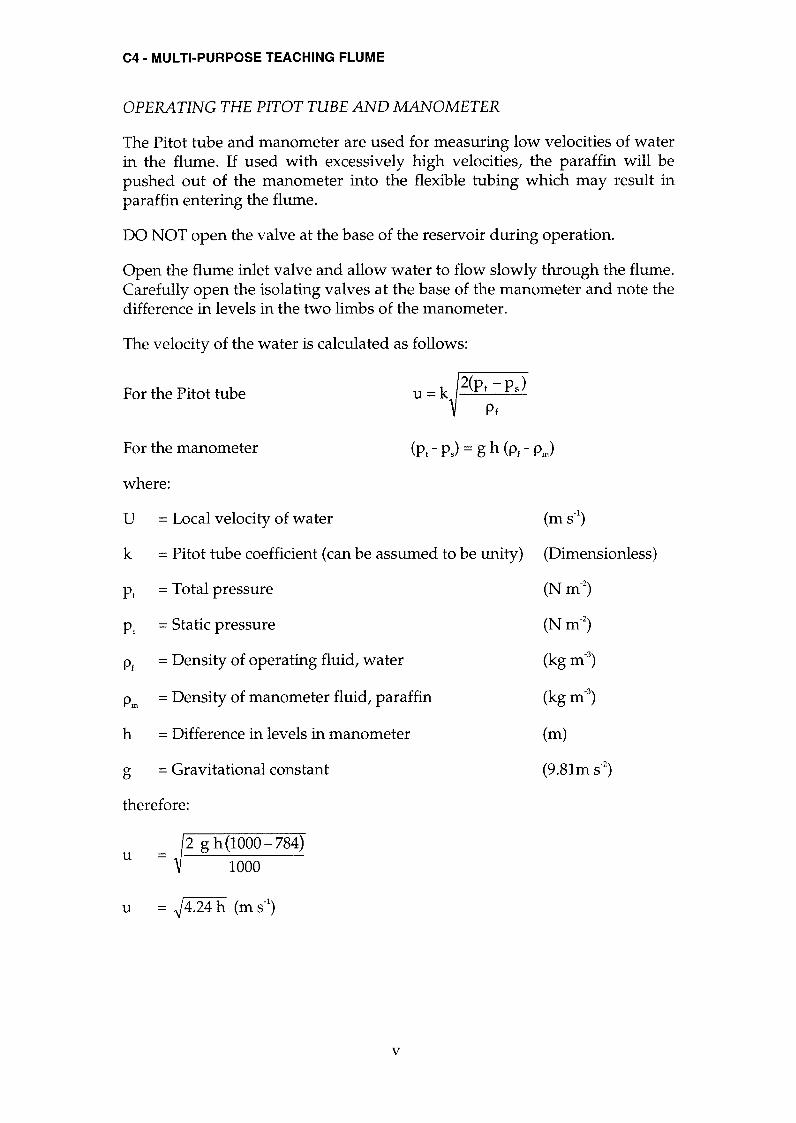
OPERATING THE PITOT TUBE AND MANOMETER
The Pitot tube and manometer are used for measuring low velocities of water in the flume. If used with excessively high velocities, the paraffin will be pushed out of the manometer into the flexible tubing which may result in paraffin entering the flume.
DO NOT open the valve at the base of the reservoir during operation.
Open the flume inlet valve and allow water to flow slowly through the flume. Carefully open the isolating valves at the base of the manometer and note the difference in levels in the two limbs of the manometer.
The velocity of the water is calculated as follows;
For the Pitot tube u = k 2(pt -Ps) Pf
For the manometer (PI - Ps) = g h (PI - Pm)
where:
u = Local velocity of water (m S.l)
k = Pitot tube coefficient (can be assumed to be unity) (Dimensionless)
PI = Total pressure (N m-2)
Ps = Static pressure (N m-2)
PI = Density of operating fluid, water (kg m-3)
Pm = Density of manometer fluid, paraffin (kg m-3)
h = Difference in levels in manometer (m)
g = Gravitational constant (9.81m S.2)
therefore:
u =
u = .J4.24 h (m S.I)
v

C4 - MULTI-PURPOSE TEACHING FLUME
For defining the position of the Pitot tube relative to the flume the following convention is used:
Xp = distance along the flume (scale on side of flume) (m)
(m)
(m)
y p = location across flume
zp = height above bed of flume (vertical level gauge)
These dimensions can be tabulated with the other results obtained.
This assembly can be used with many of the other accessories where velocities are required. The velocity profile in the flume can be obtained by moving the Pitot tube vertically and horizontally across the flume at different sections, noting the readings on the manometer at each position and converting these readings to a series of velocity profiles.
VI
C4 - MULTI-PURPOSE TEACHING FLUME
DATA SHEET 4
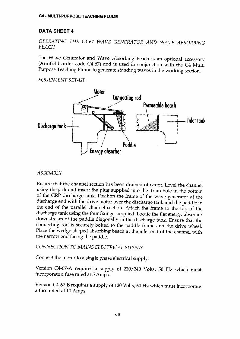
OPERATING THE C4-67 WAVE GENERATOR AND WAVE ABSORBING BEACH
The Wave Generator and Wave Absorbing Beach is an optional accessory (Armfield order code C4-67) and is used in conjunction with the C4 Multi Purpose Teaching Flume to generate standing waves in the working section.
EQUIPMENT SET-UP
Motor ~ Connecting rod
/ Permeable beach
Discharge tonk
Po die Energy absorber
Inlef tank
ASSEMBLY
Ensure that the channel section has been drained of water. Level the channel using the jack and insert the plug supplied into the drain hole in the bottom of the GRP discharge tank. Position the frame of the wave generator at the discharge end with the drive motor over the discharge tank and the paddle in the end of the parallel channel section. Attach the frame to the top of the discharge tank using the four fixings supplied. Locate the flat energy absorber downstream of the paddle diagonally in the discharge tank. Ensure that the connecting rod is securely bolted to the paddle frame and the drive wheel. Place the wedge shaped absorbing beach at the inlet end of the channel with the narrow end facing the paddle.
CONNECTION TO MAINS ELECTRICAL SUPPLY
Connect the motor to a single phase electrical supply.
Version C4-67-A requires a supply of 220/240 Volts, 50 Hz which must incorporate a fuse rated at 5 Amps.
Version C4-67-B requires a supply of 120 Volts, 60 Hz which must incorporate a fuse rated at 10 Amps.
Vll

C4 - MULTI-PURPOSE TEACHING FLUME
Version C4-67-G requires a supply of 220/240 Volts, 60 Hz which must incorporate a fuse rated at 5 Amps.
Ensure that the electrical supply is protected by an RCD for safe operation of the Wave Generator.
Before connecting the electrical supply ensure that the switch on the speed controller is off and the speed control is set to minimum.
OPERATION
Operate the pump then gradually open the flow control valve to admit water to the flume. When the water is at the required level (suggested height between one third and one half of full channel height) close the valve and switch off the pump. Check that the speed controller is set to minimum then switch on the controller. Gradually increase the speed of the motor until waves are produced. Maintain the paddle at this speed and observe and sketch the waveform produced together with the effect of the permeable beach on the waves. The motor speed can be increased in gradual amounts to vary the frequency of the wave formation, but care must be taken not to increase the speed too much or spillage will occur if the height if the water is excessive.
Vlll

C4-20 BASIC SET OF ACCESSORIES
EXPERIMENT A
Characteristics of flow over a Sharp Crested Overshot Weir.
OBJECTIVE
To determine the relationship between upstream head and flowrate for water flowing over a Sharp Crested weir; to calculate the discharge coefficient and to observe the flow patterns obtained.
EQUIPMENT SET-UP
Multi-Purpose Teaching Flume, C4
Sharp Crested weir Hook and point level gauge, 300mm scale Stopwatch if measuring flowrate using the volumetric tank (not supplied)
Air cavity )eralion pipe (open)
/ Nappe
Clinging nappe Aeration pipe (closed)
A-I

C4-20 BASIC SET OF ACCESSORIES
SUÑUÆARYOFTHEORymACKGROUND
For a rectangular sharp crested weir:
2 3
Q = -Cdb.J2gh2 3 therefore:
Q Cd= 3 ~bÆh2
3
where:
Q = Volume flowrate (m3.s-1)
= Volume/time (using volumetric tank)
Cd = Coefficient of discharge
b = Breadth of weir
(Dimensionless)
h = Head above crest of weir (upstream)
(m)
(m)
(9.81ms-2) g = Gravitational constant
P = Height of weir crest above bed (m)
When the rectangular weir extends across the whole width of the channel it is called a suppressed weir and the Rehbock formula can be applied to determine Cd as follows:
h Cd = 0.602 + 0.083.- P
PROCEDURE
Ensure the flume is level, with no stop logs installed at the discharge end of the channel. Measure and record the actual breadth b (m) of the sharp crested overshot weir (rectangular weir).
Install the weir in the flume with the sharp edge upstream. Ensure that the weir is secured using a mounting hook through the bed of the flume. For accurate results the gaps between the weir and the channel should be sealed on the upstream side using Plasticine. Position a hook and point level gauge on the channel sides, above the weir, with the point fitted.
A-2

C4-20 BASIC SET OF ACCESSORIES
The datum for all measurements will be the top edge of the weir plate. Carefully adjust the level gauge to coincide with the top of the weir, taking care not to damage the edge of the weir, then record the datum reading. Alternatively, to avoid damage to the weir, open the flow control valve and admit water into the channel until it discharges over the weir then close the flow control valve to stop the flow of water. When water stops flowing over the weir adjust the level gauge to coincide with the surface of the water and record the datum reading.
Adjust the level gauge to measure the position of the bed relative to the top of the weir and record the height of the weir P (m). Reposition the level gauge some way upstream from the weir.
Adjust the flow of water into the flume to obtain heads h, increasing in about G.GlOm steps. For each step measure the flowrate Q and the head h. The flowrate Q can be determined using the direct reading flowmeter or the volumetric tank with a stopwatch. For accurate results the level gauge must be far enough upstream to be clear of the draw-down adjacent to the weir.
If the nappe tends to cling to the back face of the weir then the ventilation tubes are filled with water. Ventilate the nappe by inserting the end of a piece of hollow tube into the space behind the weir. The nappe should spring away from the weir.
Sketch the flow pattern as the water flows over the weir when the nappe is ventilated properly. Reduce the flowrate slightly then block the ventilation tubes and sketch the flow pattern with the nappe clinging to the weir. Measure the flowrate Q and the head h while the nappe is clinging to the weir.
RESULTS AND CALCULATIONS
Tabulate your measurements and calculations as follows:
Breadth of Weir b =............(m) P =............(m)
Height of weir
h Q h3/2 Logh LogQ Cd
A-3

C4-20 BASIC SET OF ACCESSORIES
Plot Q against h, log Q against log h and Cd against h.
From the straight-line graph of log Q against log h find the intercept log k on the log Q axis and the gradient m.
The relationship between Q and h is then Q = k hID.
Calculate Cd for the condition when the nappe is not properly ventilated.
Calculate the Cd predicted by the Rehbock formula.
CONCLUSIONS
Is Cd constant for this weir? If not, under what conditions does it vary?
What average value of Cd would you use for this weir?
How does the value for Cd predicted by the Rehbock formula compare with your average value?
How do your values for k and m in the equation Q = khn agree with the theoretical equation for a sharp crested rectangular weir?
Does your value for Cd when the nappe is unventilated differ from your average value? If so, why?
Comment on the profile of the nappe when ventilated and unventilated.
A-4

C4-20 BASIC SET OF ACCESSORIES
EXPERIMENT B
Characteristics of flow over a Broad Crested Weir.
OBJECTIVE
To determine the relationship between upstream head and flowrate for water flowing over a Broad Crested weir (long base weir), to calculate the discharge coefficient and to observe the flow patterns obtained.
EQUIPMENT SET-UP
Multi-Purpose Teaching Flume C4
Broad Crested Weir Hook and point gauge, 300mm scale - 2 required Stopwatch if measuring flowrate using the volumetric tank (not supplied)
..- - -. - - - - - - - - - - - - -
Total head line
B-1

C4-20 BASIC SET OF ACCESSORIES
SUMMARYOFTHEORymACKGROUND
Provided that the weir is not submerged (downstream water level is low) the actual flow over a Broad Crested weir is given by:
3
Q = 1.704 Cd b H2 therefore: Q
Cd = 3
1.704 b H2
where:
Q = Volume flowrate ( 3 -1) m.s
= Volume/time (using volumetric tank)
Cd = Coefficient of discharge (Dimensionless)
b = Breadth of weir (m)
(m) H = Total Head upstream of weir
V2 Q2 Q2 = Yo + 2 = Yo +
2 A 2 = Yo +
2 (y b)2 g g g 0
When using this type of weir in a real application it is more convenient to measure the head hu upstream of the weir. The flow equation must be modified to take account of the velocity head component as follows:
3
Q = 1.704 Cd Cy b hu2
Therefore Q
Cy = 3
1.704 Cd b hu 2
where:
Cv = Coefficient of velocity (Dimensionless)
hu = Head above the weir crest (upstream) (m)
= Upstream depth of flow (Yo) - Height of weir (P)
Note: The weir can be used for flow measurement using a single measurement of level upstream provided that a standing wave exists downstream of the weir. The condition at which the standing wave ceases is called the modular limit and is investigated in later experiments.
B-2

C4-20 BASIC SET OF ACCESSORIES
PROCEDURE
Ensure the flume is level, with no stop logs installed at the discharge end of the channel. Measure and record the actual breadth b (m) of the broad crested weIr.
Install the weir in the flume with the rounded comer upstream. Ensure that the weir is secured using a mounting hook through the bed of the flume. For accurate results the gaps between the weir and the channel should be sealed on the upstream side using Plasticine. Position two hook and point level gauges on the channel sides, adjacent to the weir, each with the point fitted.
The datum for all measurements will be the crest of the weir. Carefully adjust the level gauges to coincide with the top of the weir and record the datum readings. Using one level gauge carefully measure the height of the weir above the bed hw(m) taking care not to damage the surface of the weir. Position this level gauge above the weir near to the discharge end. Position the second level gauge some way upstream from the weir.
Adjust the flow of water into the flume to obtain heads y ()I increasing in about O.010m steps. For each step measure the flowrate Qactual' the upstream depth of flow above the weir Yo and the depth of flow over the weir Yl (where the flow becomes parallel to the weir). The flowrate Qactual can be determined using the direct reading flowmeter or the volumetric tank with a stopwatch. For accurate results the level gauge must be far enough upstream to be clear of the draw-down over the weir.
At each setting also observe and sketch the flow patterns over the weir.
Gradually increase the total depth of the water downstream of the weir by adding stop logs at the discharge end of the channel. For each step measure the flowrate Qactual' the upstream depth of flow Yo and the depth of flow over the weir Yl' Observe and sketch the flow patterns over the weir.
RESULTS AND CALCULATIONS
Tabulate your readings and calculations as follows: Breadth of Weir b =............(m) Height of weir hw =............(m)
Yo Yl Qactual Ho Qtheoretica1 Cd
Plot graphs of Qactual against Ho and Cd against Ho'
B-3

C4-20 BASIC SET OF ACCESSORIES
CONCLUSIONS
Does the magnitude of the flowrate affect the discharge coefficient Cd? Does Cd increase or decrease with increasing flowrate?
Does the height of the weir affect the discharge coefficient?
What is the pattern of the water as it passes over the weir?
Would you expect the length of the weir crest to affect the discharge coefficient Cd?
What is the effect of drowning the weir (increasing the downstream depth)?
B-4

C4-20 BASIC SET OF ACCESSORIES
EXPERIMENT C
Characteristics of flow over a Crump Weir.
OBJECTIVE
To determine the relationship between upstream head and flowrate for water flowing over a Crump weir; to determine the modular limit and to observe the flow patterns obtained.
EQUIPMENT SET-UP
Multi-Purpose Teaching Flume, C4
Crump weir Hook and point gauge, 300mm scale - 2 required Stopwatch if measuring flowrate using the volumetric tank (not supplied)
Note: If available, the Pitot tube and manometer, C4-61 (optional accessory)
can be used to measure velocity of the water directly.
V 2 o
129 ~L~~~~=~
V12
~_i~~_~
MODULAR FLOW
NON-MODULAR FLOW
C-l
C4-20 BASIC SET OF ACCESSORIES
SUMMARYOFTHEORymACKGROUND
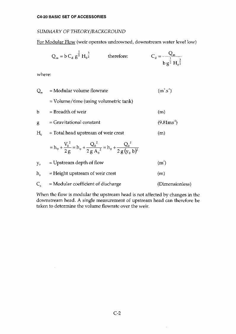
For Modular Flow (weir operates undrowned, downstream water level low)
.! 3
Qm = b Cd g2 Hol therefore: Cd= 9m 3
b g2 HOl
where:
Qrn = Modular volume flowrate (m3.s.1)
= Volume/time (using volumetric tank)
b = Breadth of weir
g = Gravitational constant
(m)
(9.81ms.2)
Ho = Total head upstream of weir crest (m)
v2 Q2 Q2 = ho + ~ = ho + 0
2 = ho + (yO )2 2g 2g Ao 2g 0
b
Yo = Upstream depth of flow (m2)
ho = Height upstream of weir crest (m)
Cd = Modular coefficient of discharge (Dimensionless)
When the flow is modular the upstream head is not affected by changes in the downstream head. A single measurement of upstream head can therefore be taken to determine the volume flowrate over the weir.
C-2

C4-20 BASIC SET OF ACCESSORIES
For Non-Modular Flow (weir crest drowned, downstream water level high)
The weir ceases to act in modular fashion when:
HI ~ 0.70 Ho
where:
HI = Total head downstream of weir crest (m)
_
V/ _
Q/ _
Q/ - hI + -
- hI + - hI + (y ) 2 g 2 g A/ 2 g 1
b 2
Ho = Total head upstream of weir crest (m)
_
Va 2
_
Qo 2
_
Qo 2
-ho +--ho + -ho + (y ) 2 g 2 g A/ 2 gob
2
When the flow is not modular the upstream head is affected by changes in the downstream head. A single measurement of upstream head is no longer adequate to determine the actual flowrate Q since Q ~ Qm .
A reduction factor can be used to correct for non-modular flow where:
f Q =
Qm (Dimensionless)
PROCEDURE
Ensure the flume is level, with no stop logs installed at the discharge end of the channel. Measure and record the actual breadth b (m) of the Crump weir.
Install the weir in the flume towards the inlet end of the channel with the short face of the weir facing the inlet tank. Ensure that the weir is secured using a mounting hook through the bed of the flume. For accurate results the gaps between the weir and the channel should be sealed on the upstream side using Plasticine.
Position two hook and point level gauges on the channel sides, adjacent to the weir, each with the point fitted.
The datum for all measurements will be the bed of the channel. Carefully adjust each level gauge in turn to coincide with the bed of the channel and record the datum readings.
Position one level gauge some way upstream from the weir. Position the second level gauge some way downstream from the weir.
C-3

C4-20 BASIC SET OF ACCESSORIES
Open the flow control valve and allow the water to flow into the flume then adjust the valve to maintain a depth Yo of 0.060m upstream of the weir. Maintain this level whilst measuring the downstream depth of flow Yl and the flowrate Q. For accurate results the upstream level gauge must be far enough upstream to be clear of the draw-down over the weir. Similarly the downstream level gauge must be in clear water after the level has stabilised.
Repeat this for O.OlOm increments of Yot recording the measurements of Yot Yl and Q and noting any variation in the flow patterns over the weir.
Add stop logs one at a time at the discharge end of the flume. When the levels have stabilised record the measurements of Yot Yl and Q. Observe the changes in the flow patterns over the weir.
RESULTS AND CALCULATIONS
Tabulate your readings and calculations as follows:
Breadth of Weir b =............(m)
Yo y, Q Ho H, Qm C~ f
Determine the average coefficient of discharge for modular flow conditions.
Plot values of f against HI then determine the modular limit - the value of Ho
HI where f ceases to be unity. Ho
CONCLUSIONS
How does your value for the modular limit compare with the recognised value of approximately 0.7?
How does the value of f change when the weir is drowned?
How are the flow patterns affected when flow over the weir changes from modular to non-modular flow?
C-4
C4-20 BASIC SET OF ACCESSORIES
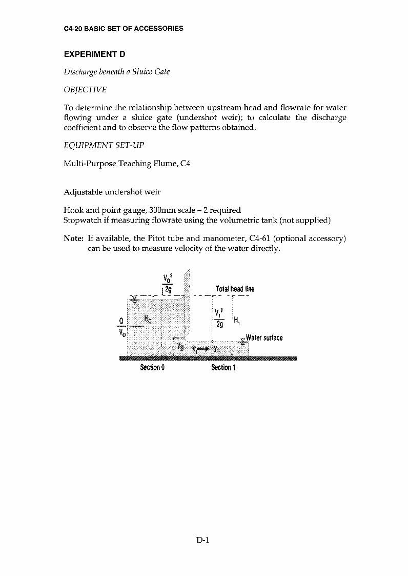
EXPERIMENT D
Discharge beneath a Sluice Gate
OBJECTIVE
To determine the relationship between upstream head and flowrate for water flowing under a sluice gate (undershot weir); to calculate the discharge coefficient and to observe the flow patterns obtained.
EQUIPMENT SET-UP
Multi-Purpose Teaching Flume, C4
Adjustable undershot weir
Hook and point gauge, 300mm scale - 2 required Stopwatch if measuring flowrate using the volumetric tank (not supplied)
Note: If available, the Pitot tube and manometer, C4-61 (optional accessory) can be used to measure velocity of the water directly.
VOZ
__._ [2F_ Total head line
H1
Section 0 Sectíon 1
D-l

C4-20 BASIC SET OF ACCESSORIES
SUMMARY OF THEORymACKGROUND
For flow beneath a sharp edged undershot weir it can be shown that;
Q = Cd b Y g .J2 g Yo therefore: Q
Cd= b Yg .J2g Yo
where:
Q = Volume flowrate (m3.s-1)
= Volume/time (using volumetric tank)
Cd = Discharge coefficient (Dimensionless)
b = Breadth of weir
g = Gravitational constant
(m)
(m)
(m)
(9.81m S-2)
Yg = Height of weir opening above bed
Yo = Upstream depth of flow
V 2 Q2 Ho = Yo -t- = Yo 2 (y b )2 g g 0
V2 Q2 HI = Y 1 -t- = Y 1 2 (y b)2 g g 1
where:
Ho = Total head upstream of weir (m)
HI = Total head downstream of weir (m)
Yl = Downstream depth of flow (m)
Vo = Mean velocity upstream of weir (m S-I)
Vj = Mean velocity downstream of weir (m S-I)
D-2

C4-20 BASIC SET OF ACCESSORIES
PROCEDURE
Ensure the flume is level, with no stop logs installed at the discharge end of the channel. Measure and record the actual breadth b (m) of the undershot weIr.
Clamp the undershot weir assembly securely to the sides of the channel at a
position approximately mid way along the flume with the sharp edge on the bottom of the weir facing upstream. For accurate results the gaps between the weir and the channel should be sealed on the upstream side using Plasticine.
Position two hook and point level gauges on the channel sides, one upstream of the weir and one downstream of the weir, each with the point fitted.
The datum for all measurements will be the bed of the flume. Carefully adjust the level gauges to coincide with the bed of the flume and record the datum readings.
Adjust the knob on top of the weir to position the sharp edge of the weir O.020m above the bed of the flume.
Gradually open the flow control valve and admit water until Yo = O.200m measured using the upstream level gauge. With Yo at this height, measure Q using the direct reading flowmeter or the volumetric tank with a stopwatch. Also measure YI using the downstream level gauge. Raise the weir in increments of O.mOm maintaining Yo at the height of O.200m by varying the flow of water. At each level of the weir record the values of Q and YI'
Repeat the procedure with a constant flow Q allowing Yo to vary. Record the values of Yo and YI'
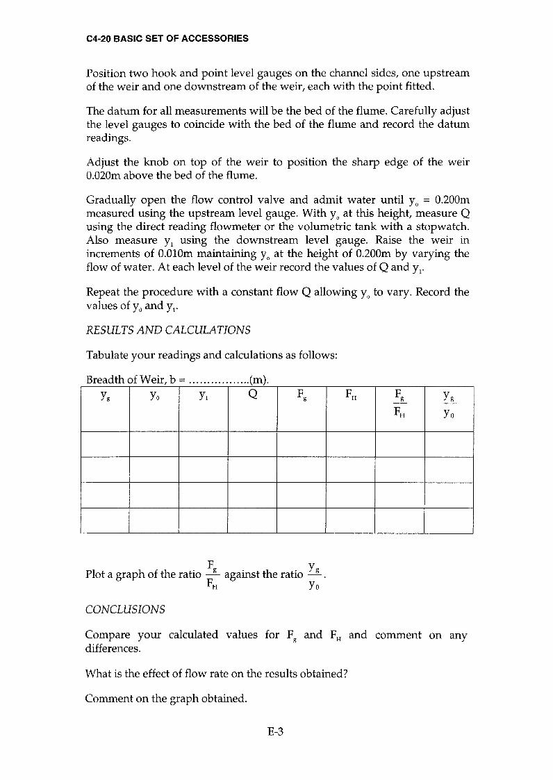
RESULTS AND CALCULATIONS
Tabulate your readings and calculations as follows:
Breadth of weir, b =
.............. ...(m).
yg Yo YI Q Cd Ho HI
D-3
C4-20 BASIC SET OF ACCESSORIES
Plot graphs of Q against Yg for constant Yo and Yo against Yg for constant Q to show the characteristics of flow beneath the weir.
Plot graphs of Cd against Q for constant Yo and Cd against Yg for constant Q to show the changes in Cd of flow beneath the weir.
CONCLUSIONS
Comment on effects of Yo and Q on the discharge coefficient Cd for flow underneath the gate. Which factor has the greatest effect?
Comments on any discrepancies between actual and expected results.
Compare the values obtained for Hl and Ho and comment on any differences.
D-4

C4-20 BASIC SET OF ACCESSORIES
EXPERIMENT E
OBJECTIVE
The force on a Sluice Gate.
OBJECTIVE
To determine the relationship between upstream head and thrust on a sluice gate (undershot weir) for water flowing under the sluice gate.
EQUIPMENT SET-UP
Multi-Purpose Teaching Flume, C4
Adjustable undershot weir Hook and point gauge, 300mm scale - 2 required Stopwatch if measuring flowrate using the volumetric tank (not supplied)
Note: If available, the Pitot tube and manometer, C4-61 (optional accessory)
can be used to measure velocity of the water directly.
Water within control volume
Hydrostatic pressure distribution Q_
Thrust t2 P9Vo2
Non hydrostatic pressure distribution on gate F 9 Hydrostatic pressure
.
distribution
Thrust 1/2 pgY12
Section 0 Sh~ar force Section 1
E-l

Yo
YI
C4-20 BASIC SET OF ACCESSORIES
SUMMARY OF THEORymACKGROUND
It can be shown that the resultant force on the gate is given by the equation:
F g
=
.!. p g y / [y <
- 1] -
p Q [1-~] 2 Yl bYl Yo
The gate thrust for a hydrostatic pressure distribution is gIVen by the equation:
FH= %pg(yo -Ygf
where:
Fg = Resultant gate thrust (N)
(N) FH = Resultant hydrostatic thrust
Q = Volume flowrate (m3 S-I)
= Volume/time (using volumetric tank)
p = Density of fluid (kgm-3)
g
b
= Gravitational constant (9.81m S-2)
= Breadth of gate
= Height of gate opening above bed
= Upstream depth of flow
(m)
(m)
(m)
(m)
Yg
= Downstream depth of flow
PROCEDURE
Note: To save time, the measurements obtained in experiment D can be used to perform the calculations in this experiment. If results are not available proceed as follows:
Ensure the flume is level, with no stop logs installed at the discharge end of the channel. Measure and record the actual breadth b (m) of the undershot weIr.
Clamp the undershot weir assembly securely to the sides of the channel at a
position approximately mid way along the flume with the sharp edge on the bottom of the gate facing upstream. For accurate results the gaps between the weir and the channel should be sealed on the upstream side using Plasticine.
E-2
C4-20 BASIC SET OF ACCESSORIES
Position two hook and point level gauges on the channel sides, one upstream of the weir and one downstream of the weir, each with the point fitted.
The datum for all measurements will be the bed of the flume. Carefully adjust the level gauges to coincide with the bed of the flume and record the datum readings.
Adjust the knob on top of the weir to position the sharp edge of the weir O.020m above the bed of the flume.
Gradually open the flow control valve and admit water until Yo = O.200m measured using the upstream level gauge. With Yo at this height, measure Q using the direct reading flowmeter or the volumetric tank with a stopwatch. Also measure Yl using the downstream level gauge. Raise the weir in increments of O.OlOm maintaining Yo at the height of O.200m by varying the flow of water. At each level of the weir record the values of Q and Yl.
Repeat the procedure with a constant flow Q allowing Yo to vary. Record the values of Yo and Yl.
RESULTS AND CALCULATIONS
Tabulate your readings and calculations as follows:
Breadth of Weir, b = .................(m). Yg Yo Yl Q Fg FH Fg Yg
FH Yo
Plot a graph of the ratio Fg
against the ratio ~. FH Yo
CONCLUSIONS
Compare your calculated values for Fg and FH and comment on any differences.
What is the effect of flow rate on the results obtained?
Comment on the graph obtained.
E-3

C4-20 BASIC SET OF ACCESSORIES
EXPERIMENT F
Critical Depth - Derivation of the Specific Energy Equation.
OBJECTIVE
To determine the relationship between the specific energy and upstream head for water flowing under an undershot weir.
EQUIPMENT SET-UP
Multi-Purpose Teaching Flume, C4
Adjustable undershot weir Hook and point gauge, 300mm scale - 2 required Stopwatch if measuring flowrate using the volumetric tank (not supplied)
Note: If available, the Pitot tube and manometer, C4-61 (optional accessory) can be used to measure velocity of the water directly.
V02
~.. .-1.2.9.... Total energy line
Section 0 Section 1
Yc
Specific Energy Curve
I
Ie
E -
::;:..,.
== C)
::;::: -
C) ...c:: -
CL. <1>
c::l
Ec Specific energy E(m)
F-l

C4-20 BASIC SET OF ACCESSORIES
SUMMARY OF THE ORymACKGR 0 UND
The depth and velocity of a given flow at any section of an open channel adapt themselves to the energy available at that section. For a constant discharge this energy reaches a minimum value at the 'critical' depth. This parameter is fundamental to a complete understanding of free flow behaviour because the response of a stream to energy (and force) depends on whether the actual depth is greater than or less than the critical depth.
In an open channel it is convenient to use the bed as the datum and to compare the specific energy at different sections where the specific energy is defined as the sum of the potential energy (the depth of flow) and the kinetic energy (the velocity head):
V2 E=y+- 2g
Considering unit width of channel the equation becomes:
E=y+ Q2
2gy2
where:
E = Specific energy (m)
(m) y = Depth of flow
Q = Volume flowrate (m3s-1)
= Volume/time (using volumetric tank)
g = Gravitational constant (ms-2)
Note: When the datum coincides with the bed E = H
A plot of specific energy against depth of flow gives a curve called the specific energy curve shown below. The shape of the curve shows that for a
given specific energy there are two possible depths called the alternate depths. At point C on the curve the specific energy is a minimum with only one corresponding depth called the critical depth Yc'
Flow at depths greater than critical is described as 'slow', 'subcritical' or , tranquil' .
Flow at depths less than critical IS described as 'fast', 'supercritical' or 'shooting' .
A family of such curves will exist for different flowrates through the channel.
F-2
C4-20 BASIC SET OF ACCESSORIES
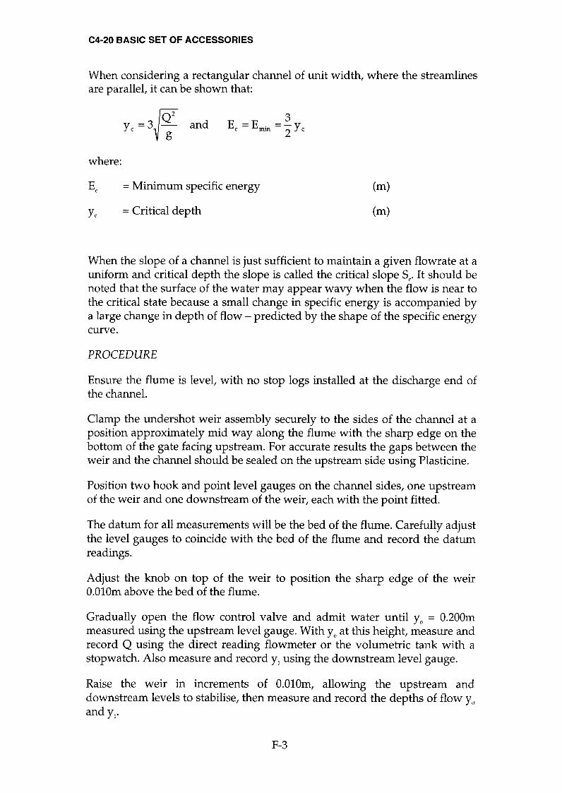
When considering a rectangular channel of unit width, where the streamlines are parallel, it can be shown that:
y, ~3~~2 and 3
E =E . =-y c nun 2c where:
Ec = Minimum specific energy (m)
(m) Yc = Critical depth
When the slope of a channel is just sufficient to maintain a given flowrate at a
uniform and critical depth the slope is called the critical slope Sc. It should be noted that the surface of the water may appear wavy when the flow is near to the critical state because a small change in specific energy is accompanied by a large change in depth of flow - predicted by the shape of the specific energy curve.
PROCEDURE
Ensure the flume is level, with no stop logs installed at the discharge end of the channel.
Clamp the undershot weir assembly securely to the sides of the channel at a
position approximately mid way along the flume with the sharp edge on the bottom of the gate facing upstream. For accurate results the gaps between the weir and the channel should be sealed on the upstream side using Plasticine.
Position two hook and point level gauges on the channel sides, one upstream of the weir and one downstream of the weir, each with the point fitted.
The datum for all measurements will be the bed of the flume. Carefully adjust the level gauges to coincide with the bed of the flume and record the datum readings.
Adjust the knob on top of the weir to position the sharp edge of the weir O.OlOm above the bed of the flume.
Gradually open the flow control valve and admit water until Yo = O.200m measured using the upstream level gauge. With Yo at this height, measure and record Q using the direct reading flowmeter or the volumetric tank with a
stopwatch. Also measure and record Yl using the downstream level gauge.
Raise the weir in increments of O.010m, allowing the upstream and downstream levels to stabilise, then measure and record the depths of flow Yo andYl.
F-3
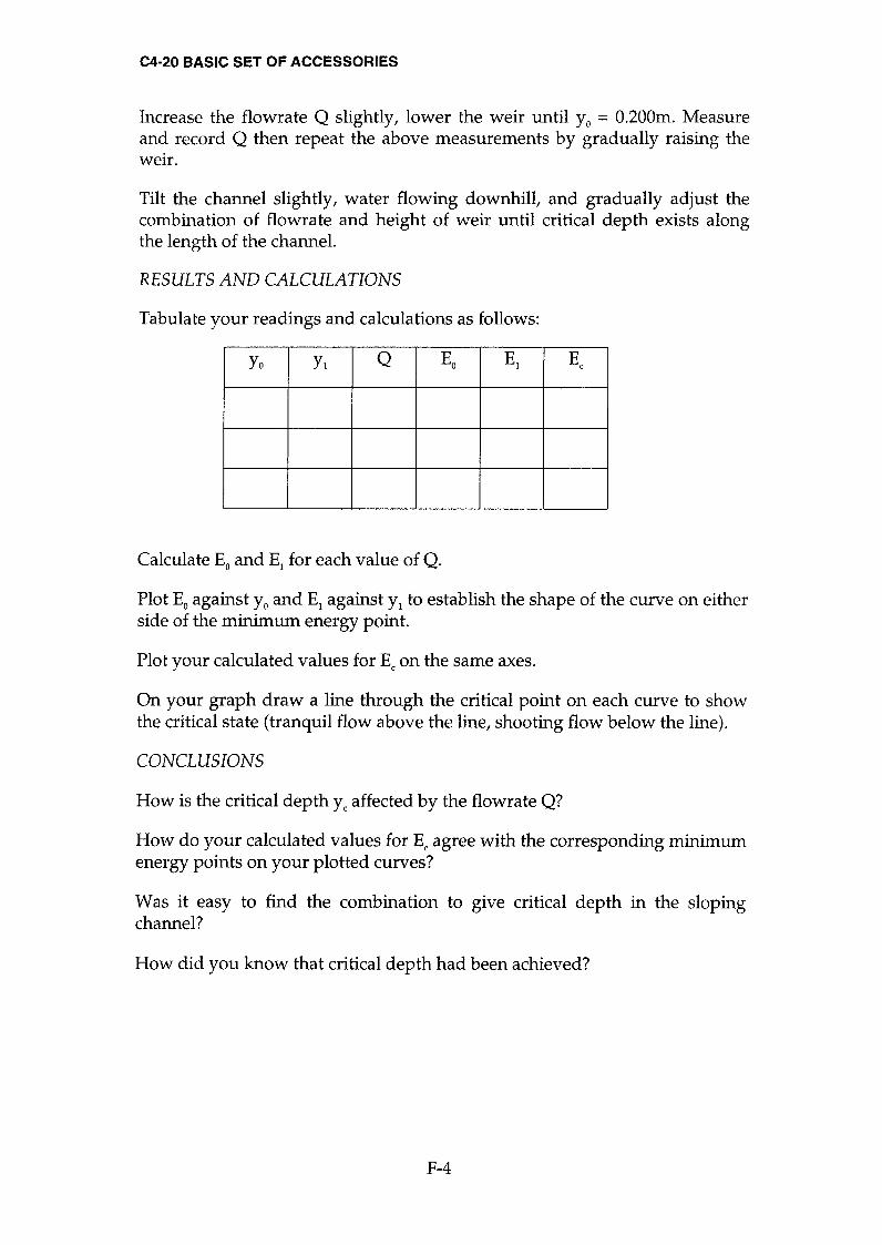
C4-20 BASIC SET OF ACCESSORIES
Increase the flowrate Q slightly, lower the weir until Yo = 0.200m. Measure and record Q then repeat the above measurements by gradually raising the weIr.
Tilt the channel slightly, water flowing downhill, and gradually adjust the combination of flowrate and height of weir until critical depth exists along the length of the channel.
RESULTS AND CALCULATIONS
Tabulate your readings and calculations as follows:
Yo Yl Q Eo El Ec
Calculate Eo and El for each value of Q.
Plot Eo against Yo and El against Yl to establish the shape of the curve on either side of the minimum energy point.
Plot your calculated values for Ec on the same axes.
On your graph draw a line through the critical point on each curve to show the critical state (tranquil flow above the line, shooting flow below the line).
CONCLUSIONS
How is the critical depth Yc affected by the flowrate Q?
How do your calculated values for Ec agree with the corresponding minimum energy points on your plotted curves?
Was it easy to find the combination to give critical depth in the sloping channel?
How did you know that critical depth had been achieved?
F-4

C4-20 BASIC SET OF ACCESSORIES
EXPERIMENT G
The Hydraulic Jump
OBJECTIVE
To investigate the characteristics of a standing wave (the hydraulic jump) produced when water flows beneath an undershot weir and to observe the flow patterns obtained.
EQUIPMENT SET-UP
Multi-Purpose Teaching Flume, C4
Adjustable undershot weir Hook and point gauge, 300mrn scale - 2 required Stopwatch if measuring flowrate using the volumetric tank (not supplied)
Note: If available, the Pitot tube and manometer, C4-61 (optional accessory)
can be used to measure velocity of the water directly.
Total head line Fluctuating water surface c 0 nÎuga-7~ø d
_
h Ii.n~ ) .
I .
.'HI v,} I
"Â _. H~' ..........._
.'.~ _ _ _
U~~.: - +-- I
Section a' Section b Section $'
Water within control volume
G-l

C4-20 BASIC SET OF ACCESSORIES
SUMMARY OF THEORymACKGROUND
When water flowing rapidly changes to slower tranquil flow a hydraulic jump or standing wave is produced. This phenomenon can be seen where water shooting under a sluice gate mixes with deeper water downstream. It occurs when a depth less than critical changes to a depth which is greater than critical and must be accompanied by a loss of energy.
An undular jump occurs when the change in depth is small. The surface of the water undulates in a series of oscillations which gradually decay to a
region of smooth tranquil flow
A direct jump occurs when the change in depth is great. The large amount of energy loss results in a zone of extremely turbulent water before it settles to smooth tranquil flow.
By considering the forces acting within the fluid on either side of a hydraulic jump of unit width it can be shown that:
V2 ( V2J ð.H = Ya +
2 ag - y b + 2 bg
where:
ill = Total head loss across jump (energy dissipated) (m)
Va = Mean velocity before hydraulic jump
Ya = Depth of flow before hydraulic jump
(m S-l)
(m)
Vb = Mean velocity after hydraulic jump (m S-l)
Yb = Depth of flow after hydraulic jump (m)
Because the working section is short Ya ~ Y1 and Yb ~ Y3
Therefore simplifying the above equation:
ð.H = &3 -Yl)3 4YIY3
PROCEDURE
Ensure the flume is level, with no stop logs installed at the discharge end of the channel. Measure and record the actual breadth b (m) of the undershot weIr.
Clamp the undershot weir assembly securely to the sides of the channel close to the upstream end of the flume with the sharp edge on the bottom of the
G-2
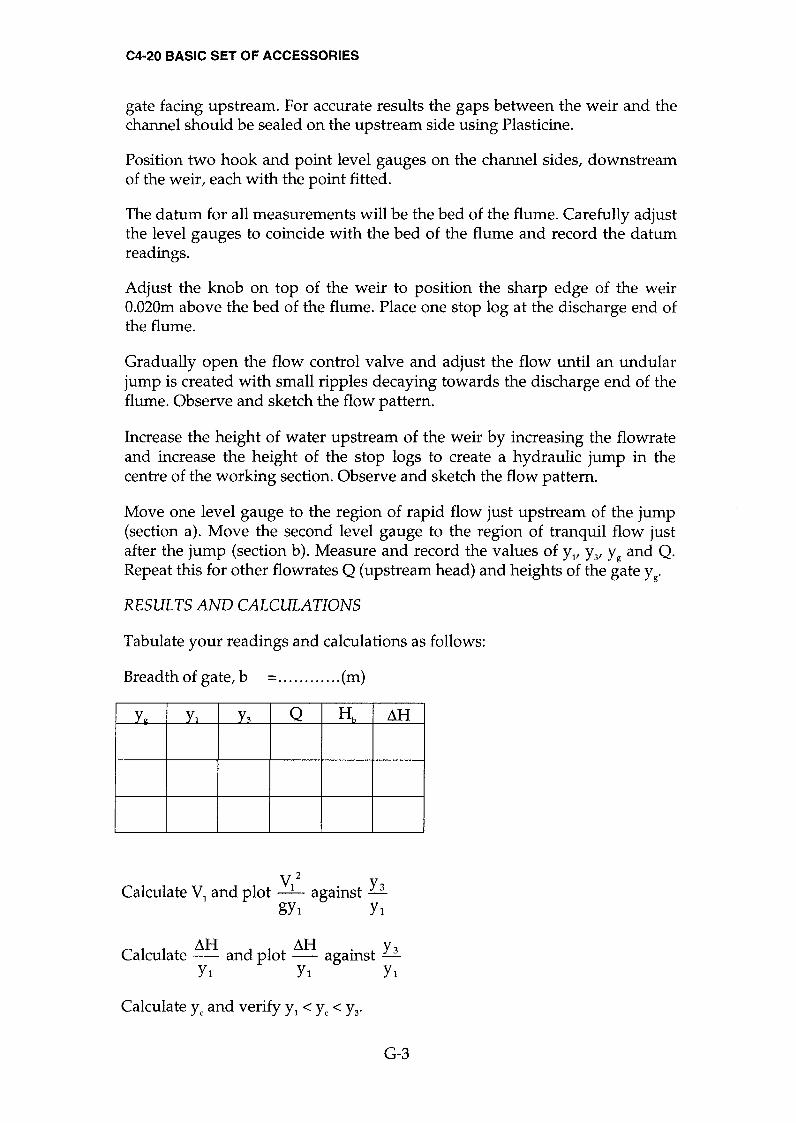
C4-20 BASIC SET OF ACCESSORIES
gate facing upstream. For accurate results the gaps between the weir and the channel should be sealed on the upstream side using Plasticine.
Position two hook and point level gauges on the channel sides, downstream of the weir, each with the point fitted.
The datum for all measurements will be the bed of the flume. Carefully adjust the level gauges to coincide with the bed of the flume and record the datum readings.
Adjust the knob on top of the weir to position the sharp edge of the weir O.020m above the bed of the flume. Place one stop log at the discharge end of the flume.
Gradually open the flow control valve and adjust the flow until an undular jump is created with small ripples decaying towards the discharge end of the flume. Observe and sketch the flow pattern.
Increase the height of water upstream of the weir by increasing the flowrate and increase the height of the stop logs to create a hydraulic jump in the centre of the working section. Observe and sketch the flow pattern.
Move one level gauge to the region of rapid flow just upstream of the jump (section a). Move the second level gauge to the region of tranquil flow just after the jump (section b). Measure and record the values of YI' Y3' Yg and Q. Repeat this for other flowrates Q (upstream head) and heights of the gate Yg'
RESULTS AND CALCULATIONS
Tabulate your readings and calculations as follows:
Breadth of gate, b =............(m)
Yu Yl y~ Q Hh Llli
v2 Calculate VI and plot -L against ~
gyl Yl
Calculate ilH and plot Llli against ~ Yl Yl Yl
Calculate Yc and verify YI < Yc < Y3'
G-3

C4-20 BASIC SET OF ACCESSORIES
CONCLUSIONS
Verify the force of the stream on either side of the jump is the same and that
the specific energy curve predicts a loss equal to AH .
yc
Suggest an application where the loss of energy in hydraulic jump would be desirable. How is the energy dissipated?
G-4

C4-20 BASIC SET OF ACCESSORIES
EXPERIMENT H
Characteristics of flow through a Venturi Flume
OBJECTIVE
To determine the relationship between upstream head and flowrate for water flowing through a Venturi flume; to calculate the discharge coefficient and to observe the flow patterns obtained.
EQUIPMENT SET-UP
Multi-Purpose Teaching Flume, C4
Venturi flume assembly Hook and point gauge, 300mm scale - 2 required Stopwatch if measuring flowrate using the volumetric tank (not supplied)
Note: If available, the Pitot tube and manometer, C4-61 (optional accessory)
can be used to measure velocity of the water directly.
___ . . ___ . . ___ . . ___ . . ___ . . ___ . . ___ . .
j~~IUX
IIDROWNED" CONDmON
. .
-,,-2" .
.....,
-.t.
SUPER CRITICAL CONDmON ~ ~
bO b, Q )
/ ~ b2: bO
PLAN OF FLUME
H-l

C4-20 BASIC SET OF ACCESSORIES
SUMMARY OF THEORyæACKGROUND
By narrowing the sides of a channel, the resulting changes in velocity and depth can be used to calculate the flowrate through the channel.
For modular conditions where the Venturi flume is not drowned, the standing wave equation gives:
3
Q = Cd 1.704 bo H02
where:
Q = Volume flowrate (m3 S-l)
= Volume/time (using volumetric tank)
Cd = Coefficient of discharge (Dimensionless)
b1 = Breadth of throat (m)
(m) Ho = Total head upstream of throat
V02 Q2 = Yo+-=Yo+ (y \2 2 g 2 g 0 bI!
Vo = Mean approach velocity (m S-l)
Yo = Upstream depth of flow (m)
g = Gravitational constant (9.81m S-2)
bo = Breadth of channel upstream (m)
As in the case of the broad crested weir it is more convenient to measure the depth of flow Yo upstream of the throat. The equation can be modified to compensate for the velocity head as follows:
3
Q = Cd Cv 1.704 bI Y 02
Note: Actual coefficients for a full size installation are published in BS3680, Part 4.
The above equations can be applied so long as the flow in some portion of the Venturi flume is supercritical ie. a standing wave is generated.
H-2

C4-20 BASIC SET OF ACCESSORIES
When the Venturi flume becomes drowned, ie. when the flow is sub critical the Bernoulli equation can be applied to give the following relationship:
I
Q~Cd fgl~::2Yl)T .
A m = RatIo of areas =---.!...
Ao
Ao = Flow area upstream = bo Yo
Al = Flow area at throat = bl Y I
PROCEDURE
Ensure the flume is level, with no stop logs installed at the discharge end of the channel. Install the two sections of the Venturi flume in the working section of the channel by standing an asymmetrical insert adjacent to each wall. When correctly positioned the widest part on the two sections should be together and nearer to the inlet end of the channel. Adjust the stretcher bar to hold the two sections firmly against the walls of the flume (the bar must be above the water level). For accurate results the gaps between the Venturi flume and the channel should be sealed on the upstream side using Plasticine.
Measure and record the upstream channel width bo (m) and the throat width bl (m). Gradually open the flow control valve and admit water into the flume.
Maintaining a constant flow, measure and note Yo' Yl and Q. Increase the flow in stages, measuring and noting Yo' Yl and Q for each stage. Observe and sketch the standing wave flow conditions.
Repeat the above measurements with stop logs fitted at the discharge end of the channel, adding one stop log at a time to increase the downstream depth of water and drown the Venturi flume. Observe and sketch the standing wave and drowned flow conditions.
RESULTS AND CALCULATIONS
Tabulate your readings and calculations as follows:
Breadth of throat, bl =........... ..(m)
Yo Yl Q Ho Ao Al m Cd
H-3
C4-20 BASIC SET OF ACCESSORIES
Plot the calibration curve of Q against Yo to show the relationship between flowrate and upstream depth of flow for modular flow conditions.
Plot the graph of Cd against Ho for modular flow conditions.
Calculate the value of C for modular flow conditions. v
Plot the graph of Cd against Ho when the Venturi Flume is drowned.
CONCLUSIONS
Does the coefficient of discharge vary and if so in what manner?
Comment on the effect of narrowing the channel. Is it the same as raising the bed?
What error is introduced if the equations are used on the wrong side of the modular limit?
Would you expect the length of the throat to affect the coefficient of discharge?
If using this Venturi flume to measure flowrate accurately in the channel would you use your calibration curve or calculate the flowrate from the fundamental equation using published data for Cd and why?
H-4

C4-62 CULVERT BLOCK ASSEMBLY
EXPERIMENT J
Characteristics of flow through a Culvert
To determine the characteristics and observe the flow patterns obtained for water flowing through a Culvert with different heads upstream and downstream.
EQUIPMENT SET-UP
Multi-Purpose Teaching Flume, C4
Culvert block assembly, C4-62 (optional accessory) Hook and point gauge, 300mm scale - 2 required Stopwatch if measuring flow rate using the volumetric tank (not supplied)
Culvert block
Channel sides "---
Y1
"-- Flume bed ~
SUMMARY OF THEORymACKGROUND
The culvert is a covered channel of comparatively short length which is
typically installed to drain water through an embankment. The culvert acts as on open channel, as long as the section is partly full, and is normally used in this condition. However, under flood conditions the inlet or outlet may become submerged and a variety of flow patterns can exist. A culvert will run full, like a pipe, when the outlet is submerged or when the upstream level is sufficiently high.
J-l

C4-62 CULVERT BLOCK ASSEMBLY
The objective is to view the range of patterns which can exist, to determine the head/ discharge characteristics and to determine the conditions necessary for the culvert to run full.
The performance of a culvert is defined by the ratio Yo
(typical values are in d the range 1.2 to 1.5 depending on geometry and conditions).
where:
Yo = Depth of flow upstream of the culvert at the point where the (m) culvert runs full
d = Height of the culvert (m)
PROCEDURE
Ensure the flume is level, with no stop logs installed at the discharge end of the channel. Clamp the culvert block securely to the sides of the channel at a
position approximately mid way along the flume with the rounded edge of the culvert facing upstream. For accurate results the gaps between the block and the channel should be sealed on the upstream side using Plasticine. Measure and record the actual breadth b (m) and the height d (m) of the culvert created.
Position two hook and point level gauges on the channel sides, one upstream of the culvert and one downstream of the culvert, each with the point fitted. Record the distance x (m) between the gauges to allow level measurements to be corrected for inclination of the bed. The datum for all measurements will be the bed of the flume. Carefully adjust the level gauges to coincide with the bed of the flume and record the datum readings.
Gradually open the flow control valve and admit the water into the flume. By altering the flow, gradually increase the depth of water upstream of the culvert until the culvert runs full. Observe and sketch the changing profile of the water flow as it passes through the culvert. When running full, measure and record the depth of flow Yo upstream of the culvert, the flow depth Yl downstream and the corresponding flowrate Q.
Drain the culvert, add one stop log at the discharge end of the channel then repeat the above observations and record Yo' Yl and Q when the culvert runs full.
Repeat the procedure adding stop logs at the discharge end until the culvert remains full with no flow.
Remove the stop logs, drain the culvert then incline the channel bed slightly (flow downhill). Gradually increase the flowrate until the channel runs full as before then record Yo' Yl' Q and S (slope of the bed).
J-2

C4-62 CULVERT BLOCK ASSEMBL V
Repeat the procedure for increasing slope of the channel bed.
If time permits repeat the above experiment for a different height of culvert by adjusting the vertical position of the culvert block. The change in flow profile when the square comer is positioned upstream could also be investigated.
RESULTS AND CALCULATIONS
Tabulate your readings and calculations as follows:
Breadth of culvert, b =............ .(m)
Height of culvert, d =...... ...... ..(m)
Yo Yl Q s yold
CONCLUSIONS
How many different profiles did you observe as flow through the culvert changes from partial to full flow?
What is your value for X2..
when the exit is not submerged? d
How does this ratio change when the exit becomes submerged?
How does the slope affect the performance of the culvert?
Are there any similarities between the culvert and the undershot weir and if so under what conditions of flow do they occur?
J-3

C4-63 FLOW SPLITTERS ASSEMBLY
EXPERIMENT K
Characteristics offlow around Flow Splitters
OBJECTIVE
To observe the flow patterns obtained for water flowing around splitters with different profiles.
EQUIPMENT SET-UP
Multi-Purpose Teaching Flume, C4
Flow splitters, C4-63 (optional accessory) Hook and point gauge, 300mm scale - 2 required Stopwatch if measuring flowrate using the volumetric tank (not supplied)
Note: If available, the Pitot tube and manometer, C4-61 (optional accessory) can be used to measure velocity of the water directly.
b1,ltr b1
Channel21l rl2 sides "-
"-- Flume bed Flow splitters (interchangeable sections) bo
Plasticine for smoother transition
SUMMARY OF THE OR ymA CKGR 0 UND
The flow splitter represents an obstruction in an open channel which would typically represent the pier of a bridge, the support structure on the top of a
dam spillway etc. The effect of the obstruction is similar to a constriction but the flow is split into two streams instead of one.
K-l

C4-63 FLOW SPLITTERS ASSEMBLY
The obstruction causes a disturbance to the flow and turbulence is created where the two streams mix resulting in head loss. This head loss also produces a force on the object known as form drag.
The magnitude of the losses and forces depends on the shape of the obstruction and the degree of narrowing of the channel.
The objective is to view the disturbances caused by the splitter and to determine the headloss/ discharge characteristics.
The performance of an obstruction can be defined by the d' Aubuisson formula which states:
I
Q = K A bl Y 2
(2 g h2 + Vo 2 )2
where:
Q = Volume flowrate (m3s-I)
KA = Coefficient of contraction (Dimensionless)
bI = Remaining width of channel at obstruction (m)
(m)
(m)
(m)
Y2 = Depth of flow downstream of obstruction
~ = Height of backwater = YO-Y2
Vo = Mean upstream velocity
g = Gravitational constant (9.81m S-2)
PROCEDURE
Ensure the flume is level, with no stop logs installed at the discharge end of the channel. Measure the width of the channel bo (m) and the thickness of the splitter t (m).
Position the model flow splitter mid way along the channel with the rounded end upstream. Use Plasticine to form a smooth transition at each end of the base plate.
Position two hook and point level gauges on the channel sides, one upstream of the splitter and one downstream of the splitter, each with the point fitted. The datum for all measurements will be the bed of the flume. Carefully adjust the level gauges to coincide with the bed of the flume and record the datum readings.
K-2
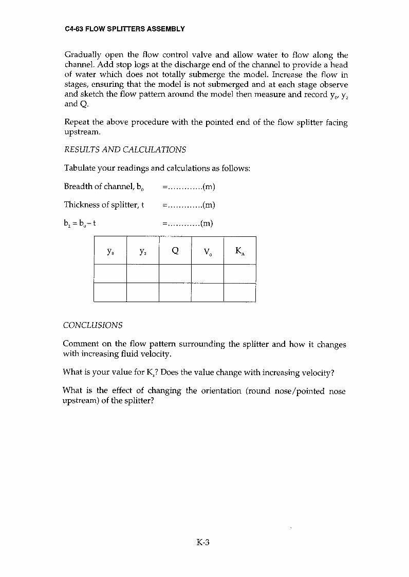
C4-63 FLOW SPLITTERS ASSEMBLY
Gradually open the flow control valve and allow water to flow along the channel. Add stop logs at the discharge end of the channel to provide a head of water which does not totally submerge the model. Increase the flow in stages, ensuring that the model is not submerged and at each stage observe and sketch the flow pattern around the model then measure and record Yo' yz andQ.
Repeat the above procedure with the pointed end of the flow splitter facing upstream.
RESULTS AND CALCULATIONS
Tabulate your readings and calculations as follows:
Breadth of channel, bo =......... ....(m)
=............ .(m)
=............(m)
Thickness of splitter, t
bz = bo-t
Yo yz Q Vo KA
CONCLUSIONS
Comment on the flow pattern surrounding the splitter and how it changes with increasing fluid velocity.
What is your value for Ka? Does the value change with increasing velocity?
What is the effect of changing the orientation (round nose/pointed nose upstream) of the splitter?
K-3
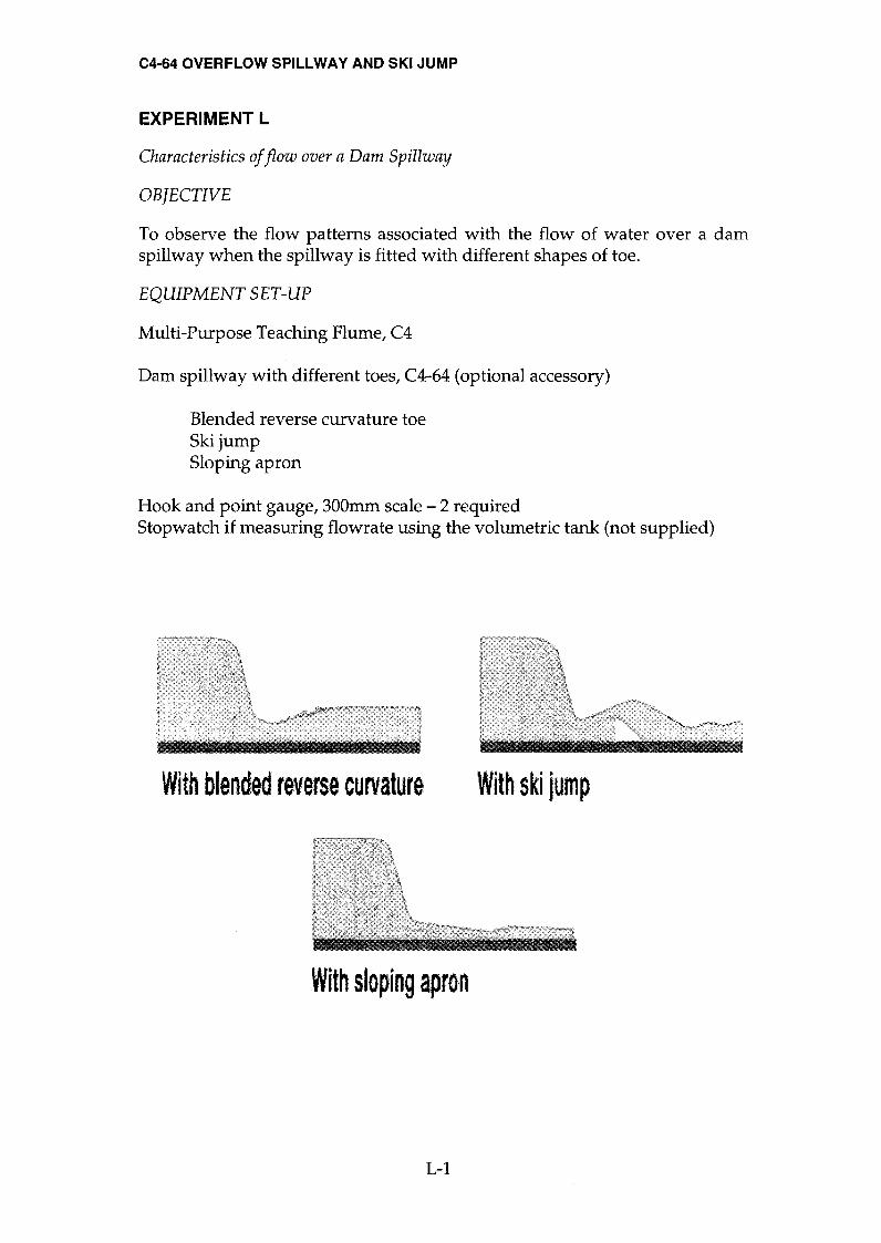
C4-64 OVERFLOW SPILLWAY AND SKI JUMP
EXPERIMENT L
Characteristics of flow over a Dam Spillway
OBJECTIVE
To observe the flow patterns associated with the flow of water over a dam spillway when the spillway is fitted with different shapes of toe.
EQUIPMENT SET-UP
Multi-Purpose Teaching Flume, C4
Dam spillway with different toes, C4-64 (optional accessory)
Blended reverse curvature toe Ski jump Sloping apron
Hook and point gauge, 300mm scale - 2 required Stopwatch if measuring flowrate using the volumetric tank (not supplied)
With blended reverse curvature With ski jum p
With sloping apron
L-l

C4-64 OVERFLOW SPILLWAY AND SKI JUMP
PROCEDURE
Ensure the flume is level, with no stop logs installed at the discharge end of the channel. Place the dam spillway in the flume towards the inlet end of the
working section with the crest facing upstream and the blended reverse curvature toe located beneath the lip. Ensure that the spillway is secured using a mounting hook through the bed of the flume. For accurate results the gaps between the spillway and the channel should be sealed on the upstream side using Plasticine.
Position two hook and point level gauges on the channel sides, one upstream of the spillway, the second downstream, each with the point fitted. The datum for all measurements will be the bed of the flume. Carefully adjust the level gauges to coincide with the bed of the flume and record the datum readings.
The above diagrams show the patterns of water flowing over a dam spillway when different shaped toes are fitted downstream. The flow over each version of the dam spillway should be varied in stages, by adjusting the flow control valve, and at each stage the flow pattern should be observed and sketched and the flowrate, upstream and downstream water levels recorded.
Note: When using the ski jump it should be retained using the stretcher screw provided.
The downstream depth of water should then be varied in stages, by adding stop logs at the discharge end of the channel, to investigate the effect on the flow patterns. Observe and sketch the modified flow pattern at each stage as the downstream depth is increased.
CONCLUSIONS
Compare the various flow characteristics and relate these to problems which may occur in everyday practice, ego erosion of the structure, scouring of the river bed, foaming of the water etc.
Comment on the different methods of dissipating the kinetic energy of the water. Which method is the most effective?
L-2

C4-65 SYPHON SPILLWAY AND SELF REGULATING SYPHON
EXPERIMENT M
Characteristics of flow through a Siphon Spillway
OBJECTIVE
To determine the relationship between upstream head and flowrate through a
siphon spillway in the "blackwater" fully primed condition, to calculate the discharge coefficient and to observe the operation of the siphon as it primes and de-primes.
EQUIPMENT SET-UP
Multi-Purpose Teaching Flume, C4
Siphon spillway, C4-65 (optional accessory) Hook and point gauge, 300mm scale - 2 required Stopwatch if measuring flowrate using the volumetric tank (not supplied)
Deflecti"l) nappe
h
Throat
SUMMARY OF THEORY
The traditional siphon spillway is shown in the above diagram and consists of a weir with a crest which is covered by a hood to create a barrel. In normal operation the inlet and outlet are both submerged so that air cannot enter the barrel from the outside atmosphere.
M-l

C4-65 SYPHON SPILLWAY AND SELF REGULATING SYPHON
No flow of water can occur until the upstream level rises above the crest. Flow then spills over in much the same way as a normal weir. As the level rises further the velocity increases and the falling nappe, assisted by a
deflector in the down-leg, entrains and removes air from inside the barrel. As the barrel becomes sealed, air cannot enter from outside so the pressure falls -
increasing the flow rate until the barrel is running full of water. At this stage the siphon is said to be primed and the flow condition is called "blackwater flow" because no air is entrained in the water. (Entrained air gives the water a
milky appearance.)
During priming the discharge increases rapidly from zero to full capacity. Any further rise in the upstream level has little effect on the flowrate through the siphon, only increasing it slightly.
Provided that the flow through the siphon is in excess of the flow into the channel, the upstream level will continue to fall, even when the level falls below the top of the crest. The siphon will stop acting when the level falls below the hood and air enters the barrel. The accompanying fall in flowrate through the siphon will cause the upstream level to rise again and the siphon
will prime again. This cycle will continue until the flowrate upstream reduces.
To achieve closer control of the level upstream a siphon breaker (breather tube) can be fitted to the top of the hood above the crest. By positioning the free end of the tube just above the crest of the weir the change in level between the primed and de-primed condition can be minimised.
M-2
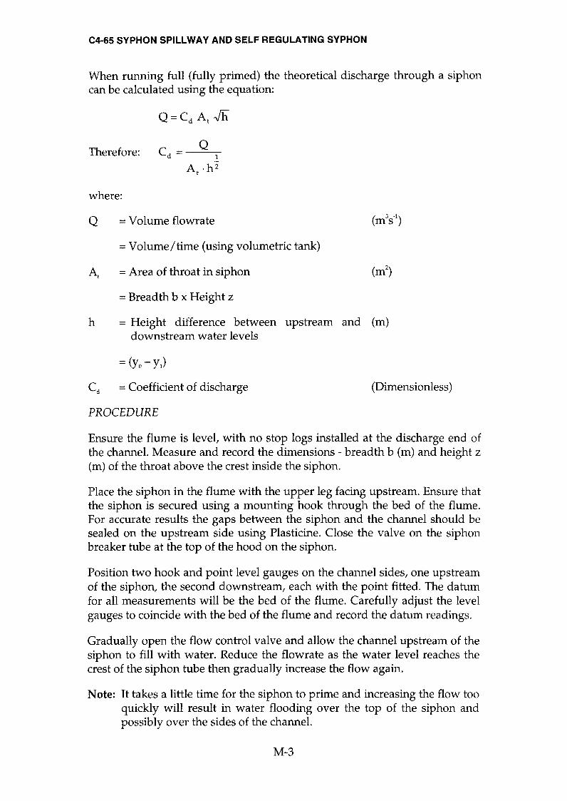
C4-65 SYPHON SPILLWAY AND SELF REGULATING SYPHON
When running full (fully primed) the theoretical discharge through a siphon
can be calculated using the equation:
Q=Cd At Jh
Therefore: Q
Cd = 1
At .h2
where:
Q = Volume flowrate (m3s-1)
= Volume/time (using volumetric tank)
At = Area of throat in siphon (m2)
= Breadth b x Height z
h = Height difference between upstream and (m) downstream water levels
= (Yo - Yl)
Cd = Coefficient of discharge (Dimensionless)
PROCEDURE
Ensure the flume is level, with no stop logs installed at the discharge end of the channel. Measure and record the dimensions - breadth b (m) and height z
(m) of the throat above the crest inside the siphon.
Place the siphon in the flume with the upper leg facing upstream. Ensure that the siphon is secured using a mounting hook through the bed of the flume. For accurate results the gaps between the siphon and the channel should be sealed on the upstream side using Plasticine. Close the valve on the siphon breaker tube at the top of the hood on the siphon.
Position two hook and point level gauges on the channel sides, one upstream of the siphon, the second downstream, each with the point fitted. The datum for all measurements will be the bed of the flume. Carefully adjust the level gauges to coincide with the bed of the flume and record the datum readings.
Gradually open the flow control valve and allow the channel upstream of the siphon to fill with water. Reduce the flowrate as the water level reaches the crest of the siphon tube then gradually increase the flow again.
Note: It takes a little time for the siphon to prime and increasing the flow too quickly will result in water flooding over the top of the siphon and possibly over the sides of the channel.
M-3

C4-65 SYPHON SPILLWAY AND SELF REGULATING SYPHON
Allow the upstream and downstream channels to fill so that both the siphon inlet and outlet are submerged. If the outlet is not submerged add stop logs at the exit from the channel until the outlet just remains submerged.
If necessary adjust the flow control valve so that the upstream water level falls slowly when the siphon has fully primed.
Observe the level changes upstream and the operation of the siphon as it primes and de-primes in a continuous cycle. Observe that the water level falls below the crest and does not de-prime until the hood is exposed and air enters the barrel.
Position the end of the siphon breaker (breather tube) so that it is just above the level of the crest then open the valve on the tube. Observe that the siphon action breaks when the end of the tube is exposed to the air resulting in a
much smaller change in the upstream level.
Close the valve on the siphon breaker. When the siphon is primed increase the flow by adjusting the flow control valve so that the upstream level remains constant. When conditions are stable measure the upstream level Yo and the downstream level Yl using the level gauges then measure the volume flowrate Q using the direct reading flowmeter or volumetric tank with a
stopwatch.
With the siphon still fully primed, gradually raise the tailwater level by increasing the number of stop logs. When each change has stabilised measure Yo' Yl and Q.
RESULTS AND CALCULATIONS
Tabulate your readings and calculations as follows:
Breadth of throat, b.............. .(m)
Height of throat, z...... ... ... .....(m)
Area of throat, At..... ...... .... ...(m2)
Yo Yl h Q Cd
Calculate the coefficient of discharge Cd'
M-4

C4-65 SYPHON SPILLWAY AND SELF REGULATING SYPHON
CONCLUSIONS
What are the advantages and disadvantages of siphon spillways ("blackwater" siphons)?
What is the function of the deflecting nappe?
M-5

C4-65 SYPHON SPILLWAY AND SELF REGULATING SYPHON
EXPERIMENT N
Characteristics of flow through an Air Regulated Siphon
OBJECTIVE
To determine the relationship between upstream head and flowrate through an air regulated siphon, to calculate the discharge coefficient and to observe the operation of the siphon as it primes and de-primes.
EQUIPMENT SET-UP
Multi-Purpose Teaching Flume, C4
Air regulated siphon, C4-65 (optional accessory) Hook and point gauge, 300mm scale - 2 required Stopwatch if measuring flowrate using the volumetric tank (not supplied)
h
Deflecting nappe
SUMMARY OF THEORY
The air-regulated siphon is a more recent development than the traditional siphon demonstrated in experiment M. It will automatically adjust its discharge over a wide range while maintaining a relatively constant water level upstream. This is achieved by the siphon passing a mixture of air and water continuously. The upstream level is more stable and not prone to hunting.
N-l
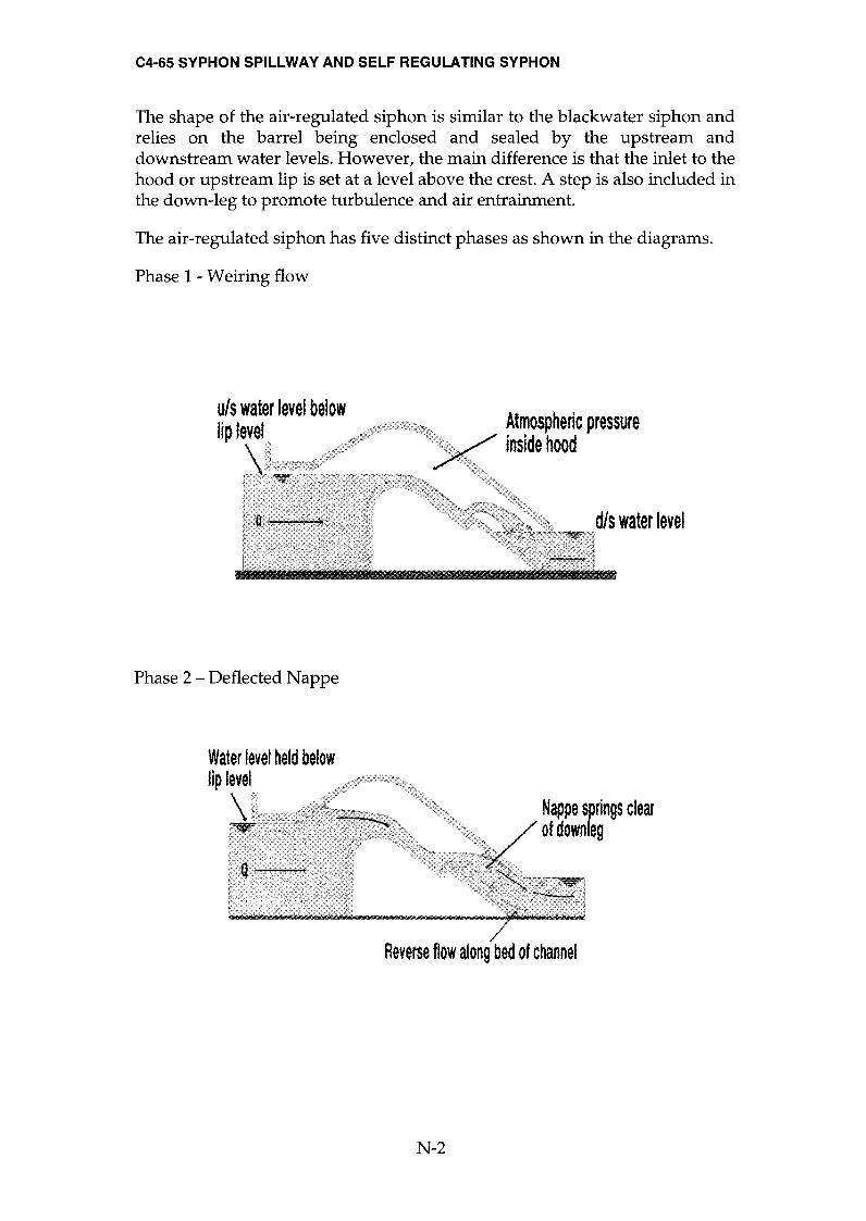
C4-65 SYPHON SPILLWAY AND SELF REGULATING SYPHON
The shape of the air-regulated siphon is similar to the blackwater siphon and relies on the barrel being enclosed and sealed by the upstream and downstream water levels. However, the main difference is that the inlet to the hood or upstream lip is set at a level above the crest. A step is also included in the down-leg to promote turbulence and air entrainment.
The air-regulated siphon has five distinct phases as shown in the diagrams.
Phase 1 - We iring flow
uls water level below lip level Atmospheric pressure
inside hood
Phase 2 - Deflected Nappe
Water level held below lip level
Nappe springs clear of down leg
Reverse flow along bed of channel
N-2

C4-65 SYPHON SPILLWAY AND SELF REGULATING SYPHON
Phase 3 - Depressed Nappe
Locolised drowdown of surfoæ water Noppe dings
to downleg
Phase 4 - Air Partialised
v
More pronounced locolsed drowdown
Air bubbles trovel along underside of hood
Reverse surface
current
Phase 5 - "Blackwater" Flow
Su!.shlluiøl rise in
u/s wtße( ImI
N-3
C4-65 SYPHON SPILLWAY AND SELF REGULATING SYPHON
The transition from one phase to another is quite gradual and there is no distinct or abrupt change over point.
When running full (Phase 5 - blackwater flow) the theoretical discharge through the air-regulated siphon is the same as the blackwater siphon and can be calculated using the equation:
Q=Cd At Æ
Therefore: Q
Cd = 1
At h2
where:
Q = Volume flowrate (m3s'1)
= Volume/time (using volumetric tank)
At = Area of throat in siphon (m2)
= Breadth b x Height z
h = Height difference between upstream and downstream (m) water levels
= (Yo - y) Cd = Coefficient of discharge (Dimensionless)
PROCEDURE
Ensure the flume is level, with no stop logs installed at the discharge end of the channel. Measure and record the dimensions - breadth b (m) and height z
(m) of the throat above the crest inside the siphon.
Place the siphon in the flume towards the inlet end of the working section with the upper lip facing upstream. Ensure that the siphon is secured using a
mounting hook through the bed of the flume. For accurate results the gaps between the siphon and the channel should be sealed on the upstream side using Plasticine.
Position two hook and point level gauges on the channel sides, one upstream of the siphon, the second downstream, each with the point fitted. The datum for all measurements will be the bed of the flume. Carefully adjust the level gauges to coincide with the bed of the flume and record the datum readings.
Gradually open the flow control valve and allow the channel upstream of the siphon to fill with water. Reduce the flowrate as the water level reaches the crest of the siphon tube then gradually increase the flow again.
N-4

C4-65 SYPHON SPILLWAY AND SELF REGULATING SYPHON
Open the inlet valve and gradually increase the flow to the siphon taking great care not to overload the siphon. It takes a little time for the siphon to prime and increasing the flow too quickly will cause the flow to flood over the top of the siphon. Gradually allow the downstream channel to fill with water so that the siphon outlet is submerged. Add stop logs if necessary until the hood at the outlet of the siphon is just submerged.
Adjust the flow control valve to a very low flow and observe the free weiring flow. Increase the flowrate so that the upstream water level rises and seals the inlet.
Observe the priming action and deflected nappe flow as air is drawn in through the inlet and evacuated through the outlet. Increase the flow and observe the gradual change to the depressed nappe flow. At certain flows the siphon may alternate between deflected nappe and depressed nappe flow.
Increase the flow further and observe the air partialised and "blackwater" flow conditions. Because of the increased flow the downstream water level will have risen above the original priming level. To ensure a vigorous air flow, gradually lower the tailwater level by removing stop logs as the flow increases but make sure the outlet is always drowned.
While operating in the blackwater condition measure the upstream level Yo and the downstream level Yl using the level gauges then measure the volume flowrate Q using the direct reading flowmeter or volumetric tank with a
stopwatch.
Observe the effect of different tailwater levels on the initial priming action and on air regulation for the different flow phases.
RESULTS AND CALCULATIONS
Tabulate your readings and calculations as follows:
Breadth of throat, b =........... .(m)
Height of throat, z =........... .(m)
Area of throat At =......... ....(m2)
Yo Yl h Q Cd
N-5

C4-65 SYPHON SPILLWAY AND SELF REGULATING SYPHON
Calculate the coefficient of discharge Cd for the "blackwater" flow condition.
Plot the stage discharge characteristics.
CONCLUSIONS
What is the function of the deflecting nappe in the conduit?
N-6

C4-66 MODEL RADIAL GATE ASSEMBLY
EXPERIMENT P
Characteristics of flow under a Radial Gate
OB]ECTNE
To determine the relationship between upstream head and flowrate beneath a
radial gate (Tainter Gate) under different operating conditions and to calculate the discharge coefficient in each condition.
EQUIPMENT SET-UP
Multi-Purpose Teaching Flume, C4
Radial gate assembly, C4-66 (optional accessory) Hook and point gauge, 300mm scale - 2 required Stopwatch if measuring flowrate using the volumetric tank (not supplied)
Note: If available, the Pitot tube and manometer, C4-61 (optional accessory)
can be used to measure velocity of the water directly.
P-l
C4-66 MODEL RADIAL GATE ASSEMBLY
SUNUWARYOFTHEORymACKGROUND
For an underflow gate with free discharge:
Q = Cd A .J2 g Yo
where:
Q = Volume flowrate (m3s-1)
= Volume/time (using volumetric tank)
Cd = Overall coefficient of discharge
A = Area of the opening
(Dimensionless)
(m2)
= b breadth x height of gate opening Ya
= Upstream depth of flow (m) Yo
g = Gravitational constant (ms-2)
Note: If the downstream side is submerged then Yo is replaced with (Yo-Yl) in the above equation.
PROCEDURE
Clamp the radial gate assembly securely to the sides of the channel then level the flume. Adjust the screw on the top of the gate to create a small gap between the bottom of the gate and the bed of the channel. Gradually open the flow control valve and allow the flow to stabilise without the water flowing over the gate.
With the flow constant, measure and note the values of Q, Yg and Yo' Raise the gate in increments, measuring and noting the values of Q, Yg and Yo for each step.
The procedure should be repeated with a varying flow and constant Yo thus obtaining a further set of results.
Stop logs can be added at the discharge end of the channel to submerge the discharge side of the gate. Measurements should include the downstream level in the flume.
P-2

C4-66 MODEL RADIAL GATE ASSEMBLY
RESULTS AND CALCULATIONS
Tabulate your readings and calculations as follows:
Breadth of gate b, =............(m)
Yo Yl Yg Q A Cd
Plot Cd against ha
for constant Q. ho
Plot Cd against ~ for constant ~. ho
CONCLUSIONS
Comment on the effects of Yo and Q on the discharge underneath the gate. Which factor has the greatest effect?
Comment on discrepancies between actual and expected results.
P-3

C4-68 FALSE FLOOR SECTIONS
EXPERIMENT Q
Characteristics of flow over False Floor Sections
OBJECTNE
To observe the flow patterns associated with the flow of water over different bed profiles.
EQUIPMENT SET-UP
Multi-Purpose Teaching Flume, C4
False floor sections, C4-68 (optional accessory) Hook and point gauge, 300mm scale - 2 required Stopwatch if measuring flowrate using the volumetric tank (not supplied)
Note: If available, the Pitot tube and manometer, C4-61 (optional accessory)
can be used to measure velocity of the water directly.
Lamio!ated ramp (3 semons)
Parallel face sectioD End ramp
Porallel focesedion
Q-l

C4-68 FALSE FLOOR SECTIONS
PROCEDURE
The above diagrams show the correct assembly of the three different arrangements of the floor sections. Set up the laminated ramp in the flume ensuring that the flume is level. Open the flow control valve and allow the water to enter the flume. By adjusting the valve, the depth of water can be varied in stages. At each stage the flow pattern of the water should be observed and noted.
The critical depth can be determined as a separate experiment (refer to Experiment F for details of the theory and calculations).
Since the ramp is fabricated in three sections the above procedure can be repeated with the different profiles.
Close the flow control valve, allow the water to drain from the flume then replace the laminated ramp with the false floor. Repeat the above.
Close the flow control valve, allow the water to drain from the flume then replace the false floor with the raised floor. Repeat the above.
CONCLUSIONS
Compare the flow patterns obtained with each of the different floor sections.
Is there any similarity with the flow patterns obtained when using the Broad Crested Weir?
Q-2

C4-69 ARTIFICIALLY ROUGHENED BED
EXPERIMENT R
Characteristics of flow over a Gravel Bed
OBJECTIVE
To determine the effect of a roughened bed on the depth of water at different
flowrates and to obtain appropriate coefficients to satisfy the Manning
Formula.
EQUIPMENT SET-UP
Multi-Purpose Teaching Flume, C4
Artificially roughened bed, C4-69 (optional accessory) Hook and point gauge, 300mm scale - 2 required Stopwatch if measuring flowrate using the volumetric tank (not supplied)
x
Note: If available, the Pitot tube and manometer, C4-61 (optional accessory) can be used to measure velocity of the water directly.
R-1
C4-69 ARTIFICIALLY ROUGHENED BED
SUNßÆARYOFTHEORY$ACKGROUND
For uniform flow in an open channel the Manning Formula states that:
V =(~)R~S~ where:
n = Coefficient of roughness (Manning's n)
V = Mean fluid velocity
R = Hydraulic mean radius
= Flow area A (m2)/Wetted perimeter P (m)
S = Slope of energy line = Sin e = (Yu - Yd)/X
(Dimensionless)
(ms-1)
(m)
(m)
(Dimensionless)
Yo = Upstream depth of flow
Yl = Downstream depth of flow
(m)
(m)
(m)
x = Distance between level measurements
Note: For simplicity the slope S can be assumed to be the slope of the water
surface if the small change in the velocity head between inlet and outlet is ignored. When using the flume with the bed inclined, the slope
of the bed must be added to calculations of S when using the hook and
point gauges which use the bed as a datum.
The actual fluid velocity can be calculated as follows:
V=Q A
(ms-1)
where:
V
Q
= Mean fluid velocity
= Volume flowrate
(ms-1)
(m3s-1)
h
= Volume/time (using volumetric tank)
= Average depth of flow above gravel bed
= (Yo + Yl)/2
A = Area of flow
(m)
(m)
(m2)
= Breadth of channel b (m) x depth of flow h (m)
R-2

C4-69 ARTIFICIALLY ROUGHENED BED
PROCEDURE
Line the bottom of the flume with the gravel bed sections. To stop them
sliding clamp the stretcher screw between the channel side walls at the
downstream end. Level the flume by adjusting the jack if necessary.
Position a hook and point level gauge on the side walls at each end of the
channel and record the fixed distance apart x (m). The datum for all
measurements will be the average height of the roughened bed. Carefully
adjust the level gauges to coincide with the top of the bed and record the
datum readings.
Ensure that no stop logs are fitted at the downstream end then open the flow
control valve and admit the water into the flume. Having achieved a small
head of flowing water above the gravel, do not adjust the flow control valve
again to maintain a constant flowrate throughout the experiment. Measure the
volume flowrate Q using the direct reading flowmeter or volumetric tank with
stopwatch. Adjust the level gauges to coincide with the surface of the water
then record the depth of flow Yo and Yl above the roughened bed at each end.
Fit one stop log to increase the depth of water and repeat the measurements.
Continue adding stop logs, recording the measurements for each step.
Further sets of readings can be obtained by repeating the above
measurements with a different flowrate or with the bed of the flume sloping.
RESULTS AND CALCULATIONS
Tabulate your readings and calculations as follows:
Distance between level gauges, x=............(m)
Q Yo Yl h x S A P V R n
Calculate A, V, Sand R then determine n using the Manning Formula for
each condition.
R-3

C4-69 ARTIFICIALLY ROUGHENED BED
CONCLUSIONS
How accurate is the n value obtained likely to be?
Does the value of n obtained vary with flow conditions in the flume?
Comment on the suitability of your values for n when calculating fluid velocity
along a meandering river with a gravel bed.
R-4
GENERAL SAFETY RULES
1. Follow Relevant Instructions
a. Before attempting to install, commISSIOn or operate equipment, all relevant suppliers' I manufacturers' instructions and local regulations should be understood and implemented.
b. It is irresponsible and dangerous to misuse equipment or ignore instructions, regulations or warnings.
c. Do not exceed specified maximum operating conditions (eg. temperature, pressure, speed etc.).
2. Installation
a. Use lifting tackle where possible to install heavy equipment. Where manual lifting is necessary beware of strained backs and crushed toes. Get help from an assistant if necessary. Wear safety shoes where appropriate.
b. Extreme care should be exercised to avoid damage to the equipment during handling and unpacking. When using slings to lift equipment, ensure that the slings are attached to structural framework and do not foul adjacent pipework, glassware etc. When using fork lift trucks, position the forks beneath structural framework ensuring that the forks do not foul adjacent pipework, glassware etc. Damage may go unseen during commissioning creating a potential hazard to subsequent operators.
c. Where special foundations are required follow the instructions provided and do not improvise. Locate heavy equipment at low level.
d. Equipment involving inflammable or corrosive liquids should be sited in a containment area or bund with a capacity 50% greater than the maximum equipment contents.
e. Ensure that all services are compatible with the equipment and that independent isolators are always provided and labelled. Use reliable connections in all instances, do not improvise.
f. Ensure that all equipment is reliably earthed and connected to an electrical supply at the correct voltage. The electrical supply must incorporate a Residual Current Device (RCD) (alternatively called an Earth Leakage Circuit Breaker - ELCB) to protect the operator from severe electric shock in the event of misuse or accident.
g. Potential hazards should always be the first consideration when deciding on a suitable location for equipment. Leave sufficient space between equipment and between walls and equipment.
a

3. Commissioning
a. Ensure that equipment is commissioned and checked by a competent member of staff before permitting students to operate it.
4. Operation
a. Ensure that students are fully aware of the potential hazards when operating equipment.
b. Students should be supervised by a competent member of staff at all times when in the laboratory. No one should operate equipment alone. Do not leave equipment running unattended.
c. Do not allow students to derive their own experimental procedures unless they are competent to do so.
d. Serious injury can result from touching apparently stationary equipment when using a stroboscope to 'freeze' rotary motion.
5. Maintenance
a. Badly maintained equipment is a potential hazard. Ensure that a
competent member of staff is responsible for organising maintenance and repairs on a planned basis.
b. Do not permit faulty equipment to be operated. Ensure that repairs are carried out competently and checked before students are permitted to operate the equipment.
6. Using Electricity
a. At least once each month, check that ELCB's (RCCBs) are operating correctly by pressing the TEST button. The circuit breaker must trip when the button is pressed (failure to trip means that the operator is
not protected and a repair must be effected by a competent electrician before the equipment or electrical supply is used).
b. Electricity is the commonest cause of accidents in the laboratory. Ensure that all members of staff and students respect it.
e. Ensure that the electrical supply has been disconnected from the equipment before attempting repairs or adjustments.
d. Water and electricity are not compatible and can cause serious injury if they come into contact. Never operate portable electric appliances adjacent to equipment involving water unless some form of constraint or barrier is incorporated to prevent accidental contact.
e. Always disconnect equipment from the electrical supply when not in use.
b
7. Avoiding tires or explosion
a. Ensure that the laboratory is provided with adequate fire extinguishers appropriate to the potential hazards.
b. Where inflammable liquids are used, smoking must be forbidden. Notices should be displayed to enforce this.
c. Beware since fine powders or dust can spontaneously ignite under certain conditions. Empty vessels having contained inflammable liquids can contain vapour and explode if ignited.
d. Bulk quantities of inflammable liquids should be stored outside the laboratory in accordance with local regulations.
e. Storage tanks on equipment should not be overfilled. All spillages should be immediately cleaned up, carefully disposing of any contaminated cloths etc. Beware of slippery floors.
f. When liquids giving off inflammable vapours are handled in the laboratory, the area should be ventilated by an ex-proof extraction system. Vents on the equipment should be connected to the extraction system.
g. Students should not be allowed to prepare mixtures for analysis or other purpose without competent supervision.
8. Handling poisons, corrosive or toxic materials
a. Certain liquids essential to the operation of equipment, for example mercury, are poisonous or can give off poisonous vapours. Wear appropriate protective clothing when handling such substances. Clean up any spillage immediately and ventilate areas thoroughly using extraction equipment. Beware of slippery floors.
b. Do not allow food to be brought into or consumed in the laboratory. Never use chemical beakers as drinking vessels.
c. Where poisonous vapours are involved, smoking must be forbidden. Notices should be displayed to enforce this.
d. Poisons and very toxic materials must be kept in a locked cupboard or store and checked regularly. Use of such substances should be supervised.
e. When diluting concentrated acids and alkalis, the acid or alkali should be added slowly to water while stirring. The reverse should never be attempted.
9. Avoiding cuts and bums
a. Take care when handling sharp edged components. Do not exert undue force on glass or fragile items.
b. Hot surfaces cannot, in most cases, be totally shielded and can produce severe burns even when not 'visibly hot'. Use common sense and think which parts of the equipment are likely to be hot.
c

10. Eye protection
a. Goggles must be worn whenever there is a risk to the eyes. Risk may arise from powders, liquid splashes, vapours or splinters. Beware of
debris from fast moving air streams. Alkaline solutions are particularly
dangerous to the eyes. b. Never look directly at a strong source of light such as a laser or Xenon
arc lamp. Ensure that equipment using such a source is positioned so that passers-by cannot accidentally view the source or reflected ray.
c. Facilities for eye irrigation should always be available.
11. Ear protection
a. Ear protectors must be worn when operating noisy equipment.
12. Clothing
a. Suitable clothing should be worn in the laboratory. Loose garments can cause serious injury if caught in rotating machinery. Ties, rings on fingers etc. should be removed in these situations.
b. Additional protective clothing should be available for all members of
staff and students as appropriate.
13. Guards and safety devices
a. Guards and safety devices are installed on equipment to protect the
operator. The equipment must not be operated with such devices
removed. b. Safety valves, cutouts or other safety devices will have been set to
protect the equipment. Interference with these devices may create a
potential hazard. c. It is not possible to guard the operator against all contingencies. Use
common sense at all times when in the laboratory. d. Before starting a rotating machine, make sure staff are aware how to
stop it in an emergency. e. Ensure that speed control devices are always set at zero before starting
equipment.
14. First aid
a. If an accident does occur in the laboratory it is essential that first aid equipment is available and that the supervisor knows how to use it.
b. A notice giving details of a proficient first-aider should be prominently displayed.
c. A 'short list' of the antidotes for the chemicals used in a particular laboratory should be prominently displayed.
d