in te l software development tools pl/m-51 user’s guide for … · pc-bubble plug-a-bubble prompt...
TRANSCRIPT

intel ® Software Development Tools
PL/M-51 User’s GuideFor DOS Systems

www.ceibo.com
MCS®51
Ceibo In-Circuit Emulator Supporting MCS®51: DS-51
http://ceibo.com/eng/products/ds51.shtml
Ceibo Low Cost Emulator Supporting MCS®51: EB-51
http://ceibo.com/eng/products/eb51.shtml
Ceibo Programmer Supporting MCS®51: MP-51
http://ceibo.com/eng/products/mp51.shtml
Ceibo Development Board Supporting MCS®51: DB-51
http://ceibo.com/eng/products/db51.shtml

Software Development Tools
intel ®

Additional copies of this manual or other Intel literature may be obtained from:
Literature DepartmentIntel Corporation3065 Bowers AvenueSanta Clara. CA 95051
Intel retains the right to make changes to these specifications at any time, without notice. Contact your localsales office to obtain the latest specifications before placing your order.
Intel Corporation makes no warranty of any kind with regard to this material. including, but not limited to.the implied warranties of merchantability and fitness for a particular purpose. Intel Corporation assumes noresponsibility for any errors that may appear in this document. Intel Corporation makes no commitment toupdate nor to keep current the information contained in this document.
Intel Corporation assumes no responsibility for the use of any circuitry other than circuitry embodied in anIntel product. No other circuit patent licenses arc implied.
Intel software products are copyrighted by and shall remain the property of Intel Corporation. Use,duplication or disclosure is subject to restrictions stated in Intel’s software license, or as defined in ASPR7-104.9(a)(9).
No part of this document may be copied or reproduced in any form or by any means without the priorwritten consent of Intel Corporation.
The following are trademarks of Intel Corporation and its affiliates and may only bc used to identify Intelproducts:
AboveBITBUSCOMMputerCREDITData PipelineGeniusI2ICEICEICELICSIDBPIDISILBX
IMDDXIMMXInsiteIntelIntelBOSIntelevisionInteligent IdentifierInteligent ProgrammingIntellecIntellinkIOSPIPDSIPSCIRMX
ISBCISBXISDMISXMKEPROMLibrary ManagerMCSMegachassisMICROMAINFRAMEMULTIBUSMULTICHANNELMULTIMODULEONCEOpenNETPC-BUBBLE
Plug-A-BubblePROMPTPromwareQueXQUESTRipplemodeRMX / 80RUPISeamlessSLDUPIVLSiCEL

Preface
This manual describes the PL/M-51 language as implemented by the PL/M-51 compiler. It provides youwith all the information necessary for programming in the PL/M-51 language, and explains how to operatethe compiler.
This manual is not intended to be a tutorial for high-level language programming. nor is it an introductorymanual for the MCS-5l family of microcomputers. Previous experience with high-level languages, as wellas with the architecture of the MCS-51. is desirable but not mandatory. The sections explaining the “suffix”will provide you with the necessary background to start programming without knowing all the details of the8051.
This manual is intended to be read from front to back by a new programmer of PL/M-51. Some sections inthe beginning and middle of this manual use terms and concepts that are fully defined and explained nearthe end. It is best to first read the manual cover-to-cover, then’ re-read it, paying more attention to the areasthat you feel you do not fully understand.
Readers who are familiar with PL/M-80 may find it helpful to start by reading Appendix E, whichdescribes the main differences between PL/M-80 and PL/M-51.
Related Publications
The following list provides the manual title and order number for all Intel software development tools thatrun on DOS systems. Note some manuals have two format. and two order numbers. One version of themanual is provided in a binder. This version is not sold separately; it can only’ be purchased whenpurchasing the product. The second version, which has a soft cover, is sold separately .Use the soft covernumber when ordering a manual separately.
Manual Title Binder Soft coverMCS®-51 Family of Single-Chip Microcomputers User’s Guide 9800935MCS®-51 Utilities User’s Guide for DOS Systems 122747 122748MCS®-51 Macro Assembler User’s Guide for DOS Systems 122752 122753
Notational Conventions
UPPERCASE Characters shown in uppercase must be entered in the order shown. You may enter thecharactersin uppercase or lowercase.
italic Italic indicates a meta symbol that may be replaced with an item that fulfills the rules forthatsymbol. The actual symbol may be any of the following:
directory-name Is that portion of a pathname that acts as a file locator by identifying the device and/ordirectorycontaining the filename.
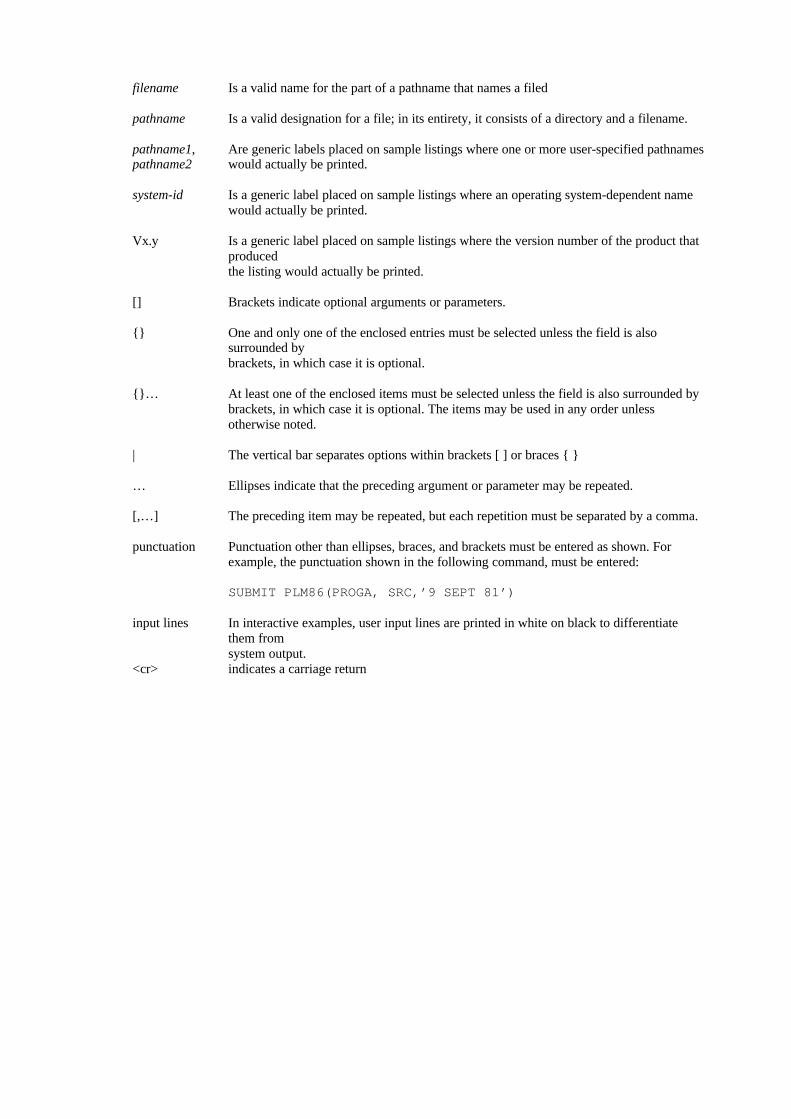
filename Is a valid name for the part of a pathname that names a filed
pathname Is a valid designation for a file; in its entirety, it consists of a directory and a filename.
pathname1, Are generic labels placed on sample listings where one or more user-specified pathnamespathname2 would actually be printed.
system-id Is a generic label placed on sample listings where an operating system-dependent namewould actually be printed.
Vx.y Is a generic label placed on sample listings where the version number of the product thatproducedthe listing would actually be printed.
[] Brackets indicate optional arguments or parameters.
{} One and only one of the enclosed entries must be selected unless the field is alsosurrounded bybrackets, in which case it is optional.
{}… At least one of the enclosed items must be selected unless the field is also surrounded bybrackets, in which case it is optional. The items may be used in any order unlessotherwise noted.
| The vertical bar separates options within brackets [ ] or braces { }
… Ellipses indicate that the preceding argument or parameter may be repeated.
[,…] The preceding item may be repeated, but each repetition must be separated by a comma.
punctuation Punctuation other than ellipses, braces, and brackets must be entered as shown. Forexample, the punctuation shown in the following command, must be entered:
SUBMIT PLM86(PROGA, SRC,’9 SEPT 81’)
input lines In interactive examples, user input lines are printed in white on black to differentiatethem fromsystem output.
<cr> indicates a carriage return

ContentsChapter 1OverviewProduct DefinitionThe PL/M-51 Language
Using a High-Level LanguageWhy PL/M-51 ?
Two Categories of PL/M-51 StatementsBlock Structure
Block Nesting and Scope of Variables: An IntroductionExecutable Statements
Assignment StatementIF StatementDO and END Statements
Built-In ProceduresExpressionsThe Program Development Process
Chapter 2Basics of a PL/M-51 ProgramPL/M-51 Character SetIdentifiers and Reserved WordsTokens, Separators, and the Use of BlanksConstants
Whole Number ConstantsCharacter Strings
Comments
Chapter 3DeclarationsVariable Declaration StatementsTypes
Examples ResultsAddress-Spaces and the Suffix The CONSTANT Suffix The Implicit Dimension Specifier The REGISTER Suffix The IDATA Suffix The MAIN Suffix The AUXILIARY SuffixCompilation Constants (Text Substitution): The Use of LITERALLY

Declarations of Names for LabelsResults
Combining DECLARE StatementsDeclarations for Procedures
Chapter 4Data Types and Based VariablesBYTE and WORD ArithmeticThe Dot (.) OperatorStoring Strings and Constants via Location ReferenceBased VariablesLocation References and Based Variables Cautions on Using Based VariablesContiguity of StorageThe AT Attribute 4
Chapter 5Expressions and AssignmentsOperands Variable References Constants Function and Location References Subexpressions Compound OperandsOperand and Expression TypesArithmetic Operators The +, -, *, and / Operators The MOD OperatorRelational OperatorsLogical OperatorsExpression Evaluation Precedence of Operators: Analyzing an Expression Notes on Relational Operators Order of Evaluation of OperandsAssignment Statements Implicit Type Conversions Multiple AssignmentSpecial Case: Constant Expression Negative Numbers

Chapter 6Structures and ArraysArrays and Subscripted Variables Structures Arrays of Structures Arrays within Structures Arrays of Structures with Arrays inside the StructuresReferences to Arrays and Structures Fully Qualified Variable References Unqualified and Partially Qualified Variable References
Chapter 7Flow Control StatementsDO and END Statements :DO blocks Simple DO Blocks DO CASE Block DO WHILE Blocks Iterative DO BlocksThe IF Statement Nested IF Statements Sequential IF StatementsGOTO StatementsThe CALL and RETURN StatementsThe Null Statement
Chapter 8Sample Program 1Insertion Sort Algorithm
Chapter 9Block Structure, Scope, and Lifetime RulesScopeNames Recognized within BlocksRestrictions on Multiple DeclarationsLifetime RulesExtended Scope: The PUBLIC and EXTERNAL AttributesScope of Labels and Restrictions on GOTOs
Chapter 10Procedures and InterruptsProcedure Declarations Parameters

Typed versus Untyped ProceduresActivating a Procedure: Function References and CALL Statements Indirect Procedure ActivationExit from a Procedure: The RETURN StatementThe Procedure BodyThe Attributes: PUBLIC and EXTERNAL, INTERRUPT, USING, INDIRECTLYCALLABLE Interrupts and the INTERRUPT Attribute: ENABLE and DISABLE The USING Attribute The INDIRECTLY_CALLABLE Attribute
Chapter 11Built-In ProceduresObtaining Information about Variables The LENGTH Function The LAST Function The SIZE FunctionExplicit Type and Value ConversionsSHIFT and ROTATE Functions Logical-Shift Functions: SHL and SHR Rotation Functions: ROL and RORINPUT and OUTPUTMiscellaneous Built-Ins The TESTCLEAR Procedure The TIME Procedure
Chapter 12Features Involving 8051 Hardware FlagsOptimization and the 8051 Hardware FlagsThe PLUS and MINUS OperatorsCarry-Rotation Built-In FunctionsThe DEC Function
Chapter 13Support Library: PLM5 1 .LIB
Chapter 14Compiler Invocation and ControlsInvoking the PL/M-51 Compiler Examples of Control Lines Examples of ControlsThe Object File Controls

INTVECTOR/NOINTVECTOROPTIMIZEOPTIMIZE(0)OPTIMIZE(1)OPTIMIZE(2)OPTIMIZE(3)OBJECT/NOOBJECTDEBUG/NODEBUGROMREGISTERBANK
Listing Selection and Content ControlsPRINT/NOPRINTLIST/NOLISTCODE/NOCODEXREF/NOXREFSYMBOLS/NOSYMBOLS
Listing Format ControlsPAGING/NOPAGINGPAGELENGTHPAGEWIDTHTITLEEJECT
Program ListingSymbol and Cross-Reference ListingWarnings and Compilation SummarySource Inclusion Controls
INCLUDESAVE/RESTORE
-Conditional Compilation ControlsIF/ELSEIF/ELSE/ENDIFSET/RESET
Chapter 15Object Module SectionsModulesSegmentsLinkage InformationDebug Information
Chapter 16Error MessagesSource PL/M-51 Errors
Fatal Command-Tail and Control ErrorsFatal Input/Output ErrorsFatal Insufficient-Memory ErrorsFatal Compiler Failure ErrorsError Messages
Appendix AGrammar of the PL/M-51 Language
Appendix BProgram Constraints
Appendix CPL/M-51 Reserved Words
Appendix DPredeclared Identifiers
Appendix EDifferences between PL/M-80 and PL/M-51
Appendix FASCII Codes
Appendix GInterfacing PL/M-51 to ASM51
Appendix HRun-Time Interrupt Processing
Appendix IThe Processor Descriptor Files
Appendix JSample Program 2
Appendix KHow to Generate Better Code
Appendix LValid PL/M-51 Statements

Appendix MAssembler Utility Library: UTIL51.LIB
Figures
8051 Memory OrganizationInternal Data Addressing ModesInsertion Sort AlgorithmInclusive Extent of BlocksOuter Level of Block SORTASM51 Code for Interrupt Vector and CPU Status Stacking
Tables
PL/M-51 Special CharactersOperators’ PrecedenceCompiler ControlsControls by CategoriesAddress Space CodesTyped Procedure Values

Overview 1This chapter introduces the PL/M-51 language and explains the process of developing software foryour system using PL/M-51.
1.1 Product Definition
PL/M is a high-level language for programming various families of microprocessors and microcontrollers.It was designed by Intel Corporation to meet the software requirements of computers in a wide variety ofsystems and applications work.
The PL/M-51 compiler is a software tool that translates your PL/M-51 source programs into relocatableobject modules that you can link to other modules coded in PL/M, assembly, or other high-level languages.The compiler provides a listing output, error messages, and a number of compiler controls to aid inprogram development and debugging.
To perform the steps following compilation, use software development utilities RL51 and LIB51. Debugyour programs using the ICE-51 In-Circuit Emulator. For firmware systems, use the Universal PromProgrammer (UPP) with its Universal Prom Mapper (UPM) software to transfer your programs to PROM.
1.2 The PL/M-51 Language
Using a High-Level Language
High-level languages more closely model the human thought process than lower-level languages such asassembly language. High-level languages require one less translation step from concept-to-code than dolower-level languages; consequently, high-level languages are relatively easy to write and can be writtenfaster than low-level languages. High-level language programs also are more likely to be correct becauseless chance exists to introduce error.
Programs in high-level languages are easier to read and understand than those in lower-level languages, andthus are easier to modify. As a result, you can develop high-level language programs in a much shorterperiod of time. Also, they are easier to maintain throughout the life of the product. Thus, high-levellanguages result in lower costs for both development and maintenance of programs.
In addition, programs in high-level languages are easily transferred from one processor to another and arethus considered portable.
If PL/M-51 is your first high-level language, you should know how programming in high-level languagesdiffers from assembly-language programming. When you use a high-level language:
• You do not need to know the instruction set of the processor you are using. However, you do need tounderstand its memory structure.
•You need not be concerned with the details of the target processor, such as register allocation or assigningthe proper number of bytes for each data item—the compiler takes care of these things automatically.

•You use keywords and phrases that resemble English.
•You can combine many operations (including arithmetic and Boolean operations) into expressions: thus,you can perform a whole sequence of operations with just one statement.
•You can use data types and data structures that are closer to your actual problem. For instance, in PL/M-51 you can program in Boolean variables, characters. arrays. and other data structures instead of bits, bytesor words.
Coding programs in high-level languages rather than in assembly languages require a different thoughtprocess. Coding in high-level languages is actually closer to the level of thinking you use when you areplanning your overall system design.
Why PL/M?
Many high-level programming languages are available today. Some have been around far longer thanPL/M. So, once you have decided to use a high-level language. you might ask: How does PL/M differ fromother high-level languages? What advantages does it have? When is it the right language to use?
Following are some of the characteristics of PL/M:• It has a block structure and control constructs that aid- in fact, encourage and• enforce structured programming• It includes facilities for such data structures as structured arrays and pointer-based dynamic
variables.• It is a typed language, that is, the compiler does data type compatibility checking to help you
detect logic errors in your programs at compile time.• Its data structuring facilities and control statements are designed logically. Thus. PL/M is a good
language for expressing algorithms for systems programming.• Its control constructs make program correctness relatively easy to verify.• It is a standard language used on Intel microcomputers; consequently, PL/M programs are portable
across Intel processors.
PL/M was designed for programmers (generally systems programmers) who need access to microprocessorfeatures (such as indirect addressing (BASED) and direct I/O) for optimum use of all system resources.
PL/M differs from older, more established languages like FORTRAN. BASIC, and COBOL in many ways.PL/M has many more features than BASIC and is a more general-purpose language than either FORTRAN(best suited for scientific applications) or COBOL (tailored for business data processing). Additionally,PL/M differs from these other languages in its typing and block structure.
1.3 Two Categories of PL/M-51 Statements
PL/M-51 has two types of statements: declarations and executable statements. A simple example of adeclare statement is:
DECLARE WIDTH BYTE ;
This declare statement introduces the identifier WIDTH and associates it with the contents of one byte (8bits) of memory. You need not know the location of the byte, i.e., its actual address in memory. Simplyrefer to the contents of this byte by using the name WIDTH.

An example of an executable statement is:
CLEARANCE = WIDTH * 2;
This executable statement has two identifiers. CLEARANCE and WIDTH. Both must be declared prior tothis executable statement, which produces machine code to retrieve the WIDTH value from memory, adds2 to it, and stores the sum in the memory location for CLEARANCE.
For most purposes, you, the PL/M-51 programmer, need not think in terms of memory locations.CLEARANCE and WIDTH are variables, and the assignment statement assigns the value of the expressionWIDTH + 2 to the variable CLEARANCE. The compiler automatically generates all the machine codenecessary to retrieve data from the right type of memory, evaluates the expression, and stores the result inthe proper location.A group of statements intended to perform a function, i.e., a subprogram or subroutine, can be given aname by declaring them to be a procedure:
ADDER_UPPER: PROCEDURE (BETA);
The statements that define the procedure then follow. This block of PL/M-51 statements is invoked fromother points in the program, which may involve passing parameters to it and returning a value. When aprocedure has finished executing, control is returned immediately to the position following the point atwhich the procedure was called. This capability is the major feature permitting modular programconstruction.
1.4 Block Structure
PL/M-51 is a block-structured language. That is, every statement in a PL/M-51 program is part of at leastone block. (A block is a group of statements that begins with a DO statement or a procedure declarationand ends with an END statement.) -The compilation unit in PL/M-51 is a module, which is a labeled simpleDO-block: therefore, a module must begin with a labeled DO statement and end with an END statement.Between those end points (within that DO-block) other statements provide the definitions of data andprocesses that make up the program. These other statements are part of the block, contained within theblock, or nested within the block. A module can contain other blocks but is never itself contained withinanother block.
(The DO-block is described as simple because it is just one of four DO-blocks: the other three areexplained later in this manual.)
Every PL/M-51 program consists of one or more modules, separately compiled, each consisting of one ormore blocks. PL/M-51 has two kinds of blocks: DO-blocks and procedure definition blocks.
A procedure definition block is a set of statements beginning with a procedure declaration (as shown insection 1.3) and ending with an END statement. Other declarations and executable statements, which cango between these endpoints, are used later when the procedure is actually invoked or called into execution.
A definition block is really a further declaration of everything the procedure will use and do. Since it isonly executed later, a procedure definition block is considered just another form of declaration; it is notregarded as immediately executable.

Block Nesting and Scope of Variables: An Introduction
Some blocks contain entire other blocks, as shown in the following examples.
Example 1
Start: DO;DECLARE (A,B,C,D,E,F,G,H,L) BYTE;A = 17;C = B * D;
middle : DO;DECLARE (J,K) Byte;E = F + G;H = J + K + A;
END middle;
Last: L = H + C;
END start ;
Example 2
Start: DO;DECLARE (A,B,C,D,E,F,G,L) BYTE;A = 17;C = B * D;
Middle : DO;DECLARE (H,J,K,L) Byte;E = F + G;H = J + K + A;
END middle;
Last: L = H + C; /* This is an error since H isundeclared at outer level */
END start ;
(As shown in examples 1 and 2, multiple names of the same type can be declared in one statement;consequently, all the names within the parentheses are of the same type.)
The block called MIDDLE is completely contained inside the block labeled START; MIDDLE is said to benested within the START block.
The START block is called an outer block. The phrase outer level is used to refer to statements that are inSTART but not in MIDDLE. For example, the statements beginning with A = , C = , and B = are all in atthe outer level in the blocks shown in examples 1 and 2.
PL/M-51 permits each block to be independent of other blocks in that any names declared at an outer levelcan be redeclared, with new meanings and values, inside a nested block. If names declared at an Outer levelare not redeclared, they keep their original locations and present contents.

Thus, A will still be 17 inside MIDDLE unless you add a new declaration to make it have a new, localmeaning there. Variables declared inside a nested block have only that local meaning while statements inthat block are being executed. The variables lose their local meaning as soon as execution passes tostatements outside that block.
Therefore, if H is only declared inside MIDDLE, as it is in Example 2, its value will be unknown in thestatement labeled “last:” the statement will be invalid and the compiler will say so. If H is also declared inSTART, the value used in last will be the outer level meaning, unrelated to the one created in MIDDLEbecause that H is unique. They will only be the same if their sole declaration is in START and not inMIDDLE, as in Example 1.
The effect of these rules is that, when writing a block and declaring objects solely for use inside that block,you need not worry about whether the same identifier has already been used in another block. Even if thesame name is used elsewhere, it refers to a different object. This subject is dealt with in detail in Chapter 9.
The notion of nested blocks, inner and outer levels, is central to successful PL/M-51 programming. Forexample, the modules of a program must conform to the rule that only one module may have executablestatements at the outer-most level. That module is called the main module (or sometimes, the mainprogram). The Outer-most level of all other modules must only contain procedure definition blocks andother declarations, as discussed in the sections that follow.
Most of the rules discussed in this book, including those just covered, relate to creating and preservingunambiguous meanings, addresses, and values for each name you use. This uniqueness must be true inevery block and in communicating values between blocks.
1.5 Executable Statements
The following is a list of all PL/M-51 executable statements and the chapters in which they are discussed:
Assignment Statement Chapter 5GOTO Statement Chapter 7IF Statement Chapter 7Simple DO Statement Chapter 7Iterative DO Statement Chapter7DO WHILE Statement Chapter 7DO CASE Statement Chapter 7END Statement Chapter 7Null Statement Chapter 7CALL Statement Chapter 10RETURN Statement Chapter 10ENABLE and DISABLE Chapter 10
The following sections, which give simple descriptions of some of the executable statements, should helpmake you more familiar with PL/M-51 and should aid you when you encounter the full descriptions foundin later chapters.
Assignment Statement
The assignment statement has already been introduced. It is fundamental to PL/M-51 programming.Although its form is quite simple, the expression in an assignment statement may be quite complex andresult in a considerable amount of computation, as will be seen in Chapter 5

The simplest form of the assignment statement is:
Identifier = expression;
Where
Identifier is the name of a variable.
The expression is evaluated, and the resulting value becomes the value of the variable. Variations of thisform are given in Chapter 5.
IF Statement
The following is an example of an IF statement:
IF WEIGHT < MINWT THENCOUNT = COUNT + 1;
ELSECOUNT = 0;
This has been broken into four indented lines to make it more readable. As will be explained in Chapter 2,blanks (spaces, tabs, carriage returns, comments and line feeds) may be freely inserted between theelements of a statement without changing the meaning.
WEIGHT, MINWT, and COUNT are assumed to be previously declared variables. The IF statementexample has three parts:
• An IF part, consisting of the reserved word IF and a condition. WEIGHT < MINWT• A THEN part, consisting of the reserved word THEN and a statement. COUNT = COUNT + 1• An ELSE part, consisting of the reserved word ELSE and another statement, COUNT = 0
If the condition in the IF part of an IF statement is “true,” then the statement in the THEN part” will beexecuted. Otherwise, the statement in the ELSE part will be executed.
In the example given, if the value of WEIGHT is less than the value of MINWT, then the value of COUNTwill be incremented by 1. Otherwise, the value 0 will be assigned to COUNT.
The ELSE part of an IF statement is optional. Chapter 7 contains a full description of IF statements.
DO and END Statements
DO and END statements are used to construct DO blocks. A DO block begins with a DO statement andends with a matching END statement.
PL/M-51 has four kinds of DO statements, which are used to construct four kinds of DO blocks.

A simple DO block begins with a simple DO statement and (like all DO blocks) may be used wherever asingle statement can be used. The following is an example of a simple DO block used in place of a singlestatement in the THEN part of an IF - -statement:
IF TMP > = 4 THEN DO;INCR = INCR + 2;COUNT = COUNT + INCR;END;
ELSECOUNT = 0;
This example allows two or more executable statements to be executed if the condition is true.
An iterative DO statement introduces an iterative DO block and causes the executable statements within theblock to be executed repeatedly. The following is an example of an iterative DO statement
DO J = 0 TO 9;VECTOR(J) = 0;
END;
where
J is a previously declared BYTE or WORD variable (which are discussed in detailin Chapters 3, 4.and 5).
VECTOR Must be a previously declared array having at least 10 elements.
The assignment statement is executed 10 times, with values of J starting at 0 and increasing by 1 each timearound until all of the integers 0-9 have been used. Since J is used as a subscript for specifying whichelement of VECTOR is referenced in the assignment statement, this iterative DO block assigns the value 0to all elements of VECTOR from element 0 through element 9.
The DO WHILE statement contains a condition (like the condition in the IF part of an IF statement), andcauses the executable statements in the block to be executed repeatedly as long as the condition is true.
In the following example. a DO WHILE block is used to step through the elements of an array (TABLE)until an element is found that is greater than the value of a scalar variable called LEVEL.
I = 0;DO WHILE TABLE(I) < = LEVEL;
I = I + 1;END;
TABLE is a previously declared array, and LEVEL and I are previously declared variables. I is firstassigned a value of 0, then is used as a subscript for TABLE. Because I is incremented in each execution ofthe DO WHILE block, a different element of TABLE is compared with LEVEL each time the DO WHILEstatement is executed. When an element is found that is greater than LEVEL, the condition in the DOWHILE statement is no longer true, the block is not repeated again, and control passes to the next statementafter the END statement. At this point, the value of I is the subscript of the first element of TABLE that wasnot greater than LEVEL.

The DO CASE block, which is introduced by a DO CASE statement, uses the value of the givenexpression. to select a statement to be executed. In the following example, assume that the expression TST-l in the DO CASE statement can have any value from 0 to 3.
DO CASE TST-1;RED = 0;BLUE = 0;GREEN = 0;GREY = 0;
END;
If the value of the expression is 0, only the first assignment statement will be executed, and the value 0 willbe assigned to RED. If the value of the expression is 1, only the second assignment statement will beexecuted, and the value 0 will be assigned to BLUE. Expression values of 2 or 3 will cause GREEN orGREY, respectively, to be assigned the value 0.
1.6 Built-In Procedures
PL/M-51 has many built-in procedures. These procedures provide such functions as shifts and rotations,data type conversions, and test-and-set. The built-in procedures are described in Chapter 11.
1.7 Expressions
As already noted, a PL/M-51 expression is made up of operands and operators, and resembles aconventional algebraic expression.
Operands include numeric constants (such as 378 or 105) and variables (as well as other operands,discussed in Chapters 4 and 5). The operators include + and - for addition and subtraction, * and / formultiplication and division, and MOD for modulo arithmetic.
As in an algebraic expression, elements of a PL/M-51 expression may be grouped with parentheses.
1.8 The Program Development Process
The PL/M-51 compiler and run-time libraries are part of an integrated set of tools that make up the totalMCS-51 development solution for your microcomputer system.
The steps in the software development processes are as follows:
1. Define the problem completely.
2. Outline the proposed solution in terms of hardware plus software. Once this step is done, you maybegin designing your hardware.
3. Design the software for your system. This important step consists of several sub steps, includingbreaking down the task into modules, choosing the programming language, and selecting thealgorithms to be used.

4. Code your programs and prepare them for translation using a text editor.
5. Translate your PL/M program code using the PL/M-51 compiler.
6. Using the text editor, correct any compile-time errors; then, recompile.
7. Link the resulting relocatable object modules with PLM51.LIB and locate your.object code usingRLSI for both purposes.
8. Test the resulting program using ICE-S 1 or other tools, and repeat steps 6 through 8 until theprogram performs correctly.

Basics of a PL/M-51 Program 2PL/M-51 programs are written free-form, which means it is insignificant where a statement is placed on aninput line, and blanks can be freely inserted between the elements of the program.
2.1 PL/M-51 Character Set
The character set used in PL/M-51 is a subset of the ASCII character set, as follows:
ABCDEFGHIJKLMNOPQRSTUVWXYZabcdefghijklmnopqrstuvwxyz0123456789
along with the special characters
= . / ( ) + - ‘ * , : ; $ _ < >
and the blank or space, plus the tab, carriage-return, and line-feed characters.
The rules in this section apply to everything in a PL/M-51 program except character string constants, whichare discussed in section 2.4, and comments, which are discussed in section 2.5.
If a PL/M-51 program contains any character not in the set above, the compiler treats it as an error.
Uppercase and lowercase letters are not distinguished from each other except in string constants. Forexample, xyz and XYZ are interchangeable. In this manual, all PL/M-51 code is in uppercase letters to helpdistinguish it from explanatory text.
Blanks are not distinguished from each other except in string constants. The compiler treats any unbrokensequence of blanks as a single blank.
Special characters and combinations of them have particular meanings in a PL/M-51 program, as describedin the remainder of this manual.
Table 2-1 presents a glossary of special characters and combinations.
2.2 Identifiers and Reserved Words
Identifiers are used to name variables, procedures, symbolic constants, and statement labels. Identifiers maybe up to 31 characters in length. The first character must be alphabetic, and the remainder may be eitheralphabetic, numeric, or the underscore (_) or dollar sign ($).
Embedded dollar signs are totally ignored by the compiler, and may be used freely to improve thereadability of an identifier or constant (although the $ may not be the first character). An identifier orconstant containing a dollar sign is exactly equivalent to the same identifier with the dollar sign deleted.

Table 2-I. PL/M-51 Special Characters
Symbol Name Use= equal sign Two distinct uses:
(1) assignment operator(2) relational test operator
. dot Two distinct uses:(1) structure member qualification(2) address operator
//**/
slash division operatorbeginning-of-comment delimiterend-of-comment delimiter
( left paren left delimiter of lists, subscripts and some expressions) right paren right delimiter of lists, subscripts, and some expressions+ plus addition operator or unary plus operator- minus subtraction or unary minus operator‘ apostrophe string delimiter* Asterisk multiplication operator, implicit dimension specifier< less than relational test operator> greater than relational test operator
< = less or equal relational test operator> = greater or equal relational test operator<> not equal relational test operator: Colon label delimiter; Semicolon statement delimiter, comma list-element delimiter_ Underscore significant character in identifier$ Dollar non-significant character in identifier
Examples of valid identifiers are:
INPUT_COUNTXGAMMLONGIDENTIFIERNUMBER3LONG$$$IDENTIFIER$$$NUMBER$$$3INPUT$COUNTINPUTCOUNT
The two long identifiers are identical (as viewed by the compiler). The last two examples areinterchangeable, but different from the first.
Certain reserved words must not be used as identifiers because they are actually part of the PL/M-51language. These are listed in Appendix C.
PL/M-51 also has a set of predeclared identifiers naming built-in procedures. You are permitted to declarethese names for your own purposes, but, when you do so, the built-in procedure with the same namebecomes inaccessible. Appendix D lists these identifiers.

2.3 Tokens, Separators, and the Use of Blanks
Just as an English sentence is made up of words, so a PL/M-51 statement is made up of tokens. Every tokenbelongs to one of the following classes:
• Identifiers• Reserved words• Simple delimiters (all of the special characters, except the underscore and dollar sign, are simple
delimiters)• Compound delimiters—the following combinations of two special characters:
<> < = > = /* */• Numeric constants (discussed in section 2.4)• Character string constants (discussed in section 2.4)
For the most part, it is obvious where one token ends and the next one begins. For example, in theassignment statement
EXACT = APPROX * (OFFSET-3) / SCALE;
EXACT, APPROX, OFFSET, and SCALE are identifiers, 3 is a numeric constant, and all the othercharacters are simple delimiters.
Sometimes a simple or compound delimiter does not occur between two identifiers, reserved words, ornumeric constants, e.g., DECLAREABYTE. In these cases, a blank must be placed between them as aseparator, i.e., DECLARE A BYTE. (Instead of a single blank, any unbroken sequence of blank charactersmay be used.)
Also, a comment (see section 2.5) may be used as a separator.
Blanks may also be inserted freely around any token, without changing the meaning of the PL/M-51statement. Thus, the assignment statement
EXACT = APPROX * ( OFFSET - 3 ) / SCALE;
is equivalent to
EXACT = APPROX * (OFFSET-3) / SCALE;
2.4 Constants
A constant is a value that does not change during your program’s execution. An explanation of constantsfollows.
Whole Number Constants
Whole-number constants can be binary, octal, decimal, or hexadecimal. The compiler recognizes these by asuffix of B, 0 (or Q), D, or H, respectively. Numbers without a suffix are considered decimal. If a constantcontains characters invalid in the designated number base, it will be flagged as an error.
For example, the maximum whole-number word constant is:
1111$1111$1111$1111B = 177777Q = 65535D = 0FFFFH

The first character of a hexadecimal number must be a numeric digit to avoid looking like an identifier. Forexample, the hexadecimal representation for 163 must be written 0A3H rather than A3H, which would bemistaken for an identifier.
Following are examples of valid whole-number constants:
12AH 2 330 1010B 55D 0BF3H 65535 777D 3EACH
Following are examples of invalid whole-number constants:
• 12A hexadecimal digits used without an H suffix, hence invalid in the default decimalinterpretation.
• I2AD the final D could be a suffix; however, the A is not a decimal digit. If hexadecimal isintended, a final H is needed.
• 102B 2 is not a valid binary digit.• 2ADGH—G is not a valid hexadecimal digit.
A whole-number constant can be a BIT, BYTE or WORD value, depending on its size and context.
Character Strings
Character strings are denoted by printable ASCII characters enclosed within apostrophes. To include anapostrophe in a string, write it as two apostrophes; e.g., the string ‘’’Q’ consists of 2 characters, anapostrophe followed by a Q. Spaces are allowed. The compiler represents character strings in memory asASCII codes, one 7-bit character code to each 8-bit byte, with a high-order zero bit. Strings of length 1translate to single-byte values; strings of length 2 translate to double-byte values. Following are examples ofcharacter strings.
‘A’ is equivalent to 41 H
‘AG’ is equivalent to 4147H
(See ASCII code table in Appendix F.)
Therefore, character strings can only be used as BYTE or WORD values because strings longer than 2characters would exceed the 16-bit capacity of a WORD value. As constants, however, longer characterstrings are stored as a sequence of bytes and can be used in a PL/M-51 program (see sections 3.1, 3.2 and3.3).
The maximum length of a string constant is 254 characters. A string constant may be used for initialization,or as part of a location reference pointing to where that string constant is stored.
2.5 Comments
Explanatory comments may be interleaved with PL/M-51 program text to improve readability and provideprogram documentation. A PL/M-51 comment is a sequence of characters delimited on the left by thecharacter pair /* and on the right by the character pair */ . These delimiters instruct the compiler to ignoreany text between them, and to consider such text not part of the program proper.
A comment may contain any printable ASCII character and may also include space, carriage-return, line-feed, and tab characters.

A comment may not be embedded inside a character string constant because it will become part of the stringand the compiler won’t recognize it. Apart from this, it may appear anywhere that a blank character mayappear—that is, anywhere except embedded within a token. Thus, comments may be freely distributedthroughout a PL/M-51 program.
The following is a sample PL/M-51 comment:
/* This procedure copies one structure to another. */
In this manual, comments are presented in mixed uppercase and lowercase to help distinguish them visuallyfrom program code, which is always presented in uppercase.

Declarations 3Five types of objects can be declared to have symbolic names: variables, constants, LITERALLYs, labels,and procedures. Exactly one declaration must be available for each name used in a block - no more, no less.This declaration may appear at the beginning of the block, or in an outer block. Multiple declarations of thesame name in the same block are invalid.
Variables, constants, LITERALLYs and procedures must be declared before they can be used in executablestatements. Labels may be declared or implicitly declared by appearing before a colon. A procedure isdefined by the statements between the PROCEDURE statement and the final END of the procedure.
In addition to the item’s name, a declaration describes its type, attributes, and / or location. These termswill be clarified in the course of this chapter.
3.1 Variable Declaration Statements
A DECLARE statement is a non-executable statement that introduces some object or collection of objects,associates names (and sometimes values) with them and allocates storage, if necessary. The most importantuse of DECLARE is for declaring variables.
A variable may be scalar—that is, a single quantity—or an array, or a structure.
A scalar variable is a single object whose value is not necessarily known at compile time and may changeduring the execution of the program. You therefore refer to it by declaring a name to be used in theprogram: an identifier.
The term variable has a more general meaning: a variable may be a scalar variable, or it may be a list ofscalars referred to by a single identifier.
An array is a list of scalars all named by the same identifier, differentiated from each other by the use ofsubscripts, e.g., A(0), A(1), A( 123), etc.
A structure is a list of scalars and / or arrays which all use the same main identifier and which can bedifferentiated from each other by their own member-identifiers (field names). For example,EMPLOYEES.NAME could refer to the NAME field within the structure EMPLOYEES. Variables of thiskind, known as arrays and structures, are discussed in greater detail in Chapter 6.
Examples of the use of scalars, scalar variables, and arrays follow the introduction to section 3.2.
3.2 Types
A scalar always has a type: BYTE, WORD, or BIT.• A BYTE scalar is an 8-bit quantity occupying one byte of memory . The value of a BYTE scalar is
an unsigned whole number that ranges from 0 to 255.• A WORD scalar is a 16-bit quantity occupying two contiguous bytes of memory, with its most
significant 8 bits stored in the first byte (lower address). The value of a WORD scalar is anunsigned whole number that ranges from 0 to 65535. For compatibility with other PL/Mcompilers, the keyword ADDRESS can be used synonymously with WORD.

• A BIT scalar is one bit having a value of either 0 (false) or 1 (true). Bits must reside in the bit-addressable locations of the on-chip RAM (MAIN addresses 32 through 47), or in a memory-mapped hardware register that is bit-addressable (see Chapter 2 of the MCS-51 Family of SingleChip Microcomputer User’s Manual). Thus, bits may only have a suffix of MAIN or REGISTER(see the discussion of suffixes which follows later in this section).
BITs have several important restrictions:
• Bits cannot be subscripted; i.e., BIT arrays do not exist.• Bits cannot be BASED (Chapter 4 explains BASED variables).• Bits residing in MAIN cannot be AT. Bits mapped to hardware registers must be AT the correct
register address.• Bits can be structure members. However, a structure that contains BIT members may not contain
non-bit members, may not be an array member, and may not be BASED (it may be AT, if it is aspecial function register bit.) Note that bit structures can be overlaid by bytes to allow access ofmemory locations by either BIT or BYTE statements. For example,
DECLARE S1 STRUCTURE ((B0, B1, B2, B3, B4, B5, B6, B7) BIT);DECLARE SI_OVER BYTE AT (.S1);
• A maximum of 64 bits is allowed.• A PUBLIC BIT cannot be declared AT REGISTER; the following example is illegal:
DECLARE OLD BIT PUBLIC AT (99H) REGISTER
The BITs restrictions are not arbitrary; they stem from the MCS-51 architecture and therefore cannot becircumvented using ASM51.
The concept of data types applies not only to variables but to every value processed by a PL/M-51 program.This includes values returned by procedures and values calculated by processing expressions.
Arithmetic and other expressions using the different types are discussed in detail in Chapter 5.
Examples
The following statements declare scalars:
DECLARE APPROX WORD;DECLARE (OLD, NEW) BIT;DECLARE POINT WORD, VAL12 BYTE;
The first example declares a single scalar variable of type WORD, with the identifier (name) APPROX.
The second example declares two scalars, OLD and NEW, both of type BIT. This kind of statement iscalled a “factored declaration.” It is equivalent to the following sequence:
DECLARE OLD BIT;DECLARE NEW BIT;
except the factored declaration guarantees that the bits will be contiguous.
The third example declares two scalars of different types: POINT is of type WORD, and VAL12 is of typeBYTE.

The following statements declare arrays:
DECLARE DOMAIN (12) BYTE AUXILIARY;DECLARE GAMMA (19) WORD;
The first statement declares the off-chip RAM array DOMAIN (AUXILIARY is explained in thediscussion of suffix later in this section),. with 12 scalar elements, each of type BYTE. These elements aredistinguishable by subscripting the name DOMAIN, using the range 0 to 11 for the subscripts. Forexample, the third element of DOMAIN can be referred to as DOMAIN(2). The first element of every arrayhas subscript 0.
The second statement declares the array GAMMA, with 19 scalar elements of type WORD. The subscriptsfor this array can range from 0 to 18.
The next statement declares a structure with two scalar members:
DECLARE RECORD STRUCTURE (KEY BYTE, INFO WORD);
The two members are a BYTE scalar that can be referred to as RECORD.KEY and a WORD scalar thatcan be referred to as RECORD.INFO. The word named by RECORD.INFO is the second and third bytes ofthis structure.
Structures and arrays are discussed further in Chapter 6.
Results
The two results of a valid variable declaration are:
1. The name is given an address and an address space.2. It is considered to have the attributes declared.
The two results mean all subsequent uses of the variable in this block will refer to the same address (exceptfor based variables, discussed in section 4.4).
The results also require all references to the variable to conform to the rules for the current attributes, i.e.,those having priority in the current block. Requiring all references to the variable to conform to the rulesfor the current attributes allows the compiler to flag a large variety of errors of inconsistency, i.e.,incompatibility of declarations with later usage (at this level of the block).
3.3 Address-Spaces and the Suffix
Figure 3-1 shows the 8051’s memory. Note the 4 memory spaces: program memory (called CONSTANT inPL/M-51), internal data RAM (called MAIN or IDATA), the special function registers (calledREGISTER), and external data memory (calledAUXILIARY).
Figure 3-2 shows the internal data memory in more detail.
If you understand figures 3-1 and 3-2, you know enough about the MCS-51 family to proceed. Everythingin this family is some flavor of memory; this includes I / O, which is done using the REGISTER address-space (memory-mapped I / O). For example, on the 8051, the program fragment:
DECLARE SBUF BYTE AT(99H) REGISTER;DECLARE X BYTE;X SBUF

EXTERNALOverlapped Space
ProgramMemory
InternalData Ram
SpecialFunctionRegister
ExternalData
Memory
0
4096
64K
0
128
256
0
64K
128
256INTERNAL
Internal Data Memory
Figure 3-1. 8051 Memory Organization
128
Addressablebits in SFR’s128 bits
F8HF0HE8HE0HD8HD0HC8HC0HB8HB0HA8HA0H98H90H88H80H
Internal Data RAMSpecialFunctionRegister
255
255
128 135 128
255 248
127
127 120
7 0
REGISTERS
ADDRESSABLEBYTE IN RAM(128 bits)
Internal DATA RAM Special Function Register
R7 Bank 0R0
32
R7 Bank 1R0
R7 Bank 2R0
R7 Bank 3R0
24
16
8
0
48
Figure 3-2. Internal Data Addressing Modes
will read (into the variable X) a character from the serial port because SBUF (see figures 3-2 and 3-3 of theMCS-SI Family of Single Chip Microcomputer User’s Manual) is the device-register containing serial-portdata. Similarly,
DECLARE BIT2_OF_PORT_2 BIT AT(0A2H)BIT_ 2 OF_PORT_2 = NOT BIT_2_OF_PORT_2;
will flip bit 2 of I / O port 2. (To see why the program fragment flips bit 2 of I / O port 2, refer to figure -3-4 of the MCS-SI Family of Single Chip Microcomputers User’s Manual.)

A variable in most programming languages has a name and a type (i.e., COMPLEX, INTEGER, RECORD,...). A PL/M-51 variable has a name, a type, and an address-space. As just seen in the last few paragraphs,getting the address-space wrong will cause you to write an incorrect program.
Since the 8051 has more than one memory-space, an address by itself is not enough to specify in PL/M-5 1where a variable resides; you must declare the memory in which it resides. Declaring the memory in whicha variable resides is done using the suffix part of the declaration. The suffix can be any of the following:
MAIN - refers to the directly-addressable on-chip RAM.AUXILIARY - refers to the off-chip RAM.REGISTER - refers to (memory-mapped) hardware registers.IDATA - refers to indirectly-addressable on-chip RAM.CONSTANT - i.e., ROM.
If you do not specify a suffix, MAIN is assumed. If the suffix is IDATA, the variable resides within theindirectly-addressable on-chip memory (bytes 0-127 for the 8051; bytes 0-191 for the 8044). If REGISTERis specified, it must be preceded by an AT attribute; the address in the AT attribute must be between 128and 255 (inclusive) and the variable must be of type BIT or BYTE.
The CONSTANT Suffix
The CONSTANT suffix declares variables in the CONSTANT memory-space, which must be ROM. Thecontent of a constant variable, as opposed to other variables, is not altered and remains constant throughoutthe entire program execution.
CONSTANT data initializations can be used in declarations at any block level in the program. The name ofconstant variables should never appear on the left-hand side of an assignment statement.
The PL/M-51 user is allowed to add an initialization to the CONSTANT keyword. You will almost alwaysdo it for non-BASED variables. Initialization is forbidden for BASED or EXTERNAL variables.Initialization may follow the use of the AT attribute discussed in section 4.7; but, if doing so causesmultiple initializations, the result cannot be predicted.
The general form of an initialization is:
CONSTANT (value-list)
Where
value-list is a sequence of values separated by commas.
Values, taken one at a time from the value list, are used to initialize the individual scalars being declared.The initialization is performed in the same manner as an assignment. Initial values for members of an arrayor structure must be specified explicitly.
Each value may be a 1-byte or 2-byte string (e.g., ‘A’, ‘NO’) or a restricted expression, as explained in thenext paragraph. (BYTE arrays can accommodate longer strings because each element can represent onecharacter.)
A restricted expression is one of the following three possibilities:• A location reference formed with the dot operator ( . ), which must refer to a variable that has
already been declared. (Location references are discussed in Chapter 4).

• A constant expression containing no operators except + or - . A constant expression only haswhole number constants as operands, e.g., 2048- 256 + 5, as explained in Chapter 5. A constantexpression above 2551s illegal for initializing a BYTE.
• A location reference plus or minus a constant expression.
The following declaration
DECLARE THRESHOLD BYTE CONSTANT(48);
declares the BYTE scalar THRESHOLD in ROM, (i.e. its value may not be altered) and initializes it to avalue of 48.
The following declaration
DECLARE (COUNTER, LIMIT, INCR) WORD CONSTANT(1024,0,-2);
declares the WORD scalars COUNTER, LIMIT, and INCR, indicates they are in ROM, and initializesCOUNTER to a value of 1024, LIMIT to a value of 0, and INCR to a value of —2 (i.e., 65534).
The following declaration
DECLARE EVEN (5) BYTE CONSTANT(2,4,6,8,10);
declares the BYTE ROM array EVEN, and initializes its five scalar elements to 2, 4, 6, 8, and 10,
The following declaration
DECLARE COORD STRUCTURE (HIGH$BOUND WORD,VALUE (3) BYTE,LOWSBOUND BYTE) CONSTANT(302,3,6, 12,0);
declares the structure COORD, causes it to reside in ROM, and initializes it as follows:
COORD.HIGH$BOUND to 302COORD.VALUE(0) to 3COORD.VALUE(1) to 6COORD.VALUE(2) to 12COORD.LOW$BOUND to 0.
If a string appears in the value list, it is taken apart from left to right and the pieces are stored in the scalarsbeing initialized. One character is stored in each BYTE scalar and two in each WORD scalar. For example,
DECLARE GREETING (S) BYTE AT (1600) CONSTANT(’HELLO’)
causes GREETING(0) to be initialized with the ASCII code for H, GREETING(1) with the ASCII code forE, and so forth.
The examples shown thus far have value lists that match up one-for-one with the scalars being declared. Itis permissible for the value list to have fewer elements than are being declared. Thus,
DECLARE DATUM (100) BYTE CONSTANT(3,5,7,8);
is permissible. The first four elements of the array DATUM are initialized with the four elements in thevalue list, and the remainder of the array is left un-initialized. The value list, however, may not have moreelements than are being declared.

The use of location reference is demonstrated in the following example:
DECLARE GO$NO$GO$MSG(5) BYTE CONSTANT (‘NOGO’,0),GOSNOSGO$MSG$PTR(2) WORD CONSTANT (.GOSNOSGO$MSG, .GO$NO$GO$MSG + 2)
The first CONSTANT contains a message; the second CONSTANT consists of two constant pointers—thefirst of which points to the entire message (NOGO), and the second to its suffix only (GO).
The Implicit Dimension Specifier
When initializing an array, you want the array to have the same number of elements as the value list. Thiscan be done conveniently by substituting the implicit dimension specifier for an ordinary dimensionspecifier (a parenthesized constant). The implicit-dimension specifier has the form:
( * )
For example, the following statement:
DECLARE MSG( * ) BYTE CONSTANT(’WELCOME!’);
declares a BYTE array in ROM, MSG, with enough elements to contain the string ‘WELCOME!’ (namely,8). and initializes the array elements with the characters of the string.
The implicit dimension specifier may only be used for arrays having a CONSTANT suffix and aninitialization.
The implicit dimension specifier may be used with any value list—it is not restricted to strings.
The REGISTER Suffix
All interaction between the 8051 CPU and the outside world is done via the hardware-register addressspace, which contains pseudo-variables like SBUF (the serial-port buffer), P1(1 / 0 port I) and SP (the stackpointer). If the 8051, for instance, writes a byte into SBUF, the byte will be output on the serial-channelinterface.
This rule holds also in PL/M-51. To access a hardware register, declare it as a REGISTER (with the correctaddress in the AT part). Then, for example, you can write P2P3 if you want to copy port 3 to port 2. Lookup the user manual for the relevant chip if you want to work out each REGISTER variable’s actions. On the8051, for example, P0 (I / O port 0) is located at 80H. A declaration for this register will look like thefollowing:
DECLARE P0 BYTE AT (80H) REGISTER;
To help you avoid incorrect register declarations, Intel provides file REG51.DCL, with ready-madedeclarations for all registers on the 8051 chip.
NOTE
The compiler uses the ACC, B, PSW, DPL and DPH registers to accomplish various computations and tohold temporary results. Use of these registers in the user program, although permitted, may causeunpredictable results (e.g., PSW = OFFH is dangerous).

The IDATA Suffix
The MCS-5l architecture permits up to 256 bytes of on-chip RAM. Bytes 0— 127 are directly-addressableand indirectly-addressable. Bytes 128—255 (unimplemented in the 8051) are indirectly-addressable only;direct-address accesses to these addresses gets you into REGISTER space.
To use bytes 128—255, you have to use the IDATA suffix in your declarations. Variables with this suffixare guaranteed to be accessed by indirect addressing only, and may therefore reside anywhere in on-chipRAM. Such indirect access is, however, usually less efficient than direct addressing.
The MAIN Suffix
If you do not specify a suffix, a suffix of MAIN is assumed, i.e., directly-addressable on-chip RAM.Variables with this suffix will reside in addresses 0 -127 of on-chip RAM. This is the fastest memoryavailable, but should be used sparingly.
Omitting an explicit suffix can lead to trouble. Examples of this can be found in Chapter 4, section 4.5, in“Cautions on Using Based Variables.”
The AUXILIARY Suffix
It is possible to add up to 65536 bytes of external memory to the 8051. Added memory is a separate addressspace. The suffix needed to declare a variable in this memory-space is AUXILIARY. For example,
DECLARE X WORD PUBLIC AT (2000H) AUXILIARY;
declares X as a WORD variable at location 2000H in added memory. References to variables with theAUXILIARY suffix are slower than MAIN or IDATA variables.
3.4 Compilation Constants (Text Substitution):
The Use of LITERALLY
If your program is large enough to have many declarations, you might want to declare a compilationconstant to save time at the keyboard:
DECLARE DCL LITERALLY ‘DECLARE’;
Thereafter, during compilation, every time DCL appears alone (not as part of a word), the full stringDECLARE will be substituted by the compiler. Subsequent declarations can thus be written:
DCL SWITCH BIT;DCL AREA BYTE;DCL SIZE WORD;
A declaration using the reserved word LITERALLY defines a parameterless macro for expansion atcompile-time. You declare an identifier to represent a character string that will then be substituted for eachoccurrence of the identifier in subsequent text. This expansion will not take place in strings or constants.The form of the declaration is:
DECLARE identifier LITERALLY ‘string’ ;

where
identifier is any valid PL/M-5l identifier.String is a sequence of arbitrary characters from the PL/M-51 set that do not exceed
254 in length.
The following example illustrates another use of LITERALLY:
DECLARE TRUE LITERALLY ‘1’, FALSE LITERALLY ‘0’;
DECLARE ROUGH BIT;DECLARE (X,Y,DELTA, FINAL) WORD;. . .ROUGH = TRUE;
DO WHILE ROUGH;X = SMOOTH (X,Y,DELTA);/* SMOOTH is a procedure declared elsewhere.’ *IF (X-FINAL) < DELTA THEN ROUGH = FALSE;
END;. . .
This LITERALLY declaration example defines the Boolean values TRUE and FALSE in a mannerconsistent with the way PL/M-5l handles relational operators (see section 5.4). This kind of literalsubstitution for fixed values often makes a program more readable.
Another LITERALLY declaration use: the declaration of quantities that are fixed for one compilation butmay change from one compilation to the next. Consider the following example:
DECLARE BUFFER$SIZE LITERALLY ‘32’;DECLARE PRINT$BUFFER(BUFFER$SIZE) WORD;. . .PRINT$BUFFER(BUFFER$SIZE - 10) = ’G’;. . .
A future change to BUFFER$SIZE can be made in one place, at the first declaration, and the compiler willpropagate it throughout the program during compilation. Thus, the programmer is saved the tedious and.error-prone process of searching the program for the occurrences of “32” that are buffer size referencesand not some other reference.
3.5 Declarations of Names for Labels
A label marks the location of an instruction as opposed to a data item. Labels are permitted only on anexecutable statement, not on declarations.
A name may be declared a label either explicitly or implicitly. The explicit label declaration is used mainlyto allow module-to-module references, which are discussed in detail in Chapter 9. The three possible formsfor explicit label declarations look like this;
DECLARE PART3 LABEL;DECLARE START1 LABEL PUBLIC; /* for inter module reference */DECLARE PHASE2 LABEL EXTERNAL; /* for inter module reference */
The rules for the PUBLIC and EXTERNAL label declarations are discussed in Chapter 9.

The more common implicit label declaration is simpler than the explicit label declaration: the name isplaced at the very beginning of the executable statement to which it is supposed to point:
START2: ALPHA * 127;L1: L2: L3: L4: ; /* four labels on an empty statement */
This label declaration statement defines the label START2 as pointing to the location of the PL/M-51instruction shown. If this block has no explicit declaration of START2, i.e., no statement like:
DECLARE START2 LABEL;
then the compiler considers the definition in the label declaration an implicit declaration and a definition -as if the declaration had occurred at the start of the inner most simple DO or procedure block in which thelabel is contained. (If an explicit declaration is present, the actual placement of the label remains simply adefinition.)
Labels are used to indicate significant instructions or the starting point of instruction sequences. They canbe useful reference points for understanding the parts of a program; they are also useful as targets for thetransfer of control during execution (as discussed under GOTO in Chapter 7).
Results
The results of a valid label declaration are:
1. The declared name can be used to point to an executable instruction.2. The use of a declared name as a variable in the block in which it is declared is disallowed.3. If the label defined in this block appears on an executable statement, the address of that statement isassigned as the value of the label.
3.6 Combining DECLARE Statements
A separate DECLARE statement is not required for each and every declaration. Instead of writing the twoDECLARE statements:
DECLARE CHR BYTE CONSTANT (‘A’);DECLARE COUNT WORD;
you may write both declarations in a single DECLARE statement, as follows:
DECLARE CHR BYTE CONSTANT (‘A’), COUNT WORD;
This DECLARE statement contains two declaration elements, separated by the comma. Every DECLAREstatement contains at least one declaration element. If it contains more than one, they are separated bycommas.
Most of the examples shown up to this point have only one declaration element in each DECLAREstatement. A declaration element is the text for declaring one identifier (or one factored list of identifiers).In the example just cited, the text CHR BYTE CONSTANT(’A’) is one declaration element, and the textCOUNT WORD is another.

Another way of combining declaration elements is called a factored declaration. For example,
DECLARE A BYTE, B BYTE;DECLARE C WORD, D WORD;DECLARE E BYTE, F BYTE;
can be combined as:
DECLARE (A,B) BYTE,(C,D) WORD, (E,F) BYTE;
In each Factored declaration, the allocated locations will be contiguous.
The declaration elements appearing in a single DECLARE statement are completely independent of eachother, as if they were declared in separate DECLARE statements.
3.7 Declarations for Procedures
As already shown, the declaration of a procedure begins by giving its name, with a statement of the form:
name: PROCEDURE
followed optionally by parameters, type, and / or attributes. The definition of the procedure then follows,i.e., the set of statements declaring items used in the procedure (including any parameters) and theexecutable statements of the procedure itself. The definition ends with an END statement, optionallyincluding the procedure name from the declaration.
The complete declaration of a procedure includes all of the statements from the PROCEDURE statementsthrough the END statement. This whole definition / declaration must appear before the procedure name isused in an executable statement, just as variable and constant names must be declared before their use.
The only exceptions occur when the full definition appears in another module where it is declared PUBLIC.If a separate module intends to make use of that public definition, the using module is required to:
1. Declare the procedure as having the attribute EXTERNAL (so RL51 will search for it).
2. Declare each formal parameter the procedure uses, thereby allowing the compiler to verify correctusage when the current module calls the procedure.
3. End the local declaration with an END statement, as follows:
SUMMER: PROCEDURE (A,B) EXTERNAL;DECLARE A WORD, B BYTE;END SUMMER;
The full details of intermodule referencing are in Chapter 9. The discussion of procedure definition andusage is in Chapter 10.

Data Types and Based Variables 44.1 BYTE and WORD Arithmetic
The value of a BYTE variable is an 8-bit binary number ranging from 0 to 255 and occupying one byte ofmemory. The value of a WORD variable is a 16-bit binary number ranging from 0 to 65535 and occupyingtwo contiguous bytes of memory. Values of WORD and BYTE variables are treated as unsigned binaryintegers.
Unsigned integer arithmetic is used in performing any arithmetic operation upon WORD and BYTEvariables. All of the PL/M-51 operators may be used with them (see Chapter 5). Arithmetic and logicaloperations on such variables yield a result of type BYTE or WORD, depending on the operation and theoperands. Relational operations always yield a true or false result of type BIT.
With unsigned arithmetic, if a large value is subtracted from a smaller one, the result is the two’scomplement of the absolute difference between the two values. For example, if a BYTE value of 1(00000001 binary) is subtracted from a BYTE value of 0 (00000000 binary), the result is a BYTE value of255 (11111111 binary).
Also, the result of a division operation is always truncated (rounded down) to a whole number. Forexample, if a WORD value of 7 (0000000000000111 binary) is divided by a BYTE value of 2 (00000010binary), the result is a word value of 3 (0000000000000011 binary).
4.2 The Dot (.) Operator
A location reference is formed by using the ‘.“ operator. A location reference has a value of type WORD—that is, a location address.The basic form of a location reference is:
.variable-ref
wherevariable-ref is the name of some non-BIT variable.
The value of this location reference is the actual location at run time of the variable.
variable-ref may also refer to an unqualified array or structure name (e.g. ARRAY1 instead of ARRAY1(0)), in which case the pointer value is the location of the first element or member of the array or structure.
For example, suppose you have the following declarations:
DECLARE RESULT WORD;DECLARE XNUM(10) BYTE;DECLARE RECORD STRUCTURE (KEY BYTE, INFO(2) BYTE,HEAD WORD);DECLARE LIST (4) STRUCTURE (KEY BYTE,INFO (2) BYTE,HEAD WORD);

.RESULT is the location of the WORD scalar RESULT, while .XNUM(5) is the location of the 6th elementof the array XNUM. .XNUM is the location of the beginning of the array. i.e., the location of the firstelement ( XNUM(0) ).
The RECORD structure declares a byte called KEY followed by 2 bytes called INFO(0) and INFO(1).After these comes the WORD variable named HEAD. Since KEY INFO(0), INFO( I). and HEAD are alldeclared part of the RECORD structure, their contents must be referred to• as RECORD.KEY,RECORD.INFO(0),RECORD.INFO(2) and RECORD. HEAD.
The addresses KEY INFO(0). INFO( I). and HEAD can be referred to using the dot operator..RECORD.HEAD is the location of the WORD scalar RECORD.HEAD. While RECORD is the location ofthe structure, which is the same as that of the BYTE scalar RECORD.KEY. .RECORD.INFO is thelocation of the first element of the 2-BYTE array RECORD.INFO. whereas .RECORD.INFO( I) is thelocation of the 2nd element of the same array.
LIST is an array of structures. The location reference .LIST(2).KEY is the location of the scalarLIST(2).KEY. Note that .LIST.KEY is illegal because it does not identify a unique location. i.e., the KEYof which LIST.
The location reference .LIST(0).INFO(1) is the location of the scalar LIST(0).INFO( I). Also,.LIST(0).INFO is the location of the first element of the same array, i.e., the location of the array itself.
A special case exists when the identifier used as variable-ref is the name of a procedure. This use of aprocedure name will not activate the procedure, and hence no actual parameters may be specified. Thevalue of the location reference in this case is the location of the entry point of the procedure.
4.3 Storing Strings and Constants via Location Reference
Another form of location reference is:
.(constant list)
where
constant list is a sequence of one or more byte constants or strings separated by commas, andenclosed in parentheses.
When this type of location reference is made, space is allocated for the contents, the constants are stored inCONSTANT memory-space (contiguously, in the order given by the list), and the value of the locationreference is the location of the first constant.
Strings may be included in the list. For example, if the operand
.(‘NEXT VALUE’)
appears in an expression, it causes the string ‘NEXT VALUE’ to be stored in memory (one character perbyte, thus occupying 10 contiguous bytes of storage). The value of the operand is the location of the first ofthese bytes—in other words, a pointer to the string.
The following is an example of a string stored via a location reference.
CALL MESSAGE_TO_CRT (.(‘WOW!’));

4.4 Based Variables
Sometimes the address of a variable is not known until the program is actually run. For instance, if youwrite a procedure to swap two bytes, and want to call it from various places in your code, the addresses ofthe two bytes are only known after the call.
To permit this type of manipulation, PL/M-51 uses based variables. A based variable is one that is pointedto by another variable, called its base. This means that the base contains the address of the desired (based)variable.
A based variable is not allocated storage by the compiler. At different times during the program run it mayactually refer to different places in memory because its base may be changed by the program.
A based variable is declared by first declaring its base, which must be of type WORD or BYTE, and thendeclaring the based variable itself, which must not be of type BIT. Following is an example of how todeclare a based variable.
DECLARE ITEM$PTR WORD;DECLARE ITEM BASED ITEM$PTR BYTE MAIN;
Given these declarations, a reference to ITEM is, in effect, a reference to whatever BYTE value is pointedto by the current value of ITEM$PTR. This means that the sequence
ITEM$PTR = 34H;ITEM = 77H;
will load the BYTE value 77 (hex) into the MAIN memory location 34 (hex).
A variable is made BASED by inserting in its declaration the word BASED and the identifier of the base(which must already have been declared).
The following restrictions apply to bases:
• The base must be of type BYTE or WORD. BYTE is valid only if the based variable is MAIN orIDATA.
• The base may not be subscripted—that is, it may not be an array element.• The base may not itself be a based variable.
The word BASED must immediately follow the name of the based variable in its declaration, as in thefollowing examples:
DECLARE (AGE$PTR, INCOME$PTR, RATING$PTR, CATEGORY$PTR) WORD;DECLARE AGE BASED AGE$PTR BYTE MAIN;DECLARE (INCOME BASED INCOME$PTR, RATING BASED RATING$PTR) WORD MAIMDECLARE (CATEGORY BASED CATEGORY$PTR) (100) WORD CONSTANT;
In the first DECLARE statement, the WORD variables AGE$PTR, INCOME$PTR, RATING$PTR, andCATEGORY$PTR are declared. They are used as bases in the last three DECLARE statements.
In the second DECLARE statement, a BYTE variable called AGE is declared. The declaration implies thatwhenever AGE is referenced by the running program, its value will be found at the on-chip RAM locationgiven by the value of the WORD variable AGE$PTR.

The third DECLARE statement declares two based variables, both of type WORD, and both in MAIN (on-chip RAM) memory.
The fourth DECLARE statement defines a 100-element WORD ROM array called CATEGORY, based atCATEGORY$PTR. This means that when any element of CATEGORY is referenced at run time, the valueof CATEGORY$PTR at that sametime is the location of the array CATEGORY in ROM, i.e., its first element.
The other elements follow contiguously. The parentheses around the tokens CATEGORY BASEDCATEGORY$PTR are optional. They help make the statement more readable, but may be omitted.
4.5 Location References and Based Variables
An important use of location references is to supply values for bases. Thus, the dot operator, together withthe based variable concept, gives PL/M-51 a very powerful facility for manipulating pointers.
For example, suppose three different WORD variables are in off-chip RAM: NORTH$ERROR,EAST$ERROR, and HEIGHT$ERROR. You want to be able to refer to them at different times by meansof the single identifier ERROR. This can be done as follows:
DECLARE (NORTH$ERROR, EAST$ERROR, HEIGHT$ERROR) WORD AUXILIARY;DECLARE ERROR$PTR WORD;DECLARE ERROR BASED ERROR$PTR WORD AUXILIARY;. . .ERROR$PTR = NORTH$ERROR;
At this point, the value of ERROR$PTR is the location of NORTH$ERROR. A reference to ERROR willbe, in effect, a reference to NORTH$ERROR. Later in the program, we can write:
ERRORSPTR = .HEIGHT$ERROR;
Now, a reference to ERROR will be, in effect, a reference to HEIGHT$ERROR. In the same way, we cancause the value of the pointer to be the location of EAST$ERROR, and a reference to ERROR will be areference to EAST$ERROR.
This technique is useful for manipulating complicated data structures and for passing locations toprocedures as parameters. Examples of manipulating complicated data structures are given in Chapter 10.Some care must be used though: see the cautions that follow.
Cautions on Using Based Variables
Here’s a quick way to get no end of bugs into your program:
DECLARE X BYTE AUXILIARY, Y( * ) BYTE CONSTANT(’F00’);DECLARE POINTER WORD;DECLARE Z BASED POINTER BYTE;POINTER = .X;

/* you might think Z is now another name tot A; but no: Z is a MAINvariable, whose address in on-chip RAM is the same as X’s addressin off-chip RAM. This is about as much use as getting someone’smail who lives in the same address as yours, but in a differenttown */
POINTER = .Y;
/* again, Z has no reason to equal ‘F;’ it is an on-chip RAMvariable, located at the same address in RAM that V has in ROM.*/
You might think that this is enough of a roundabout construction to be quite rare: however, because this isthe way PL/M-51 procedures get many of their parameters, it can happen fairly often. To help prevent sucherrors, the PL/M-51 compiler tells you, in the compilation summary, how many BASED variables lack anexplicit suffix (and thus reside in on-chip RAM whether or not this is what you wanted). If you want, youcan get this count down to zero by specifying MAIN in each BASED declaration in which you wantMAIN: the message (e.g., 77 DEFAULTED BASED VARIABLES”) will then disappear.
Here is another example of the same type of error:
MOVE:PROCEDURE(COUNT,ADDRESS_OF_SOURCE ,ADDRESS_OF_DESTINATION) PUBLIC;DECLARE(COUNT, ADDRESS_OF_SOURCE, ADDRESS_OF_DESTINATION) WORD;DECLARE SOURCE BASED ADDRESS_OF_SOURCE BYTE; /* Defaults to RAM. */DECLARE DESTINATION BASED ADDRESS_OF_DESTINATION BYTE;
/* Defaults to RAM */
DECLARE I WORD;DO I = 1 TO COUNT;
DESTINATION = SOURCEADDRESS_OF_SOURCE = ADDRESS_OF_SOURCE + 1;ADDRESS_OF_DESTINATION = ADDRESS_OF_DESTINATION + 1;
END;END MOVE;
. . .
DECLARE Y( * ) BYTE CONSTANT(’FOO’);DECLARE Z( 10) BYTE;CALL MOVE(SIZE(Y), .Y, .Z );
CALL MOVE will copy whatever three bytes are in RAM at the Y address to Z: CALL MOVE will notcopy the string ‘FOO’ to Z. CALL MOVE does this because MOVE dialed the correct number but used theMAIN area-code rather than the correct area-code of CONSTANT.
4.6 Contiguity of Storage
PL/M-51 only guarantees that variables will be stored in contiguous memory locations in certain situations:
• The elements of an array are stored contiguously, with the 0th element in the lowest location andthe last element in the highest location. (No storage is allocated for a based array, but the elementsare considered to be contiguous in memory.)
• The members of a structure are stored contiguously, in the order in which they are specified. (Nostorage is allocated for a based structure, but the members are considered to be contiguous inmemory.)

Non-based variables declared in a factored declaration: that is, variables within a parenthesized list arestored contiguously, in the order specified. (If a based variable occurs in a parenthesized list, it is ignored inallocating storage. The same is true for formal procedure parameters.)
4.7 The AT Attribute
The AT attribute has the form:
AT (location)
Where
location must be a restricted expression, that is, either a location reference formed with the dotoperator, or a single constant expression in the range 0 to 65535, or a location referenceplus or minus a constant expression.
If it includes a location reference, it must refer to a non-based variable that has already been declared. Thecurrent variable and the referred one must reside in the same address space. The only exception is that anaddress of structures of bits may be used to locate the MAIN variable (this is the way to make equivalencebetween bytes and bits). If a subscript expression is present, it must be a constant expression containing nooperators except + and - .
If the location is a whole-number constant, it represents an absolute storage location. The value of thewhole-number must not exceed the last address valid in the address space in which the variable is to reside.
The following are examples of valid AT attributes:
AT (4096)AT (.A - 7 + 5 - 13)AT (.BUFFER)AT (.BUFFER + 28)AT (.NAMES(17))
The effect of an AT attribute is to cause the address of a variable to be the location specified within theparenthesis. The first scalar in the declaration will refer to the location. Other scalars in the samedeclaration will, in sequence, refer to successive locations thereafter.
For example, the declarations
DECLARE BUFFER (3) BYTE;DECLARE (CHAR$A, CHAR$B, CHAR$C) BYTE AT (.BUFFER);
cause the BYTE variable CHAR$A to be at the location of the array BUFFER. The variables CHAR$B andCHAR$C are located in the next two bytes after CHAR$A. The declarations
DECLARE DATASBUFFER(30) BYTE;DECLARE T (5) STRUCTURE (X(2) BYTE,
Y(2) BYTE, Z(2) BYTE) AT (.DATA$BUFFER);

set up structure references to 30 bytes. They are oriented such that each of the five members of T refers to 6bytes, the first two using the name X. the second two Y. the last two Z.
The declaration just given, using the AT attribute causes the beginning of the structure T-namely the scalarT(0).X(0) to be located at the same location as a previously declared variable array calledDATA$BUFFER. The other scalars making up the structure will follow this location in logical order:T(0).X( I ). T(0).Y(0). and so on up to T(5).Z(1). the last scalar, which is located in the 29th byte after thelocation of DATA$BUFFER.
Notice that since no memory locations are allocated for a variable that is declared AT another variable, caremust be taken when declaring such a variable. If. for example, DATA$BUFFER in the example just givenis 10 bytes long, and T remains as is, then the 20 last bytes of T overlap some other data variables. Sincethe value of those bytes is usually unpredictable, changing those bytes maybe dangerous.
The following rules apply to the AT attribute:
• The AT attribute cannot be used with based variables.• It can be used with the PUBLIC attribute, in which case it must immediately follow the word
PUBLIC. However, the location in this case may not be a location reference to a variable that isEXTERNAL.
• It cannot be used with the EXTERNAL attribute.• It is invalid for non-REGISTER BITs.• AT must appear before any declaration suffix.
The AT attribute can he used to make Variables equivalent providing more than one way of referring to thesame information. For example.
DECLARE DATUM WORD;DECLARE ITEM BYTE AT ( .DATUM)
causes ITEM to be declared a BYTE variable at the same location in which DATUM resides (i.e.. wherethe high-order byte of DATUM is found). The following is another example:
DECLARE VECTOR (6) BYTE;DECLARE SHORTSVECTOR STRUCTURE (FIRST (3) BYTE,
SECOND (3) BYTE) AT ( .VECTOR);
Here. you first declare a six-element BYTE array. VECTOR. Then you declare a structure of two three-BYTE arrays. SHORTSVECTOR.FIRST and SHORTSVECTOR.SECOND. The first scalar of thisstructureSHORT$VECTOR.FIRST(0) is located at the same location as the first element of the array VECTOR.
Thus, we have two different ways of referring to the same six bytes. For example, the fifth byte in thegroup can be referenced as either VECTOR(4) or SHORTSVECTOR.SECOND( 1).
Equivalent variables can also be successive. For example.
DECLARE (A, B) WORD PUBLIC;DECLARE (C, D, E, F) BYTE PUBLIC AT (.A);
Here, C and D are the high and low order bytes of A. E and F are the high and low order bytes of B.

Expressions and Assignments 5A PL/M-51 expression consists of operands (values) combined by the various arithmetic, logical, andrelational operators. Following are examples of combined operands:
A + BA + C-CA * B + C / DA(B + C) - (D - E) / FA XOR B
where
+ ,-, * and / are arithmetic operators for addition, subtraction, multiplication. and division.A, B, C, D, E and F represent operands.() group operands and operators, as in ordinary algebra.
This chapter presents a complete discussion of the rules governing PL/M-51 expressions. Although theserules may appear complex, most of the expressions used in actual programs are simple and easy tounderstand. In particular, when the operands of arithmetic and relational operators are all of the same type.the resulting expression is easy to understand.
5.1 Operands
Operands are the building blocks of expressions. An operand is something with a value at run time whichcan he operated upon by an operator. Thus, in the examples just given, A. B. C. etc.. might be theidentifiers of scalar variables that have values at run time.
Numeric constants and variables may appear as operands in expressions. The following sections describeall of the types of operands permitted.
Variable References
A variable operand must refer to a single scalar value. For example. in the declaration:
DECLARE A(S) BYTE, B WORD;
B is a valid operand, and so is any scalar element of A. such as A(2). However. A is NOT a valid operand,as it is not a scalar. When the expression is evaluated, the reference to the scalar variable is replaced by thevalue of that scalar.
Constants
Any numeric constant may be used as an operand in an expression. Its type must be appropriate, asdiscussed in the following paragraphs.
A whole-number constant is treated as a BYTE value if it is equal to or less than 255: as a WORD value ifit is greater than 255 and equal to or less than 65,535.

A string constant containing two characters or less may also be used as an operand. If a string constant hasonly one character, it is treated as a BYTE constant whose value is the eight-bit ASCII code for thecharacter. If a string constant is a two-character string, it is treated as a WORD constant whose value isformed by stringing together the ASCII codes for the two characters, with the code for the first characterforming the most significant eight bits of the sixteen-bit number.
Strings of more than two characters (called string constants) are illegal as operands in expressions.
Function and Location References
A function reference is the name of a typed procedure that has previously been declared, along with anyactual parameters required by the procedure declaration. The value of a function reference is the valuereturned by the procedure.
For example, consider the built-in function PROPAGATE, which converts bit values to bytes:
I = J + PROPAGATE(MAGIC_BIT);
MAGIC_BIT will be converted to a byte (0 or 0FFH) and then added to the value of J before being storedin I. If MAGIC_BIT is I, the result is the same as if you had written:
I = J + 0FFH;
For a complete discussion of procedures and function references, see Chapter 10.
Location references, which act as WORD operands, have already been described in Chapter 4.
Subexpressions
A subexpression is simply an expression enclosed in parentheses. A subexpression may be used as anoperand in an expression. That is, parentheses may be used to group portions of an expression together, justas in ordinary algebraic notation.
Compound Operands
All the operand types described above are primary operands. An operand may also be a value calculated byevaluating some portion of the total expression. For example, in the expression:
A + B * C
(where A, B, and C are BYTE variable references), the operands of the * operator are B and C. Theoperands of the + operator are A and the compound operand B * C—or more precisely, the value obtainedby evaluating B * C. Notice that this expression is evaluated as if it had been written:
A + (B * C)
Section 5.6 discusses analyzing an expression to determine which operands belong to which operators, andwhich groups of operators and operands form compound operands.

5.2 Operand and Expression Types
Every operand must be of one of these types BIT. BYTE or WORD. In general BYTEs and WORDscontain numerical values, and BITs contain Boolean values. i.e.. TRUE and FALSE. However. in PL/M-51. Boolean values are not represented by the words TRUE and FALSE, but by the BIT values 1 and 0.PL/M-51 provides automatic conversion between BYTEs and WORDs, but NO automatic conversionbetween Boolean and numerical values. For example.
BIT_A = BYTEB + BYTE_C
has no obvious interpretation. Therefore, the compiler regards this as an error. The goal is to causecompile-time errors that take minutes to resolve, rather than run-time errors that can be very dangerous. Ifyou want to mix Boolean values and numeric values in an expression. you must explicitly ask forconversion.
Numeric values can be converted to BIT values by using the built-in function BOOLEAN, which returnsthe low order bit of the number as its BIT value. BIT values can be made numeric by using EXPAND andPROPAGATE. Both convert 0 (FALSE) to the number 0. EXPAND converts 1 (TRUE) to the number 1,and PROPAGATE converts 1 to the number 0FFH (255).
As already mentioned, every operand including compound operands and subexpressions has a type. Eventhe complete expression has a type that must fit ;ts usage. In the example following the first paragraph ofthis section. a numeric expression is being assigned to a BIT variable which is illegal. The type of theexpression depends on the type of its operands and the operators used. The details follow, but it is usuallysufficient to inspect the expression.
For example, assume that A. B. C and D are BYTEs, and BIT1 is a BIT. The expression A > B clearlyreturns a Boolean value either TRUE or FALSE. Therefore, the statement:
BIT_1 = A>B OR C>D;
makes sense, and is a legal PL/M-51 statement (BIT1 becomes TRUE if either A>B or C>D, or else BIT1becomes FALSE). However, the statement:
A = A>B OR C>D;
makes no sense, and is illegal. Following are a few examples of legal constructs:
IF A > B THEN .IF BIT_1 THEN .IF BOOLEAN(A) THEN . . . /* tests the low-order bit of A */
Following are examples of illegal constructs:
IF A THEN... /* illegal, as A is numeric, not Boolean */IF A> BIT_1 THEN... /* illegal: compares a BIT to a BYTE */
Automatic Boolean / numeric conversion occurs in only one special case: with constant expressions, i.e.,expressions whose operands are all numeric constants. For example.
X = 1;

if X is a BYTE, it is assigned the number 1. If it is a BIT, it gets the BIT value 1 (i.e., TRUE). Thus, theconstant 1 can be either a BIT or numeric depending on the context. This also applies to other constants(e.g., BIT1 = 3 is legal), and to constant expressions (e.g.. 3 + 5—7). See section 5.8 for further details.
5.3 Arithmetic Operators
PL/M-5l has five principal arithmetic operators:
+ - */ MOD
(two other arithmetic operators—PLUS and MINUS are described in Chapter 12). As in ordinary algebra,these operators are used to combine two operands. Each operand may have a BYTE or WORD type.
The + ,-, * , and / Operators
The + ,-, * , and / operators perform addition, subtraction, multiplication, and division on operands of anytype except BIT. The following rules govern these operations:
1. If both operands are of the same type, the result is of the same type as the operands, with only oneexception: if both operands are of type BYTE, the * and / operations produce results of typeWORD.
2. Only one combination of mixed operand types is allowed. A BYTE operand can be combined witha WORD operand. The BYTE operand is extended by 8 high-order zero bits to produce a WORDvalue. The operation is then performed on two operands of type WORD.
3. If one operand is a whole-number constant and the other is a WORD or BYTE operand, thewhole-number constant is treated as a BYTE value if it is equal to or less than 255: as a WORDvalue if it is greater than 255. The operation is then performed under rule I or rule 2. If the whole-number constant exceeds 65535, the operation is invalid.
4. If both operands are whole-number constants, the operation depends on the context in which itoccurs: see section 5.8 for details.
The result of division by 0 is undefined.
A unary -operator, also defined in PL/M-51, takes a single operand to which it is prefixed. That is, a minussign that has no operand to the left of it is regarded as a unary minus.
As in ordinary algebra. a unary + operator has no effect, and + A is exactly equivalent to A.
The MOD Operator
MOD performs exactly the same as / , except that the result is not the quotient, but the remainder left afterinteger division.
For example, if A and B were WORD variables with values of 35 and 16, respectively, A MOD B wouldyield a WORD result of 3.
Unlike the / operator, the MOD operator must be separated from surrounding letters and digits by blanks orother separators.

5.4 Relational Operators
Relational operators are used to compare any two operands of the same type, or to compare BYTE andWORD values. The relational operators are:
< less than> greater than<= less than or equal to> = greater than or equal to<> not equal to = equal
Relational operators, always binary operators, take two operands to yield a BIT result. If both operands areof the same type, unsigned arithmetic is used to compare two BYTE values, two WORD values, or two BITvalues. If the specified relation between the operands is true, the result is a BIT value of I. Otherwise, theresult is a BIT value of 0.
(6>5) result is 1 (“true”)(6 = 4) result is 0 (“false”)
Values of true and false that result from relational operations are useful in conjunction with DO WHILEstatements and IF statements, as will be seen in Chapter 7.
5.5 Logical Operators
PL/M-5l has four logical (Boolean) operators:
NOT AND OR XOR
The four logical operators are used with BIT, BYTE or WORD operands to perform logical operations on I,8. or 16 bits in parallel.
NOT, a unary operator takes only one operand. It produces a result of the same type as its operand: each bitof the result is the one’s complement of the corresponding bit of the original value.
The remaining operators, each of which take 2 operands, perform bitwise and, or, and exclusive or,respectively. The bits of an AND result are 1 only where the corresponding bit in each operand is 1. Thebits of an OR result are 1 where the corresponding bit of either operand was a 1, and 0 only where bothoperands have a 0. The bits of an XOR result are 0 only where the corresponding bits of the operand are thesame, i.e., both 1 or both 0: the result has a 1 wherever one operand has a 1 and the corresponding bit of theother operand is 0.
If both operands are of the same type, the result is the same type as the operand.
As with the arithmetic and relational operators, the only legal mixed combination of operand types isBYTE / WORD— in which case, the BYTE value is extended by 8 high order zero bits.
NOT BIT_X /* whose value is 1 */ result is 0NOT 10101010B result is 01010101B10101010B AND 11001100B result is 10001000B10101010B OR 11001100B result is 11101110B10101010B XOR 11001100B result is 01100110B

Note: true and false values resulting from relational operations can be combined meaningfully by means oflogical operators, as shown in the following example.
NOT (6>5) result is 0 (“false”)(6>5) AND (1 = 2) result is 0 (“false”)(6>5) OR (1 = 2) result is 1 (“true”)(LIM = Y) XOR (Z = 2) result is 0 (“false”) if both relations
(LIM = Y and Z = 2) are true, or if both arefalse; otherwise, result = 1 (“true”)
5.6 Expression Evaluation
Precedence of Operators: Analyzing an Expression
Operators in PL/M-5l have an implied order (stated in the following paragraphs) that determines howoperands and operators are grouped and analyzed during compilation.
The PL/M-5l operators are listed in table 5-1 from highest to lowest precedence (that is, those which takeeffect first are listed first). Operators in the same line are of equal precedence and are evaluated asencountered in a left-to-right reading of an expression.
The order of evaluation in an expression is controlled first by parentheses, then by operator precedence, andfinally by left-to-right order.
The compiler first evaluates operands and operators enclosed in paired parentheses as subexpressions,working from innermost to outermost pairs of parentheses. The value of the subexpression is then used asan operand in the remainder of the expression as a whole.
(Parentheses are also used around subscripts and the parameters of function or procedure references. Thesubscripts and the parameters of function or procedure references are not subexpressions, but they too mustbe evaluated before the remainder of the expressions or references can be evaluated to a higher level.)
Table 5-1. Operators’ Precedemce
Operator class Operator InterpretationParenthesis (,) Controls order of evaluation: expressions within parentheses are
evaluated before the action of any outside operator on theparenthesized items
Unary + ,.,- Single positive operator, address operator, single negativeoperator
Arithmetic * , / ,MOD + , - ,PLUS, MINUS
Multiplication, division, modulo (remainder) division, addition,subtraction
Relational <,< = ,<>, = ,> = ,> Less than, less than or equal to, n0t equal to, equals. greaterthan or equal to, greater than
Logical NOTAND
OR, XOR
Logical negation Logical conjunction Logical inclusiondisjunction, logical exclusive disjunction

When more than one operator appears in an expression, you can evaluate the results by beginning with theone having the highest precedence. If the operators are of equal precedence, evaluate them from left-to-right.
Example Reason
(A + B) * C is not the same as A + B * C Parentheses form subexpressionsA + B * C means the same as A + (B * C) Operator precedenceA / B * C means the same as (A / B) * C Left-to-right, equal precedence
The precedence ranking application can also be seen in the following examples:
A + B * C is equivalent to A + ( B * C )A + B – C * D is equivalent to (A + B ) –( C * D )A + B + C + D is equivalent to ( ( A + B ) + C ) + DA / B + C / D is equivalent to ( ( A / B ) * C ) + DA>B AND NOT B>C –1 is equivalent to ( A > B ) AND ( NOT ( B > ( C - 1 ) ) )
Notes on Relational Operators
Due to operator precedence, some combinations can validly occur in the same instruction without beingdirectly combined. In the following logical expression:
F>G AND H< K
the subexpression F>G yields a bit value, as does the subexpression H<K. Thus, the bit values are ANDedtogether. This expression is legal despite an apparent mixing of types. G and H are not the operands ofAND because the relational operators are of higher precedence than the AND operator.
The algebraic meaning of A< = X < = B is well-defined on paper. but in PL/M-51 the valid way to expressthis is:
A < = X AND X< = B
Order of Evaluation of Operands
The binding of operators and operands is not the same thing as the order in which operands are evaluated.
The rules of analysis completely and unambiguously specify which operands are bound to each operator. Inthe expression:
A + B * C
B and C are the operands of the * operator, while A and the value of B * C are the operands of the +operator. B and C must be evaluated before the * operation can be carried out. Also, the compound operandB * C must be evaluated before the + is carried out.

It is not obvious, however, whether B will be evaluated before C, or vice versa. Indeed, A could beevaluated before either B or C, and its value stored until the + operation is performed.
The rules of PL/M-51 do not specify the order in which subexpressions or operands, are evaluated in eachstatement. This flexibility allows the compiler to optimize the object code it produces.
In most cases, the order of evaluation makes no difference. However,- special care must be exercised whena function which has side-effects is used as an operand.
5.7 Assignment Statements
Results of computations can be stored as values of scalar variables. At any given moment, a scalar variablehas only one value—but this value may change with program execution. The PL/M-51 assignmentstatement changes the value of a variable. The simplest form of a PL/M-51 assignment statement is:
Variable = expression;
where
expression is any PL/M-51 expression described in the preceding sections.
The expression just cited is evaluated, and the resulting value is assigned to (that is, stored in) a variable.This variable may be any legal scalar variable, but may not be a function reference. The old value of thevariable is lost.
For example, after execution of the statement:
RESULT = A + B;
the variable RESULT will have a new value, calculated by evaluating the expression A + B.
Implicit Type Conversions
In an assignment statement, if the type of the value of the right-hand expression is not the same as the typeof the variable on the left side of the equal sign, then either the assignment is illegal (and will be flagged asan error), or an implicit type conversion occurs. Except for constant expressions, only byte or word valuesare converted automatically. The built-in functions BOOLEAN, EXPAND and PROPAGATE can be usedto perform explicit conversions for use in expressions or assignments. Details on performing explicitconversions for use in expressions or assignments are given in Chapter 11. The following paragraphs spellout the rules for implicit conversions.
Expression with a BYTE value. WORD variable on the left: the BYTE value is extended by 8 high-orderzero bits to convert it to a WORD value. BIT variable on the left: illegal.
Expression with a WORD value. BYTE variable on the left: The 8 high-order bits of the WORD value aredropped to convert it to a BYTE value. BIT variable on the left: illegal.
Expression with a BIT value. BYTE or WORD variable on the left: illegal.

Multiple Assignment
It is often convenient to assign the same value to several variables at the same time. This is accomplished inPL/M-51 by listing several variables on the left of the equal sign, separated by commas. The variablesLEFT, CENTER and RIGHT can all be set to the value of the expression INIT + CORR with one multiple-assignment statement, as follows:
LEFT, CENTER, RIGHT = INIT + CORR;
The variables on the left-hand side of a multiple assignment must be all of the same type, with oneexception: variables of types BYTE and WORD may be mixed. When they are mixed, the conversion rulesjust given are applied separately to each assignment.
5.8 Special Case: Constant Expressions
Constant expressions (e.g., 88, or 51-44) can be of type BIT, BYTE or WORD, depending on their valueand context. As subexpressions, constant expressions act as BYTEs if they are less than 256: as WORDs,otherwise. If a BIT is required, constant expressions also act as BITs (unlike BYTE and WORDexpressions). When constant expressions act as BITs, their BIT value is the low--order bit of the constant.
If the constant expression is the entire expression, then it is one of the following:• right-hand part of an assignment statement: gets the same type as the variable to which the
expression is assigned• subscript of an array variable: gets a type of WORD I• condition of an IF statement: gets a type of BIT• expression in a DO WHILE statement: gets a type of BIT• start or step expression in an iterative DO statement: gets the type of the index variable in that
iterative DO• limit expression in an iterative DO statement: type is BYTE or WORD, depending on its value• expression in a DO CASE statement: gets a type of BYTE• an actual parameter in a CALL statement or function reference: gets the type of the formal
parameter in the procedure declaration• expression in a RETURN statement: gets the type of the (typed) procedure that contains the
RETURN statement
Constant expressions and subexpressions are evaluated modulo 65536.
Negative Numbers
PL/M-51 has no negative numbers: all numbers are either zero or positive. Whenever you expect acomputation to deliver a negative result. modulo-65536 or modulo-256 arithmetic gives you a positive (orzero) result. Following are examples of how PL/M-51 deals with negative numbers:
DCL (W1 ,W2) WORD, (B1 ,B2) BYTE;
W1 = 1 /* works O.K. / ; W1 = -W1 /* becomes 65535 */ ;
B1 = 3 /* O.K. /* B1 = -B1 */ becomes 253 */ ;

W2 = -4 /* becomes 65532 */ ;B2 = -4 /* becomes 252, due to truncation */ ;
For arithmetic using modulo 65536 (signed and unsigned), addition, subtraction and multiplication areidentical. You can use WORD variables to represent signed integers if you never divide or compare them(equality checking works correctly, though); if you regard 65535 as -1 (and so on), the three operationspermitted above will work correctly as long as no result is above 32767. or below -32767.
You can do the same with BYTE variables; note, however, that the following statements:
B2 = -4 IF B2 = -4 THEN...; /* i.e.; IF 252 = 65532 */
would not give the expected results because of the code generated for modulo 65536 representation of -4( =65532) and the modulo 256 representation of 4( = 252). Therefore, the workable solution for this exampleis:
B2 * -4 IF B2 = LOW(-4) THEN...; /* i.e.; IF 252 = LOW(65532) = 252 */
The LOW built-in is used to produce predictable results by converting the BYTE VARIABLE(B2) =WORD_VARIABLE(-4) comparison to a BYTE_VARIABLE = BYTE_VARIABLE comparison.

Structures and Arrays 6As mentioned briefly in Chapter 3, it is often desirable to use a single identifier to refer to a whole group ofscalars and to distinguish the individual scalars with a subscript, i.e., a value enclosed in parentheses. Thescalars are all the same type. A list of identifiers and subscripts is called an array.
The list is declared by using a dimension specifier, which is an asterisk, or a non-zero whole-numberconstant enclosed in parentheses. The value of the constant specifies the number of array elements(individual scalar variables) making up the array. For example,
DECLARE ITEMS (100) BYTE AUXILIARY;
causes the identifier ITEMS to be associated with 100 array elements, each of type BYTE. One byte ofAUXILIARY storage is allocated for each of these scalars.
The declaration
DECLARE (WIDTH, LENGTH, HEIGHT) (7) BYTE;
is equivalent to the following sequence:
DECLARE WIDTH (7) BYTE;DECLARE LENGTH (7) BYTE;DECLARE HEIGHT (7) BYTE;
except that contiguous storage is guaranteed For variables declared in a single parenthesized list, whilevariables declared in consecutive declarations are not necessarily stored contiguously.
The declaration causes the identifiers WIDTH. LENGTH, and HEIGHT each to be associated with 7 arrayelements of type BYTE, so that 21 elements of type BYTE have been declared in all.
6.1 Arrays and Subscripted Variables
To refer to a single element of a previously declared array, use the array name followed
by a subscript enclosed in parentheses. This construct is called a subscripted variable. For example, giventhe DECLARE statement
DECLARE ITEMS (100) BYTE AUXILIARY;
you can refer to each byte as an individual item using ITEMS(0), ITEMS( 1), ITEMS(2), and so on up toITEMS(99).
Notice that the first element of an array has subscript 0, not 1. Thus, the subscript 2 of the last element is 1less than the dimension specifier.
If you want to add the third element of the array ITEMS to the fourth, and store the result in the fifth, youcan write the PL/M-51 assignment statement:
ITEMS(4) = ITEMS(2) + ITEMS(3)

Much of the power of a subscripted variable lies in the fact that the subscript need not be a whole-numberconstant, but can be another variable, or any PL/M-51 expression that yields a BYTE or WORD value. Thisenables the same program statement to access different memory locations at different times in which thisstatement is executed. Thus, the construction
VECTOR(ITEMS(3) + 2)
refers to some element of the array VECTOR. The element referred to depends on the expressionITEMS(3) + 2. This value in turn depends on the value stored in ITEMS(3) (the fourth element of arrayITEMS) when the reference is processed by the running program.
If ITEMS(2) contains the value 5, then ITEMS(3) + 2 is equal to 7 and the reference is to VECTOR(7), theeighth element of the array VECTOR.
The following sequence of statements will sum the elements of the 10-element array NUMBERS by usingan index variable named I, which takes on values from 0 to 9.
DECLARE SUM BYTE;DECLARE NUMBERS (10) BYTE;DECLARE I BYTE;
SUM = 0;DO I = 0 TO 9;SUM = SUM + NUMBERS(I);END; -
Subscripted array variables are permitted anywhere PL/M-51 permits an expression. They may also appearon the left side of an assignment statement.
PL/M-51 only checks to see if a subscript is required or permitted: PL/M-51 does not check whether thevalue of a subscript is within the defined range.
Remember, however, that BIT arrays are illegal in PL/M-51.
6.2 Structures
An array allows one identifier to refer to a collection of elements of the same type: a structure allows oneidentifier to refer to a collection of structure members that may have different types. Each member of astructure has a member identifier.
The following is an example of a structure declaration:
DECLARE AIRPLANE STRUCTURE (SPEED BYTE, ALTITUDE WORD);
This example declares two scalars, both associated with the identifier AIRPLANE. Once this declarationhas been made, the first scalar can be referred to as AIRPLANE.SPEED; the second,AIRPLANE.ALTITUDE. These names are also called the members” of this structure.
The members of a single structure must be all of BIT type, or all of non-BIT type. Individual structuremembers may not be based and may not have any attributes, as discussed in Chapters .4 and 3, respectively.Successive members of a structure reside in contiguous memory locations.

Arrays of Structures
As previously noted, PL/M-5l allows arrays of scalars. PL/M-51 also allows arraysof structures. The following DECLARE statement creates any array of structures that can be used to storeSPEED and ALTITUDE for twenty AIRPLANEs instead of one.
DECLARE AIRPLANE (20) STRUCTURE (SPEED BYTE, ALTITUDE WORD);
This example declares twenty structures associated with the array identifier AIRPLANE. Each structure isdistinguished by subscripts from 0 to 19. Each consists of two scalar members. Thus, storage is allocatedfor 60 BYTEs.
To refer to the ALTITUDE of AIRPLANE number 17, you would write:
AIRPLANE( 16).ALTITUDE.
Remember, however, that an array of structures may not have bit members.
Arrays within Structures
An array may be used as a member of a structure, as in the following DECLARE statement:
DECLARE PAYCHECK STRUCTURE ( LAST$NAME (15)BYTE FIRST$NAME (15)BYTE M1 BYTE, AMOUNT WORD);
This structure consists of the following members: two I5-element BYTE arrays,PAYCHECK.LAST$NAME and PAYCHECK.FIRST$NAME; the BYTE scalar PAYCHECK.M1; andthe WORD scalar PAYCHECK.AMOUNT.
To refer to the fourth element of the array PAYCHECK.LASTNAME, you would write:PAYCHECK.LASTNAME(3).
Arrays of Structures with Arrays Inside the Structures
Given that an array can be made up of structures, and a structure can have arrays as
members, you can combine the two constructions to write:
DECLARE FLOOR (30) STRUCTURE (OFFICE (55) BYTE) AUXILIARY;
The identifier FLOOR refers to an array of 30 structures, each of which contains one array of 55 BYTEscalars. This could be thought of as a 30 X 55-matrix of BYTE scalars. To reference a particular- scalarvalue—for example, element 46 of structure 25—you would write FLOOR(24).OFFICE(45). Note that thescalar elements of each OFFICE array are stored contiguously, and the OFFICE arrays themselves areelements of the FLOOR array and are stored contiguously.
You can alter the PAYCHECK structure declaration (just given) with the following declaration to make itan array of structures.
DECLARE PAYROLL (100) STRUCTURE(LAST$NAME(15)BYTE, FIRST$NAME(15) BYTE, MI BYTE, AMOUNT WORD) AUXILIARY;
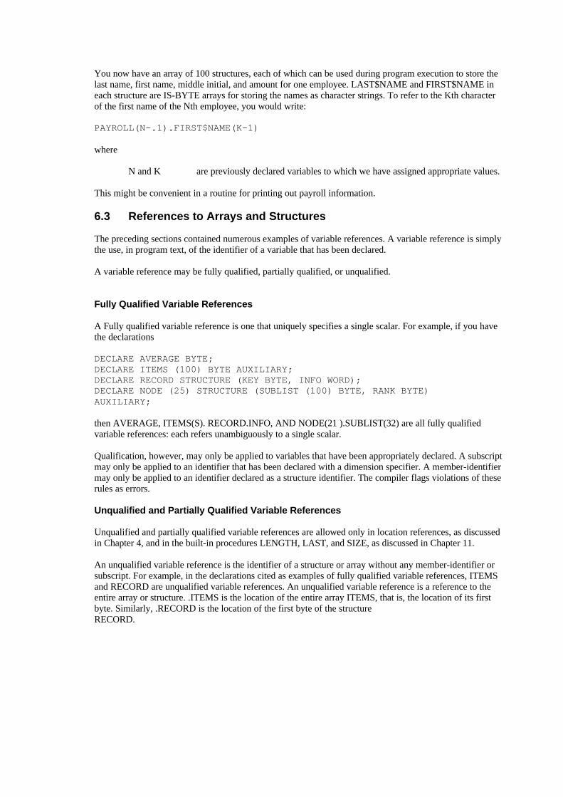
You now have an array of 100 structures, each of which can be used during program execution to store thelast name, first name, middle initial, and amount for one employee. LAST$NAME and FIRST$NAME ineach structure are IS-BYTE arrays for storing the names as character strings. To refer to the Kth characterof the first name of the Nth employee, you would write:
PAYROLL(N-.1).FIRST$NAME(K-1)
where
N and K are previously declared variables to which we have assigned appropriate values.
This might be convenient in a routine for printing out payroll information.
6.3 References to Arrays and Structures
The preceding sections contained numerous examples of variable references. A variable reference is simplythe use, in program text, of the identifier of a variable that has been declared.
A variable reference may be fully qualified, partially qualified, or unqualified.
Fully Qualified Variable References
A Fully qualified variable reference is one that uniquely specifies a single scalar. For example, if you havethe declarations
DECLARE AVERAGE BYTE;DECLARE ITEMS (100) BYTE AUXILIARY;DECLARE RECORD STRUCTURE (KEY BYTE, INFO WORD);DECLARE NODE (25) STRUCTURE (SUBLIST (100) BYTE, RANK BYTE)AUXILIARY;
then AVERAGE, ITEMS(S). RECORD.INFO, AND NODE(21 ).SUBLIST(32) are all fully qualifiedvariable references: each refers unambiguously to a single scalar.
Qualification, however, may only be applied to variables that have been appropriately declared. A subscriptmay only be applied to an identifier that has been declared with a dimension specifier. A member-identifiermay only be applied to an identifier declared as a structure identifier. The compiler flags violations of theserules as errors.
Unqualified and Partially Qualified Variable References
Unqualified and partially qualified variable references are allowed only in location references, as discussedin Chapter 4, and in the built-in procedures LENGTH, LAST, and SIZE, as discussed in Chapter 11.
An unqualified variable reference is the identifier of a structure or array without any member-identifier orsubscript. For example, in the declarations cited as examples of fully qualified variable references, ITEMSand RECORD are unqualified variable references. An unqualified variable reference is a reference to theentire array or structure. .ITEMS is the location of the entire array ITEMS, that is, the location of its firstbyte. Similarly, .RECORD is the location of the first byte of the structureRECORD.

A partially qualified variable reference fails to refer uniquely to a single scalar even 1using a subscript and/ or member-identifier with an identifier. For example, given the declarations cited as examples of fullyqualified variable references, NODE( 15) and NODE(12).SUBLIST are partially qualified variablereferences.
When used with the dot operator, such references are taken to mean the first byte that could fit thedescription. Thus, .NODE( 15) is the location of the first byte of the structure NODE(15), which itself is anelement of the array NODE. Similarly..NODE(12).SUBLIST is the location of the first byte of the array NODE(12).SUBLIST. which itself is amember of the structure NODE(12), which in turn is an element of the array NODE.
Note that .NODE.SUBLIST is not permitted because it is completely ambiguous: in a location referencereferring to an array made up of structures, a subscript must be given before a member-identifier can beadded to the reference. The rule is different for partially qualified variable references in connection with thebuilt-in procedures LENGTH. LAST, and SIZE, as explained in Chapter 11.

Flow Control Statements 7This chapter describes statements that alter the sequence of execution of PL/M-5l statements and groupstatements into blocks.
7.1 DO and END Statements: DO Blocks
Procedures and DO blocks are the basic units of modular programming in PL/M-51. (Procedures arediscussed in Chapter 10.)
This chapter discusses all four kinds of DO-blocks: the simple DO block, the DO CASE block, the DOWHILE block, and the iterative DO BLOCK. Each DO-block begins with a DO statement and includes allsubsequent statements through the closingEND statement. Following are examples of the four kinds of DO-blocks.
• The simple DO block
DO; /* all statement, executed, each in order */statement-0;statement-1;statement-2;..END;
• The DO CASE block
DO CASE select_expression; /* exactly one statement executed */
case-0-statement; /* executed If select_expression = 0 */case-1-statement; /* executed if select_expression = 1 */. /* etc */.END;
• The DO WHILE block
DO WHILE expression_true; /* repeated while expression is true */statement-0; /* none if expression false. */statement-1;..END;
• The iterative DO block
DO counter = start-expr TO limit-expr BY step-expr;statement-0;./* all statements executed a number */statement-1; /* of times depending on comparison */ /* of counter with limit-expr */
. END;

The DO WHILE block and the iterative DO block are also referred to as DO-loops because the executablestatements within them may be executed repeatedly (in sequence) depending on the expressions in the DOstatement.
Any DO statement may have multiple labels on it, and the last (only) of these may appear between theword END and the next semicolon. For example:
A: B: C: D: EM: DO; . . . END EM ; /* indicates end of block EM; */ /* A, B, C, D also end here. */
As previously stated, the placement of declarations is restricted. Except in procedures, declarations arepermitted only at the top of a simple DO block before any executable statements of the block. (This DOcan, of course, be nested within other DOs or procedures. Chapter 9 discusses the scope of declarednames.)
Each DO block can contain any sequence of executable statements, including other DO blocks. Each blockis considered by the compiler as a unit, as if it were a single executable statement. This fact is particularlyuseful in the DO CASE block and theIF statement, both of which are discussed later in this chapter.
Only simple DO blocks may also contain DECLARE statements, which declare local variables. Suchdeclarations must precede all executable statements in the block.
The discussions that follow describe the normal flow of control within each kind of DO block. The normalexit from the block passes through the END statement to the statement immediately following it. None ofthe statements in the blocks in the following discussions are assumed to cause control to bypass thatprocess. A GOTO statement with the target outside the block would be one such bypass. (GOTOs arediscussed later in this chapter.)
Simple DO Blocks
A simple DO block merely groups, as a unit, a set of statements that will be executed sequentially (exceptfor the effect of GOTOs or CALLs). For example,
DOstatement-0;statement-1;. . .statement-n;
END;
Another example of a simple DO block is:
DO;NEW$VALUE = OLD$VALUE + TEMP;COUNT = COUNT + 1;
END;
The second simple DO block adds the value of TEMP to the value of OLD$VALUE and stores it inNEW$VALUE. It then increments the value of COUNT by one.

DO blocks may be nested within each other, as shown in the following example:
able: DO;statement-0;statement-1;
baker: DO; statement-a; statement-b; statement-c; END baker; statement -2; statement-3;
END able;
In the example just cited, the first DO statement and the second END statement bracket one simple DOblock. The second DO statement and the first END statement bracket a different DO block inside the firstone. Indentation (using tabs or spaces) is used to make the sequence readable; thus, it is easy to see that oneDO block is nested inside another. Nesting, permitted up to 16 levels, is highly recommended for writingPL/M-5l programs.
A simple DO block can delimit the scope of variables, as discussed in Chapter 9.
DO CASE Blocks
A DO CASE block begins with a DO CASE statement, and selectively executes one of the statements inthe block. The statement is selected by the value of an expression. The maximum number of cases is 84.The form of the DO CASE block is:
DO CASEstatement-0;statement-1;. . .statement-n;
END;
statement-0 through statement-n can also be DO blocks.
In the DO CASE statement, expression must yield a BYTE or WORD value. If it is a constant expression,it is evaluated as if it were being assigned to a BYTE variable. The value of expression must lie between 0and n (call the value K). K is used to select one of the statements in the DO CASE block. which is thenexecuted. The first case (statement-0) corresponds to K = 0, the second (statement-1) corresponds to K = 1,and so forth. Only one statement from the block is selected. This statement is then executed only once.Control then passes to the statement following the END statement of the DO CASE bock.
- CAUTION -
If the run time value-of the expression in the DO CASE statement is greater than n (where n + 1 is thenumber of cases in the DO CASE block), then the effect of the DO CASE statement is undefined. This maydisastrously effect program execution. Therefore, if any chance exists for this out-of-range condition tooccur, the DO CASE block should be contained within an IF statement, which will test the expression tomake sure that it has a value that will produce meaningful results.
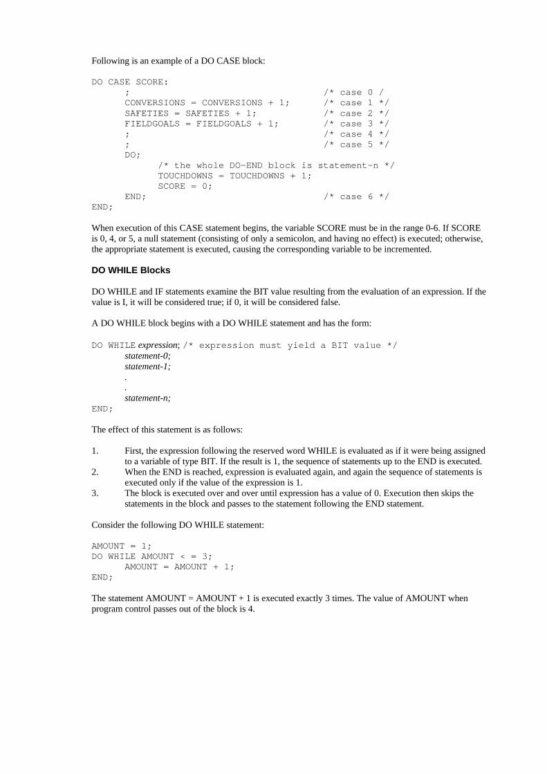
Following is an example of a DO CASE block:
DO CASE SCORE:; /* case 0 /CONVERSIONS = CONVERSIONS + 1; /* case 1 */SAFETIES = SAFETIES + 1; /* case 2 */FIELDGOALS = FIELDGOALS + 1; /* case 3 */; /* case 4 */; /* case 5 */DO;
/* the whole DO-END block is statement-n */TOUCHDOWNS = TOUCHDOWNS + 1;SCORE = 0;
END; /* case 6 */END;
When execution of this CASE statement begins, the variable SCORE must be in the range 0-6. If SCOREis 0, 4, or 5, a null statement (consisting of only a semicolon, and having no effect) is executed; otherwise,the appropriate statement is executed, causing the corresponding variable to be incremented.
DO WHILE Blocks
DO WHILE and IF statements examine the BIT value resulting from the evaluation of an expression. If thevalue is I, it will be considered true; if 0, it will be considered false.
A DO WHILE block begins with a DO WHILE statement and has the form:
DO WHILE expression; /* expression must yield a BIT value */statement-0;statement-1;..statement-n;
END;
The effect of this statement is as follows:
1. First, the expression following the reserved word WHILE is evaluated as if it were being assignedto a variable of type BIT. If the result is 1, the sequence of statements up to the END is executed.
2. When the END is reached, expression is evaluated again, and again the sequence of statements isexecuted only if the value of the expression is 1.
3. The block is executed over and over until expression has a value of 0. Execution then skips thestatements in the block and passes to the statement following the END statement.
Consider the following DO WHILE statement:
AMOUNT = 1;DO WHILE AMOUNT < = 3;
AMOUNT = AMOUNT + 1;END;
The statement AMOUNT = AMOUNT + 1 is executed exactly 3 times. The value of AMOUNT whenprogram control passes out of the block is 4.

Iterative DO Blocks
An iterative DO block begins with an iteration statement and executes each statement in the block in order,repeating the entire sequence as described in the following paragraphs. The form of the iterative DO blockis:
DO counter = start-expr TO limit-expr BY step-expr;statement -0statement-1;...
END;
The BY step-expr phrase is optional: if it is omitted, a step value of 1 is the default.
The counter must be a simple (i.e., non-BASED, non-subscripted) variable of type BYTE or WORD. Thestart-expr, limit-expr, and step-expr may be any valid PL/M-51 expressions, also of BYTE or WORDtypes.
The iterative DO is equivalent to:
Counter= start-expr;DO WHILE counter <- limit-expr;
statement -0;statement-1;...counter = counter + step-expr;
/* if this causes counter to overflow, exit the WHILE loop */END;
Following is an example of an iterative DO block.
DO I = 1 TO 10;CALL BELL;
END;
where
BELL is the name of a procedure that causes a bell to be rung.
The bell is rung ten times.
The following iterative DO block example shows how the index-variable can be used within the block.
AMOUNT = 0;DO I = 1 TO 10;
AMOUNT = AMOUNT + I;END;
The assignment statement is executed 10 times, each time with a new value for I. The result is to sum thenumbers from 1 to 10 (inclusive) and to leave the sum (namely, 55) as the value of AMOUNT.

The next iterative DO block example uses the “BY step_expr” construct.
/* Compute the product of the first N odd integers */PROD = 1;DO I = 1 TO (2 * N-1) BY 2;
PROD = PROD + I;END;
The following distinctions can be important.• In every case, Start-expr is evaluated only once and limit-expr is evaluated before any execution.• A negative step does not exist. For example, if step-expr is -5, and the counter is a BYTE, 251 is
used. Furthermore, stepping down to a limit-expr that is less than start-expr is not possible becausethe loop will be exited immediately.
-CAUTION-
If you have a BYTE counter, but limit-expr or step-expr are WORDs, the semantics of the iterative DOmay be different from what you would expect.
7.2 The IF Statement
The IF statement provides conditional execution of statements. It takes the form:
IF expression THEN statement_a;ELSE statement_b: /* optional */
The reserved word THEN and the statement following it are required; they are called the THEN part.” Thereserved word ELSE and the statement following it are optional; they are called the “ELSE part.”
The IF statement has the following effect: the expression is evaluated as if it were being assigned to avariable of type BIT
If the result is true (i.e., 1) statement_a is executed. If the result is false (i.e., 0), statement_b is executed.Following execution of the chosen alternative, control passes to the next statement following the IFstatement. Thus, one and only one of the two statements (statement_a and statement_b) is executed.
Consider the following program fragment:
IF NEW > OLD THEN RESULT = NEW;ELSE RESULT = OLD;
RESULT is assigned the value of NEW or the value of OLD, whichever is greater. This code causesexactly one of the two assignment statements to be executed. RESULT always gets assigned some value,but only one assignment to RESULT is executed.
If statement_b is not needed, the ELSE part may be omitted entirely. An IF statement with the ELSE partomitted takes the form:
IF expression THEN statement_a

Statement_a is executed if the value of expression is 1 (true). Otherwise, nothing happens and controlimmediately passes to the next statement following the IF statement.
For example. the following sequence of PL/M-51 statements will assign INDEX the number 5 or the valueof THRESHOLD, whichever is larger. The value of INIT will change during execution of the IF statementonly if THRESHOLD is greater than 5. In any case, the final value of INIT is copied to INDEX.
INIT = 5;IF THRESHOLD > INIT THEN INIT = THRESHOLD;INDEX = INIT;
The power of the IF statement is enhanced by using DO blocks in the THEN and ELSE parts. Since a DOblock is allowed wherever a single statement is allowed. each of the two statements in an IF statement maybe a DO block. For example:
IF A = B THENDO;
EQUAL$EVENTS = EQUAL$EVENTS + 1;PAIR$VALUE = A;BOTTOM = B;
END;
ELSEDO;
UNEQUAL$EVENTS = UNEQUAL$EVENTS + 1;TOP = A;BOTTOM = B;
END;
DO blocks nested within an IF statement can contain Further nested DO blocks, IF statements, variable andprocedure declarations, and so on.
Nested IF Statements
Any IF statement (including the ELSE part, if any) may be considered a single PL/M-5l statement(although it is not a block). Thus, the statement to be executed in a THEN or an ELSE clause may in fact beanother IF statement.
An IF statement inside a THEN clause is called a nested IF. Nesting may be carried to several levelswithout enclosing any of the nested IF statements in DO blocks, as in the following construction:
IF expression-1 THENIF expression-2 THENIF expression-3 THEN statement-a;
The example just given has three levels of nesting. Note that statement-a will be executed only if the valuesof all three expressions are true. Thus, the construction just cited is equivalent to:
IF (expression-1) AND (expression-2) AND (expression-3) THEN statement-a;

Note: the example of nesting just given has no ELSE part. If you have nested IFs, with as many ELSEclauses as IFs, you have only one valid way to match IFs and ELSEs. For instance (matching clauses areindented equally-deep):
IF BOOLEAN(foo) THEN IF gorp>4 THENELSEELSE
If no ELSE clauses are present, matching up will be no problem. But, if the IF clauses outnumber the ELSEclauses, only one way will exist to match ELSE clauses to IFs. If the example just given had only oneELSE, it could be interpreted as:
IF BOOLEAN(foo) THEN IF gorp>4 THENELSE
or as:
IF BOOLEAN(foo) THEN IF gorp>4 THENELSE
The ambiguity is resolved by matching an ELSE clause to the nearest (as yet unmatched) IF clause thatcomes before it; thus, the first of the two interpretations just cited is correct.
Sequential IF Statements
Consider the following case: an ASCII-coded character is stored in a BYTE variable named CHAR. If thecharacter is an A. you want to execute statement-a. If the character is a B, you want to execute statement-b.If the character is a C, you want to execute statement-c. If the character is not A, B, or C, you want toexecute statement-x. The code for executing statement -x could be written as follows using IF statementscompletely independent of one another.
IF CHAR = ‘A’ THEN statement-a;IF CHAR = ‘B’ THEN statement-b;IF CHAR = ‘C’ THEN statement-c;IF CHAR <> ‘A’ AND CHAR > ‘B’ and CHAR <> ‘C’ THEN statement-x;
The sequence just given is inefficient because all four IF statements (six tests in all) will be carried out inevery case, which is wasteful when one of the earlier tests succeeds.
You need to test for ‘A’ in all cases. But, you need to test for ‘B’ only if the test for ‘A’ fails; you need totest for ‘C’ only if both previous tests fail. Finally, if the tests for A, B, C all fail, no further tests areneeded—you must execute statement-x. To improve the code, rewrite it as follows.
IF CHAR = ‘A’ THEN statement-a;ELSE IF CHAR = ‘B’ THEN statement-b;ELSE IF CHAR = ‘C’ THEN statement-c;ELSE statement-x;
Note: this sequence is not a case of nested IF statements as described in the preceding section. IFstatements are said to be nested only when an IF statement is inside the
THEN part of another IF statement. In the example just given, you have IF statements inside the ELSEparts of other IF statements. This construction is called sequential IF statements. It is equivalent to thefollowing construction:
IF CHAR = ‘A’ THEN statement-a;ELSE DO;
IF CHAR = ‘B’ THEN statement-b;ELSE DO;
IF CHAR = ‘C’ THEN statement-c;ELSE statement-x;
END;END;
Sequential IF statements are useful whenever a set of tests is to be made, but you should skip the remainingtests whenever one of the tests succeeds. This construction works because all the remaining tests are in theELSE part of the current test. See the DO CASE for a possible alternative.
7.3 GOTO Statements
A GOTO statement alters the sequential order of program execution by transferring control directly to alabeled statement. Sequential execution then resumes, beginning with the target statement. The GOTOstatement has the following form:
GOTO label;
The following is an example of a GOTO statement:
GOTO ABORT;
The appearance of label in a GOTO statement is not a label definition it is a label reference.
The reserved word GOTO can also be written GO TO. with an embedded blank.
For reasons discussed in Chapter 9, GOTO statements are restricted. The only possible GOTO transfers arethe following:
• From a GOTO statement in the outer level of some block to a labeled statement in the outer levelof the same block.
• From a GOTO statement in an inner block to a labeled statement in the outer level of an enclosingblock (not necessarily the smallest enclosing block). However. if the inner block is a procedureblock, the transfer may only be to a statement in the outer level of the main program module.
• From any point in one program module to a labeled statement in the outer level of the mainprogram module. To jump to such a label, you must declare the label to have extended scope, i.e.,declare it PUBLIC in the main module and EXTERNAL in the module containing the GOTO. Themain program and the procedure containing the GOTO must use the same register-bank (seeUSING in Chapter 10).
GOTOs are necessary in some situations. However, when control transfers are desired, an iterative DO, DOWHILE, DO CASE, IF, or a procedure activation (see Chapter 10) is preferable. Indiscriminate use ofGOTOs will result in a program that will be difficult to understand, correct, and maintain.

7.4 The CALL and RETURN Statements
The CALL and RETURN statements are discussed in detail in Chapter 10. They are mentioned here onlybecause they control program-flow.
The CALL statement is used to activate an untyped procedure (one that does not return a value).
The RETURN statement is used within a procedure body to cause a return of control from the procedure tothe point from which it was activated.
7.5 The Null Statement
A null statement contains nothing (except spaces and comments) before its terminating semicolon. It is anexecutable statement that has no effect whatsoever on a program. It may or may not be labeled. Also, a nullstatement is useful as part of a DO CASE construct.

Sample Program 1 8At this point, all of the constructions available in PL/M-51, except procedures, have been examined. Acomplete PL/M-51 program can now be considered.
8.1 Insertion Sort Algorithm
The sample program in this chapter implements a straight insertion sort algorithm based on Knuth’sAlgorithms in The Art of Computer Programming, Vol. 3, page 81.Readers who refer to Knuth’s algorithm should note the following differences between his algorithm andthe one implemented in the sample program:• The algorithm has been adapted to PL/M-51 usage by using an array of structures to represent the
records to be sorted. The sort key for each record is a member of the structure for that record.• The algorithm has been modified by using a DO WHILE block to achieve the same logical effect
as the GOTOs implied in steps S3 and 54 of Knuth’s algorithm.• The index I is used in a slightly different manner (it is initialized to J instead of J-1).
The effect of the algorithm is to arrange 50 records in order according to the values of their keys, with thesmallest key at the beginning (lowest location) and the largest key at the end (highest location).
The sorting method is as follows. Assume that the records are all in memory, stored as an array ofstructures. The key for each record is a member of the structure.
Now, go through the array from the second record (record number I) upwards. When you reach any givenrecord (the current record), you will already have sorted the preceding records. (The first time through,when you look at record number 1, record number 0 is the only preceding record.)
Take the current record, store it temporarily in, a buffer, and look backwards through the preceding recordsuntil you find one whose key is not greater than that of the current record. Then, put the current record justafter this record.
Following is a sample program (shown in figure 8-I) and a detailed explanation. Study the program and theexplanation until you understand how the program works (especially the DO WHILE block, which iscontrolled by a more complex conditionexpression than you have seen up to this point).
Now, consider the text of this program. First, declare the following variables:
• RECORD—an AUXILIARY array of 50 structures to hold the 50 records. Each structure has aBYTE member that is the sort key, and a WORD member that could contain anything (in aworking program, this would be the data content of the record).
• CURRENT—a structure used as a buffer to hold the current record while you look back throughthe records already sorted. Its members are like those of one structure element of RECORD.
• J - which will be used as an index variable in an iterative DO statement. J is always the subscriptof the current record. When J becomes greater than 49, the sort is completed.

M: DO;DECLARE RECORD(50) STRUCTURE (KEY BYTE , INFO WORD ) AUXILIARY;DECLARE CURRENT STRUCTURE (KEY BYTE,INFO WORD)DECLARE (J,I) BYTE;
/* data is read in ,to initialize records */
SORT : DO J = 1 to 49;CURRENT.KEY = RECORD(J).KEY;CURRENT.INFO = RECORD(J).INFO;I = J;
FIND: DO WHILE I >0 AND RECORD(I-1).KEY > CURRENT.KEY;RECORD(I).KEY = RECORD(I-1).KEY;RECORD(I).INFO = RECORD(I-1).INFO;I = I-1
END FIND;
RECORD(I).KEY = CURRENT.KEY;RECORD(I).INFO = CURRENT.INFO;
END SORT
/* Data is written out from the records */
END M; /* end of module */
Figure 8-1. insertion Sort Algorithm
• I—which will be used like an index variable in controlling a DO WHILE block. I-1 is always thesubscript of a previously sorted record.
A working program would include code to read data into the array RECORD. At the end of the program,enough code would be generated to write out the data from RECORD. In this example, you omit this codebecause it would make the example-too lengthy and because the method used for I / O would depend on the particular system used to executethe program. Comments have been inserted in place of this code.
The executable part of the program is organized as two DO blocks, one nested within the other. The outerblock (labeled SORT) is an iterative DO block that goes through the records one at a time. The recordselected by the index variable J each time through this block is the current record. (Notice that J is never 0.Because of the way the algorithm is defined, you must have a preceding element to look back at; so, youstart with the second element of the array and look back at the first.)

The first two assignment statements in the block transfer the current record into CURRENT. The nextstatement sets the initial value for I, which will be used to control the inner block.
The inner block (labeled FIND) is the one that looks back through previously sorted records to find theright place to put the current record. The way this block is controlled is worth examining. The variable I isused like an index variable in an iterative DO, but it is changed explicitly inside the block, instead ofautomatically as in an iterative DO statement. The DO WHILE construction is used instead of an iterativeDO because it allows two or more tests to be combined—in this case, by means of an AND operator.
I is set to J before the first time through the DO WHILE block and decremented each time through. As longas I remains greater than 0, the first half of the DO WHILE condition is satisfied.
The value I-1 is the subscript of the record being looked back at. The second half of the DO WHILEcondition is that the key of this record must be greater than, the key of the current record.
You are looking for a previously sorted record whose key is not greater than the key of the current record.Thus, the condition in the DO WHILE statement will cause the DO WHILE block to be executedrepeatedly until such a record is found, or until I reaches 0 (meaning that all previously sorted records havebeen examined).
Each time the DO WHILE block is executed, it moves the (I-1)th record up into the Ith position, and thendecrements I.
When the condition in the DO WHILE statement is not met, one of the following is true:
• I = 0 because you have looked through all the previously sorted records without finding onewhose key is not greater than that of the current record. All of the previously sorted records havebeen moved up by one.
• I-1 is the subscript of a record whose key is not greater than the key of the current record. All ofthe previously sorted records whose keys are greater than that of the current record have beenmoved up by one.
In either case, the failure of the DO WHILE condition means that the current record (being held inCURRENT) belongs in the Ith position. It is transferred into this position by the two assignment statementsthat form the remainder of the outer DO block.
To consider the next unsorted record, the outer DO block is repeated with an incremented value of J.
Notice that the entire program is contained within a simple DO block labeled M. This makes it a module.

Block Structure, Scope,9and Lifetimes Rules
This chapter is intended to clarify the meaning of outer level and the concept of scope, including the use ofthe linkage attributes, PUBLIC and EXTERNAL. Lifetime rules will also be explained.
9.1 Scope
The outer level of a block means statements (or labels) contained in the block but not contained in anynested blocks. The term exclusive extent also has this meaning. The inner level, or inclusive extent, includesthis outer level and all nested blocks as well.
A block at the same level as another block means both are contained by exactly the same outer blocks.
The scope of an object means those parts of a program where its name, type, and attributes are recognized,i.e., handled according to a given declaration. An object means a variable, label, procedure, or symbolic(named) constant (i.e., a compilation constant or execution constant as discussed in Chapter 3).
A program is the complete set of modules that are ultimately linked together and located as a unit.
These definitions are explained further by the text and examples that follow.
9.2 Names Recognized within Blocks
PL/M-5l, like Pascal, is a block-structured language.
You create blocks of code containing declarations, followed by executable statements. You order and nestthe blocks in such a way as to simplify and clarify the flow of data and control. (The maximum nest is 16blocks deep.) A collection of these blocks that performs a single function, or a small set of relatedfunctions, is usually compiled as one module.
Beyond the advantages of modularity, simplicity, and clarity, the nesting of blocks serves another verybasic purpose: names declared at an outer level are known to all statements of all nested blocks as well.
You can always declare a new meaning for any such name within a nested simple-DO or procedure block,thereby cutting off its earlier meaning for this block. But, if you don’t choose this option, its meaning isestablished by a single declaration at an outer level. (The only objects that don’t require declarations priorto use are labels.)
In figure 9-1, everything inside the solid line constitutes the inclusive extent of block MMM (in this case,module MMM). KK is known throughout this block, including within all nested blocks.
Everything inside the dashed line constitutes the inclusive extent of block SORT. JJ and II is knownthroughout this block, but not outside it, that is, not before the label SORT or after the END SORTstatement.

MMM: DO; /* Beginning of module */DECLARE RECORD (50) STRUCTURE(KEY BYTE,INFO WORD) AUXILIARY;
DECLARE CURRENT STRUCTURE(KEY BYTE,INFO WORD);
DECLARE KK BYTE:KK = 49;
/* Instructions here would read in data */
SORT: DO;
DECLARE (JJ,II) INTEGER;DO JJ = 1 TO 49;
CURRENT.KEY = RECORD(JJ).KEY;CURRENT.INFO = RECORD(JJ).INFO;
FIND: DO WHILE II > 0 ANDRECORD(II-1).KEY > CURRENT.KEY;RECORD(II).KEY = RECORD(II-1).KEY;RECORD(II).INFO = RECORD(II-1).INFO;II = II-1
END FIND;
RECORD(II).KEY = CURRENT.KEY;RECORD(II).INFO = CURRENT.INFO;
END;
END SORT;
/* Instructions here would write out data from the records *
END MMM; /* End of module */
Figure 9-1. Inclusive Extent of Blocks
Everything inside the dotted line constitutes the inclusive extent of block FIND. Since this is not a simple-DO or procedure block, declarations are not allowed. All prior declarations shown are available for usewithin FIND.
See also figure 9-2.
The shaded area is the exclusive extent (the outer level) of block SORT. The unshaded area within SORT isthe exclusive (and inclusive) extent of block FIND. To the instructions within the FIND block, SORT’sexclusive extent is an outer level. The outermost level (or module level) is the area outside the solid linesenclosing the SORT block.’

MMM: DO; /* Beginning of module */DECLARE RECORD (50) STRUCTURE(KEY BYTE,INFO WORD) AUXILIARY;
DECLARE CURRENT STRUCTURE(KEY BYTE,INFO WORD);
DECLARE KK BYTE:KK = 49;
/* Instructions here would read in data */
SORT: DO;
DECLARE (JJ,II) INTEGER;DO JJ = 1 TO 49;
CURRENT.KEY = RECORD(JJ).KEY;CURRENT.INFO = RECORD(JJ).INFO;
FIND: DO WHILE II > 0 ANDRECORD(II-1).KEY > CURRENT.KEY;RECORD(II).KEY = RECORD(II-1).KEY;RECORD(II).INFO = RECORD(II-1).INFO;II = II-1
END FIND;
RECORD(II).KEY = CURRENT.KEY;RECORD(II).INFO = CURRENT.INFO;
END;
END SORT;
/* Instructions here would write out data from the records *
END MMM; /* End of module */
Figure 9-2. Outer Level of Block SORT
9.3 Restrictions on Multiple Declarations
In any given block, a known name cannot be redeclared at the same level as its original declaration. A newdeclaration is permitted inside a nested simple-DO or procedure block, where it automatically identifies anew object despite the existence of the same name at a higher level. The new object will be the only oneknown by this name within its block, and it will be unknown outside its block, where the prior namemaintains its meaning. These observations also apply when a name is redeclared in another block at thesame level as the block containing the original declaration.
When a name is declared only in a separate block at the same level, it can only be accessed in that blockwhere it was declared. The definition is not at an outer level to the block in which you are notprogramming. Any local declaration you supply will establish a new separate object whose values bear norelation to those of the other.
The reason for these rules, as for many in programming, is that each name in the program mustunambiguously define address / location. The declaration rules given in the first paragraph of this sectiongive you freedom to choose whatever names seem appropriate within a given block without interfering withexterior uses of them. But, when you redeclare a name, its outer-level meaning is inaccessible untilexecution exits the block containing the new declaration. For example:
A: DO;DECLARE X, Y, Z BYTE;
L1: X = 2;Y = X;Z = X;
B: DO;DECLARE X, Y BYTE;X = 3 ;Y = X
L2: Z = X;END B;L3: /* At this point, X = 2, Y = 2, Z = 3, because the value of the
redeclared X was used to fill Z *//* If statement L2 were outside the DO block labeled B, Z would be 2 because the outer X value would be used. */
9.4 Lifetime Rules
Given the following block:
MY_BLOCK: DO;DECLARE (X,Y,Z) ... ;....
END MY_BLOCK;
X, Y and Z become inaccessible as soon as the END MY_BLOCK statement is executed. Since X, Y and Zare no longer accessible, the memory locations they occupy become available for other uses, exactly theway they would be in Pascal. The next time your program enters this block, do not be surprised if thevalues of X, Y and Z are entirely different from what they were when END MY_BLOCK was executed.Note that, if you enter a block nested within MY_BLOCK, the space occupied by X, Y and Z will not beavailable for reuse, even if (due to redeclarations) they become inaccessible.
If a block contains CALLs (or function references), that block’s variables may also become inaccessiblewhile the procedure it calls is executing. But, since execution of the block will resume as soon as theprocedure returns, the variables do not let go of the space they use. Thus. X = X + FUNC(Y) will work asexpected: the call to FUNC is guaranteed not to wipe out X. The same goes for IF X = 7 THEN CALLPROC. This rule, like the one in the previous paragraph, also applies to Pascal.
9.5 Extended Scope: The PUBLIC and EXTERNAL Attributes
The PUBLIC and EXTERNAL attributes permit you to extend the scope of names for all objects exceptmodules; a module name may not be declared with either attribute.

To extend the scope means to make the names available for use in modules other than the one where theyare defined (the names are already available to nested blocks in this module.) To be specific, this includesnames of variables, labels, procedures, and execution CONSTANTs.
For example. the statement:
DECLARE FLAG BIT PUBLIC;
causes a BIT to be allocated, named FLAG, and its address made known to any other module where thefollowing declaration occurs:
DECLARE FLAG BIT EXTERNAL;
Similarly, if one module has a procedure declaration block that begins:
SUMMER : PROCEDURE (A,B) BIT PUBLIC;DECLARE (A,B) BYTE;/* other declarations can go here *//* executable statements go here */
END summer
Then any other module may invoke SUMMER if it first declares :
SUMMER : PROCEDURE (A,B) BIT EXTERNAL;/* A,B can be any names */DECLARE (A,B) BYTE;/* but these names must match them, and each type must match its public definition */
END SUMMER;
Since ambiguity of location or definition is not permissible, the use of PUBLIC and EXTERNAL mustfollow a strict set of rules, as follows:
1. These attributes may only be used in a declaration at the outermost level of a module, i.e., never ina nested block.
2. Only one may appear on any declaration, and only once. Thus,DECLARE ZETA BYTE PUBLIC EXTERNAL; /* error */DECLARE RHO WORD PUBLIC PUBLIC ; /* error */and similar constructs are all invalid.
3. Names may be declared PUBLIC at most once. The PUBLIC declaration is the definingdeclaration: the address it creates is used in each procedure or module where the same name isdeclared EXTERNAL. You must not create more than one PUBLIC address for any name.
4. Names may only be declared EXTERNAL if they are also declared PUBLIC in a different moduleof the program. The EXTERNAL attribute is essentially a request to use a PUBLIC address. AnEXTERNAL without a PUBLIC is a dead letter. Lack of a definition elsewhere will result in alink-time error.
5. The location where the name is declared EXTERNAL must be given the same type and addressspace as the location where it is declared PUBLIC. Any contradiction of type, although notdetected by the compiler, would violate the intention to use the location(s) and content(s) definedelsewhere and will probably cause run-time errors.

6. Similarly, a name declared EXTERNAL must not be given a location, i.e., with the AT phrase, oran initialization, i.e., using CONSTANT(...). Such usage would again contradict being defined inanother module. However, in that other module, where this name is declared PUBLIC, the use ofAT or CONSTANT(...) is allowed with it.
7. Neither PUBLIC nor EXTERNAL may be applied to a name that is based. For example.
DECLARE PTR1 WORD;DECLARE V1 BASED PTR1 PUBLIC;
is invalid. The reason: by definition, V1 has no home of its own; its location is always determinedby PTR1. Thus to declare V1 PUBLIC or EXTERNAL does not permit the correct assignment ofaddresses. PTR1, on the other hand, always contains the current address of V1. Declaring the base,PTR1 in this case, to be PUBLIC or EXTERNAL is always permissible.
9. A register cannot be declared PUBLIC or EXTERNAL.
(Three additional restrictions on the use of EXTERNAL procedures appear in Chapter 10.)
Following the rules just given will permit consistent and reliable execution of programs using names withextended scope. A PUBLIC definition occurring in one module will then be used by all related referencesto that name in separate modules, that is, references which declare the name EXTERNAL. An example of aPUBLIC definition occurring in one module follows,
MOD1: DODECLARE V1 BYTE PUBLIC;...
END MOD;
MOD2: DO; DECLARE V1 BYTE EXTERNAL;
QQ4: PROCEDURE PUBLIC;...END QQ4
END MOD2;
Both references to V1 will use the same definition (location) for V1, namely, that in module MOD1.Similarly, if any module needed to call procedure QQ4, it would first need a declaration like the one thatfollows—
QQ4: PROCEDURE EXTERNAL;END QQ4
so that a subsequent CALL QQ4 would correctly pass control to that procedure in module MOD2.
9.6 Scope of Labels and Restrictions on GOTOs
Labels are subject to exactly the same rules of scope discussed in the previous section.
One consequence is that a label is unknown outside the block where it is declared. As discussed earlier, alabel is either declared explicitly at the beginning of a simple-DO or procedure block, or the compilerconsiders it declared there as soon as it is defined (by appearing in front of a colon) anywhere in the block.Therefore, the discussion of what names are known in which blocks applies directly to labels as well as toother names.

The label on a block is not part of the block it names. For example, the name on the DO enclosing themodule itself is not part of that block; it merely names it. For nested blocks, a label is again not part of theblock it names, but belongs instead to the outer level, as part of that first enclosing block.
If a name used as a label on a block is defined inside that block, it will name something new, whether it is alabel, variable, or constant. This fact leads to important restrictions on use of the GOTO statement:1. It is impossible for a GOTO to transfer control from an outer block to a labeled statement inside a nestedblock.
2. Moreover, a GOTO can transfer control from one block to another in the same module only if the targetblock encloses the one containing the GOTO (and only if the name of that target label is not declared in thenested block.)
Furthermore, a label with the PUBLIC attribute is permitted only in the main module. (This forces all othertransfers of control, that is, those not involving a return to the main module, to use procedure calls. Forcingall other transfers of control to use procedure calls favors the development of orderly, modularized,traceable programs.)
Following are some examples of valid and invalid GOTOs.
DO;X: DO;
DO;GOTO X; /* valid - X is in an outer block */
END;END;
END;
. . . . .
GOTO Y; /* invalid - Y is in an Inner block */DO;
Y:END;
. . . . .
DECLARE L LABEL EXTERNAL; /* L must be in module-level code */DO; GOTO L; /* valid */END;

Procedures and Interrupts 10A procedure is .a section of PL/M-51 code that is declared and then activated from other parts of theprogram. A function reference or CALL statement activates the procedure. causing the procedure code tohe executed: program control is transferred from the point or activation to the beginning or. the procedurecode, the code is executed, and upon return from the procedure code, program control is passed back to thestatement immediately after the point of activation.
The use of procedures forms the basis of modular programming. It facilitates making and using programlibraries, eases programming and documentation, and reduces the amount of object code generated by aprogram. The following sections review how to declare procedures, and describe how to activateprocedures.
10.1 Procedure Declarations
You must declare procedures, just as you must declare variables. Thereafter, any reference to a proceduremust occur within the scope defined by the procedure declaration. Also, a procedure may not be used(called, or invoked in an expression) until after the END statement of the procedure declaration.
A procedure declaration consists of three parts: a PROCEDURE statement, a sequence of statementsforming the procedure body, and an END statement. The following is a simple example of a proceduredeclaration:
DOOR$CHECK : PROCEDURE;IF FRONT$DOOR$LOCKED AND SIDE$DOOR$LOCKED THEN
CALL POWER$ON;ELSE CALL DOOR$ALARM;
END DOOR$CHECK;
where
POWER$ON and DOOR$ALARM are procedures declared elsewhere in the same program.FRONT$DOOR$LOCKED and SIDE$DOOR$LOCKED are BIT variables declared elsewhere.
NOTEThe name in a PROCEDURE statement has the same appearance as a label definition; but, it is notconsidered a label definition, and a procedure name is not a label. PROCEDURE statements may not belabeled.
The name is a PL/M-51 identifier, which is associated with this procedure. The scope of a procedure isgoverned by the placement of its declaration in the program text, just as the scope of a variable is governedby the placement of its DECLARE statement (see Chapter 9 for a detailed description of the DECLAREstatement). Within this scope, the procedure can be activated by the name used in the PROCEDUREstatement.

A procedure declaration, like a DO block, controls the scope of variables (as described in Chapter 9). Also,like a simple DO block, a procedure declaration may contain DECLARE statements: these DECLAREstatements must precede the first executable statement in the procedure body.
As in a DO block, the identifier in the END statement has no effect on the program, but aids legibility anddebugging. If used, it must be the same as the procedure name.
Parameters
Formal parameters are non-based scalar variables declared within a procedure declaration whose identifiersappear in the parameter list in the PROCEDURE statement. The identifiers in the list are separated bycommas and the list is enclosed in parentheses. No subscripts or member-identifiers are allowed in theparameter list.
If the procedure has no formal parameters, the parameter list (including the parentheses) is omitted from thePROCEDURE statement.
Each formal parameter in the procedure statement must be declared as a non-based scalar variable in aDECLARE statement preceding the first executable statement in the procedure body. Formal parametersmay not be declared with a suffix (other than MAIN). However, procedure parameters are not storedaccording to the same rules as other declared variables. In particular, do not assume that a parameter isstored contiguously with other variables declared in the same factored variable declaration.
When a procedure that has formal parameters is activated, the CALL statement or function referencecontains a list of actual parameters. Each actual parameter is an expression whose value is assigned to thecorresponding formal parameter in the procedure before the procedure begins to execute, i.e., PL/M-51uses call by value for parameter passing.
For example, the following procedure takes four parameters, called PTR, N, LOWER, and UPPER. Itexamines N contiguously stored BYTE variables in MAIN memory. The parameter PTR is the location ofthe first of these variables. If any of these variables is less than the parameter LOWER or greater than theparameter UPPER, the ERRORSET procedure (declared elsewhere in the program) is activated.
RANGE$CHECK: PROCEDURE(PTR,N,LOWER,UPPER)DECLARE PTR WORD;DECLARE (N,LOWER,UPPER,I) BYTE;DECLARE ITEM BASED PTR (1) BYTE;
DO I = 0 TO N-1;IF (ITEM(I) <LOWER) OR (ITEM(I) > UPPER) THEN CALL ERRORSET;
/* ERRORSET Is a procedure declared elsewhere */
END;END RANGE$CHECK;
Note that the scalar byte I and the array ITEM are not parameters of RANGE$CHECK, but local variablesdeclared within the procedure. A procedure is considered to start a block that is terminated by the finalEND statement of the procedure definition.

Note also that the array ITEM is declared to have only one element. Since it is a based array, a reference toany element of ITEM is really a reference to some location relative to the location represented by PTR. Inwriting the procedure RANGE$CHECK, a dimension specifier above zero must be supplied for ITEM sothat references to ITEM can be subscripted. The dimension specifier is unimportant in the example justgiven, I is used arbitrarily.
Having made this declaration, suppose that you have 25 variables stored contiguously in a MAIN arraycalled QUANTS. Check that all of these variables have values within the range defined by the values oftwo other BYTE variables, LOW and HIGH.
Write:
CALL RANGE$CHECK (.QUANTS, 25, LOW, HIGH);
When this call statement is processed, the following sequence occurs:
• The four actual parameters in the CALL statement—.QUANTS, 25, LOW, and HIGH—areassigned to the formal parameters PTR, N, LOWER, and UPPER, all of which were declaredwithin the procedure RANGE$CHECK. Since ITEM is based on PTR and the value of PTR is.QUANTS, every reference to an element of ITEM becomes a reference to the correspondingelement of QUANTS.
• The executable statements of the procedure RANGE$CHECK are executed, and if any of thevalues are less than the value of LOW or greater than the value of HIGH. the procedureERRORSET is activated.
• Finally, control returns to the statement following the CALL statement.
Note how the use of a based variable, with the base passed as a parameter, allows the procedure to have itsown unchanging name (ITEM) for a set of variables that may be a different set each time the procedure isactivated.
-CAUTION-When a procedure has more than one parameter, PL/M-51 does not guarantee the order in which actualparameters will be evaluated when the procedure is activated. If one actual parameter changes anotheractual parameter, the results are undefined. This can occur if an expression used as an actual parametercontains a function reference that changes another actual parameter for the same procedure. See also thenext caution, located near the end of the next topic ‘Typed Versus Untyped Procedures.”
Typed versus Untyped Procedures
The procedure shown in section 10.1 is an untyped procedure. No type is given in the PROCEDUREstatement, and it does not return a value. An untyped procedure is activated by using its name in a CALLstatement, as shown in section 10.1 and asexplained in section 10.2.
A typed procedure, also called a function, has a type in its PROCEDURE statement: BIT, BYTE orWORD. Such a procedure returns a value of this type to be used in an expression or stored as the value of avariable. The procedure is activated by usingits name as an operand in an expression as a special kind of variable reference called a function reference.

When the expression is processed at run time, the function reference causes the procedure to be executed.The function reference itself is then replaced by the value returned by the procedure. The expressioncontaining the function reference is then evaluated, and program execution continues in normal sequence.
Like an untyped procedure, a typed procedure may have parameters. They are handled as described in thepreceding paragraphs.
The body of a typed procedure must always contain a RETURN statement with an expression, as explainedlater in this chapter.
-CAUTION-The body of a typed procedure may contain code (such as an assignment statement) that changes the valueof some variable declared outside the procedure. This change is called a side effect.
Remember, PL/M-51 does not guarantee the order in which operands in an expression are evaluated.Therefore, if a function used in an expression bas the side effect of changing the value of another variablein the same expression, the value of the expression depends on whether the function reference or thevariables are evaluated first.
If the analysis of the expression does not force one of these operands to be evaluated before the other, thenthe value of the expression is undefined. This situation can be avoided by using such a procedure in anassignment statement first, thereby creating an unambiguous sequence.
10.2 Activating a Procedure: Function References and CALL Statements
Procedure activation, which depends on whether a procedure is typed or untyped, involves CALLstatements and function references. An untyped procedure is activated by a CALL statement with the form:
CALL name
or:
CALL name (parameter list)
Following is an example of a CALL statement activating an untyped procedure.
CALL REORDER (.RANK$TABLE,3)
(An alternate form of the CALL statement is discussed later.)
A typed procedure is activated by a function reference, which is an operand in an expression; it has theform:
name
or
name ( parameter list )

A function reference occurs as an operand in an expression, as in the following example:
TOTAL = SUBTOTAL + SUM$ARRAY (.ITEMS, COUNT);
Where
SUM$ARRAY is a previously declared typed procedure.
The value added to SUBTOTAL will be the value returned by SUM$ARRAY using the actual parameters(.ITEMS, COUNT). See the first caution on procedures with more than one parameter in section 10.1.
In both forms of procedure activation, the elements of the parameter list are called actual parameters todistinguish them from the formal parameters of the procedure declaration. At activation-time, each actualparameter is evaluated and the result assigned to the corresponding formal parameter in the proceduredeclaration. Then the procedure body is executed. Any’ PL/M-51 expression may be an actual parameter ifits type is the same as that of the corresponding formal parameter.
The actual parameter list in a procedure activation must also match the formal parameter list in theprocedure declaration-— that is, it must contain the same number of parameters of the same type in thesame order. If the procedure is declared without a formal parameter list, no actual parameter list can beused in the activation.
As in expression evaluation and assignment statements (see Chapter 5), a few type conversions areperformed automatically, when necessary, in activating and returning from a procedure. The built-inexplicit type conversion procedures of Chapter 11 can also be used to force the value of an expression to adesired type.
Indirect Procedure Activation
The CALL statement, in the form shown in section 10.2. activates an untyped procedure by its name. It isalso possible to activate an untyped procedure by its location. This is done by a CALL statement with theform:
CALL identifier;
The identifier may not be subscripted, though it may be a structure member reference. It must be a fullyqualified WORD type variable reference, and its value is assumed to be the location of the entry point ofthe procedure being activated.
In an indirect procedure activation, parameters are not permitted.
Following is an example of indirect procedure activation.
DECLARE ADDR WORD CONSTANT(.PROC_77);DECLARE ADDR_BACKUP WORD AUXILIARY;ADDR.BACKUP = .PROC_77;CALL ADDR;CALL ADDR_BACKUP;
(both calls reach PROC_77)
10.3 Exit from a Procedure: The RETURN Statement
The execution of a procedure is terminated in one of three ways:
• By execution of a RETURN statement within the procedure body. A typed procedure must containa RETURN statement with an expression.
• By reaching the END statement that terminates the procedure declaration.• By executing a GOTO to a statement outside the procedure body. The target of the GOTO must be
at the outer level of the main program (see Chapter 9).
The RETURN statement has one of two forms:
RETURN;
or
RETURN expression;
The first form is used in an untyped procedure. The second form is used in a typed procedure. The value ofexpression becomes the value returned by the procedure. It is evaluated as if it were being assigned to avariable of the same type as used on the PROCEDURE statement.
10.4 The Procedure Body
The statements within the procedure body may be any valid PL/M-51 statements, including CALLstatements and nested procedure declarations.
Example I
The following is a typed procedure declaration:
AVG: PROCEDURE (X, Y) WORD;DECLARE (X, Y) WORD;RETURN (X + Y) / 2;
END AVG;
The typed procedure declaration could be used as follows:
LOW = 300;HIGH = 400;MEAN = AVG (LOW, HIGH);
The effect would assign the value 350 to MEAN.
Example 2
The following is an untyped procedure:
AOUT: PROCEDURE (ITEM);DECLARE ITEM WORD;IF ITEM > 07FH THEN COUNTER = COUNTER + 1;RETURN;
END AOUT;
COUNTER is some variable declared outside the procedure, i.e., it is a global variable. The untypedprocedure could be activated as follows:
CALL AOUT (UNKNOWN);
If the value of the variable UNKNOWN is greater than or equal to 07FH, the value of COUNTER will beincremented.
Example 3
The following example demonstrates an important use of based variables.
SUMSARRAY: PROCEDURE (PTR,N) BYTE;DECLARE PTR WORD,ARRAY BASED PTR(1) BYTE MAIN,(N, SUM)BYTE;SUM = 0;DO I = 0 TO N;
SUM 0 SUM + ARRAY(I);END;RETURN SUM;
END SUM$ARRAY;
The procedure just given returns the sum of the first N + 1 elements (from the 0th to the Nth) of a MAIN(on-chip RAM) BYTE array pointed to by PTR. Notice that ARRAY is declared to have 1 element. Since itis a based variable, no space is allocated for it. It must be declared as an array (with a non-zero dimension)so that it can be subscripted in the iterative DO block. The choice of 1 as the constant in the dimensionspecifier is arbitrary, and does not restrict the value of N that may be supplied when the procedure isactivated.
This procedure could be used as follows to sum the elements of a 20-element MAIN BYTE array namedPRICE, and to assign the sum to the variable TOTAL.
TOTAL = SUM$ARRAY(.PRICE,19);
10.5 The Attributes: PUBLIC and EXTERNAL, INTERRUPT, USING, INDIRECTLYCALLABLE
The PUBLIC and EXTERNAL attributes can be included in PROCEDURE statements to give proceduresextended scope. Extended scope is discussed in Chapter 9.
A procedure declaration with the PUBLIC attribute is called a defining declaration.A procedure declaration with the EXTERNAL attribute is called a usage declaration. Most of the rules forPUBLIC and EXTERNAL appear in Chapter 9. The following additional rules apply to the use of theEXTERNAL attribute in a procedure declaration.
1. A use (EXTERNAL) declaration of a procedure should have the same number of parameters asthe defining (PUBLIC) declaration. Variable types should match the same sequence in bothdeclarations. The names of the parameters need not be the same. Note that a discrepancy betweenthe parameter lists in the defining declaration and a usage declaration will not be automaticallydetected, but execution will fail.

2. The procedure body of a usage declaration may not contain anything except the declarations of theformal parameters. The formal parameters must be declared with the same types as in the definingdeclaration.
3. No labels may appear in a usage declaration.
For example, the procedure AVG from Example 1 above can be altered by giving it the PUBLIC attribute:
AVG: PROCEDURE (X, Y) WORD PUBLIC;DECLARE (X, Y) WORD;RETURN (X + Y) / 2;
END AVG;
In another module, you can have a usage declaration:
AVG: PROCEDURE (X, Y) WORD EXTERNAL;DECLARE (X, Y) WORD;
END AVG;
At this point, in the module with the usage declaration, you can reference AVG in an executable statement
MIDDLE = AVG (FIRST, LATEST);
thereby activating the procedure AVG as declared in the first module.
Interrupts and the INTERRUPT Attribute: ENABLE and DISABLE
The INTERRUPT attribute allows you to define a procedure to handle some condition signaled by an 8051interrupt, e.g., from a peripheral device. A procedure with this attribute is activated when the correspondinginterrupt signal is received in the 8051-based system.
The INTERRUPT attribute can only be used at the outermost level of a program module to declare anuntyped procedure with no parameters. The farm of an INTERRUPT attribute is:
INTERRUPT n
with an optional USING attribute, where n is a number. Each number can only be used once in a program.Each such procedure is then referred to as an interrupt procedure.
Each MCS-51 interrupt can he individually enabled or disabled (the 8051 has five: Ext 0 (0). Timer 0 (1),Ext 1 (2). Timer 1 (3). and Serial Int (4): other members of the family may have more or less). The PL/M-5l programmer is responsible for enabling or disabling each MCS-51 interrupt by using the relevant bits ofthe IE hardware register. Each interrupt has a priority (high or low) that is set using bits in the IP register.Each interrupt also has a global flag in IE that disables all interrupts: it is controlled indirectly by theENABLE and DISABLE statements, or directly by a REGISTER variable. At power-up time, the 8051CPU always starts with all interrupts disabled.
The PL/M-5l DISABLE statement disables all interrupts. The PL/M-51 ENABLE statement will enableany interrupt that is not specifically disabled via its corresponding bit in the IE register.

When an interrupt is pending, it is ignored if the interrupt mechanism is disabled. If interrupts are enabled,the interrupt is processed as follows:
1. The CPU completes any instruction currently in action.2. All interrupts of equal or lower priority are disabled.3. The current CPU state is stacked (see Appendix H).4. Control passes to the correct interrupt procedure.5. When the procedure is complete (has executed a RETURN or reached the END of the procedure),
the interrupt system state is restored so other devices may be serviced; the CPU state (stacked atstep 3) is unstacked; and control is returned to the point where the interrupt occurred.
It is possible (as with other untyped procedures) for the procedure to terminate by executing a GOTO witha target outside the procedure in the outer level of the main program module. In this case, control will neverbe returned to the point where the program was interrupted, and interrupts will not be automaticallyenabled.
The following is an example of an interrupt procedure servicing interrupt number 0. The interruptprocedure turns on an annunciator light, updates a status word, and returns control to the program.
HITEMP: PROCEDURE INTERRUPT 0; /* EXTERNAL 0 INTERRUPT ON 8051 */ CALL ANNUNCIATOR( 1); /* This will result in an output from the 8051 to turn on annunciator light number 1 , the HIGH temperature warning */ ALERT = ALERT OR 00000010B; /* This puts a 1 in one of the bit positions of ALERT which contains a bit pattern representing current alerts */END HITEMP;
Since PL/M-51 is a generic compiler, supporting all members of the MCS-51 family. it cannot check thatthe interrupt number is valid for the chip you intend to use. But. the compilation summary will reveal thehighest-numbered interrupt used. (Note:interrupt numbers start at zero.)
The USING Attribute
The 8051 has 4 register-banks, each of which contains 8 registers: R0-R7. PL/M-51 makes a criticalassumption about interrupts: an interrupt procedure must never use the same register-bank as the procedureit interrupts.
The register bank required is selected with the USING attribute of a procedure. If
you declare
X: PROCEDURE . . . . USING 0
X will use register-bank 0; the same goes for 1,2 and 3. Omit the USING attribute and you get the register-bank currently in effect, which is 0, unless you change the default by the $REGISTERBANK control(which is effectively a global USING).

It is unnecessary to calculate who is going to interrupt whom, and when; but, on the 8051, no two interruptsof the same priority can be active simultaneously. Therefore, if you use one USING value for all non-interrupt code, a different value for all low-priority interrupts, and a different value again for all high-priority interrupts, you will stay out of trouble.
The INDIRECTLY_CALLABLE Attribute
It may be necessary to locally suppress certain compiler optimizations when procedures are called incertain roundabout ways. Suppressing compiler optimizations locally may be done by specifying theINDIRECTLY_CALLABLE attribute in the procedure declaration. Refer to the $OPTIMIZE control inChapter 14 for a complete explanation and examples.

Built-In Procedures 11Built-in procedures act as if they were declared in an all-encompassing global block invisible to theprogrammer.
Built-in procedure identifiers are subject to the rules of scope, which means the name of a built-inprocedure can be declared to have a local meaning within the program. Within the scope of such adeclaration, the built-in procedure is unavailable. This distinguishes these identifiers from reserved words,listed in Appendix C. which cannot be used as identifiers in declarations.
No built-in procedure may be used within a location reference.
11.1 Obtaining Information about Variables
PL/M-51 has three built-in procedures that take variable names as actual parameters and return informationbased on the declarations of the variables: LENGTH, LAST and SIZE.
The LENGTH Function
LENGTH is a WORD function that returns the declared number of elements in an array. It is activated by afunction reference with the form:
LENGTH (variable-ref)
Where
variable-ref must be a non-subscripted reference to an array.
The array may be a member of a structure.
The WORD value returned is the number of elements in the array - that is, it is equal to the dimensionspecifier in the array declaration.
If the array is not a structure member, then the reference must be an unqualified variable reference. If thearray is a structure member, then the reference is a partially qualified variable reference (see section 6.3).For example. given the declaration
DECLARE RECORD STRUCTURE (KEY BYTE,INFO(3) WORD);
LENGTH(RECORD.INFO) is a valid function reference and returns a WORD value of 3.
If the array is a member of a structure, and the structure is an element of an array, a special case arises.Given the declaration
DECLARE LIST (4) STRUCTURE (KEY BYTE,INFO (3) WORD);
All of the following function references are correct and return the value 3

LENGTH(LIST(0).INFO)LENGTH(LIST(1).INFO)LENGTH(LIST(2).INFO)LENGTH(LIST(3).INFO)
In other words, the subscript for the array LIST is irrelevant when a member-identifier is supplied becausethe arrays within the structure are all the same length.
PL/M-51 allows a shorthand form of partially qualified variable reference in the LENGTH, LAST, andSIZE function references. For example,
LENGTH(LIST.INFO)
is a valid reference and returns the value 3.
The LAST Function
LAST is a WORD function that returns the subscript of the last element declared in an array. It is activatedby a function reference with the form:
LAST (variable-ref)
Where
variable-ref must be a non-subscripted reference to an array.
The array may be a member of a structure.
The WORD value returned is the subscript of the last clement of the array. Note that for a given array.LAST will always be one less than LENGTH.
As in the LENGTH function, a shorthand form of partially qualified variable reference is allowed when thearray is a member of a structure and the structure is an array element.
The SIZE Function
SIZE is a WORD function that returns the declared size, in bytes, of its operand. It is activated by afunction reference with the form:
SIZE (variable-ref)
Where
variable-ref is a fully qualified, partially qualified, or unqualified reference to any scalar (except a BIT), array or structure.
The WORD value returned is the number of bytes required by the object referenced.
If the reference is partially qualified, it refers either to a structure member that is an array, or to an arrayelement that is a structure. The value is the number of bytes required for the array or structure.
As in the LENGTH function, a shorthand form of partially qualified variable reference is allowed when thatarray or scalar is a member of a structure and the structure is an array element.

11.2 Explicit Type and Value Conversions
The functions in this section provide explicit conversion from one type to another.
Explicit type-conversion functions are invoked by:
function-name (expression)
LOW and HIGH are BYTE functions that convert WORD values to BYTE values. They are activated byfunction references with the form:
LOW (expression)HIGH (expression)
Where
expression has a WORD or BYTE value.
If expression has a WORD value, LOW returns the value of the low-order (least significant) byte of theexpression value, whereas HIGH returns the value of the high-order (most significant) byte of theexpression value.
If expression has a BYTE value, then LOW will return this value unchanged. HIGH, however, will return0.
DOUBLE is a WORD function that converts a BYTE value to a WORD value . It is activated by a functionreference with the form:
DOUBLE (expression)
Where
expression has a BYTE or WORD value.
If expression has a BYTE value, the function appends 8 high-order 0-bits to convert it to a WORD valueand returns this WORD value. IF expression has a WORD value, it is unchanged.
BOOLEAN converts a non-BIT to a BIT. All odd numbers are converted to I (true), all even numbers to 0(false).
EXPAND converts a BIT to a BYTE. EXPAND(0) is a byte whose value is 0; EXPAND(1) a byte whosevalue is 1.
PROPAGATE converts a BIT to a BYTE. PROPAGATE(0) is a byte whose value is 0; PROPAGATE( 1)a byte whose value is 0FFH.
BOOLEAN, EXPAND and PROPAGATE are the only way to convert to / from the BIT type in PL/M-51.
11.3 SHIFT and ROTATE Functions
In shift and rotate operations, a value is handled as a pattern of 8 bits (for a BYTE value) or 16 bits (for aWORD value). The pattern is moved to the right or left by a specified number of bits called the bit count.
In a shift, bits moved off one end of the pattern are lost, and 0-bits move into the pattern from the other end.In a rotate, bits moved off one end move onto the other end.

Logical-Shift Functions: SHL and SHR
SHL and SHR are functions whose type depends on the type of the expression given as an actual parameter.They are activated by function references with the form:
SHL (pattern, count)SHR (pattern, count)
Where
pattern and count are expressions with BYTE or WORD values.
If count has a WORD value, all but the 8 low-order bits will be dropped to produce a BYTE value. If thevalue of count is 0. no rotation occurs.
The value of pattern may be either a BYTE or WORD value and will not be converted. If it is a BYTEvalue, the function will return a BYTE value. If pattern is a WORD value, the function will return aWORD value.
The value of pattern is shifted left (by SHL) or right (by SHR), with the bit count given by count
A shift operation can force a I-bit out of the pattern. For example,
SHL(1000$0001B, 1) becomes 0000$0010
losing the former high-order bit, and
SHR(1000$0001B, 1) becomes 0100$0000
losing the former low-order bit.
If the specified pattern and count do not cause such a loss of information, then a shift of one bit positionhas the effect of multiplication by 2 for a left shift, or division by 2 for a right shift. For example, supposethat VAR is a BYTE variable with a value of 8. This is represented as 0000$1000. SHL(VAR.1) will return000l$0000, which represents 16. while SHR(VAR.1) will return 0000$0I00. which represents 4.
Rotation Functions: ROL and ROR
ROL and ROR are functions whose type depends on the type of the expression given as an actualparameter. They are activated by function references with the form:
ROL (pattern, count)ROR (pattern, count)
where
pattern and count are expressions with BYTE or WORD values.
If count has a WORD value, all but the 8 low-order bits will be dropped to produce a BYTE value. If thevalue of count is 0, no rotation occurs.

The value of pattern may be either a BYTE or WORD value and will not be converted. If it is a BYTEvalue, the function will return a BYTE value. If pattern is a WORD value, the function will return aWORD value.
The value of pattern is rotated left (by ROL) or right (by ROR), with the bit count given by count
Following are examples of the ROL and ROR functions.
ROR(10011101B, 1) returns a value of 11001110B.ROL(1001110IB, 2) returns a value of 01110110B.ROL(1111111100000000B,8) returns 0000000011111111B.
11.4 INPUT and OUTPUT
PL/M-51 has no INPUT / OUTPUT built-ins because I / O is accomplished by accessing the right hardwareREGISTER (which has been pre-declared, like any other PL / NI-5l variable) at the proper hardwarelocation. See Appendix I for the assigned hardware REGISTER addresses.
11.5 Miscellaneous Built-Ins
The TESTCLEAR Procedure
TESTCLEAR is a BIT procedure that returns the value of a BIT variable. The BIT variable is tested andcleared in one indivisible operation (i.e.. it cannot be interrupted). It can be used to provide semaphore ortest-and-set control of a resource.
The TIME Procedure
The untyped procedure TIME causes a time delay specified by its actual parameter. It is activated by aCALL statement with the form:
CALL TIME (expression);
Where
expression is converted, if necessary, to a BYTE quantity.
The length of time measured by the procedure is a multiple of 100 microseconds. If the actual parameterevaluates to n, then the delay caused by the procedure is l00 * n microseconds. For example, the statement
CALL TIME (45);
causes a delay of 4.5 milliseconds. Since the maximum delay offered by the procedure is about 25.5milliseconds, longer delays must be obtained by repeated activations. The following block takes about onesecond to execute.
DO I = 1 TO 50;CALL TIME (200);
END;
The TIME procedure is based on 8051 CPU cycle times, and assumes that the system is running with a 12MHz crystal, without interruption.
Features Involving 8051 Hardware Flags 12
The PL/M-51 features described in this chapter make use, directly or indirectly, of the 8051 hardware flagsor toggles—the carry and auxiliary carry BITs. As explained in the following section, these features cannotbe guaranteed to produce correct results; the programmer should only use them with caution.
Instead of using these features, it may be more convenient to link the PL/M-51 program to modulescontaining code to perform the same functions, but written in ASM-51.
12.1 Optimization and the 8051 Hardware Flags
To produce an efficient machine-code program from a PL/M-51 source, the PL/M-51 compiler performsextensive optimization of the machine code. This means that the exact sequence of machine code producedto implement a given sequence ofPL/M-51 source statements cannot be predicted.
Consequently, the state of the 8051 hardware flags cannot be predicted for any given point in the program.For example, suppose a source program contains the following fragment:. . .SUM = SUM + 250;
where
SUM is a BYTE variable.
If the value of SUM before this assignment statement was greater than 5, the addition will cause anoverflow and the hardware CARRY flag will be set.
If the machine code were not optimized, you could follow this assignment statement with one of the PL/M-5l features described in the following sections and be sure that the feature would operate in a certainfashion depending on whether or not the addition caused the CARRY flag to be set. However, because ofoptimization, some machine code instructions may occur immediately after the addition and change theCARRY flag. You cannot safely predict if this will happen.
Accordingly, any PL/M-51 Feature that is dependent on the CARRY flag (or any of the other hardwareflags) may cause the program to run incorrectly. These features must therefore be used with caution, andany program that uses them must be checked carefully (using the $CODE control) to make sure that itoperates correctly.
12.2 The PLUS and MINUS Operators
In addition to the arithmetic operators described in section 5.3, PL/M-51 has two more arithmetic operators:PLUS and MINUS.

PLUS and MINUS perform similarly to + and —, and have the same precedence. However, they takeaccount of the current setting of the 8051 CPU hardware CARRY flag performing the operation. In PLUS,the carry flag is added in (e.g., the result is equal to that of ~ + “ if the carry is off, one more if it is on). InMINUS, the carry is subtracted.
12.3 Carry-Rotation Built-In Functions
SCL and SCR are built-in rotation functions whose type depends on the type of the value of an expressiongiven as an actual parameter. They are activated by function references with the forms:
SCL (pattern, count)SCR (pattern, count)
where
pattern and count are both expressions.
The value of count will be converted, if necessary, to a BYTE quantity. If count is 0, no rotation occurs.
The value of pattern may be either a BYTE value or a WORD value and will not be converted. If it is aBYTE value, the function will return a BYTE value. If it is a WORD value, the function will return aWORD value.
The value of pattern is rotated left (by SCL) or right (by SCR), with the bit count given by count, just aswith the ROL and ROR functions described in Chapter 11. With SCL and SCR, however, the rotationincludes the CARRY flag: the bit rotated off one end of pattern is rotated into CARRY, and the old value ofCARRY is rotated into the other end of pattern. In effect, SCL and SCR perform 9-bit rotations on 8-bitvalues, and 17-bit rotations on 16-bit values.
12.4 The DEC Function
DEC is a built-in BYTE function that uses the value of the hardware auxiliary carry flag internally. It isactivated by a function reference with the form:
DEC (expression)
where the value of expression will be converted, if necessary, to a BYTE value. The procedure uses the DAA machine instruction to perform a decimal adjust operation on the actual parameter value and returns theresult of this operation. (See the MCS 51 Macro-Assembler Users Guide for a description of the DAinstruction).

Support Library: PLM51.LIB 13To run any PL/M-51 program, RL51 must link the object-code file with the PLM51.LIB library, locate thecode (i.e., decide where in memory everything is to reside), and create a file—an absolute object file—thatcan be loaded into ICE, PROM, EPROM or EEPROM. If you want to combine two or more modules ofPL/M-51 or ASM51 code into one program, you must, of course, link them together using RL51. But, thePLM51.LIB run-time library is always necessary.
Thus, if you have compiled your program MYPROG.P51 successfully, type:
RL51 MYPROG.OBJ, PLM51.LIB [options]
to obtain an executable file. If you have 3 modules, MYMOD1.OBJ, MYMOD2.OBJ, and MYMOD3.OBJ,at least one of which was written in PL/M, type:
RL51 MYMOD1.OBJ, MYMOD2.OBJ, MYMOD3.OBJ, PLM51.LIB [options]
The RL51 controls that can be specified as [options] are described in the MCS-51 Utilities User’s Guide.
The PUBLICs and EXTERNALs used to link PLM51.LIB begin with a questionmark followed by thecharacter P (?P). Be careful when using such PUBLIC and EXTERNAL names of your own in any ASM51code you may want to link to PL/M-51 code.

Compiler Invocation and Controls 14This chapter describes how to start a PL/M-5l compilation from the DOS operating ) system. It alsodescribes the compiler controls in detail.
14.1 Invoking the PL/M-51 Compiler
Following is the general syntax for PL/M-5 I invocation:
[directory | device] PLM51 pathname [controls]
where
directory | device is the directory or device where PLMS I resides.pathname is the name of your source file.controls is an optional sequence of compilation controls. The controls are described in
detail later in this chapter.
PL/M-51 normally produces two output files. One contains a formatted listing of your source code. Unlessyou specify a particular filename with the PRINT control, the formatted listing resides in the same directoryand has the same name as the source file, but with the extension .LST. Similarly, unless you specify aparticular filename with the OBJECT control, the object file produced by the compiler resides in the samedirectory and has the same name as the source file, but with the extension .OBJ. Note that the compiler usesthe workfile device set by the operating system.
To illustrate the construction and function of the invocation line, consider the following example:
>PLM51 A:PROG.SRC
Here a source file, PROG.SRC on device A:, is to be compiled by PL/M-5l. Since no controls have beenspecified, the listing file has the name PROG.LST and the object file has the name PROG.OBJ, the defaultconditions. Both the listing and the object file reside on device A:. Default conditions are also in effect forall the other control options.
You can continue the invocation line on one or more additional lines by entering the ampersand (&) beforeyou enter the carriage return / line feed. The next line then automatically appears with the continuationprompt. Comments can also be entered on the invocation line by placing the comments after the ampersandbecause the compiler ignores all characters that appear after the ampersand but before the carriage return /line feed that terminates the line, as in the following example:
>PLM51 PROG.SRC & The compiler is being run>>TITLE(’PROJECT REVIEW’) &>>for the Project Review file.>>OPTIMIZE(3)
Refer to your DOS user’s guide for information on submitting batch file commands.
If errors are detected in the invocation line they are fatal, and the compiler aborts without processing thesource program.
The exact operation of the compiler is affected by a number of controls that specify options such as the typeof listing to be produced and the destination of the object file. Controls may be specified as part of thecommand invoking the compiler, or as control lines appearing within the source input file.
A control line is a source line containing a dollar sign ($) in the left margin (i.e., in column one). Controllines are introduced into the source to allow selective control over sections of the program. For example,you may want to suppress the listing of certain sections of the program, or cause page ejects at certainplaces.
On a control line, the dollar sign is followed by zero or more blanks and then by a sequence of controls.The controls must be separated from each other by one or more blanks.
Examples of Control Lines
$NOCODE XREV$EJECT CODE
PL/M-51 has three types of compiler controls: primary, general, and conditional. Primary controls mustoccur either in the invocation command or in a control line that precedes the first non-control line of thesource file and remain in effect throughout the compilation. Primary controls may not be changed within amodule. The INCLUDE control terminates processing of primary controls. General controls may occureither in the invocation command or on a control line located anywhere in the source input, and may bechanged freely within a module. Conditional compilation controls cannot appear in the invocationcommand; however, they may appear on control lines located anywhere in the source file. Conditionalcompilation controls cannot be followed by primary controls.
A large number of controls are available, but you may only need to specify a few ofthem for most compilations because a set of defaults is built into the compiler. The controls aresummarized in alphabetic order in table 14-I.
A control consists of a control-name which, depending on the particular control, may be followed by aparenthesized-control parameter.
Examples of Controls
LISTNOXREFOBJECT(PROG2.OBJ)
All primary and general controls have two-letter abbreviations (see table 14-1). Table 14-2 shows thecompiler controls by category.
14.2 The Object File Controls
The object file controls determine what type of object file is to be produced and on which device it is toappear. The controls are discussed in the following order:
INTVECTOR / NOINTVECTOROPTIMIZEOBJECT / NOOBJECTDEBUG / NODEBUGROMREGISTERBANK

Table 14-1. Compiler ControlsCompiler control Abbreviations Default
DEBUG / NODEBUG DB NODEBUGINTVECTOR / NOINTVECTOR IV INTVECTOROBJECT / NOOBJECT OJ OBJECT( source-file .OBJ)OPTIMIZE(n) OT OPTIMIZE(2)PAGING / NOPAGING P1 PAGINGPAGELENGTH(n) PL PAGELENGTH(60)PAGEWIDTH(n) PW PAGEWIDTH(120)PRINT / NOPRINT PR PRINT( source-file .LST)REGISTERBANK(n) RB REGISTERBANK(O)ROM RO ROM(MEDIUM)SYMBOLS / NOSYMBOLS SB NOSYMBOLSXREF / NOXREF XR NOXREFCODE / NOCODE CO NOCODEEJECT EJ —INCLUDE IC —LIST / NOLIST LI LISTSAVE / RESTORE SA / RT —TITLE TT TITLE (module name)IF / ELSEIF / ELSE / ENDIF — —SET / RESET — —
Table 14-2. Controls by CategoriesCategory Compiler Control
Object File * INTVECTOR / NOINTVECTOR* OPTIMIZE* OBJECT / NOOBJECT* DEBUG / NODEBUG* ROM REGISTERBANK
Listing Content * PRINT / NOPRINT LIST / NOLIST CODE / NOCODE* XREF / NOXREF* SYMBOLS / NOSYMBOLS
Listing Format * PAGING / NOPAGING* PAGELENGTH* PAGEWIDTH TITLE EJECT
Source Inclusion and Control Status INCLUDESAVE / RESTORE
Conditional Compilation IF / ELSEIF / ELSE / ENDIFSET / RESET
*Denotes primary control.
INTVECTOR / NOINTVECTOR
INTVECTOR / NOINTVECTOR are primary controls with the form:
INTVECTORNOINTVECTORDefault: INTVECTOR

Under the INTVECTOR control, the compiler creates an interrupt vector consisting of an 8-byte entry foreach interrupt procedure in the module. For interrupt n, the interrupt vector entry is located at absolutelocation 8 * n + 3. See Chapter 10 and Appendix H for further discussion of interrupt processing andINTVECTOR / NOINT VECTOR.
Alternatively, you may want to create the interrupt vector independently, using ASM5l. In this case, theNOINTVECTOR control is used and the compiler does not generate any interrupt vector. The implicationsof this are discussed in Appendix H.
OPTIMIZE
OPTIMIZE is a primary control with the form:
OPTIMIZE (n)Default: OPTIMIZE (2)where
n may be 0,1,2, or 3.
This control governs the kinds of optimization to be performed in generating object code. Each level ofoptimization includes all optimizations performed at lower levels.
OPTIMIZE(0)
OPTIMIZE(0) only specifies folding of constant expressions.
Folding means recognizing (at compilation time) operations that are superfluous and removing orcombining them in order to save memory space and / or execution time. Examples include addition with azero operand, multiplication by one, and logical expressions with “true” or “false” constants. Also, in thestatement
A = 6 * 3 + A;
the compiler will add 6 and 3, producing code to add 9 to A.
OPTIMIZE(1)
Under OPTIMIZE( I), the contents of various MCS-5 1 registers (e.g, RO-R7) arc remembered betweenstatements. It is therefore possible to avoid loading a value into R3 or R6, for example, if the correct valuehas been left there by previous statements.
OPTIMIZE(2)
Under OPTIMIZE(2), the following optimizations are done:
• Overlaying of on-chip local data variables.• Elimination of dead (unreachable) code.
The following paragraphs explain data overlaying, paying particular attention to why it is needed and howit can be used without causing any trouble.
On-chip RAM is a scarce resource on the MCS-51. The PL/M-5l compiler therefore tries to stretch it as faras it will go.

Since the variables of a DO block become undefined when the block is exited, variables of disjoint DOblocks are always subject to overlaying no matter what the OPTIMIZE level.
The variables of a procedure also become undefined when the procedure RETURNs or ENDs (but notwhen it CALLs another). Therefore, the compiler will try to make any pair of procedures which can neverbe active simultaneously, share RAM. Following is an example of this forced sharing.
THREE_BEARS PROCEDURE;DECLARE LITTLE_BEAR_S_BED BIT;IF LITTLE_BEAR_S_BED THEN CALL MSG(‘SOMEONE’’S BEEN IN MY BED!’, 0);LITTLE_BEAR_S_BED = 0;
END THREE_BEARS;
GOLDILOCKS: PROCEDURE;DECLARE SPARE_BED BIT;SPARE_BED = 1;
END GOLDILOCKS;
CALL THREE_BEARS;CALL GOLDILOCKS;CALL THREE_BEARS;
In this example, the compiler reserves the right to use the little bear’s bed as a spare bed because the twoare never active simultaneously. Therefore, the value of LITTLE_BEARS_BED is undefined the secondtime you enter the THREE_BEARS procedure. It may or may not be set to 1 by GOLDILOCKS.
This optimization is done only under OPTIMIZE(2) and OPTIMIZE(3) because debugging can get harder:you can never trust a variable to remain unchanged when no one refers to it; the compiler assumes that allCALLs in your source can get executed, and that any computed (indirect) call can call any procedurewhose address gets computed. However, PL/M-51 looks only at the module being compiled; it ignores thepossibility of various sneaky calls that use other modules to set up an intra-module call. Thus, the compilercan get into trouble. The two instances of compiler trouble are described in Case 1 and Case 2, whichfollow.
CASE 1: a CALL is made to another module, which (directly, or after some more CALLs) causes a CALLto a procedure in the module being compiled.
Example 1
MAIN: DO;READER: PROCEDURE EXTERNAL; END;
I_O_ERROR: PROCEDURE(...) PUBLIC;. . .
END I_O_ERROR;
PROC_X:. . .CALL READER;. . .
END PROC_X;
END MAIN;

while, in another module, you have:
I_O_ERROR: PROCEDURE(...) EXTERNAL; END;READER: PROCEDURE PUBLIC;
. . .IF ERR_CODE<>0 THEN CALL I_O_ERROR(...);. . .
END READER;
Example 2
MAIN: DO;READER: PROCEDURE(ERR _ PROC.ADDR) EXTERNAL; END;I_O_ERROR: PROCEDURE;
. . .END I_0_ERROR;PROC_X:
. . .CALL READER(.1....O.ERROR);
. . .END PROC_X;
END MAIN;
while, in another module, you have:
READER: PROCEDURE(ERR_PROC_ADDR) PUBLIC;. . .IF ERR_CODE<>0 THEN CALL ERR_PROC_ADDR;. . .
END READER;
CASE 2: an indirect (computed) CALL is made, and a procedure whose address is not computed within themodule being compiled is called but calculated in another module, and re-imported to the module beingcompiled.
Example 3. . .OLD_SMUGGLER: PROCEDURE WORD EXTERNAL; END OLD_SMUGGLER;SNEAKY: PROCEDURE PUBLIC;
...END SNEAKY;/* SNEAKY never gets computed in this module! */. . .X = OLD_SMUGGLER;CALL X;. . .
while, in another module, you have. . .SNEAKY: PROCEDURE EXTERNAL; END SNEAKY;OLD.SMUGGLER: PROCEDURE WORD PUBLIC;
RETURN .SNEAKY;END;
Since the compiler cannot figure out what other modules are doing, and since too many optimizationswould have to be foregone if the compiler were pessimistic about such CALLS, it assumes they do notoccur. If the CALLs do occur, errors may be introduced. To avoid these errors, the routine should have theINDIRECTLY_CALLABLE attribute (e.g., in the three examples just given, I_O_ERROR and SNEAKYshould have that attribute).

OPTIMIZE(3)
Under OPTIMIZE(3), the compiler assumes that BASED variables do not overlay non-BASED variables,and that therefore an assignment to a BASED variable does not alter the value of any non-BASED variable.This assumption enables the contents N, of the registers (e.g., R4) to be remembered between statementswhen they would not be remembered otherwise.
Variables that always share the same address (e.g., such that one is AT the address of the other) are handledcorrectly.
OBJECT / NOOBJECT
OBJECT / NOOBJECT are primary controls with the form:
OBJECTOBJECT (pathname)NOOBJECTDefault: OBJECT ( source-file.OBJ )
The OBJECT control specifies that an object module is to be created during the compilation. The pathnameis a standard operating system pathname that specifies the file to receive the object module. If the control isabsent, or if an OBJECT control appears without a pathname, the object module is directed to the samedevice and file name as that used for source input, but with the extension OBJ. Following is an example ofthe OBJECT control.
OBJECT(OTHER.OBJ)
This would cause the object code to be written to file OTHER.OBJ.
The NOOBJECT control specifies that no object module is to be produced. It implies NOCODE.
DEBUG / NODEBUG
DEBUG / NODEBUG are primary controls with the form:
DEBUGNODEBUGDefault: NODEBUG
The DEBUG control specifies that the object module is to contain the statement number and relativeaddress of each source program statement, and information about each symbol (except EXTERNALvariables, BASED variables and LITERALLYs). This information may be used later for symbolicdebugging by ICE-51.
The NODEBUG control specifies that this information is not to be placed in the object module.
ROM
ROM is a primary control. It can have one of three forms:
ROM(SMALL)ROM(MEDIUM)

ROM(LARGE)Default: ROM(MEDIUM)
Under ROM(SMALL), the compiler assumes that your entire application fits within a single 2047-bytechunk that starts on the 2K byte boundary (known in RL5l and ASM51 as a block). The 8051 has special2K-byte jumps and CALLS that can only jump within BLOCK to improve code density; no 3-byte CALLsand jumps are ever generated.
Under ROM(MEDIUM)—the default—the module being compiled is assumed to fit INBLOCK; but, othermodules (including those from PLM51.LIB) can fit anywhere. This forces some CALLs to be long (3bytes); most of the jumps, however, and some of the CALLs, remain short.
Under ROM(LARGE), no assumptions are made. The code generated will be longer.
REGISTERBANK
REGISTERBANK is a primary control with the form:
REGISTERBANK(bank)
Default: REGISTERBANK(0)
wherebank is 0,1 2 or 3.
The REGISTERBANK control specifies which of the four 8051 register-banks is to be used in code-generation. The control can be overridden for a procedure by the USING attribute.
PL/M-51 assumes that an interrupt procedure will always use a different register-bank from the one used inthe procedure it interrupts. Therefore, if you compile the code for each interrupt in a separate module, youshould compile all non-interrupt code under one REGISTERBANK setting, all low-level interrupts underanother, and all high-level interrupts under yet another. This way, you can stay out of trouble without usingthe USING attribute.
14.3 Listing Selection and Content Controls
PRINT / NOPRINT
PRINT / NOPRINT are primary controls with the form:
PRINTPRINT(pathname)NOPRINTDefault: PRINT (source-file.LST)
The PRINT control specifies that printed output is to be produced. pathname is a standard operating systempathname that specifies the file to receive the printed output. Any output-type device, including a disk file,may also be given. If the control is absent, or if a PRINT control appears without a pathname, printedoutput is sent to a file that has the same name (filename extension .LST) as the source file.
The NOPRINT control specifies that no printed output is to be produced, even if implied by other listingcontrols such as LIST and CODE.

LIST/ NOLIST
LIST / NOLIST are general controls with the form:
LISTNOLISTDefault: LIST
The LIST control specifies that listing of the source program is to resume with the next source line read.
The NOLIST control specifies that listing of the source program is to be suppressed until the nextoccurrence, if any, of a LIST control.
When LIST is in effect, all input lines (from the source file or from an INCLUDE file), including controllines, are listed. When NOLIST is in effect, only source lines associated with error messages are listed; thecompilation summary is also produced.
Note: the LIST control cannot override a NOPRINT control. If NOPRINT is in effect, no listingwhatsoever is produced.
CODE / NOCODE
CODE / NOCODE are general controls with the form:
CODENOCODEDefault: NOCODE
The CODE control specifies that listing of the generated object code in standard assembly language formatis to begin. This listing is placed at the end of the program listing on the listing file.
The NOCODE control specifies that listing of the generated code is to be suppressed until the nextoccurrence, if any, of a CODE control.
Note: the CODE control cannot override a NOPRINT control. Also, NOOBJECT implies NOCODE.
XREF / NOXREF
XREF / NOXREF are primary controls with the form:
XREFNOXREFDefault: N0XREF
The XREF control specifies that a cross-reference listing of source program identifiers and their attributesare to be produced on the listing file.
The NOXREF control suppresses the cross-reference listing.
The XREF control always implies SYMBOLS.
Note : the XREF control cannot override a NOPRINT control

SYMBOLS/NOSYMBOLS
SYMBOLS / NOSYMBOLS are primary controls with the form:
SYMBOLSNOSYMBOLSDefault: NOSYMBOLS
The SYMBOLS control specifies that a listing of all identifiers and their attributes in the PL/M-5 I sourceprogram is to be produced on the listing file.
The NOSYMBOLS control suppresses such a listing.
Note: the SYMBOLS control cannot override a NOPRINT control.
14.4 Listing Format Controls
Format controls determine the format of the listing output of the compiler. The listingformat controls are discussed in the following order:
PAGING / NOPAGINGPAGELENGTHPAGE WIDTHTITLEEJECT
PAGING / NOPAGING
PAGING/NOPAGING are primary controls with the form:
PAGINGNOPAGINGDefault: PAGING
The PAGING control specifies that the listed output is to be formatted onto pages.Each page carries a heading identifying the compiler and a page number, and possibly a user specified title,
The NOPAGING control specifies that page ejecting, page heading, and page numbering are not to beperformed. Thus, the listing appears on one long page suitable for a slow serial output device. IfNOPAGING is specified, a page eject is not generated if an EJECT control is encountered.
PAGELENGTH
PAGELENGTH is a primary control with the form:
PAGELENGTH (length)
Default: PAGELENGTH(60)
where
length is an integer specifying the maximum number of lines .to be printed per page of listing output. The number includes the page headings appearing on the page.

PAGE WIDTH
PAGE WIDTH is a primary control with the form:
PAGEWIDTH(width)
Default: PAGEWIDTH( 120)
wherewidth is an integer specifying the maximum line width, in characters, to be used for listing output width must be between 78 and 132.
TITLE
TITLE is a general control with the form:
TITLE (text)
wheretext is a header-text that is to appear at the head of each page.
The default title is the module name. Titles must be 60 characters long or less. Each time a STITLE controlappears, a new page is begun.
EJECT
EJECT is a general control with the form:
EJECT
EJECT terminates printing of the current page and starts a new page. The control line containing EJECTcontrol is the first printed line (following the page heading) on the new page.
14.5 Program Listing
During the compilation process, a listing of the source input is produced. Each page of the listing carries anumbered page-header that identifies the compiler and optionally gives a title and / or a date.
The listing begins with the compiler identification. The command line used to invoke the compiler is thenreproduced.
The listing contains a copy of the source input plus additional information. Two columns of numbersappear to the left of the source image. The first column provides a sequential numbering of PL/M-5 Istatements. Error messages, if any, refer to these statement numbers. The second column gives the blocknesting depth of the current statement.
Lines included with the INCLUDE control are marked with an equals sign () just to the left of the sourceimage. If the included file contains another INCLUDE control,

lines included by this nested INCLUDE are marked with = I. For yet another level of nesting, = 2 isused tomark each line, and so forth up to the compiler’s limit of five levels of nesting. The markings make it easyto see where included text begins and ends.
If a source line is too long for the page, it will be continued on the following line. Continuation lines suchas this are marked with a hyphen (-) just to the left of the source image.
The CODE control may be used to obtain the 8051 assembly code produced in the translation of eachPL/M-5 I statement. This code listing appears after the source text in six columns of information in apseudo-assembly language format:1. Location counter (hexadecimal notation)2. Resultant binary code (hexadecimal notation)3. Label field4. OPCODE mnemonic5. Symbolic arguments6. Comment field
Not all six of these columns will appear on any one line of the code listing. Compiler generated labels (e.g.,those which mark the beginning and end of a DO WHILE loop) contain a question-mark (?). Labels fromPLM51.LIB (used, for example, to divide words) also contain a question mark.
14.6 Symbol and cross-reference Listing
If specified by the XREF or SYMBOLS control, a summary of all identifier usageappears after the program listing.
Six or seven types of information are provided in the symbol or cross-reference listing. The numberdepends upon whether the SYMBOLS or XREF control was used to request the identifier usage summary.Among the types of information are:
1. Statement number where identifier was defined2. Size of object identified (in bytes)3. The identifier4. Attributes of the identifier5. Statement numbers where identifier was referenced (XREF control only)
Note: a single identifier may be declared more than once in a source module (i.e., an identifier definedtwice in different blocks). Every unique object, even though named by the same identifier, appears as aseparate entry in the listing.
Identifiers in the SYMBOLS or XREF listing are given in alphabetical order.
14.7 Warnings and Compilation Summary
The following line gives the number (if any) of indirect (computed) calls in the module.

The following line gives the number (if any) of BASED variables declared without an explicit suffix.
n DEFAULTED BASED VARIABLES
The following line gives the number (if any) of the highest-numbered INTERRUPT procedure in themodule.n IS THE HIGHEST USED INTERRUPT
The following is a compilation summary.
‘SCODE’ OVERRIDDEN - ‘SNOOBJECT’ IN EFFECT‘$XREF’ IGNORED - NOT ENOUGH MEMORY
CODE SIZE gives the size in bytes of the executable-code section of the output module.
CONSTANT SIZE gives the size in bytes of the constants section of the output module.
DIRECT VARIABLE SIZE gives the size in bytes of the direct-access on-chip RAM (MAIN) section (i.e.,RL5l DATA segments) of the output module. It appears as X + Y, where X is the non-overlayable part, andY is the overlayable part.
INDIRECT VARIABLE SIZE gives the size in bytes of the indirect-access on-chip RAM section (IDATAsegments) of the output module. Format is the same as for direct variable size.
BIT SIZE gives the size in bits of the BIT section of the output module. Format is the same as for directvariable size.
BIT-ADDRESSABLE SIZE gives the size in bytes of the BITADDRESSABLEDATA section (seeBITADDRESSABLE” in the MCS-SI Utilities User’s Guide) of the output module. Format is the same asfor direct variable size.
AUXILIARY VARIABLE SIZE gives the size in bytes of the off-chip RAM section of the output module.
MAXIMUM STACK SIZE gives an upper bound on the size in bytes of the stack section required for theoutput module.
Each of these sizes appears on a separate line. If any of these values has not been computed in acompilation (due to errors, or—for code size—due to a NOOBJECT control) such values will appear asquestion-marks.
REGISTER-BANK(S) USED: — gives the register banks used by the module.
The items up to this point will be suppressed if any syntax errors are present.
LINES READ gives the number of source lines processed during compilation.
PROGRAM ERRORS gives the number of error messages issued during compilation.
The sign-off message appears at the end of the compilation listing.
14.8 Source Inclusion Controls
Source inclusion controls allow the input source to be changed to a different file. The source inclusioncontrols are:
INCLUDESAVE / RESTORE
INCLUDE
INCLUDE is a general control with the form:
INCLUDE (pathname)
wherepathname is a standard operating system pathname specifying a file.
An INCLUDE control must be the rightmost control in a control line.
The INCLUDE control may not appear in the invocation line. It terminates processing of primary controlsin the source.
The INCLUDE control causes subsequent source lines to be input from the specified file. Input willcontinue from this file until an end-of-file is detected. At that time, input will be resumed from the filewhich was being processed when the INCLUDE control was encountered.
An included file may itself contain INCLUDE controls. Note: such nesting of included files may notexceed a depth of five.
SAVE / RESTORE
SAVE / RESTORE are general controls with the form:
SAVERESTORE
These controls allow the settings of certain general controls to be saved on a stack before an INCLUDEcontrol switches the input source to another file, and then to be restored after the end of the included file.However, SAVE and RESTORE can be used for other purposes as well. The controls whose settings aresaved and restored are:
LIST/NOLISTCODE/NOCODE
The SAVE control saves all of these settings on a stack. This stack has a maximum capacity of five sets ofcontrol settings, which corresponds to the maximum nesting depth of five for the INCLUDE control.
The RESTORE control restores the most recently saved set of control settings from the stack.
14.8 Conditional Compilation Controls
Conditional compilation controls allow different portions of the source code to be compiled depending onconditions known at compile time. SET and RESET are

general controls used to set the least significant bit of various “switches.” These can then be combined in alimited way to form conditions that can be tested by the IF and ELSEIF controls. The results of the test thendetermine which portions of code are compiled.
Conditional compilation controls have a variety of uses. For example, consider a program that will beported to different architectures, or one that contains several features that may or may not be requireddepending on the implementation. Rather than writing a separate program for each particular case, a singleprogram can be written that uses conditional compilation to select the portions of code to be compiledaccording to the requirements.
IF / ELSEIF / ELSE / ENDIF
These controls provide the actual conditional capability. Like general controls, they may appear anywherein the source program. However, they are meaningless (and erroneous) when used in the invocation of thecompiler. In addition, each conditional control must be the only compiler control in its control line.
The simplest form of a conditional compilation statement is:
$IF conditiontext
$ENDIF
Here, condition is evaluated and if the least significant bit is I then text is compiled.Otherwise, text is skipped and compilation resumes after the ENDIF.
The next form of conditional compilation is:
$IF conditiontext1
$ ELSEtext2
$ ENDIF
Here, condition is evaluated and if the least significant bit is 1 then text 1 is compiled and compilationresumes after the ENDIF. If the least significant bit is 0, however, text2 is compiled instead of texti.
The most general form of conditional compilation is:
$IF condition1text1
$ ELSE IF condition2text2
$ ELSE IF condition3text3...
$ ELSEIF condition ntext n
$ ELSEtext n + 1
$ ENDIF

Here, each condition is evaluated until the first one is found with least significant bit 1. The correspondingtext is then compiled and compilation resumes after the ENDIF. If, however, all conditions had leastsignificant bits equal to 0, then the text following the ELSE (if any) is compiled and compilation resumesafter the ENDIF.
Conditional compilation selections are made using limited expressions containing switches. A switch is aname formed according to the PL/M-51 rules for identifiers, that is, it cannot be a keyword. In particular, aswitch. may be another identifier in the program. In a conditional compilation statement, each condition is alimited form of PL/M statement. The only operators allowed are OR, AND, and NOT. The only operandsallowed are switches. Parenthesized subexpressions are not permitted. In addition, a carriage return mustfollow each condition.
The text in conditional compilation statements may be a mixture of PL/M-5 I source code and compilercontrols. However, if any text is skipped, any controls within it are not processed.
SET / RESET
These are general controls. They have the following form:
$ SET (switch[,...])$ RESET (switch[,...])
Here, each switch is an identifier as described above.
SET assigns 1 to the least significant bit of each switch , RESET assigns 0

Object Module Sections 15Although the most important output of the PL/M-51 compiler is the output object file, the programdevelopment process does not require that the user be concerned with the content and structure of that file.However, knowledge of this file may help the user to have a better understanding of RLSI output and thusovercome RLSI problems, if they develop. This chapter describes the various entities of the object file,paying particular attention to PL/M-5l generated symbols. The terminology used in this chapter followsASM51 and RL51: prior experience with those products will help in understanding this chapter.
If all you want to do is write pure PL/M-5l code, or if you have not yet read the RL51 documentation, thischapter will be of very limited use to you.
The object file generated by PL/M-51 consists of one module, which contains segments (memory areasdefinition), linkage information (i.e., PUBLICs and EXTERNALs), debug information, and the image ofthe executable code.
15.1 Modules
The name of the module generated by PL/M-51 is the same as the user given module name. RL51 willmention this module as one of the input modules when the object file participates in a linkage process.
15.2 Segments
Segments are generated by PL/M-51 as needed by the user declarations. Segment names are of the form
? module? XX
or
? module? XX? Z
where
module is the module name (as given by the user).
XX is a two character code indicating address space, as shown in table IS-I.
Z is a digit (0-3) that reflects the register bank, which must be used when this segment isaccessed (this register bank is determined by the active USING attribute or by theREGISTERBANK primary control). This digit suffix is used for on-chip RAM segmentsonly; such segments contain data that is local within DO blocks or procedures.
As stated before, segments are generated only if needed. For example, the module XYZ only contains thesegment ?XYZ?XD if at least one non-absolute AUXILIARY variable exists.
The two-letter coeds are explained in table 15-1

Table 15-I. Address Space Codes
Code Segment Type (RLSI)(address space)
Source Suffix (PL/M-51)
PRCOXDDAIDBIBA
CODECODEXDATADATAIDATABITDATA BITADDRESSABLE
- executable code -CONSTANTAUXILIARYMAINIDATABIT- structure with BIT members -
Each declaration of an absolute symbol (i.e., of a symbol declared AT an absolute address) will result in anabsolute segment definition. Absolute segments have no names.
Most of the generated segments have a relocation attribute of UNIT. This means that they may be located atany available place in the appropriate address space. However, the two exceptions to this are:
1. The PRogram segment will usually have the INBLOCK relocation type. which means that it mustbe located within a BLOCK (a 2047-byte chunk that begins on a 2K boundary). This restriction onthe relocation type enables the compiler to generate s / ion branches within the module whichoccupy 2 bytes each instead of 3 (ACALL or AJMP instead of LCALL or LJMP). The PRogramsegment will only have the UNIT attribute if the module is compiled under the RONI( LARGE)control.
2. Another (less frequent) exception is the DATA BITADDRESSABLE segments (BA), which aregenerated for structures with BIT members, and have the BITADDRESSABLE relocation type.
Segments appear in the RL51 link map, along with their names (for relocatable segments only), theirattributes, and their final location within the machine memory.
15.3 Linkage Information
The compiler inserts two groups of PUBLIC ‘and EXTERNAL symbol definitions into the object file. Thefirst group consists of all the user defined symbols: the second group consists of compiler generatedsymbols. While the first group is self explanatory, the second deserves elaboration.
There are three kinds of compiler-generated symbols:
1. The parameter-list area2. PLM51.LIB run-time routines3. Reset and interrupt vectors
The name of the parameter list area is of the form ?procname?BIT or ?procname?BYTE. These names areused for passing parameters to an EXTERNAL procedure. Since PL/M-51 passes parameters directlythrough memory (rather than through registers or the stack), the parameter area must be known to thecalling module (in which the called procedure is declared as EXTERNAL) and to the PUBLIC procedureas well. PL/M does this by making those areas PUBLIC. If PROCI is a public procedure that accepts BYTEand BIT parameters, the byte parameters are passed starting at ?PROCI ?BYTE, and the bit parameters arepassed starting at ?PROCI?BIT (see Appendix G).

External symbols of the form ?POOxx, where xx is a two digit number, are the names of run-time routines;the names are used to pull these routines out of PLM51.LIB. The compiler uses run-time routines whenimplementation of an operation using in-line code may be too wasteful.
External symbols of the form ?PIVnn or ?PlPnn, and public symbols of the form ?PlHnn and ?PSWnn areused for implementing the reset, vector and the interrupt vectors. If nn is the string “OR,” then the symbolsare used to implement the reset vector; otherwise, they must constitute a two-digit decimal number and areused for handling that interrupt number. For instance, ?PIV0l is an EXTERNAL generated to pull theprolog of the interrupt I handler from PLM51.LIB. Appearance of such externals indicates that the modulehas a service routine for interrupt I. The ?PIHOI and ?PSWOI public symbols must appear if ?PIV0l wasused; ?PIHOI is the address of the user-written interrupt handler procedure (i.e.. equals the address of theprocedure with the INTERRUPT I attribute). ?PSWOI is the required setting of the PSW for that handler,as determined by the USING attribute of the user procedure. See Appendix H for a further explanation.
All symbols (user symbols and generated symbols), will appear in the IXREF listing of RL51. In addition,if the module is compiled under the DEBUG option, user symbols will appear in the RL5l symbol table,and will be known to the symbolic debugger (ICE-51).
15.4 Debug Information
As mentioned in Chapter 14. a module that is compiled under the DEBUG option contains debuginformation. This information, updated by RL51 and the source for the RL51 symbol table, is passed to thefinal loadable object module, and is available to the symbolic debugger. Debug information comprises theaddress and type of all local and public symbols that were declared by the user, line numbers and theiraddresses, and scope information (start and end of modules and procedures).

Error Messages 16The compiler issues five varieties of error messages:
• Source PL/M-5 1 errors• Fatal command tail and control errors• Fatal input / output errors• Fatal insufficient memory errors• Fatal compiler failure errors
Source errors are reported in the listing only; fatal errors in the listing and on the console.
16.1 Source PL/M-51 Errors
Nearly all of the source PL/M-5 I errors are interspersed in the listing at the point of error and resemble thefollowing general format:
***ERROR #mmm, STATEMENT #nnn, LINE LLL, IN FILE fff, NEAR ‘aaa,’ message
wheremmm is the error number from the list in section 16.6.nnn is the source statement number where the error occurs,LLL is a line number.fff is an INCLUDE file name.aaa is the source text close to where the error is detected.message is the error explanation from the list in section 16.6.
Any of the above information that is not applicable is deleted from the message.
16.2 Fatal Command-Tail and Control Errors
All errors in the command tail, or in the primary-control lines of the source file, are fatal. The error-message appears on the console only. The error-message consists of the invocation-line up to the pointwhere the offending control occurred, followed by a pound-sign(#), and a line describing the error (e.g.,unrecognized control).
16.3 Fatal Input / Output Errors
If an operating system I / O error occurs during compilation, the compilation aborts, with an error-messageon the console. Its format is:
PL/M-51: I/O ERRORFILE: capacity in which file appears (e.g., OBJECT)NAME: name of file involved in errorERROR: number & identification of errorCOMPILATION TERMINATED

16.4 Fatal Insufficient-Memory Errors
If the compiler runs out of memory during compilation, a fatal error results. The error messages producedby insufficient memory errors have the same format as source PL/M-51 errors.
16.5 Fatal Compiler Failure Errors
Compiler-failure errors indicate that something is wrong with your compiler. They should never occur. Theerror message has no information in it that you can use.
16.6 Error Messages
Following is the list of error messages.
20 SYNTAX ERROR21 IDENTIFIER TOOLONG22 UNPRINTABLE CHARACTER23 EOF IN STRING24 STRING TOO LONG25 INVALID DIGIT26 NUMBER TOO LARGE~27 NUMBER TOO LONG28 INVALID NUMBER TYPE29 EOF IN COMMENT30 ILLEGAL PL/M-S1 CHARACTER31 MISPLACED UNDERSCORE32 ERROR IN CONTROL LINE34 ‘SAVE’S NESTED TOO DEEP35 ‘RESTORE’ WITHOUT MATCHING ‘SAVE’37 ‘LITERALLY’S NESTED TOO DEEP38 ‘INCLUDE’S NESTED TOO DEEP39 LINE TOO LONG40 SYNTAX ERROR41 EXPRESSION TOO COMPLICATED42 EOF BEFORE ‘END’ OF MODULE43 TEXT AFTER ‘END’ OF MODULE44 INVALID MODULE HEADER45 INVALID INTERRUPT NUMBER46 DUPLICATE INTERRUPT ATTRIBUTE47 INVALID REGISTER-BANK NUMBER48 DUPLICATE REGISTER-BANK ATTRIBUTE50 TOO MANY MEMBERS IN FACTORED DECLARATION51 TOO MANY MEMBERS IN FACTORED DECLARATION52 ILLEGAL STAR DIMENSION53 STRUCTURE WITHIN STRUCTURE54 TWO MEMBERS WITH SAME NAME55 NOT AT MODULE LEVEL56 CONFLICTING ATTRIBUTES57 ILLEGAL REDECLARATION58 ILLEGAL ATTRIBUTE FOR LABEL59 ILLEGAL ATTRIBUTE FOR REGISTER60 INVALID REGISTER ADDRESS61 ILLEGAL ATTRIBUTE FOR PARAMETER62 ILLEGAL ATTRIBUTE OF THE AT VARIABLE

63 ROM OR AUXILIARY VARIABLES MAY BE BASED ONLY ON WORDS64 ILLEGAL ATTRIBUTE FOR BIT65 ILLEGAL ADDRESS-SPACE FOR BIT66 ILLEGAL ATTRIBUTE FOR ‘LITERALLY’67 FACTORED ‘LITERALLY’68 BITS AND NON-BITS IN ONE STRUCTURE69 ILLEGAL ‘AT’70 UNDECLARED IDENTIFIER71 IDENTIFIER IS OUT OF SCOPE72 NOT A SIMPLE VARIABLE73 ILLEGAL STRUCTURE REFERENCE74 NON-EXISTENT MEMBER75 NOT A VARIABLE76 ILLEGAL USE OF LABEL77 INVALID SUBSCRIPT78 MULTIPLE SUBSCRIPTS79 WRONG NUMBER OF PARAMETERS80 TWO PARAMETERS EXPECTED81 ONE PARAMETER EXPECTED82 ‘LENGTH’ AND ‘LAST’ REQUIRE AN ARRAY, NOT AN ARRAY MEMBER83 ‘LENGTH’ AND ‘LAST’ REQUIRE AN ARRAY AS PARAMETER84 ILLEGAL USE OF ‘SIZE’85 MISSING INDEX86 MISSING MEMBER87 CALL TO A TYPED PROCEDURE88 ‘CALL’ MUST BE FOLLOWED BY A PROCEDURE NAME OR A WORD VARIABLE89 NO PARAMETERS ALLOWED IN A COMPUTED CALL90 EXPRESSION TOO COMPLICATED91 EXPRESSION TOO COMPLICATED92 SYNTAX ERROR93 SYNTAX ERROR94 STRING LENGTH HERE MUST BE 1 OR 296 ‘IF’ NESTED TOO DEEP97 SYNTAX ERROR98 INVALID PROCEDURE REFERENCE100 DECLARE STATEMENT IN THE EXECUTABLE PART OF A BLOCK101 PROCEDURE DECLARATION IN THE EXECUTABLE PART OF A BLOCK110 BLOCKS NESTED TOO DEEP111 SYNTAX ERROR112 SYNTAX ERROR113 THIS PROCEDURE CONTAINS AN UNDECLARED PARAMETER114 THIS EXTERNAL PROCEDURE CONTAINS EXECUTABLE STATEMENTS115 NO RETURN IN TYPED PROCEDURE116 TYPED RETURN IN UNTYPED PROCEDURE117 UNTYPED RETURN IN TYPED PROCEDURE118 UNDEFINED LABEL119 GOTO TO NON-LABEL120 LABEL IS BEING REDEFINED--IT MUST BE EXPLICITLY REDECLARED121 MISMATCHED IDENTIFIER AFTER ‘END’122 MISMATCHED IDENTIFIER AFTER ‘END’123 EXTERNAL LABEL REDEFINED LOCALLY

124 ILLEGAL DECLARATION INSIDE AN EXTERNAL PROCEDURE125 INVALID OPERAND FOR ‘.‘ OPERATOR126 EITHER THIS MUST BE A SIMPLE VARIABLE OR AN INDEX IS MISSING127 TOO MANY PROCEDURES128 ILLEGAL ARRAY DIMENSION129 ILLEGAL INITIALIZATION130 STAR DIMENSION WITHOUT INITIALIZATION131 VALUE MUST FIT IN A BYTE132 ASSIGNMENT TO ROM133 NON-BIT REQUIRED134 BIT REQUIRED135 ILLEGAL BIT OPERATION136 MIXED BIT AND NON-BIT OPERANDS137 MIXED BIT AND NON-BIT TARGETS138 NON-BIT ASSIGNED TO BIT139 BIT ASSIGNED TO NON-BIT140 MEMBER NAME NOT PRECEDED BY ITS STRUCTURE NAME141 MAXIMUM 84 CASES IN A CASE STATEMENT142 A DIRECT ADDRESS IN RAM IS AT MOST 127143 AN ADDRESS IN RAM IS AT MOST 255144 INTERRUPT NUMBER REUSED145 INTERRUPT PROCEDURES MAY NOT BE CALLED146 THE CALLED PROCEDURE USES A DIFFERENT REGISTER-BANK147 INTERRUPT PROCEDURES MAY NOT HAVE PARAMETERS148 THE ‘AT’ VARIABLE IS IN A DIFFERENT ADDRESS-SPACE149 A PUBLIC VARIABLE AT AN EXTERNAL ONE150 MISPLACED DOLLAR151 PARAMETERS EXPECTED152 BITS OR BASED VARIABLES NOT ALLOWED HERE153 THIS IDENTIFIER MUST BE A VARIABLE OR REGISTER154 INITIAL VALUE FOR AN EXTERNAL VARIABLE155 INTERRUPT PROCEDURES MAY NOT BE TYPED156 INITIALIZATION FOR MORE VARIABLES THAN DECLARED157 RECURSION IS NOT ALLOWED158 THE BIT-ADDRESSABLE ADDRESSES ARE 32 TO 48159 THE ‘AT’ VARIABLE MUST BE A BIT STRUCTURE160 INVALID COMMAND LINE; TOKEN TOO LONG161 INVALID COMMAND LINE SYNTAX162 INVALID FILE NAME163 NOT A DISK FILE164 INVALID CONSTANT166 INVALID KEY WORD167 FILE USED IN CONFLICTING CONTEXT169 PRIMARY CONTROL RESPECIFIED170 TOO MANY SAVES171 RESTORE WITHOUT MATCHING SAVE172 INVOCATION LINE TOO LONG173 PREMATURE EOF174 I / O ERROR175 CONTROL LINE TOO LONG176 INVALID OPERAND OR OPERATOR IN IF CONTROL177 MISPLACED ELSE CONTROL178 MISPLACED ENDIF CONTROL179 INVALID SET OR RESET PARAMETER180 TOO MANY ERRORS

181 DYNAMIC MEMORY OVERFLOW182 INTERNAL ERROR183 INCOMPATIBLE OVERLAY VERSION190 STATEMENT TOO COMPLICATED200 DATA SPACE OVERFLOW201 IDATA SPACE OVERFLOW202 BIT SPACE OVERFLOW203 STACK SPACE OVERFLOW204 ROM SPACE OVERFLOW205 OFF-CHIP RAM SPACE OVERFLOW210 TOO MANY EXTERNAL SYMBOLS211 PROGRAM CODE GREATER THAN 2047 BYTES USE ROM ( LARGE )212 PROGRAM CODE OVERFLOW213 ROM SPACE OVERFLOW214 CONSTANT ‘AT’ OUT-OF-BOUNDS ADDRESS255 INTERNAL ERROR--UNKNOWN ERROR CODE

Grammar of the PL/M-51 Language AThis appendix lists the entire syntax of the PL/M-51 language in BNF-like form Since BNF syntax hasbeen designed for convenience in constructing concise and rigorous definitions, it is often quite unreadable.To make it shorter and easier to understand, a textual definition is sometimes given (as a PLM-stylecomment). Also, since the semantic rules are not included in the syntax rules, the BNF permits certainconstructions that are not actually allowed. Again. PLM-style comments are sometimes used to explainsemantic dependencies.
A sequence of three periods (...) is used to indicate that the preceding syntactic element may be repeatedany number of times. Curly brackets are used to indicate that exactly one of the items stacked verticallybetween them is to be used. Square brackets indicate that whatever is between them may be omitted.Square brackets containing a comma and ellipses [,...] indicate that the preceding syntactic element may berepeated, but each repetition must be separated by a comma.


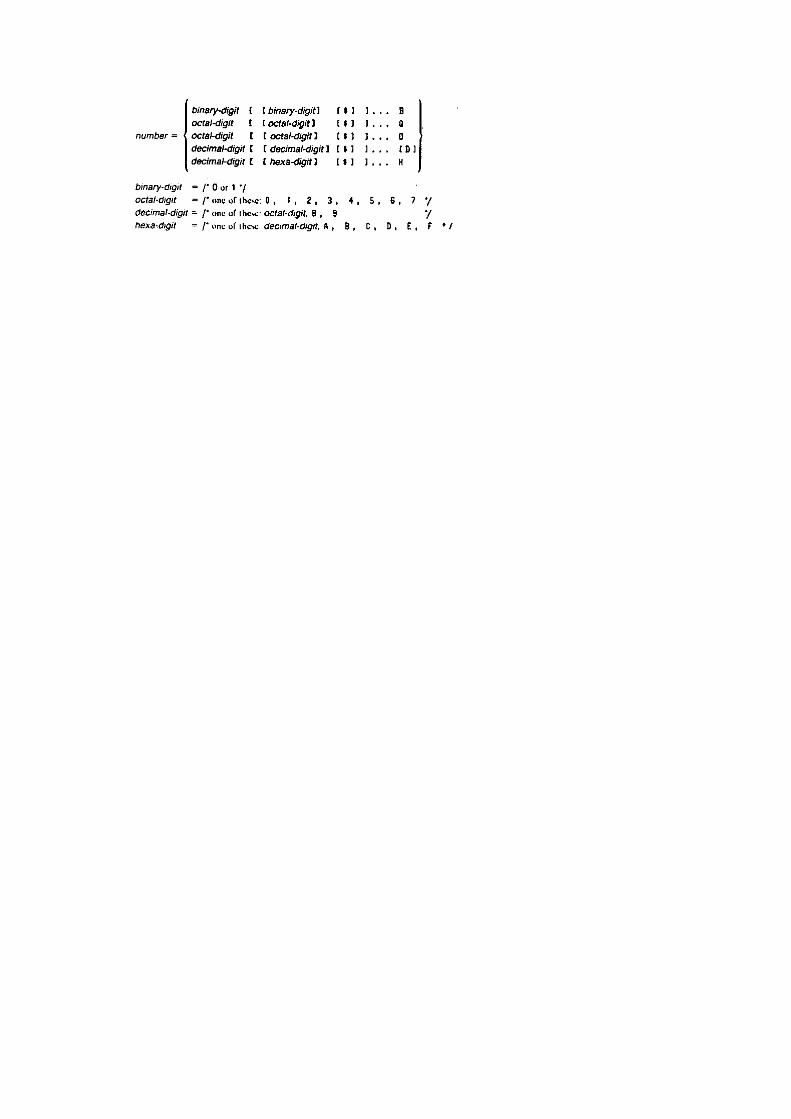

Program Constraints BCertain fixed size tables within the compiler constrain various features of a user program to certainmaximums. These limits are summarized below:
Nesting of LITERALLY invocations 5Nesting of INCLUDE controls 5Nesting of blocks 16Number of elements in a factored list 32Number of characters in an input line 122Length of a string constant 254Number of cases in a DO CASE block 84Number of EXTERNAL items 255Number of non-EXTERNAL procedures in a module 254Number of (10-character) names in a module appr. 700

PL/M-51 Reserved Words CThese are the reserved words of PL/M-51. They may not be used as identifiers.
ADDRESS INDIRECTLY_CALLABLEAND INTERRUPTAT LABELAUXILIARY LITERALLYBASED MAINBIT MINUSBY MODBYTE NOTCALL ORCASE PLUSCONSTANT PROCEDUREDECLARE PUBLICDISABLE REGISTERDO RETURNELSE STRUCTUREENABLE THENEND TOEXTERNAL USINGGO WHILEGOTO WORDIDATA XORIF

Predeclared Identifiers DThese are the identifiers for the built-in procedures. If one of these identifiers is declared in a DECLAREstatement, the corresponding built-in procedure becomes unavailable within the scope of the declaration.
BOOLEAN ROLDEC RORDOUBLE SCLEXPAND SCRHIGH SHLLAST SHRLENGTH SIZELOW TESTCLEARPROPAGATE TIME

Differences between PL/M-80 Eand PL/M-51
Most PL/M-80 programs cannot be used as PL/M-5l programs unless they are modified. Approximatelyninety-five percent of the statements in a PL/M-80 program need no modifications whatsoever. The mainchanges to keep in mind are memory, I/O, interrupts, bits, overlaying variables, and words all of which arediscussed in the following paragraphs.
E.1 Memory
The biggest difference between the 8080/8085 and the 8051 (and hence between their PL/Ms) is the waymemory is organized. The 8080 has a single memory, from byte 0 to byte 65535. Therefore, a PL/M-80variable has a type and an address nothing more.
The 8051 has more than one memory: it has on-chip RAM. off-chip RAM, and ROM, and if you specify aBYTE at address 17. it can still be in one of 3 places (it is like specifying --140 main street’ withoutnaming the town: or phone number 555-1212 without an area code). Therefore, a PL/M-51 variable has atype, an address, and a suffix specifying the memory space it occupies. If you do not specify a suffix.NIAIN is assumed. If you want to use the PL/M-X0 DATA initialization (renamed to CONSTANT).CONSTANT is assumed. Thus, in an application without off- chip RAM (alias AUXILIARY). most non-BASED declarations get you the memory you want. But. BASED declarations are dangerous. For example.if you get the message ~3 defaulted based variables make sure these 3 declarations do what you want.
E.2 I/O
The 8051 has no I/O operations: all I/O is done using special-function registers, which are variables at on-chip RAM (or BIT) addresses 128-255. To read port 0 and copy it to port 1, write the following in ASMSI:
MOV P1,P0
PL/M-51 has no I/O operations either. It lets you declare the hardware registers you want to use (e.g..DECLARE PCON AT(87H) REGISTER). or the easier option $INCLUDE a file of such declarations:when available, this kind of file will be supplied for every member of the MCS-51 family.
Once the REGISTER variables are declared and if your PL/M-51 program wants to copy port 0 to port 1you can write P1 = P0.
E.3 Interrupts
8051 has 4 register-banks. PL/M-5l assumes that you will never let an interrupt procedure use the samebank as the procedure it interrupts; total chaos can result if you do. The USING attribute of a procedure, orthe $REGISTERBANK control, can be used to ensure that you never let an interrupt procedure use thesame bank as the procedure it interrupts. To avoid any problems, use one register-bank for non-interruptcode, one for low-priority interrupts, and one for high-priority interrupts.

E.4 Bits
In order to use the 8051’s Boolean processor, PL/M-51 has a BIT data type. BITs are 1 bit long, and can be1 (true) or 0 (false). The results of comparisons in PL/M-51 are of BIT type, rather than BYTE, as in PL/M-80. Automatic conversions to/from BITs do not occur; you must explicitly use the applicable built-hifunctions.
E.5 Overlaying Variables
Since MAIN and BIT memory is extremely scarce, the default setting of the $OPTIMIZE control lets thecompiler overlay the variables of any two different procedures or DO blocks if it is sure they both cannotbe active simultaneously (see $OPTIMIZE(2) in Chapter 14). Thus, you have to start thinking like anALGOL or Pascal programmer unless you have RAM to spare: the variables of a procedure or DO blockbecome undefined upon procedure exit.
E.6 Words
A minor point is the order of bytes within a word. In PL/M-5l, unlike PL/M-80, the first byte of a wordcontains its high-order byte. Thus, if a WORD variable has value 1234H, its first byte will be 12H and itssecond will be 34H. If you avoid overlaying BYTEs on top of WORDs, this should not affect yourprogram.

ASCII Codes FASCII
characterHEX PL/M-51
Character ?ASCII character HEX PL/M-51
character ?
NUL 00 no @ 40 YESSOH 01 no A 41 YESSTX 02 no B 42 YESETX 03 no C 43 YESEDT 04 no D 44 YESEND 05 no E 45 YESACK 06 no F 46 YESBEL 07 no G 47 YESBS 08 no H 48 YESHT 09 no I 49 YESLF 0A no J 4A YESVT 0B no K 4B YESFF 0C no L 4C YESCR 0D no M 4D YESSO 0E no N 4E YESSI 0F no O 4F YES
DLE 10 no P 50 YESDCI 11 no Q 51 YESDC2 12 no R 52 YESDC3 13 no S 53 YESDC4 14 no T 54 YESNAK 15 no U 55 YESSYN 16 no V 56 YESETB 17 no W 57 YESCAN 18 no X 58 YESEM 19 no Y 59 YESSUB 1A no Z 5A YESESC 1B no [ 5B NoFS 1C no \ 5C NoGS 1D no ] 5D NoRS 1E no ^ 5E NoUs 1F no _ 5F YES
Space 20 YES ` 60 No! 21 no a 61 YES“ 22 no b 62 YES# 23 no c 63 YES$ 24 YES d 64 YES% 25 no e 65 YES& 26 no f 66 YES, 27 YES g 67 YES( 28 YES h 68 YES) 29 YES I 69 YES* 2A YES j 6A YES+ 2B YES k 6B YES, 2C YES l 6C YES- 2D YES m 6D YES. 2E YES n 6E YES/ 2F YES o 6F YES0 30 YES p 70 YES1 31 YES q 71 YES2 32 YES r 72 YES3 33 YES s 73 YES4 34 YES t 74 YES5 35 YES u 75 YES6 36 YES v 76 YES7 37 YES w 77 YES8 38 YES x 78 YES9 39 YES y 79 YES: 3A YES z 7A YES; 3B YES { 7B No< 3C YES | 7C No= 3D YES } 7D No> 3E YES ~ 7E No? 3F no DEL 7F No

Interfacing PL/M-51 to ASM51 GThe segments and PUBLICs generated by the PL/M-51 compiler must have names. A user who writes onlyPL/M-51 code may ignore all of these names. A user who interfaces PL/M-51 with ASM51 must know thenaming conventions for PUBLICs.The naming conventions for PUBLICs are described in the following paragraphs.
G.1 Calling Sequence
If a procedure is called FOO, the entry-point for calls to it is called FOO - To pass parameters, twoPUBLICs are supplied: the starting addresses of two regions, one in DATA space and one in BIT space,where parameters have to be placed. These two addresses are named ?FOO?BYTE and ?FOO?BIT,respectively.
During the procedure call, parameters are placed in on-chip RAM starting at these addresses. BITparameters start at ?FOO?BIT, and BYTE parameters at ?FOO?BYTE. A WORD parameter is regarded astwo BYTE parameters, with its high-order byte coming first.
For example, consider a PL/M-51 procedure:
Q: PROCEDURE(BIT1,BYTE1,BIT2,WORD1) PUBLIC;
Its first BIT parameter will be put in ?Q?BIT. and its second in ?Q?BIT+1. in the BIT address space. Itsfirst BYTE parameter will be put in ?Q?BYTE. and its WORD parameter in ?Q?BYTE+1 (high-order byte)and ?Q?BYTE+2 (low-order byte). in MAIN memory. The procedure’s entry-point will be called Q.
To call this procedure from ASM51 code, we have to move its parameters to their proper destination. Thus,to simulate
CALL Q(1,72,0,747)
in ASM51, write
EXTRN CODE(Q)EXTRN BIT(?O?BIT)EXTRN DATA(?Q?BYTE)SETB ?Q?BITMOV ?Q?BYTE,#72CLR ‘ ?Q?BIT+ 1MOV ?Q?BYTE+1,#HIGH(747)MOV ?Q?BYTE+2,#LOW(747)CALL Q
To write an assembly-language procedure to do Q’s job. you have to write
PUBLIC QPUBLIC ?Q?BITPUBLIC ?Q?BYTEBITS SEGMENT BITBYTES SEGMENT DATAPROC SEGMENT CODERSEG BITS

?Q?BITBIT1: DBIT 1BIT2: DBIT 1
RSEG BYTES?Q?BYTE:BYTE1: DS 1WORD1: DS 2
RSEG PROCQ:. . .
The labels for BIT1, BIT2. BYTE1 and WORD1 are not strictly necessary, but they let us avoid somearithmetic. For example, it is easier to -write WORD1 than ?Q?BYTE+1.
G.2 Procedure Epilogue
To return from the procedure. the compiler inserts a RET instruction at any point a RETURN is to beexecuted (including the final END statement, which is an implied RETURN).
G.3 Value Returned from Typed Procedure
The result of a typed procedure is returned as shown in table G-l.
Table C-1. Typed Procedure Values
Procedure Type Result returned inByte A Register
WORD R6 and R7BIT C register ( the carry bit)

RunTime Interrupt Processing HH.1 General Information
An interrupt is initiated when the CPU receives a signal from some device (on-chip or off-chip).
Note that the CPU does not respond to this signal unless interrupts are enabled, and unless the specificinterrupt in question is also enabled. In PL/M-51, the user is responsible for enabling and disablinginterrupts, which is done by using the IE register and the ENABLE and DISABLE statements.
If the interrupt is enabled, the following actions take place:
1. The CPU completes any instruction currently in execution.2. The PC register is placed on the stack (occupying two bytes of stack storage).3. Interrupts whose priority is the same or lower than the one being serviced are disabled.4. The low-level interrupt handler (supplied by PLM51.LIB) saves the A,B, DPTR and PSW
registerson the stack, switches to the interrupt procedure’s register-bank, and then activates the interruptprocedure corresponding to the interrupt number.
5. When that procedure terminates, the stack is automatically restored to its state when the interruptwas received. A, B, DPTR and PSW are restored, and control returns to the point where it wasinterrupted.
The mechanism for this activation and restoration, the interrupt vector, is described below.
H.2 The Interrupt Vector
If the NOINTVECTOR control is not used, an interrupt vector entry is automatically generated by thecompiler for each interrupt procedure. Collectively, the interrupt vector entries form the interrupt vector. IfNOINTVECTOR is used, the programmer must supply the interrupt vector as explained in section H3.
The interrupt vector is an absolute chunk of code beginning at location 3. The n-th entry’ is at location8*n+3. and contains a jump to another (relocatable) chunk of code (referred to here as the low-levelinterrupt handler) that first saves A. B. DPTR and PSW, sets PSW to select the correct register-bank. andthen calls the procedure declared with the INTERRUPT n attribute. These two pieces of code come fromPLM51.LIB during RL51-time.
Figure H-1 is an example of the code used to implement the interrupt vector entry and the low-levelinterrupt handler for interrupt 2. ?PIV02 is the start address of the interrupt vector entry, ?PIP02 is the startaddress of the low-level interrupt handler. ?PIH02 is the start address of the user written interruptprocedure. ?PSW02 is the appropriate setting of the PSW for the interrupt procedure as implied by theUSING attribute used for that procedure.

MODULE ?PIV02: the interrupt vector entry
NAME ?PIV02PUBLIC ?PIV02EXTRN CODE(?P1P02)
CSEG AT 02 *8 +3
?PIV02:LJMP ?PIP02END
: ----- MODULE ?PIP02:: low level interrupt handler:
NAME ?PIP02PUBLIC ?PIP02EXTRN CODE (?PIH02),
NUMBER(?PSW02)
?PIP02S SEGMENT codeRSEG ?PIP02S
?PIP02:PUSH ACCPUSH BPUSH DPHPUSH DPLPUSH PSWMOV PSW,#?PSW02LCALL ?PIH02POP PSWPOP DPLPOP DPHPOP BPOP ACCRETIEND
Figure H-1. ASM51 Code for Interrupt Vector and CPU Status Stacking
H.3 Writing Low-Level Interrupt Handlers Separately
To achieve faster response by pushing less (if you are sure that B and DPTR do not have to be saved), youmay want to write the interrupt vector entry and the low-level interrupt handler yourself.
If you want to handle interrupts yourself, compile your PL/M-51 interrupt-service routine without giving itthe INTERRUPT attribute. Then, make it PUBLIC, call it, for example MY_HANDLER and make sure ithas the right register-bank (i.e., USING attribute, or $REGISTERBANK setting).

Now, assemble an ASM51 program to call your handler. Your ASMSI program must look like the one thatfollows.
EXTRN CODE (MY_HANDLER)
MY_HANDLER_S_BANK EQU 3 ; for instanceMY_HANDLER_S_INTERRUPT_NO EQU S ; for instance
CSEG AT(8 * MY_HANDLER_S_INTERRUPT_NO + 3) ; the correct vector ; address
LJMP MY_LOW_LEVEL_INTERRUPT_HANDLER
HANDLER SEGMENT CODE
RSEG HANDLERMY_LOW_LEVEL_INTERRUPT_HANDLER:
PUSH ACC; PUSH B, DPL and DPH were eliminated
PUSH PSWMOV PSW,#8*MY_HANDLER_S_BANKLCALL MY_HANDLERPOP PSW; POP DPH, DPL and B were eliminated
POP ACCRETIEND
H.4 Writing Interrupt Vectors Separately
The only code at the interrupt-vector address is an LJMP to the low-level interrupt handler supplied byPLM51.LIB. If you want to write your own vector and use the existing low-level handler, you have toknow that handler’s PUBLIC name. For interrupt number 0. this name is ?PIP00: for interrupt number 1.?PIP01: and so on.
Thus, to produce your own vector-entry for interrupt no.4. write
EXTRN CODE(?PIPO4)CSEG AT(4*8+3)LJMP ?PIPO4END
and assemble under ASM51.
The PL/M-51 interrupt handler must have the INTERRUPT attribute so the low-level interrupt handler willhave access to its entry-point. The interrupt handler must be compiled under $NOINTVECTOR.
H.5 PL/M-51 Errors Detected at RL51-Time
It is illegal to have two different procedures with the same INTERRUPT attribute. If you break this rule inone module, the compiler will detect it; but, if the two procedures are in different modules, RL51 will haveto detect the error. RL51 detects the error by complaining about a doubly-defined symbol with a name like?PIHO5. Similar RL51 error messages will appear if module-level code (‘main program” in Fortranparlance) appears in more than one module.

The Processor Descriptor Files IThe REGnn.DCL files, listed below, are supplied with the PL/M-51 compiler. Each file contains all theREGISTER declarations needed for the appropriate machine (e.g., REG51.DCL contains the declarationsfor the 8051 microcomputer). All registers below have the same name in the appropriate 8051 seriesmanual. $INCLUDEing it in your source file will ensure that you never have to declare a register.
If, in some module, you have no use for a register, you can delete its definition from this file.
NOTE
The compiler uses the ACC, B. PSW, DPL and DPH registers to accomplish various computations and tohold temporary results. Use of these registers in the user program, although permitted, may causeunpredictable results (e.g., PSW = OFFH is dangerous).
/* REGISTER DECLARATIONS FOR 8051 */
DECLARE REG LITERALLY 'REGISTER';
/********* BYTE REGISTERS ********/
DECLAREP0 BYTE AT(80H) REG,P1 BYTE AT(90H) REG,P2 BYTE AT(0A0H) REG,P3 BYTE AT(0B0H) REG,PSW BYTE AT(0D0H) REG,ACC BYTE AT(0E0H) REG,B BYTE AT(0F0H) REG,
SP BYTE AT(81H) REG, DPL BYTE AT(82H) REG, DPH BYTE AT(83H) REG, PCON BYTE AT(87H) REG, TCON BYTE AT(88H) REG, TMOD BYTE AT(89H) REG, TL0 BYTE AT(8AH) REG, TL1 BYTE AT(8BH) REG, TH0 BYTE AT(8CH) REG, TH1 BYTE AT(8DH) REG, IE BYTE AT(0A8H) REG, IP BYTE AT(0B8H) REG, SCON BYTE AT(98H) REG, SBUF BYTE AT(99H) REG;
/********* BIT REGISTERS ********/
/********* PSW BITS ********/DECLARE CY BIT AT(0D7H) REG, AC BIT AT(0D6H) REG, F0 BIT AT(0D5H) REG, RS1 BIT AT(0D4H) REG, RS0 BIT AT(0D3H) REG,

OV BIT AT(0D2H) REG, P BIT AT(0D0H) REG,
/********* TCON BITS ********/ TF1 BIT AT(8FH) REG, TR1 BIT AT(8EH) REG, TF0 BIT AT(8DH) REG, TR0 BIT AT(8CH) REG, IE1 BIT AT(8BH) REG, IT1 BIT AT(8AH) REG, IE0 BIT AT(89H) REG, IT0 BIT AT(88H) REG,
/********* IE BITS ********/ EA BIT AT(0AFH) REG, ES BIT AT(0ACH) REG, ET1 BIT AT(0ABH) REG, EX1 BIT AT(0AAH) REG, ET0 BIT AT(0A9H) REG, EX0 BIT AT(0A8H) REG,
/********* IP BITS ********/ PS BIT AT(0BCH) REG, PT1 BIT AT(0BBH) REG, PX1 BIT AT(0BAH) REG, PT0 BIT AT(0B9H) REG, PX0 BIT AT(0B8H) REG,
/********* P3 BITS ********/ RD BIT AT(0B7H) REG, WR BIT AT(0B6H) REG, T1 BIT AT(0B5H) REG, T0 BIT AT(0B4H) REG, INT1 BIT AT(0B3H) REG, INT0 BIT AT(0B2H) REG, TXD BIT AT(0B1H) REG, RXD BIT AT(0B0H) REG,
/********* P3 BITS ********/ P37 BIT AT(0B7H) REG, P36 BIT AT(0B6H) REG, P35 BIT AT(0B5H) REG, P34 BIT AT(0B4H) REG, P33 BIT AT(0B3H) REG, P32 BIT AT(0B2H) REG, P31 BIT AT(0B1H) REG, P30 BIT AT(0B0H) REG,
/********* SCON BITS ********/ SM0 BIT AT(9FH) REG, SM1 BIT AT(9EH) REG, SM2 BIT AT(9DH) REG, REN BIT AT(9CH) REG, TB8 BIT AT(9BH) REG, RB8 BIT AT(9AH) REG, TI BIT AT(99H) REG, RI BIT AT(98H) REG;

/* REGISTER DECLARATIONS FOR 8044 */
DECLARE REG LITERALLY 'REGISTER';
/********* BYTE REGISTERS ********/DECLARE P0 BYTE AT(80H) REG, P1 BYTE AT(90H) REG, P2 BYTE AT(0A0H) REG, P3 BYTE AT(0B0H) REG, PSW BYTE AT(0D0H) REG, ACC BYTE AT(0E0H) REG, B BYTE AT(0F0H) REG, SP BYTE AT(81H) REG, DPL BYTE AT(82H) REG, DPH BYTE AT(83H) REG, TCON BYTE AT(88H) REG, TMOD BYTE AT(89H) REG, TL0 BYTE AT(8AH) REG, TL1 BYTE AT(8BH) REG, TH0 BYTE AT(8CH) REG, TH1 BYTE AT(8DH) REG, IE BYTE AT(0A8H) REG, IP BYTE AT(0B8H) REG,
EINT BYTE AT(09EH) REG, EBUF BYTE AT(09FH) REG,
STS BYTE AT(0C8H) REG, SMD BYTE AT(0C9H) REG, RCB BYTE AT(0CAH) REG, RBL BYTE AT(0CBH) REG, RBS BYTE AT(0CCH) REG, RFL BYTE AT(0CDH) REG, STAD BYTE AT(0CEH) REG, DMACNT BYTE AT(0CFH) REG, NSNR BYTE AT(0D8H) REG, SIUST BYTE AT(0D9H) REG, TCB BYTE AT(0DAH) REG, TBL BYTE AT(0DBH) REG, TBS BYTE AT(0DCH) REG, FIFO1 BYTE AT(0DDH) REG, FIFO2 BYTE AT(0DEH) REG, FIFO3 BYTE AT(0DFH) REG;
/********* BIT REGISTERS ********/
/********* PSW BITS ********/DECLARE CY BIT AT(0D7H) REG, AC BIT AT(0D6H) REG, F0 BIT AT(0D5H) REG, RS1 BIT AT(0D4H) REG, RS0 BIT AT(0D3H) REG, OV BIT AT(0D2H) REG, P BIT AT(0D0H) REG,

/********* TCON BITS ********/ TF1 BIT AT(8FH) REG, TR1 BIT AT(8EH) REG, TF0 BIT AT(8DH) REG, TR0 BIT AT(8CH) REG, IE1 BIT AT(8BH) REG, IT1 BIT AT(8AH) REG, IE0 BIT AT(89H) REG, IT0 BIT AT(88H) REG,
/********* IE BITS ********/ EA BIT AT(0AFH) REG, ES BIT AT(0ACH) REG, ET1 BIT AT(0ABH) REG, EX1 BIT AT(0AAH) REG, ET0 BIT AT(0A9H) REG, EX0 BIT AT(0A8H) REG,
/********* IP BITS ********/ PS BIT AT(0BCH) REG, PT1 BIT AT(0BBH) REG, PX1 BIT AT(0BAH) REG, PT0 BIT AT(0B9H) REG, PX0 BIT AT(0B8H) REG,
/********* P3 BITS ********/ RD BIT AT(0B7H) REG, WR BIT AT(0B6H) REG, T1 BIT AT(0B5H) REG, T0 BIT AT(0B4H) REG, INT1 BIT AT(0B3H) REG, INT0 BIT AT(0B2H) REG, TXD BIT AT(0B1H) REG, RXD BIT AT(0B0H) REG,
/********* STS BITS ********/ TBF BIT AT(0CFH) REG, RBE BIT AT(0CEH) REG, RTS BIT AT(0CDH) REG, SI BIT AT(0CCH) REG, BOV BIT AT(0CBH) REG, OPB BIT AT(0CAH) REG, AM BIT AT(0C9H) REG, RBP BIT AT(0C8H) REG,
/********* NSNR BITS ********/ NS2 BIT AT(0DFH) REG, NS1 BIT AT(0DEH) REG, NS0 BIT AT(0DDH) REG, SES BIT AT(0DCH) REG, NR2 BIT AT(0DBH) REG, NR1 BIT AT(0DAH) REG, NR0 BIT AT(0D9H) REG, SER BIT AT(0D8H) REG;

/* REGISTER DECLARATIONS FOR 8052 */
DECLARE REG LITERALLY 'REGISTER';
/********* BYTE REGISTERS ********/DECLARE P0 BYTE AT(80H) REG, P1 BYTE AT(90H) REG, P2 BYTE AT(0A0H) REG, P3 BYTE AT(0B0H) REG, PSW BYTE AT(0D0H) REG, ACC BYTE AT(0E0H) REG, B BYTE AT(0F0H) REG, SP BYTE AT(81H) REG, DPL BYTE AT(82H) REG, DPH BYTE AT(83H) REG, PCON BYTE AT(87H) REG, TCON BYTE AT(88H) REG, TMOD BYTE AT(89H) REG, TL0 BYTE AT(8AH) REG, TL1 BYTE AT(8BH) REG, TH0 BYTE AT(8CH) REG, TH1 BYTE AT(8DH) REG, IE BYTE AT(0A8H) REG, IP BYTE AT(0B8H) REG, SCON BYTE AT(98H) REG, SBUF BYTE AT(99H) REG,
T2CON BYTE AT(0C8H) REG, RCAP2L BYTE AT(0CAH) REG, RCAP2H BYTE AT(0CBH) REG, TL2 BYTE AT(0CCH) REG, TH2 BYTE AT(0CDH) REG;
/********* BIT REGISTERS ********/
/********* PSW BITS ********/DECLARE CY BIT AT(0D7H) REG, AC BIT AT(0D6H) REG, F0 BIT AT(0D5H) REG, RS1 BIT AT(0D4H) REG, RS0 BIT AT(0D3H) REG, OV BIT AT(0D2H) REG, P BIT AT(0D0H) REG,
/********* TCON BITS ********/ TF1 BIT AT(8FH) REG, TR1 BIT AT(8EH) REG, TF0 BIT AT(8DH) REG, TR0 BIT AT(8CH) REG, IE1 BIT AT(8BH) REG, IT1 BIT AT(8AH) REG, IE0 BIT AT(89H) REG, IT0 BIT AT(88H) REG,

/********* IE BITS ********/ EA BIT AT(0AFH) REG, ET2 BIT AT(0ADH) REG, ES BIT AT(0ACH) REG, ET1 BIT AT(0ABH) REG, EX1 BIT AT(0AAH) REG, ET0 BIT AT(0A9H) REG, EX0 BIT AT(0A8H) REG,
/********* IP BITS ********/ PT2 BIT AT(0BDH) REG, PS BIT AT(0BCH) REG, PT1 BIT AT(0BBH) REG, PX1 BIT AT(0BAH) REG, PT0 BIT AT(0B9H) REG, PX0 BIT AT(0B8H) REG,
/********* P1 BITS ********/ T2EX BIT AT(091H) REG, T2 BIT AT(090H) REG,
/********* P3 BITS ********/ RD BIT AT(0B7H) REG, WR BIT AT(0B6H) REG, T1 BIT AT(0B5H) REG, T0 BIT AT(0B4H) REG, INT1 BIT AT(0B3H) REG, INT0 BIT AT(0B2H) REG, TXD BIT AT(0B1H) REG, RXD BIT AT(0B0H) REG,
/********* SCON BITS ********/ SM0 BIT AT(9FH) REG, SM1 BIT AT(9EH) REG, SM2 BIT AT(9DH) REG, REN BIT AT(9CH) REG, TB8 BIT AT(9BH) REG, RB8 BIT AT(9AH) REG, TI BIT AT(99H) REG, RI BIT AT(98H) REG,
/********* T2CON BITS ********/ TF2 BIT AT(0CFH) REG, EXF2 BIT AT(0CEH) REG, RCLK BIT AT(0CDH) REG, TCLK BIT AT(0CCH) REG, EXEN2 BIT AT(0CBH) REG, TR2 BIT AT(0CAH) REG, C_T2 BIT AT(0C9H) REG, CP_RL2 BIT AT(0C8H) REG;
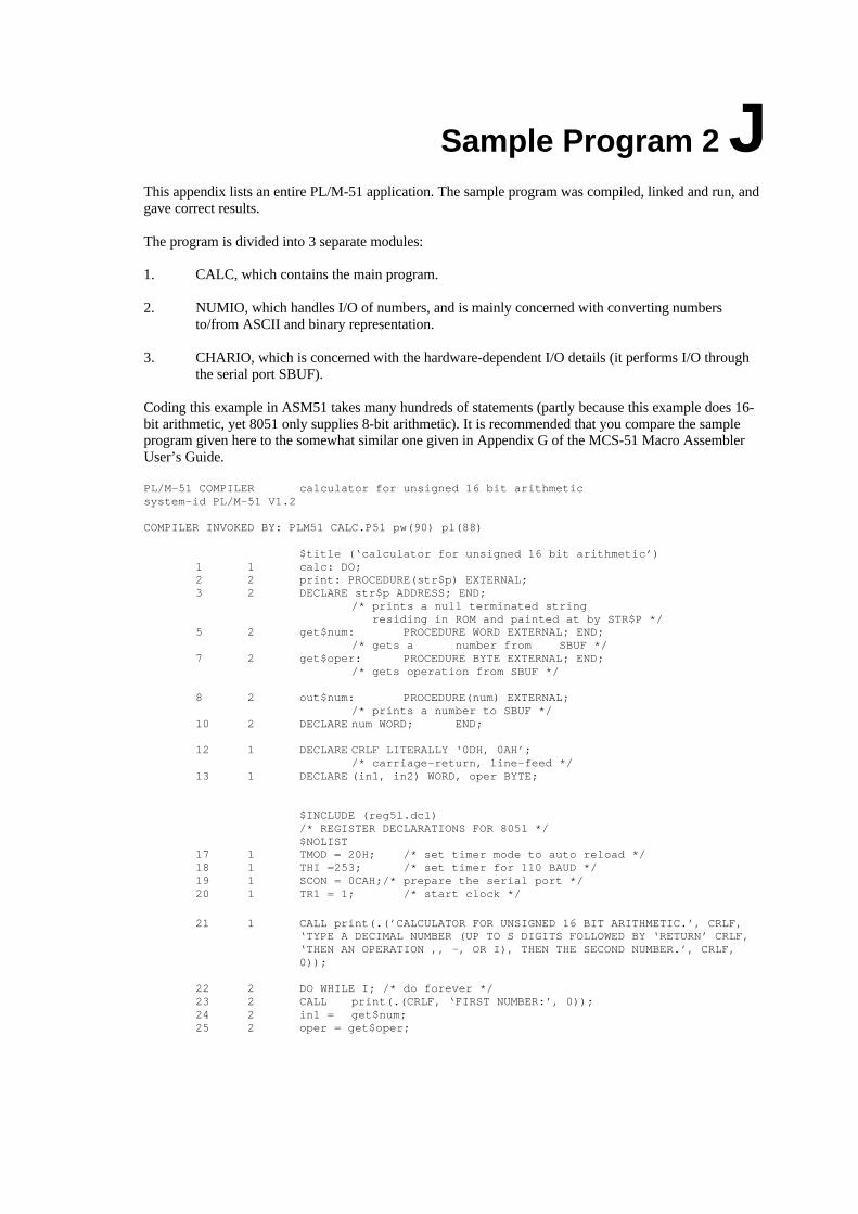
Sample Program 2 JThis appendix lists an entire PL/M-51 application. The sample program was compiled, linked and run, andgave correct results.
The program is divided into 3 separate modules:
1. CALC, which contains the main program.
2. NUMIO, which handles I/O of numbers, and is mainly concerned with converting numbersto/from ASCII and binary representation.
3. CHARIO, which is concerned with the hardware-dependent I/O details (it performs I/O throughthe serial port SBUF).
Coding this example in ASM51 takes many hundreds of statements (partly because this example does 16-bit arithmetic, yet 8051 only supplies 8-bit arithmetic). It is recommended that you compare the sampleprogram given here to the somewhat similar one given in Appendix G of the MCS-51 Macro AssemblerUser’s Guide.
PL/M-51 COMPILER calculator for unsigned 16 bit arithmeticsystem-id PL/M-51 V1.2
COMPILER INVOKED BY: PLM51 CALC.P51 pw(90) pl(88)
$title (‘calculator for unsigned 16 bit arithmetic’)1 1 calc: DO;2 2 print: PROCEDURE(str$p) EXTERNAL;3 2 DECLARE str$p ADDRESS; END;
/* prints a null terminated string residing in ROM and painted at by STR$P */
5 2 get$num: PROCEDURE WORD EXTERNAL; END;/* gets a number from SBUF */
7 2 get$oper: PROCEDURE BYTE EXTERNAL; END;/* gets operation from SBUF */
8 2 out$num: PROCEDURE(num) EXTERNAL; /* prints a number to SBUF */
10 2 DECLARE num WORD; END;
12 1 DECLARE CRLF LITERALLY ‘0DH, 0AH’; /* carriage-return, line-feed */
13 1 DECLARE (in1, in2) WORD, oper BYTE;
$INCLUDE (reg5l.dcl)/* REGISTER DECLARATIONS FOR 8051 */$NOLIST
17 1 TMOD = 20H; /* set timer mode to auto reload */18 1 THI =253; /* set timer for 110 BAUD */19 1 SCON = 0CAH;/* prepare the serial port */20 1 TR1 = 1; /* start clock */
21 1 CALL print(.(’CALCULATOR FOR UNSIGNED 16 BIT ARITHMETIC.’, CRLF, ‘TYPE A DECIMAL NUMBER (UP TO S DIGITS FOLLOWED BY ‘RETURN’ CRLF, ‘THEN AN OPERATION ,, -, OR I), THEN THE SECOND NUMBER.’, CRLF,
0));
22 2 DO WHILE I; /* do forever */23 2 CALL print(.(CRLF, ‘FIRST NUMBER:’, 0));24 2 in1 = get$num;25 2 oper = get$oper;

26 2 CALL print(.(’SECOND NUMBER: ‘, 0) );
27 2 in2 = get$num;29 3 DO CASE(oper);2B 3 /*0 : + */ CALL out$num(in1 + in2);30 3 /*1 : - */ CALL out$num(in1 - in2);31 3 /*2 : * */ CALL out$num(in1 * in2);
/*3 : / */32 3 IF in2 = 0
THEN CALL print(.(’ATTEMPT TO DIVIDE BY 0’, CRLF, 0);34 3 ELSE CALL out$num(in1 /in2);35 3 END; /* of DO CASE */36 2 END; /* of DO forever */37 1 END calc;
MODULE INFORMATION: ( STATIC + OVERLAYABLE )CODE SIZE = 00B5H 181DCONSTANT SIZE = 00E0H 224DDIRECT VARIABLE SIZE = 05H + 00H 5D + 0DINDIRECT VARIABLE SIZE = 00H + 00H 0D + 0DBIT SIZE = 00H + 00H 0D + 0DBIT-ADDRESSABLE SIZE = 00H + 00H 0D + 0DAUXILIARY VARIABLE SIZE = 0000H 0DMAXIMUM STACK SIZE = 0004H 4DREGISTER-BANK(S) USED: 0125 LINES READ0 PROGRAM ERROR(S)
END OF PL/M-51 COMPILATION
PL/M-51 I/O for numbers and operation NUMIO.p51
system-id PL/M-S1 V1.2
COMPILER INVOKED BY: PLM51 NUMIO.p51 pw(90)
$title (‘I/O for numbers and operation’)1 1 num$io: DO;2 2 print: PROCEDURE(str$p) EXTERNAL;3 2 DECLARE strip ADDRESS; END; /* print a null terminated
string residing in ROM and pointed at by STR$P */5 2 Get$char: PROCEDURE BYTE EXTERNAL; END; /* get char from SBUF and
send it */17 2 Put$char PROCEDURE(char) EXTERNAL; /* print a char to SBUF */8 2 DECLARE char BYTE; END;
10 1 DECLARE CR LITERALLY ‘ODH’;1l 1 DECLARE CRLF LITERALLY ‘ODH, OAH’;
12 2 get$num: PROCEDURE WORD PUBLIC; /* gets a number from SBUF */13 2 DECLARE num WORD,
I, char) BYTE;14 2 num, i = 0;15 2 Char = Get$char;
/* each loop iteration handles one input character */16 3 DO WHILE char<>CR AND 1<5;17 4 IF char < ‘0’ OR char > ‘9’ THEN DO; /* error */19 4 CALL print(.(CRLF, ‘NOT A DECIMAL DIGIT. RETYPE NUMBER:’,0));
20 4 num,I=0 /* re-initialize */

PL/M-5l COMPILER I/O for numbers and operation
21 4 END;22 4 ELSE DO; /‘add digit to number/23 4 num = num *10 + char -‘0’;24 4 i = i +1;25 4 END;26 3 char = Get$char;27 3 END;28 2 IF char <> CR /* possible only if input had over 5 digits */
THEN CALL print(.(’ FIRST 5 DIGITS USED’, 0) );30 2 CALL print(.(CRLF, 0) );31 2 RETURN(num)32 1 END get$num;
33 2 Get$oper: PROCEDURE BYTE PUBLIC; /* gets operation from SBUF */34 2 DECLARE (i, char) BYTE;3S 2 DECLARE op_code(4) BYTE CONSTANT(’+-*/’);36 3 DO WHILE 1; /*DO forever (until a legal operation is typed)*/37 3 CALL print(.(’OPERATION:‘, 0) );39 3 char = Get$char;39 3 CALL print(.(CRLF, 0) );40 4 DO I = 0 to 3; /*check if input char is an operation */41 4 IF char = op_code(i) THEN RETURN(i);43 4 END;
44 3 CALL print(.(’ERROR. PLEASE TYPE +, -, •, OR /’, CRLF, 0));45 3 END; /of DO forever/46 1 END get$oper;
47 2 out$num: procedure(num) PUBLIC; /*prints a number to SBUF*/49 2 DECLARE num WORD;49 2 DECLARE (I, j, digit) BYTE;50 2 DECLARE power_10 WORD,
powers_l0(6) WORD CONSTANT(10000,1000,100,10,1,0);51 2 CALL print (.(’RESULT 15:’, 0));52 2 I = 0;53 3 DO WHILE num < powers_10(i); /* skip printing leading zeroes */54 3 i = i +1;55 3 END;56 3 DO J = 1 to 3; /* loop prints all digits except last */57 3 pover_10 = powers_10(j);59 3 Digit = num / power_10;59 3 CALL Put$char(’0’ + digit);60 3 num = num — digit * power_10;61 3 END;62 2 CALL Put$char(’0’+ num); /* print last digit */63 2 CALL print(.(CRLF, 0) );64 1 END outSnum;65 I END num$io;
MODULE INFORMATION: ( STATIC + OVERLAYABLE )CODE SIZE 0169H 361DCONSTANT SIZE 0090H 144DDIRECT VARIABLE SIZE 00H+07H 0D+7DINDIRECT VARIABLE SIZE 00H+00H 0D+0DBIT SIZE 00H+00H 0D+0DBIT-ADDRESSABLE SIZE 00H+00H 0D+0DAUXILIARY VARIABLE SIZE 0100H 0DMAXIMUM STACK SIZE 0002H 2DREGISTER-BANK(S) USED: 070 LINES READ
END OF PLM/51 COMPILATION

PL/M-S1 COMPILER character I/O through SBUF
system-id PL/M-SI Vx.yCOMPILER INVOKED BY: PLMSI CHARIO.p51 pw(9O) p1(66)
$title (‘character I/O through SBUF’)
1 1 char$io: DO;SINCLUDE (reg5l.dcl)
/* REGISTER DECLARATIONS FOR 8051 */$NOLIST
5 2 Put$char: PROCEDURE(char) PUBLIC; /* print a char to SBUF */6 2 DECLARE char BYTE;7 3 DO WHILE NOT TI; /* wait till ready for output */9 3 END;9 2 TI = 1;10 2 sbuf = char;11 1 END Put$char;
12 2 Get$char: PROCEDURE BYTE PUBLIC; /* get char from SBUF and echo */13 2 DECLARE char BYTE;14 3 DO WHILE NOT RI; /* wait till there is input */IS 3 END;16 2 RI = 0;17 2 Char = sbuf;18 2 CALL Put$char(char );19 2 RETURN(char);20 1 END Get$char;
21 2 print: procedure(strip) PUBLIC;22 2 DECLARE str$p ADDRESS; /* print a null terminated
string residing in RON and pointed at by STR$P */23 2 DECLARE char BASED strip BYTE CONSTANT;24 3 DO WHILE char <>0; /* till null terminator */25 3 CALL Put$char(char);26 3 str$p = str$p +1;27 3 END;29 1 END print;
29 1 END char$io;
MODULE INFORMATION: (STATIC+OVERLAYABLE)CODE SIZE 0043H 67DCONSTANT SIZE 0000H 0DDIRECT VARIABLE SIZE 00H+03H 0D+3DINDIRECT VARIABLE SIZE 00H+00H 0D+0DBIT SIZE 00H+0OH 0D+0DBIT-ADDRESSABLE SIZE 00H+00H 0D+0DAUXILIARY VARIABLE SIZE 0000H 0DMAXIMUM STACK SIZE 0004H 4DREGISTER-BANK(S) USED: 0119 LINES READ
0 PROGRAM ERROR(S) END OF PL/M-51 COMPILATION

How to Generate Better Code KIf you write PL/M-51 the object-code produced will neither be as compact, nor as fast, as the best ASM51code you can write for the job. But, you have a good chance of exceeding most ASMSI programmers in theefficient use of on-chip RAM.
It is worth noting, though, that certain computations can require many instructions and execute very slowlyon the 8051, even in assembly-language. If X and Y are WORD variables, it takes only 3 keystrokes towrite X/Y in your program: but, the code to do this job can take 500 microseconds or so (at 12 MHz). Thefollowing paragraphs describe actions to avoid if time or space are critical.
WORD operations are always more expensive than BYTE operations. Do not use WORD variables ifBYTEs will do the job: and do as little arithmetic with them as you can. Remember that DECLARE A ...BASED B:” is legal even if B is a BYTE. as long as A has a MAIN or IDATA suffix.
“DECLARE X <type> CONSTANT( 17):” is much more expensive than “DECLARE X LITERALLY‘17’: ~‘. The former construct causes X to be fetched from ROM each time it is used (by one or twoMOVC instructions. with the attendant set-up overhead). The latter causes the value of X to appear in thecode as an immediate (e.g.. #17).
The code to handle AUXILIARY variables is expensive and slow. Try to put only rarely-accessed variablesin AUXILIARY.
Division of a BYTE variable by anything is fairly cheap. Division of a WORD variable, even by a BYTE,can be very slow, depending on the divisor, keep in mind that SHR can be much cheaper than division.
On the other hand, procedure CALLs (and function calls). with or without parameters, are fairly cheap:they are much faster and more compact than in PL/M-80. Thus, the benefits of using procedures (programsare easier to understand and maintain) are available without the overhead that is usually associated withthem.
K.1 RAM Space Efficiency
Since all members of the 8051 family have 4K bytes or more of ROM. efficiency in using ROM space isnot a critical issue. On-chip RAM is a different matter, however. All members of the 8051 family have only128-256 bytes of on-chip RAM. From this 128-256 bytes, the register banks and stack must be deducted.Keep in mind, too. that you lose an additional byte of the on-chip RAM that remains for each 8-bit variableyou use.
$OPTIMIZE(2) (the default) goes some way to help here. It makes one critical assumption: that, when yourcode exits a PROCEDURE or DO block, you no longer care about the values of items declared inside it.and that, if you ever re-enter it. you are ready to accept garbage in them (until you reinitialize them). If youare ready to live by these rules (which are those of Pascal and ADA. and also those referring to thevariables of REENTRANT procedures in PL/M-80 and PL/M.86). the $OPTIMIZE( 2) default will assumeit has permission to share the same piece of on-chip RAM between procedures that do not call each other,and thus, to make 128

bytes do the work of 200 or 300. The compiler is careful not to play this trick if two procedures call eachother: but, it assumes that all such possible calls appear in the module it compiles. See the $OPTIMIZEcontrol in Chapter 14.
Based upon the information given in the preceding paragraphs, it follows that global (module level)variables are more expensive than local variables because the former cannot be overlaid.

Valid PL/M-51 Statements LThis appendix contains ‘various types of valid PL/M-51 statements that may help you remember where thecommas, semicolons, etc., must appear.
X,Y,Z = 8 XOR Y * MAX(’??’ ,.Z);X= X+1;CALL FOO(BAZ.GORP,THUD);CALL STRUC . WORD MEMBER;CALL ZILCH;IF 1>2 THEN CALL FOR_HELP(.(’S.O.S ‘‘,O));
ELSE RETURN;
DECLARE (KING,DAVID) BIT MAIN, STR() BYTE CONSTANT(’JERUSALEM’);DECLARE EIGHT.BITS LITERALLY ‘BYTE’;DECLARE PCON BYTE AT(87H) REGISTER;DECLARE 0 WORD CONSTANT PUBLIC, QQ LABEL EXTERNAL;DECLARE S STRUCTURE(NAME(31) BYTE, AGE BYTE, SEX BYTE);
DECLARE T STRUCTURE(BIT_1, BIT_2) BIT) AT(22H);
DECLARE X WORD AUXILIARY, XX BASED X BYTE CONSTANT;DECLARE Y AT(.YY+I) BYTE IDATA;
DO I = 1 TO 7;END;
DO; END;
X: DO;END X;
DO CASE I;; /* case 0 – null statement */; /* case 1 */CALL I_IS_2;; /* case 3 */
END;
DO I=1 TO 77 BY 13;END;
GO TO END;X: PROCEDURE INDIRECTLY CALLABLE;X: PROCEDURE INTERRUPT 4 USING 1;
MAX: PROCEDURE(X,Y) BYTE; DECLARE (X,Y) BYTE;IF X>Y THEN RETURN X; ELSE RETURN Y;
END MAX;
ZILCH: PROCEDURE EXTERNAL; END ZILCH;RETURN Y;
RETURN;

Assembler Utility Library:UTIL51.LIB MThe assembler utility library, UTIL5l.LIB, contains a number of procedures useful for string manipulation.These have been coded in ASMSI and have been optimized for speed. Each procedure has a namedetermined by the memory types involved. The generic forms, however, are as follows:
MOVxyi (source, destination, count) - move stringRMVxxi (source, destination, count)
CMPxyi (source 1, source2, count) - compare strings
FNDBxi (source, target, count) - search string for elementFNDWxi (source, target, count)
SKPBxi (source, target, count) - search string for mismatchSKPWxi (source, target, count)
SETBxi (destination, newvalue, count) - set string elements to valueSETWxi (destination, newvalue, count)
M.1 Using UTIL51.LIB
Two things are required when using one or more of the procedures from UTIL51.LIB in a program module:
• The module’s object-code file must be linked with UTIL51.LIB.• Any UTIL51.LIB procedure used in the module must be declared as an EXTERNAL procedure
before it is called.
To link the assembler utility library with the module’s object-code file, use RL51. For example, if theobject-code file is called MYNIOD.OBJ, then the necessary linkage is performed by the following:
RL51 MYMOD.OBJ, UTIL51.LIB, PLM51.LIB [options]
Here, the PLM51.LIB support library is necessary as described in Chapter 13. The options are RL51controls described in the MCS-SI Utilities User’s Guide.
The EXTERNAL declarations needed for UTIL51.LIB are shown in M.3. These are contained in thedeclaration file UTIL51.DCL. For example, the MOV procedure for moving strings from on-chip RAM(DATA or IDATA) to external RAM (XDATA) has the following declaration:
MOVDX1 : PROCEDURE (from, target, count) EXTERNAL USING 1; DECLARE from BYTE, target WORD, count BYTE;
END;
The parameters of each UTIL51.LIB procedure have either BYTE or WORD (ADDRESS) values. To savespace, BYTEs are used wherever possible. For example, the from parameter of MOVDX1 is declared aBYTE because any address in on-chip RAM will be FFH or less. That is, a BYTE is sufficient to expressany address in the from address space. On the other hand, the target parameter of MOVDX1 requires aWORD declaration because the size of the address space (XDATA) is larger than FFH.

As noted in 10.5, PL/M-51 makes the following assumptions about interrupts: an interrupt procedure mustnever use the same register bank as the procedure it interrupts. It is recommended that one register bank beused for the main program, one for the high level interrupt, and one for the low level interrupt.
Because it is likely that UTIL51.LIB procedures will be used by both interrupt handlers and the mainprogram, three copies of each procedure are included in the library. Each copy differs only in the suffix ofits procedure name. For example, UTIL51.LIB contains the following three procedures: MOVDX0,MOVDX1, and MOVDX2. Each of the three procedures is identical, except that each should be declaredUSING a different register bank. Although it is not necessary, it is recommended that the suffix of eachprocedure matches the register bank used by the procedure. The simplest way to do this is to edit a copy ofUTIL51.DCL and replace each occurrence with the desired register bank number.
M.2 The UTIL51. LIB Procedures
The generic forms of the UTIL51.LIB procedures contain the following mnemonics:
x, y the address spaces of the source and target respectively, These can have the followingdesignations:
X xdata (AUXILARY)C constant (ROM)D data or idata (MAIN)
I the register bank used by the UTIL51.LIB procedure (0, 1, or 2).
The following are descriptions of the general forms of the UTIL51.LIB procedures.
MOVxyi
MOVxyi is an untyped procedure that copies a BYTE string from an x address space to a y address space.It is activated by
CALL MOVxyi (source, destination, count)
wheresource and destination are expressions that evaluate to address values in address spaces x and
y respectively.count is an expression with a BYTE or WORD value.I denotes the register bank (0. 1, or 2) used by the procedure.
The string elements are copied in ascending order. This will work in every situation except for those caseswhere all of the following are true:
• x and y are the same address space.• the destination address is higher than the source address.• both strings overlap.
In this particular case, elements in the overlap region get copied over before they have a chance to becopied. For this particular case, use RMV, which is the same as MOV, but copies elements in descendingorder.

RMVxxi
RMVxxi is an untyped procedure that copies a BYTE string from an x address space to the same addressspace. It is activated by
CALL RMVxxi (source, destination, count)
wheresource and destination are expressions that resolve to address values in x.count is an expression with BYTE or WORD value.I is the register bank (0, 1, or 2) used by the procedure.
RMV is the same as MOV except that elements are copied in descending order. This is needed for thespecial case of overlapping source and destination strings in the same address space having destinationaddress higher than the source address.
CMPxyi
CMPxyi is a WORD function that compares two BYTE strings. It is activated by a function reference withthe following form:
CMPxyi (source 1, source2, count)
wheresource1 and source2 are expressions that evaluate to address values in address
spaces x and y respectively.count is an expression with BYTE or WORD value.i is the register bank (0, 1, or 2) used by the procedure.
CMP compares two BYTE strings of length count whose locations start at source 1 and source2 in addressspaces x and y. CMP returns the index (position within the strings) of the first pair of elements found to beunequal. If both strings are equal, CMP returns the WORD value OFFFFH.
FNDBXI/FNDWxI
FNDBx, is a WORD function that searches a BYTE string to find an element that has a specified value. Itis activated by a function reference with the form:
FNDBxi (source, target, count)
where
source is an expression that evaluates to an address value in the address space x.target is an expression with BYTE or WORD value (if it is a WORD, the 8 high-order bits will
be dropped to produce a BYTE value).count is an expression with BYTE or WORD value.I is the register bank (0, 1, or 2) used by the procedure.
FNDB returns the index (position within the string) of the first occurrence of the BYTE value of target inthe source string. If no elements of the string match the BYTE value of target, the function returns0FFFFH.

FNDW is the same as FNDB except that it searches a WORD string instead of a BYTE string. If target hasa BYTE value, it is first extended by 8 high-order 0-bits to produce a WORD value.
SKPBxi/ SKPWxi
SKPB and SKPW are the converses of FNDB and FNDW (see above). Instead of searching for the firstelement of the source string that matches the target, SKPB and SKPW search for the first element that doesnot match the target. In every other respect, these functions operate the same as FNDB and FNDW.
SETBxi/ SETWxi
SETBxi is an untyped procedure that sets each element of a BYTE string to a single specified value. It isactivated by
CALL SETBxi (destination, newvalue, count)
Where
destination is an expression that evaluates to an address value in the x address space.
newvalue is an expression with a BYTE or WORD value (if it has a WORD value, the 8high-order bits are dropped to produce a BYTE value).
count is an expression with BYTE or WORD value.
i is the register bank (0, 1, or 2) used by the procedure.
SETB assigns the BYTE value of newvalue to each element of the BYTE string of count length beginningat destination.
SETW is the same as SETB except that it assigns a single WORD value to all the elements of a WORDstring. If newvalue is a BYTE, it is first extended by 8 high-order 0-bits to produce a WORD value.
M.3 UTIL51.LIB Procedure Declarations
The following is a list of the declarations for the procedures and functions included in UTIL51.LIB. Thesedeclarations are included in the file UTIL51.DCL. The file contains declarations for the utilities that useregister banks 0, 1, or 2. The user should select those needed, or if he desires to use procedures that useanother register bank, edit UTIL51.DCL to include the desired register bank number.
MOVDD1: PROCEDURE (from, target, count) EXTERNAL USING 1; /* MOVE DATA BYTES TO DATA */ DECLARE from BYTE, target BYTE, count BYTE;
END;
MOVXD1: PROCEDURE (from, target, count) EXTERNAL USING 1; /* MOVE XDATA BYTES TO DATA */
DECLARE from WORD, target BYTE, count BYTE;END;

MOVCD1: PROCEDURE (from, target, count) EXTERNAL USING 1; /* MOVE RON BYTES TO DATA */
DECLARE from WORD, target BYTE, count BYTE;END;
MOVDX1: PROCEDURE (from, target, count) EXTERNAL USING 1;/* MOVE DATA BYTES TO XDATA */
DECLARE from BYTE, target WORD, count BYTE;END;
MOVCX1: PROCEDURE (from, target, count) EXTERNAL USING 1; /* MOVE ROM BYTES TO XDATA */
DECLARE from WORD, target WORD, count WORD;END;
MOVXX1: PROCEDURE (from, target, count) EXTERNAL USING 1; /* MOVE XDATA BYTES TO XDATA */ DECLARE from WORD, target WORD, count WORD;
END;
RMVDD1: PROCEDURE (from, target, count) EXTERNAL USING 1; /* REVERSE MOVE DATA BYTES TO DATA */ DECLARE from BYTE, target BYTE, count BYTE;
END;
RMVXXI: PROCEDURE (from, target, count) EXTERNAL USING 1; /* REVERSE MOVE XDATA BYTES TO XDATA */
DECLARE from WORD, target WORD, count WORD;END;
CMPDDI: PROCEDURE (from, target, count) WORD EXTERNAL USING 1; /* COMPARE BYTES IN DATA TO BYTES IN DATA */ /* RETURN INDEX OR 0FFFFH */ DECLARE from BYTE, target BYTE, count BYTE;END;
CMPXDI: PROCEDURE (from, target, count) WORD EXTERNAL USING 1; /* COMPARE BYTES IN XDATA TO BYTES IN DATA */
/* RETURN INDEX OR 0FFFFH */ DECLARE from WORD, target BYTE, count BYTE;END;
CMPCDI: PROCEDURE (from, target, count) WORD EXTERNAL USING 1; /* COMPARE BYTES IN ROM TO BYTES IN DATA */ /* RETURN INDEX OR 0FFFFH */ DECLARE from WORD, target BYTE, count BYTE;END;
CMPCX1: PROCEDURE (from, target, count) WORD EXTERNAL USING 1; /* COMPARE BYTES IN ROM TO BYTES IN XDATA */ /* RETURN INDEX OR 0FFFFH */ DECLARE from WORD, target WORD, count WORD;END;
CMPCC1: PROCEDURE (from, target, count) WORD EXTERNAL USING 1; /* COMPARE BYTES IN ROM TO BYTES IN ROM */ /* RETURN INDEX OR 0FFFFH */ DECLARE from WORD, target WORD, count WORD;END;

CMPXX1: PROCEDURE (from , target, count) WORD EXTERNAL USING 1; /* COMPARE BYTES IN XDATA TO BYTES IN XDATA */ /* RETURN INDEX OR 0FFFFH */ DECLARE from WORD, target WORD, count WORD;END;
FNDBX1: PROCEDURE (from, target, count) WORD EXTERNAL USING 1; /* FIND target BYTE IN XDATA, RETURN INDEX OR 0FFFFH */ DECLARE from WORD, target BYTE, count WORD;END;
FNDBC1: PROCEDURE (from, target, count) WORD EXTERNAL USING 1; /* FIND target BYTE IN ROM, RETURN INDEX OR 0FFFFH */ DECLARE from WORD, target BYTE, count WORD;END;
FNDBD1: PROCEDURE (from, target, count) WORD EXTERNAL USING 1; /* FIND target BYTE IN DATA, RETURN INDEX OR 0FFFFH */
DECLARE from BYTE, target BYTE, count BYTE;END;
FNDWX1: PROCEDURE (from, target, count) WORD EXTERNAL USING 1; /* FIND target WORD IN XDATA, RETURN INDEX OR 0FFFFH */ DECLARE from WORD, target WORD, count WORD;END;
FNDWC1: PROCEDURE (from, target, count) WORD EXTERNAL USING 1; /* FIND target WORD IN ROM, RETURN INDEX OR 0FFFFH */ DECLARE from WORD, target WORD, count WORD;END;
FNDWDI: PROCEDURE (from, target, count) WORD EXTERNAL USING 1; /* FIND target WORD IN DATA, RETURN INDEX OR 0FFFFH */
DECLARE from BYTE, target WORD, count BYTE;END;
SKPBX1: PROCEDURE (from, target, count) WORD EXTERNAL USING 1; /* SKIP target BYTE IN XDATA, RETURN INDEX OR 0FFFFH */ DECLARE from WORD, target BYTE, count WORD;END;
SKPBC1: PROCEDURE (from, target, count) WORD EXTERNAL USING 1; /* SKIP target BYTE IN ROM, RETURN INDEX OR 0FFFFH */ DECLARE from WORD, target BYTE, count WORD;END;
SKPBD1: PROCEDURE (from, target, count) WORD EXTERNAL USING 1; /* SKIP target BYTE IN DATA, RETURN INDEX OR 0FFFFH */ DECLARE from BYTE, target BYTE, count BYTE;END;
SKPWX1: PROCEDURE (from, target, count) WORD EXTERNAL USING 1; /* SKIP target WORD IN XDATA, RETURN INDEX OR 0FFFFH */ DECLARE from WORD, target WORD, count WORD;END;
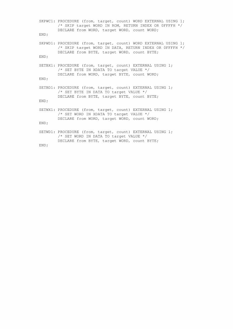
SKPWC1: PROCEDURE (from, target, count) WORD EXTERNAL USING 1; /* SKIP target WORD IN ROM, RETURN INDEX OR 0FFFFH */ DECLARE from WORD, target WORD, count WORD;END;
SKPWD1: PROCEDURE (from, target, count) WORD EXTERNAL USING 1; /* SKIP target WORD IN DATA, RETURN INDEX OR 0FFFFH */ DECLARE from BYTE, target WORD, count BYTE;END;
SETBX1: PROCEDURE (from, target, count) EXTERNAL USING 1; /* SET BYTE IN XDATA TO target VALUE */ DECLARE from WORD, target BYTE, count WORD;END;
SETBD1: PROCEDURE (from, target, count) EXTERNAL USING 1; /* SET BYTE IN DATA TO target VALUE */ DECLARE from BYTE, target BYTE, count BYTE;END;
SETWX1: PROCEDURE (from, target, count) EXTERNAL USING 1; /* SET WORD IN XDATA TO target VALUE */
DECLARE from WORD, target WORD, count WORD;END;
SETWD1: PROCEDURE (from, target, count) EXTERNAL USING 1; /* SET WORD IN DATA TO target VALUE */ DECLARE from BYTE, target WORD, count BYTE;END;