in the name of omnipotent - saba web pagesaba.kntu.ac.ir/eecd/people/dorosti/publications/dcs...
TRANSCRIPT

.
page ١
In the Name Of Omnipotent
K.N.Toosi University Of TechnologyControl Engineering Department
Masoud Dorosti
Study of DCS Technologyor
Distributed Control SystemsBased On
TXP Power Plant Control System
.
page ٢
Automation
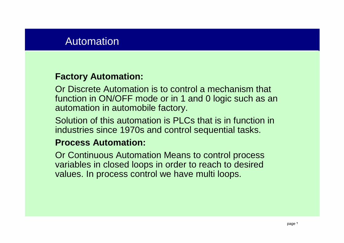
Factory Automation:Or Discrete Automation is to control a mechanism that function in ON/OFF mode or in 1 and 0 logic such as an automation in automobile factory.Solution of this automation is PLCs that is in function in industries since 1970s and control sequential tasks.Process Automation:Or Continuous Automation Means to control process variables in closed loops in order to reach to desired values. In process control we have multi loops.
.
page ٣
Introduction to Control Systems
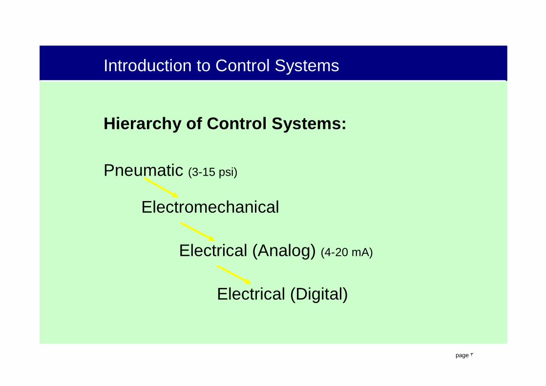
Hierarchy of Control Systems:
Pneumatic (3-15 psi)
Electromechanical
Electrical (Analog) (4-20 mA)
Electrical (Digital)

.
page ٤
Introduction to Control Systems
Chronological of control systems in large scale plants:
LCS in 1960s
CCS(DDC) in 1970s
DCS in 1980s
FCS in 1990s
LCS: Locally Control SystemCCS: Centralized Control SystemDDC: Direct Digital ControlDCS: Distributed Control SystemFCS: Field Control System

.
page ٥
THE HIERARCHICAL STRUCTURE OF DCS
Operating andmonitoring level
Field level
Processing level
OTOT OTOT OTOT
AGF
APAP
S5-AG
S5 E/ASIM-TSIM-FFUM-F
AP
FUM-B
Group control level
PUPU ES680ES680 DS670DS670
AP
APTAPF
SIM-B
OT/ETOT/ET
CTCT675CT675AP
OT/DTOT/DT
Individualcontrol level
Plant busPlant bus
Terminal busTerminal bus

.
page ٦
Field bus control system
What is the field?Field is a place that some processes take place in it and
instruments & actuators such as control elements & valves & pumps & motors & transducers & etc is placed on it.
So What is the field bus?Field bus in general is a network that join control elements
together and to higher control systems such as PLCs & DCS. In other words Field bus is a bus that go through the field and go toward instruments & actuators.
In new field bus we have smart elements. instruments, transducers and actuators have digital processor on itself to perform a two-way communication with other elements and / or control itself

.
page ٧
Field bus control system
What is Foundation field bus?Foundation field bus Is the name of a brand
such as Profibus and Devicenet.Foundation field bus and Profibus have the
same physical layer and work by rate of 31.25 kbps in the field

.
page ٨
Field bus control system
A typical Field bus has following layers:
• Physical layer: instead of 4-20 mA analog signal• Data link layer: communication control between different
devices• Application layer: data converting understandable box for
other systems• User layer: perform a functional control block
.
page ٩
GAS TURBINE FUNDAMENTALS
.
page ١٠
.
page ١١
.
page ١٢

.
page ١٣
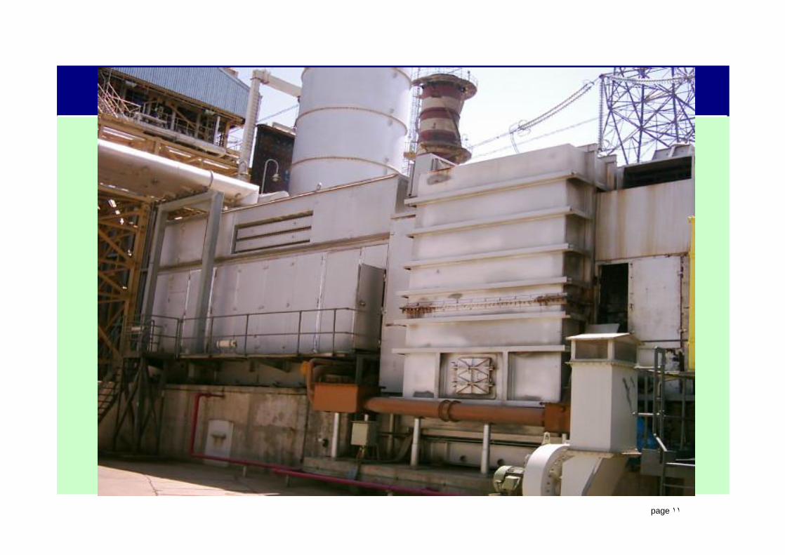
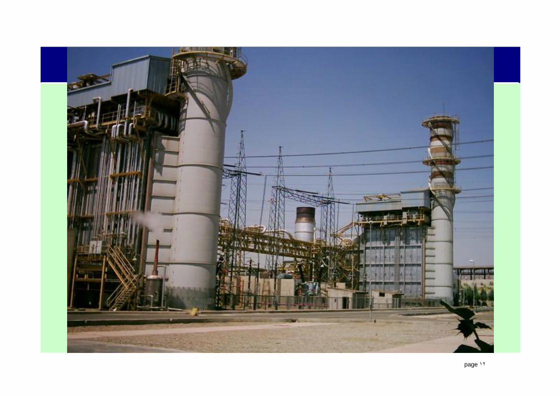
V94.3A COMBUSTION TURBINE
.
page ١٤
The control of a Combustion Turbine is a very precise and complicated task. Some of the items that need to be precisely controlled are:
• Active power, • Reactive power, • Power factor, • Voltage, • Frequency, • Speed, • Torque, • Ramp rates, and • Temperature.
GAS TURBINE CONTROL FUNDAMENTALS

.
page ١٥
PROCESS CONTROLA Gas Turbine is a process. The control of a Gas turbine is process control. We use different types of control schemes (Speed, Load)
Speed Loop ExampleSynchronization of Generator.
Goal - Match Frequency of Generator to Frequency of GridController changes speed of turbine to change the speed of the generator. Speed is Proportional to FrequencySpeed Change = Frequency Change
Position Loop ExampleFuel Control Valves. Change the position of a valve - Increase or Decrease Amount of FuelChange Flame Temp - Increases amount of Fuel - Flame will Become Hotter.Hotter Flame = Increase in Hot Gas Expansion Through TurbineIncrease in the Mass Flow through the Turbine.Increase in Either the speed or torque of the turbine.

.
page ١٦
The mass flow through the turbine is increasingThe controller in the SES (static excitation system) is increasing the Field Current to the generator,• Field Current Increase = Increase in the Magnetic Field, which prevents
the speed from increasing. • The increased field and increased torque cause an increase in the amount
of current flow through the generator stator• End Result = Increase in Load (Active Power).
PROCESS CONTROL
What prevents the speed/frequency from increasing when the generator is on load?

.
page ١٧
TURBINE CONTROL
Combustion turbines are controlled during all phases or modes ofits operation, from standstill through full load operations back to standstill. The 5 basic modes of control for a Combustion Turbine Generator are:
• SFC/SES Control• Speed Run Up• Speed Control• Load Control• Temperature Control

.
page ١٨
BASIC TURBINE CONTROL
SFC/SES Control
Speed Run-up Controller Load Controller
O%
Spe
ed
≅22
% S
peed
≅ 13
% S
peed
@ 7
0 %
Spe
ed
@ 1
00 %
Spe
ed
0 M
W@
MW
5 @ 5
0-60
% L
oad
≅ B
ase
Load
Tem
pera
ture
Bas
e Lo
ad
Tem
pera
ture
Lim
it
Fuel
ESV
Ope
nsM
ain
Flam
e O
n
Syn
chro
nize
r On
Spee
d Co
ntro
ller
Gen
erat
or B
reak
er C
lose
s
Initi
al M
W J
ump
Sw
itch
to P
rem
ixIG
Vs B
egin
Ope
ring T
empe
ratu
re
Con
trol
ler
.
page ١٩
SFC/SES CONTROL
Initial Start Up Phase of the Turbine. • Controls the Generator As a Motor to Start the Combustion
Turbine.
From Standstill the SFC (Start-up Frequency Converter) Controls Turbine Speed By Energizing the Stator of the Generator.
The SES (Static Excitation System) Provides a Field to the Rotor of the Generator.
The SFC/SES Will Be the Sole Controller in Operation Until Approximately 11 s-1 (660 RPM) [@22% Speed].
At this point, the Gas Turbine Controller will activate the Speed Run-up Controller.
.
page ٢٠
SPEED RUN-UP FUNCTION
6 At ≈ 6.6 s-1 (396 RPM) [13% speed] - NG ESV is opened and the turbine is fired
6 CT is not capable of accelerating on its own.
6 SFC/SES will continue motoring the generator to assist in the acceleration.
6 At ≈ 22% speed (11 s-1) [660 rpm], the Speed Run-up Function will be activated.
6 The Speed Run Up Function & SFC/SES Work Together
!The Speed Run-up Controller Controls the Diffusion Control Valve to Increase
the Amount of Fuel to Ramp Up to Nominal Speed
!As the Speed Run Up Function slowly increases its control of the turbine
(increases the amount of fuel), the SFC/SES Control slowly decreases its
control (amount of torque supplied by the generator).
6 At ≈ 70% Speed (≈ 35 s-1) [≈ 2100 RPM] the SFC and SES are turned off
6 CT will continue to accelerate on its own.

.
page ٢١
ActualSpeed
SpeedSetpoint 100%
Speed Run Upand Protection
FunctionLimiting Valve
ControllerEHC ElectroHydraulicConverter
6 Actual Turbine Speed Is Compared to a Speed Setpoint (100% or Nominal Speed).6 Output of the Speed Run-up Function Will Demand Greater Amounts of Fuel Within the Limits
of the Turbine Until the Actual Speed Approaches the Setpoint6 As Actual Speed Approaches Setpoint, the Output of the Speed Run up Function Decreases.6 Speed Run up Function Accelerates the Turbine to Nominal Speed!The Speed Run-up Controller Controls the Control Valves to Increase the Amount of Fuel
to Ramp Up to Nominal Speed!As the Speed Run Up Function Slowly Increases its control of the turbine (increases the
amount of fuel), the SFC/SES Control slowly decreases its control (amount of torque supplied by the generator).
6 Valve Controller Converts the Speed Run up Function Output to Analog Electric Signal. 6 EHC Electro Hydraulic Converter Converts the Electric Signal to a Hydraulic Signal
SPEED RUN-UP FUNCTION

.
page ٢٢
SPEED CONTROL
ActualSpeed
SpeedSetpoint 100%
Load/SpeedController Limiting Valve
ControllerEHC ElectroHydraulicConverter
SpeedSetpointControl
6 Controls the Amount of Fuel to the GT While Operating at or Near Synchronous Speed With the Generator Breaker Open.
6 Increases or Decreases Speed of the GT to Enable Synchronization of the Generator to the Grid.
6 The Gas Turbine Controller;!Activates the Speed/Load Controller in the Speed Control Mode for Synchronization,!Deactivates the Speed Run-up Controller,!Activates the Static Excitation System (SES) again
6 Synchronizing Unit Provides the Speed Setpoint Based on the Frequency of the Grid. !Speed can be Adjusted from 95% to 103%,
6 When Synchronizing Unit closes the Gen Breaker; !Gas Turbine Controller switches from Speed Control to Load Control!Load Controller Setpoint Output is set to 5 MW!Prevents Exhaust Gas Temperature Decrease!Reduces Thermal Stress of the Turbine

.
page ٢٣
LOAD CONTROL
The Load Control Mode Adjusts the Generated Load Based On the Load Setpoint and Other Conditions. Under Load Control, the SES Controller is Used to Generate and Change Load.
Load Control is more complicated than Speed Run-up or Speed Control.
At Any Time the Gas Turbine Controller Can Switch From Load Control to Speed Control or Temperature Control if Certain Conditions Occur.
Many Turbine Protection Functions Are Designed into the Gas Turbine Controller. They Can Prevent the Generator Load from Reaching the Load Setpoint.

.
page ٢٤
LOAD CONTROL
ActualLoad
Load/SpeedController
Limiting ValveController
EHC ElectroHydraulicConverter
Corrected OutletTemperature
Control
TemperatureSetpointControl
Base/PeakLoad Select
Fast/SlowGradient Select
Gradient
SetpointAdjuster
GeneratorLoad Limit
Manual LoadSetpoint
LoadSetpointControl
FrequencyInfluence
5 MW
Humming/AccelerationDetection
CorrectedOutlet
Temperature100 MW
Humming 1 =-6 MW
Humming 2 =-15 MW
Norm = 13 MW/minFast = 13 MW/minSlow= 7 MW/Min
13 MW/min
5, 18, 31, etc ~ 7 minto 100 MW
.
page ٢٥
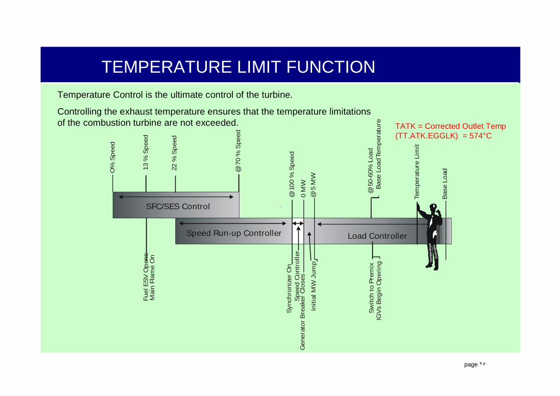
TEMPERATURE LIMIT FUNCTION
TATK = Corrected Outlet Temp(TT.ATK.EGGLK) = 574°C
Temperature Control is the ultimate control of the turbine.
Controlling the exhaust temperature ensures that the temperature limitations of the combustion turbine are not exceeded.
SFC/SES Control
Speed Run-up Controller Load Controller
O%
Spe
ed
≅22
% S
peed
≅ 13
% S
peed
@ 7
0 %
Spe
ed
@ 1
00 %
Spe
ed
0 M
W@
MW
5 @ 5
0-60
% L
oad
≅ B
ase
Load
Tem
pera
ture
Bas
e Lo
ad
Tem
pera
ture
Lim
it
Fuel
ESV
Op
ens
Mai
n Fl
ame
On
Syn
chro
nize
r On
Spe
ed C
ontr
olle
rG
ener
ator
Bre
aker
Clo
ses
Initi
al M
W J
ump
Sw
itch
to P
rem
ixIG
Vs
Beg
in O
peri
ng
Tem
pera
ture
Con
trol
ler

.
page ٢٦
FREQUENCY INFLUENCE
Allow a certain amount of fluctuation before attempting to correct the speed (frequency) of the combustion turbine.
Two different frequency functions are associated with combustion turbine control,
Frequency Limit FunctionAllows the speed of the generator to droop a total of +3/-5% (+90/-150 RPM) to stay synchronized. If the speed droop exceeds the limit, the generator breaker will open. The Frequency Limit Function is always active and cannot be disabled for normal operations.
Primary Frequency Influence FunctionWhen activated, will only allow the frequency to fluctuate 0.05Hz (3 RPM) before attempting to make a correction. This is a much tighter control of the frequency. Allows the Gas Turbine Controller to adjust the power output to compensate for the slightest frequency change; the maximum power output adjustment is limited to +/-75 MW from the setpoint. The generator breaker will open if this limit is exceeded.
.
page ٢٧
TXP CONTROL
The actual tasks of starting, stopping, controlling, monitoring,and protecting the turbine are controlled by the TXP AS620.
It would be impossible for anyone to operate the Combustion Turbine Generator by hand, there are way too many task that have to be carried out.

.
page ٢٨
SUB LOOP CONTROLLER “SLC”
• Turn Off Turning Gear• Turn On Lube Oil Pumps• Test Emergency DC Lube Oil Pump• Turn On Lift Oil Pump• Turn On Lube Oil Tank Vent Fan• Turn on the Hydraulic pumps• Open Inlet Air Damper• Open Blow Off Valves• Turn On SFC• Adjust Speed• Turn On Igniters
• Open Fuel Gas ESV• Adjust Fuel Gas Control Valve• Turn Off Lift Oil Pump• Turn Off SFC• Adjust Fuel Gas Control Valve• Close Blow Off Valves• Turn On SES• Adjust Voltage & Fuel Gas Control Valve• Turn On Synchronizer• Adjust Voltage & Fuel Gas Control Valve• Close Breaker• Adjust Load & Fuel Gas Control Valve
Sub Loop Controllers• Can be turned On or Off• When turned On,?Runs in a continues loop.?Constantly checking the status of a device or function.? If that status requires a specific action or task to be accomplished, the Sub Loop
Controller will carry out that action and continue monitoring the status for a change.Several Sub Loop Controllers are used in Combustion Turbine:

.
page ٢٩
Sends out a sequence of commands to devices and functions to perform a specific task, and waits to see if that task was accomplished in the required time.
• If not accomplished in the required time, the SGC MAY stop the whole process and begin the Shut Down Sequence.
• If accomplished, the SGC will proceed to the next sequence step to send out more commands.
Organized in steps, each step issues specific commands. A single step can issue one or more (and sometimes none) commands. Within that same step, there are tasks or statuses that the SGC needs to verify have been accomplished before proceeding to the next step, these are called permissives.
Typically, steps 1 through 50 are used for a Start Up Sequence, and steps 51 through 100 are used for a Shut Down Sequence.
SUB GROUP CONTROLLER “SGC”
.
page ٣٠
Sub Group Controllers are part of the AS620. Several Sub Group Controllers are used to control the Combustion Turbine:
• SGC Gas Turbine• SGC Lube & Lift Oil System• SGC Natural Gas• SGC Fuel Oil• etc.
SUB GROUP CONTROLLER “SGC”

.
page ٣١
SGC STEP SEQUENCE EXAMPLESTEP 56WT = 2s
&
MKC01DE111VAR = 0 BALANCE
XS56ON
MBJ01DE103XS56SFC CMD OFF
2s/30s
S56
BAC01GS001GEN CB
XS57CMD OPEN
0s/5s
S57
≥1
MKC01DE307VAR=0
XG33VALID
MKY01EU010GENERATOR
ZV02N ON LD
CB MKC01DE111CMD ON
CB MBJO1DE1013CMB OFF

.
page ٣٢
GAS TURBINE INSTRUMENTATION
.
page ٣٣
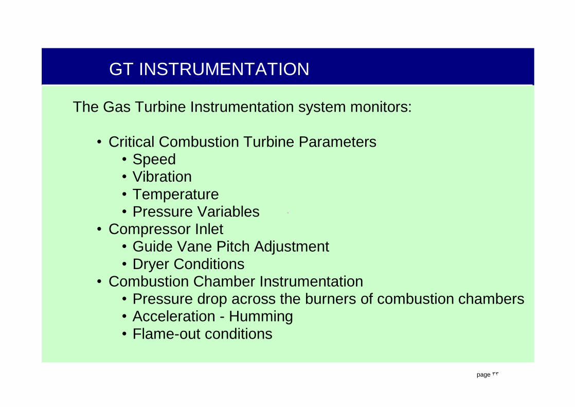
GT INSTRUMENTATION
The Gas Turbine Instrumentation system monitors:
• Critical Combustion Turbine Parameters• Speed• Vibration• Temperature• Pressure Variables
• Compressor Inlet• Guide Vane Pitch Adjustment• Dryer Conditions
• Combustion Chamber Instrumentation• Pressure drop across the burners of combustion chambers• Acceleration - Humming• Flame-out conditions

.
page ٣٤
GT INSTRUMENTATION
• The combustion turbine instrumentation system can be divided into the following tasks:
• Combustion Turbine Speed Measurement • Combustion Turbine Casing Vibration Measurement • Combustion Turbine Shaft Vibration Measurement • Bearing Temperature Measurement • Compressor Inlet Guide Vane (IGV) Pitch Adjustment • Compressor Inlet Temperature Measurement • Compressor Inlet Pressure Measurement • Compressor Outlet Pressure and Temperature Measurement • Turbine Outlet Temperature Measurement • Combustion Turbine Intake Air Drying

.
page ٣٥
GT INSTRUMENTATION
C o m b u s t io nC h a m b e r C o n t r o l
C o m p . O u t le tP r e s s . a n d T e m p .
T u r b i n e O u tl e tT e m p .
C a s i n g V i b r a t io n
B e a r in g T e m p .
S h a f t V ib r a t io n
C o m p . I n le t T e m p .
C o m p . IG VA c t u a to r
B e a r i n g T e m p .
C a s in g V i b r a t i o na t io n V i b r a t io n
G T S p e e d
C o m p . I n le t P r e s s .
S h a f t V i b r a t io n
A i r D r y in g
.
page ٣٦
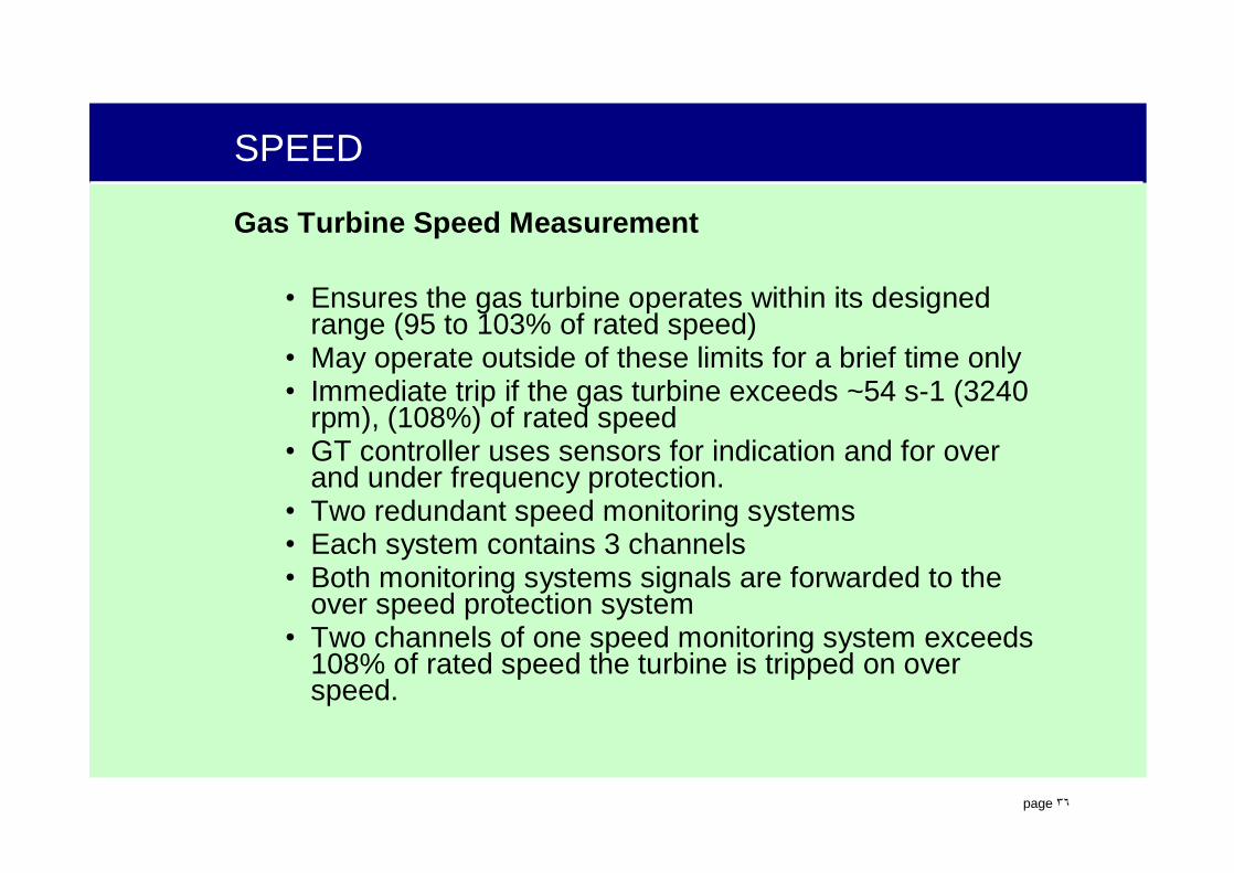
SPEED
Gas Turbine Speed Measurement
• Ensures the gas turbine operates within its designed range (95 to 103% of rated speed)
• May operate outside of these limits for a brief time only• Immediate trip if the gas turbine exceeds ~54 s-1 (3240
rpm), (108%) of rated speed• GT controller uses sensors for indication and for over
and under frequency protection.• Two redundant speed monitoring systems• Each system contains 3 channels• Both monitoring systems signals are forwarded to the
over speed protection system• Two channels of one speed monitoring system exceeds
108% of rated speed the turbine is tripped on over speed.

.
page ٣٧
SPEED
• The gas turbine CONTROLLER receives signals from ONEspeed monitoring system which receives signals from their speed sensors, MBA10CS101-103. This speed monitoring signal is used for the operation and control of the gas turbine. With the generator loaded (or not) the gas turbine will trip on over-under frequency if speed exceeds specific values for an extended period of time.
• If any 2 channels within a single speed monitoring system do not function properly, the gas turbine will immediately trip. If any 2 of the 3 channels of either set of signals to protection system do not function properly, the over speed protection system will trip. If at least 2 out of 3 speed signals from one of the speed monitoring systems indicate that the speed exceeds about 3,240rpm, the gas turbine will trip.

.
page ٣٨
SPEED
1. Speed Transmitter (MBA10CS101)2. Speed Transmitter (MBA10CS104)3. Speed Transmitter (MBA10CS102)4. Speed Transmitter (MBA10CS105)5. Speed Transmitter (MBA10CS103)6. Speed Transmitter (MBA10CS106)7. Intermediate Shaft8. Compressor Bearing9. Plug Connector10. Lower Bearing Seal
a. Groove in Intermediate Shaftb. Gap Between Shaft and Sensor
MBD12CY111 MBD12CY112
.
page ٣٩
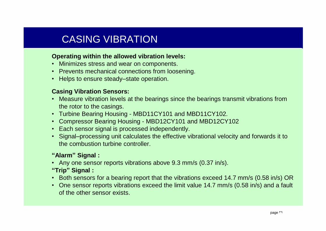
CASING VIBRATIONOperating within the allowed vibration levels:• Minimizes stress and wear on components. • Prevents mechanical connections from loosening.• Helps to ensure steady–state operation.
Casing Vibration Sensors:• Measure vibration levels at the bearings since the bearings transmit vibrations from
the rotor to the casings. • Turbine Bearing Housing - MBD11CY101 and MBD11CY102.• Compressor Bearing Housing - MBD12CY101 and MBD12CY102• Each sensor signal is processed independently.• Signal–processing unit calculates the effective vibrational velocity and forwards it to
the combustion turbine controller.
“Alarm” Signal :• Any one sensor reports vibrations above 9.3 mm/s (0.37 in/s). “Trip” Signal :• Both sensors for a bearing report that the vibrations exceed 14.7 mm/s (0.58 in/s) OR• One sensor reports vibrations exceed the limit value 14.7 mm/s (0.58 in/s) and a fault
of the other sensor exists.

.
page ٤٠
CASING VIBRATION
CT Startup is NOT allowed if a Vibration Measuring Fault exists.
Sensor Calibration Condition must be checked occasionally:• During Normal Operation - Turn the “CAL” key lock switch to
Cal - Checks the sensor and circuit condition.• DO NOT Check during Startup, Shutdown, or Large Load
Changes• Sensor is removed from Circuit and “CAL ON” alarm is
issued.
“CAN FLT” or “FAULT”• Signals from sensors of same bearing deviate by more than
1.0 mm/s for > 3 seconds.• Processor Module recognizes a disturbance of the sensor
signal• Sensor Signal is Above or Below it’s Specified Range.

.
page ٤١
CT CASING VIBRATION MEASUREMENT
MBD11CY112
MBD11CY111
MBD11CT101MBD11CT102
MBD11CY102MBD11CY101
MBD12CY101MBD12CY102
CompressorCasing Split
Compressor casing vibration
Turbine casing vibration
.
page ٤٢
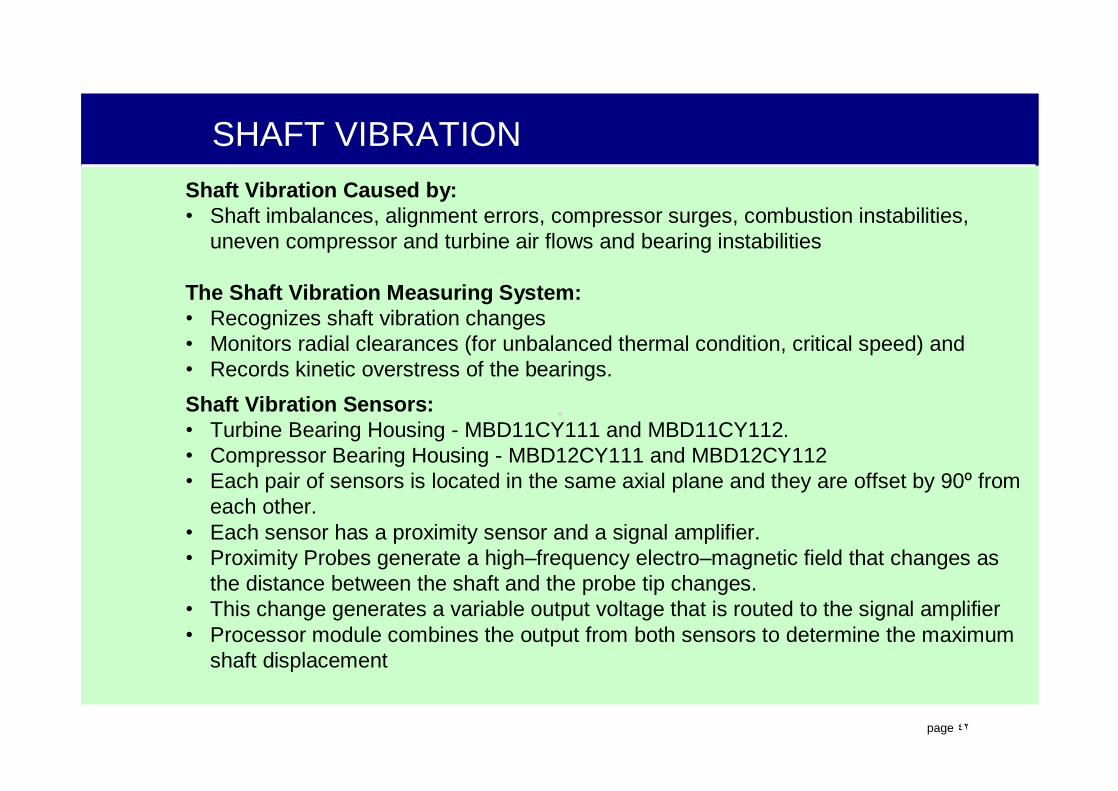
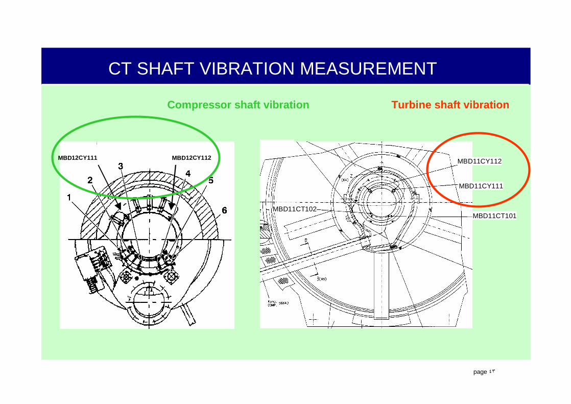
SHAFT VIBRATIONShaft Vibration Caused by:• Shaft imbalances, alignment errors, compressor surges, combustion instabilities,
uneven compressor and turbine air flows and bearing instabilities
The Shaft Vibration Measuring System:• Recognizes shaft vibration changes• Monitors radial clearances (for unbalanced thermal condition, critical speed) and • Records kinetic overstress of the bearings.Shaft Vibration Sensors:• Turbine Bearing Housing - MBD11CY111 and MBD11CY112.• Compressor Bearing Housing - MBD12CY111 and MBD12CY112• Each pair of sensors is located in the same axial plane and they are offset by 90º from
each other. • Each sensor has a proximity sensor and a signal amplifier.• Proximity Probes generate a high–frequency electro–magnetic field that changes as
the distance between the shaft and the probe tip changes.• This change generates a variable output voltage that is routed to the signal amplifier• Processor module combines the output from both sensors to determine the maximum
shaft displacement
.
page ٤٣
CT SHAFT VIBRATION MEASUREMENT
MBD11CY112
MBD11CY111
MBD11CT101MBD11CT102
Compressor shaft vibration Turbine shaft vibration
MBD12CY111 MBD12CY112

.
page ٤٤
GT BRG VIB/TEMP PRT
.
page ٤٥
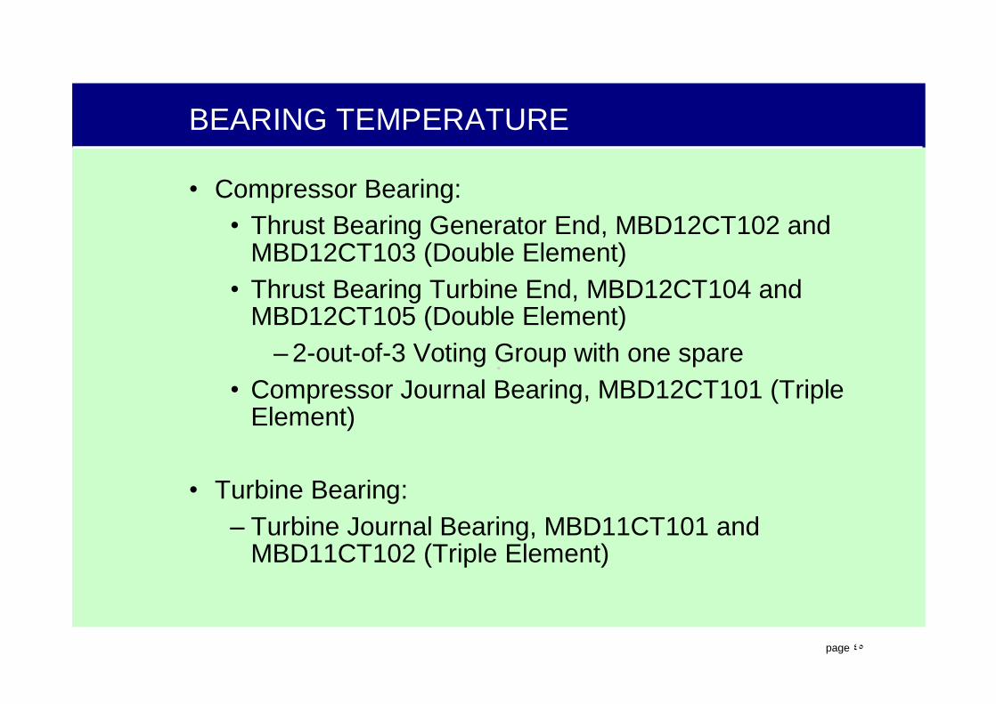
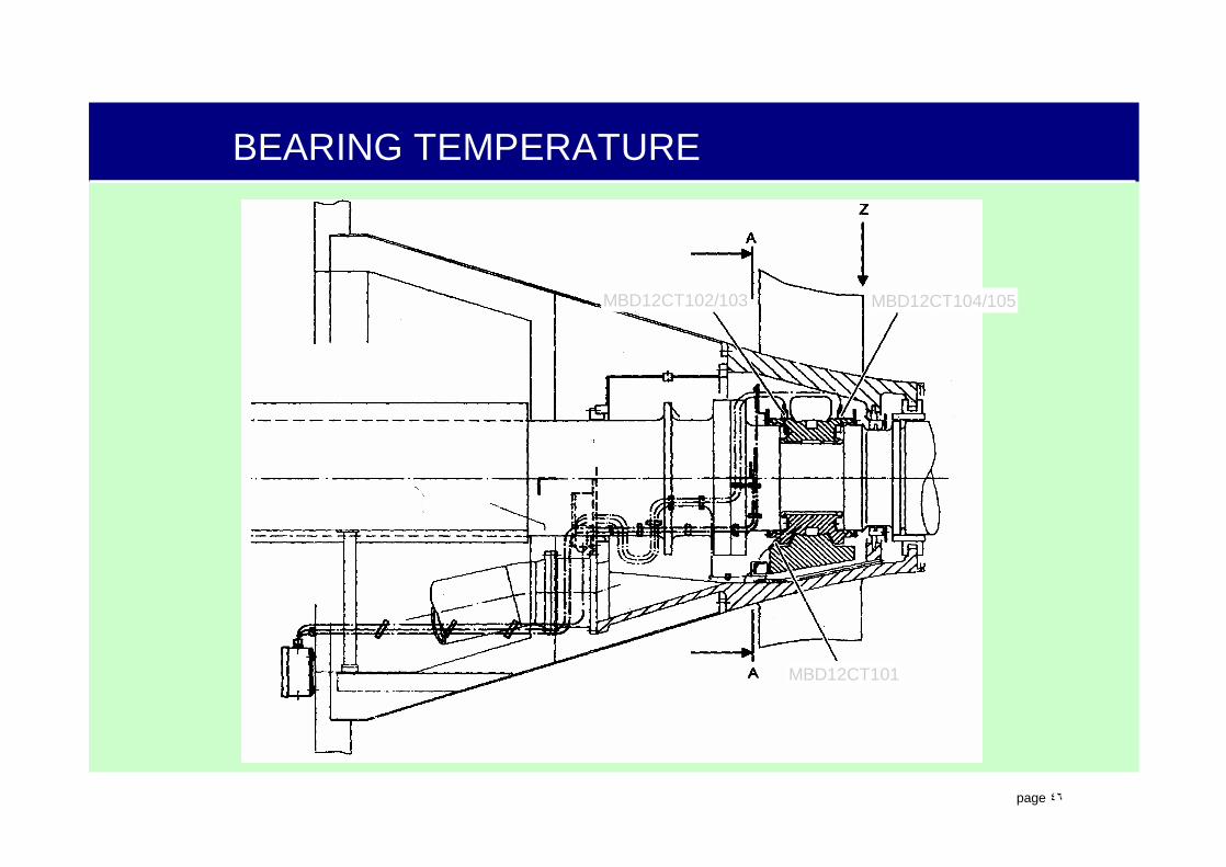
BEARING TEMPERATURE
• Compressor Bearing:• Thrust Bearing Generator End, MBD12CT102 and
MBD12CT103 (Double Element)• Thrust Bearing Turbine End, MBD12CT104 and
MBD12CT105 (Double Element)–2-out-of-3 Voting Group with one spare
• Compressor Journal Bearing, MBD12CT101 (Triple Element)
• Turbine Bearing:– Turbine Journal Bearing, MBD11CT101 and
MBD11CT102 (Triple Element)
.
page ٤٦
BEARING TEMPERATURE
MBD12CT101
MBD12CT102/103 MBD12CT104/105

.
page ٤٧
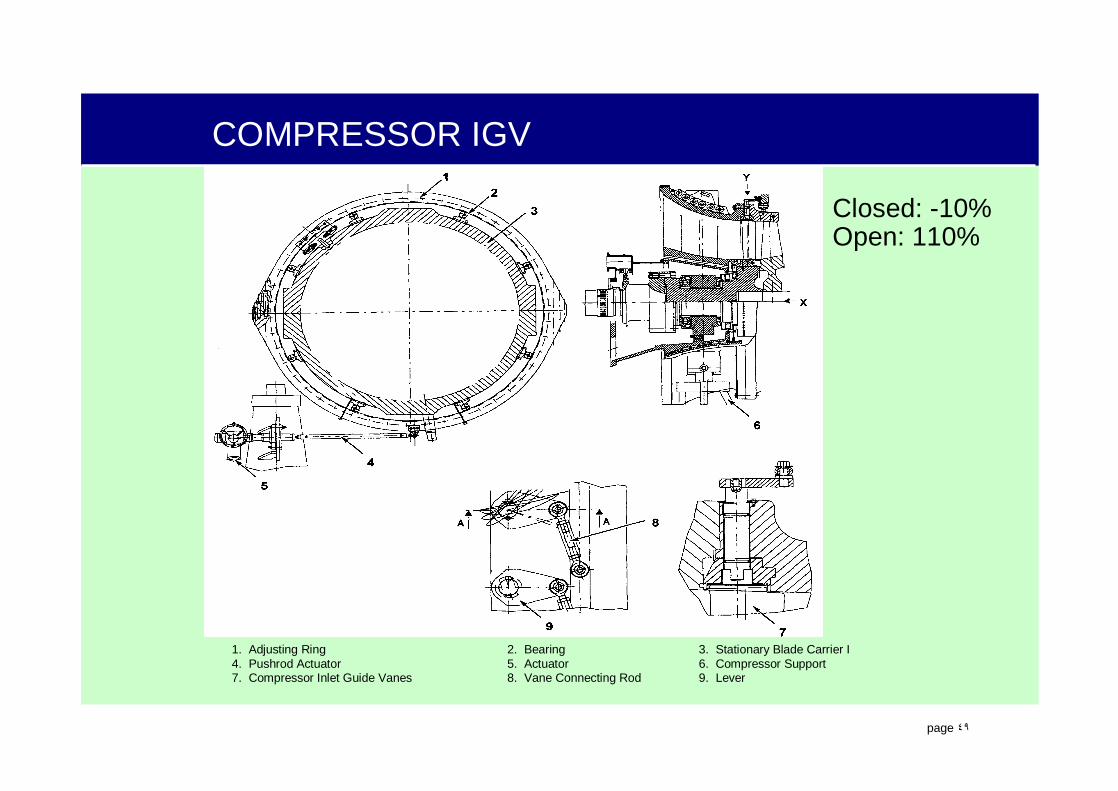
COMPRESSOR IGV
The inlet guide vanes (IGV’s) control the amount of air flowing through the compressor and turbine. Opening the inlet guide vanes (IGV’s) increases the amount of airflow. Closing the IGV’s decreases the amount of air flowing through the compressor and the turbine. The control system can maintain a constant fuel/air ratio by changing the fuel flow and airflow rates simultaneously. Maintaining a constant fuel/air ratio ensures that the corrected turbine outlet temperature (TATK) remains constant during load changes.

.
page ٤٨
COMPRESSOR IGV
The V94.3A IGV position can be varied between –10% (Fully closed) and110% (Fully Open)
During start–up, boiler purge and shutdown, the IGVs are positioned tofully closed.
When the rotor speed gets close to rated speed (~45 s-1, 2700 rpm), theIGV’s move to the ‘CLOSED’ position (~0%) to prevent compressor bladevibration problems.
When Corrected Turbine Outlet Temperature Reaches Its Setpoint,The IGV’s will commence opening towards their “Fully Open” position.
Increases the airflow through the compressor and turbine allowing the control system to continue to increase the amount of fuel while maintaining a constant corrected turbine outlet temperature.
When the IGV’s have reached their “Fully Open” position, any furtherincrease in load (fuel) will increase the corrected turbine outlettemperature.
.
page ٤٩
COMPRESSOR IGV
1. Adjusting Ring 2. Bearing 3. Stationary Blade Carrier I4. Pushrod Actuator 5. Actuator 6. Compressor Support7. Compressor Inlet Guide Vanes 8. Vane Connecting Rod 9. Lever
Closed: -10%Open: 110%

.
page ٥٠
COMPRESSOR INLET TEMPERATURE
Required to calculate the corrected turbine outlet temperature (TATK). Four dual–element RTD’s. One element from each RTD is used to calculate the average compressor inlet temperature. The other element is a spare.
MBA11CT101MBA11CT102MBA11CT103MBA11CT104

.
page ٥١
COMPRESSOR INLET PRESSURE/SURGE DETECTION
Compressor Inlet Pressure (MBA11CP101) measures the vacuum in the vertical intake duct.
Three Differential pressure switch (MBA11CP001, 002, 003) measures the pressure difference between the vertical intake duct and the compressor inlet, immediately upstream of the IGVs.
At turbine speeds greater than 42 s-1 (2520 rpm), if the differential pressure decreases below a specific level (approximately 30 mbar, 0.435 psi) a turbine trip is initiated to prevent compressor surge.
Compressor surges can be caused by:
• Operating the combustion turbine too slowly without opening the blowoff valves,
• Throttling the compressor IGV’s,
• Sudden uncontrolled combustion of fuel,
• Excessive combustion chamber pressure.

.
page ٥٢
COMPRESSOR OUTLET PRESSURE / TEMPERATURE
PRESSURE –
• Indication of cooling air supply.
• Indication of relative combustion chamber pressure loss.
• Signal used for limit control of the compressor outlet pressure gradient.
Two pressure transmitters, MBA12CP101 and MBA12CP102, are located downstream from the compressor outlet.
TEMPERATURE –
• Indication and control of the compressor outlet temperature.
• Indication of the burner temperature during premix.
The compressor outlet temperature dual-element thermocouples, MBA12CT101, 102 and 103, are located downstream from the compressor outlet
.
page ٥٣
TURBINE OUTLET TEMPERATURE
Twenty-four triple–element thermocouples, MBA26CT101 through 124
Equally spaced around the exhaust diffuser circumference directly downstream from the turbine exhaust.
The Operator Terminal displays all 24 individual readings and the corrected turbine outlet temperature (TATK).
The temperature controller uses the average turbine outlet temperature to calculate the corrected turbine exhaust temperature (TATK).
The combustion turbine temperature controller uses the TATK to adjust the fuel flow to respond to changes of temperature and hence changes in combustion.

.
page ٥٤
TURBINE OUTLET TEMPERATURE

.
page ٥٥
TURBINE OUTLET TEMPERATURE
.
page ٥٦
TURBINE OUTLET TEMPERATUREThe TXP uses the –B22 and –B23 elements to protect against three abnormal temperature conditions:
• A high temperature over the entire combustion area, • A hot spot near one thermocouple, and • Cold streaks.
The TXP uses only six thermocouple to detect overall HIGH TEMPERATURE.• High Temperature “ALARM” - >620ºC • High Temperature “Trip” - >660ºC.
All 24 thermocouples are used to detect HOT SPOTS or burner failures.• Each thermocouple is compared to the average temperature.• Hot Spot warning “HS WARN” - Any temperature differs from the average by >30ºC. • Hot Spot Trip - Any temperature differs by more than 50ºC.
If one or more burners extinguish, COLD STREAKS can form in the exhaust gas flow.• The turbine temperature protection system issues a warning “WARN” if two
extinguished burners are detected. • It will generate an alarm “GT–S/D” and initiate a normal shutdown if three adjacent
burners extinguish. • If four adjacent or 2 groups of 3 adjacent burners extinguish, the turbine will trip.

.
page ٥٧
GT TEMP TURB OUTLET
GT TEMP TURB OUTLET

.
page ٥٨
GAS TURBINE INTAKE AIR DRYING• During standstill, dehumidifier MBA10AT001, protects moisture–sensitive
turbine components from prolonged exposure to high humidity, condensation, and corrosive environments.
• 2 hours after shutdown begins, the shutdown sequence will close the motor–operated air inlet duct shutoff damper MBL20AA001 and turn on the dehumidifier.
• The combustion turbine control system automatically switches the dehumidifier off before startup.
Dehumidifier
Control Panel
ReactivationBlower
ProcessBlower
ReactivationAir Filter
Heater
DesiccantWheelHeaterReactivation
Air FilterReactivationBlower
ProcessBlower
.
page ٥٩
COMBUSTION CHAMBER INSTRUMENTATION
Used to :• Detect the pressure drop across the
combustion chamber• Combustion process instability (humming)• Flameout.

.
page ٦٠
COMBUSTION CHAMBER INSTRUMENTATION
Combustion chamber measuring instruments are used to detect the pressure drop across the combustion chamber, combustion process instability (humming), flashback, and flameout. In order to insure proper combustion. the combustion chamber is monitored in several ways.
• Differential pressure transmitter MBM10CP101 monitor the pressure across the burners.
• Pressure transmitter MBA12CP101 measures the compressor discharge pressure.
• The control system uses these pressure measurements to determine if the combustion process is stable or if the combustion process is becoming unstable and a quick changeover from premix to diffusion mode is required.
• Two dynamic pressure transducers, MBM11CP102 and MBM21CP102 are used to detect humming.
• Two Accelerometers, MBM11CY401 and MBM11CY402 are used to detectCC acceleration
• Temperature and flame monitoring are used to detect individual burner failure.
• Thermocouples located at the axial twirlers of each burner are used to detect flashback.

.
page ٦١
FLAME MONITORS
• Checks for presence of flames. And trips the turbine if there is no flame.
• Two monitoring systems– flame scanner– associated analog module– each scanner monitors a group of 7 burners– detect the radiation emitted by the flames– two photocells- a silicon cell and a lead–sulfide cell
sense flame radiation– cover a wave length range of approximately 350 –
2700 nm

.
page ٦٢
FLAME MONITORS
• During a gas turbine start, the flame monitoring system is activated approximately 9 seconds after an open command has been issued to the gas emergency stop valve. After an additional 3 seconds, the flame monitoring signal is released. If at this time the “flame on “ signal of at least one of the two monitoring systems is present, the startup sequence is may proceed.
• Hence, a gas turbine trip is only initiated if both flame monitors report that the flame intensity has dropped below the “flame off” limit for more than 1 second.

.
page ٦٣
MONITORING FLAME
MBM13CR101MBM13CR102 MBM13CR101
MBM13CR102

.
page ٦٤
HUMMING/ACCELERATION
• Gas turbines with hybrid burners may experience combustion instabilities manifested as elevated alternating pressure amplitudes in combustion chamber pressure, called combustion chamber humming. The alternating pressure amplitudes, or humming, causes vibrations to occur in the combustion chamber. These pressure changes must be quickly detected and eliminated to prevent a further rapid increase in alternating pressure amplitudes and the possible consequential damage to components of the combustion turbine.

.
page ٦٥
HUMMING/ACCELERATION
• Humming is detected by measuring the alternating pressure amplitudes of the combustion chamber pressure using the two dynamic pressure transducers MBM11CP101 and MBM11CP102 mounted on the turbine center casing. The two pressure transducers measure combustion chamber pressure fluctuations. A signal conditioning unit filters out other frequencies to give an output measure for each transducer as an effective value. Each effective value is sent to the TXP for monitoring purposes.
• Acceleration is detected by measuring the vibration of the combustion chamber using two (2) accelerometers, MBM10CY101 and MBM10CY102 mounted on the combustion chamber. The two accelerometers measure the vibration of the combustion chamber.
Limit Humming Setpoint Acceleration Setpoint
Limit 1 (GW1) 25 mbar 2.5 g
Limit 2 (GW2) 40 mbar 3 g
Limit 3 (GW3) 80 mbar 8 g

.
page ٦٦
HUMMING/ACCELERATION
Three limits are imposed associated with humming and acceleration,typical values are as follows:
> Limit 1 for 4 seconds the turbine output is rapidly reduced by 6 MW. If the limit is still exceeded the power is again reduced by 6 MW.
> Limit 2 for 1 second the gas turbine output is rapidly reduced by 15 MW. If the limit is still exceeded the power output is again reduced by 15 MW. In both cases if these power reductions do not mitigate the humming or acceleration the natural gas system is tripped resulting in a gas turbine trip.
If Limit 3 is exceeded the gas turbine is immediately tripped.
.
page ٦٧
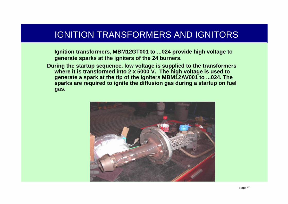
IGNITION TRANSFORMERS AND IGNITORS
Ignition transformers, MBM12GT001 to ...024 provide high voltage to generate sparks at the igniters of the 24 burners.
During the startup sequence, low voltage is supplied to the transformers where it is transformed into 2 x 5000 V. The high voltage is used to generate a spark at the tip of the igniters MBM12AV001 to ...024. The sparks are required to ignite the diffusion gas during a startup on fuel gas.

.
page ٦٨
GT BURNER TEMP MON
GT BURNER TEMP MON

.
page ٦٩
TXP INTRODUCTION
.
page ٧٠
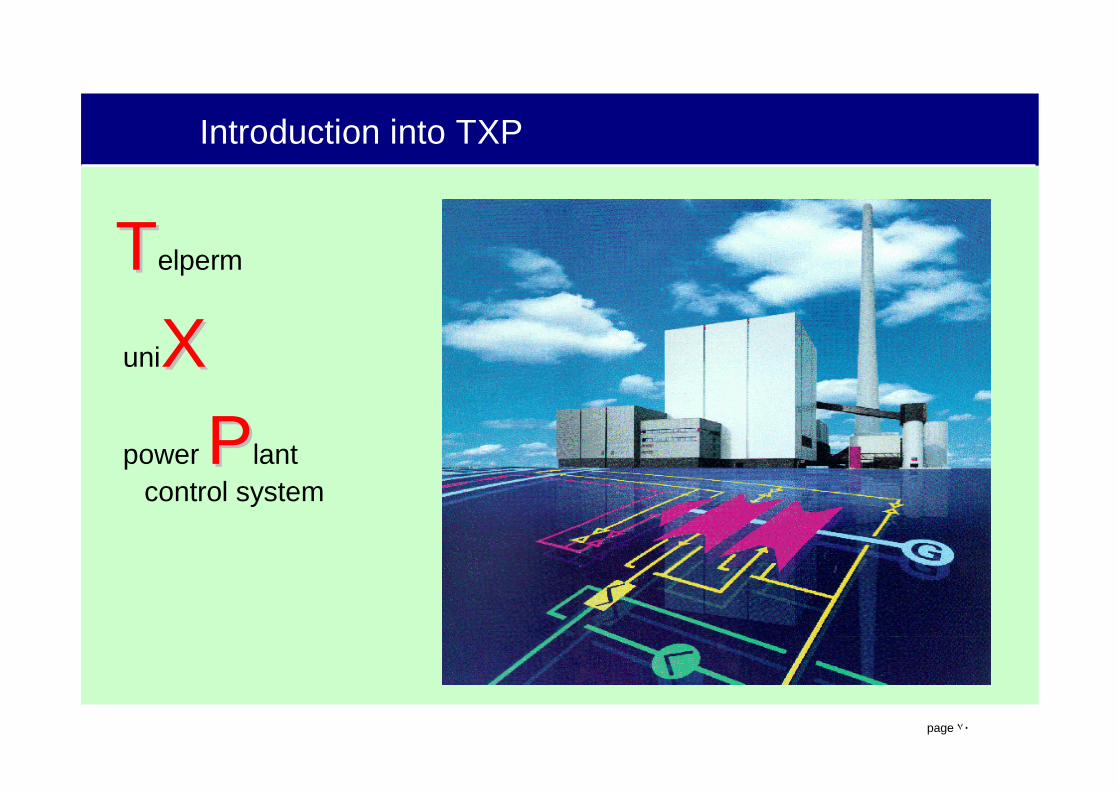
Introduction into TXP
TTelperm
uniXXpower PPlant
control system
.
page ٧١
Introduction into TXP
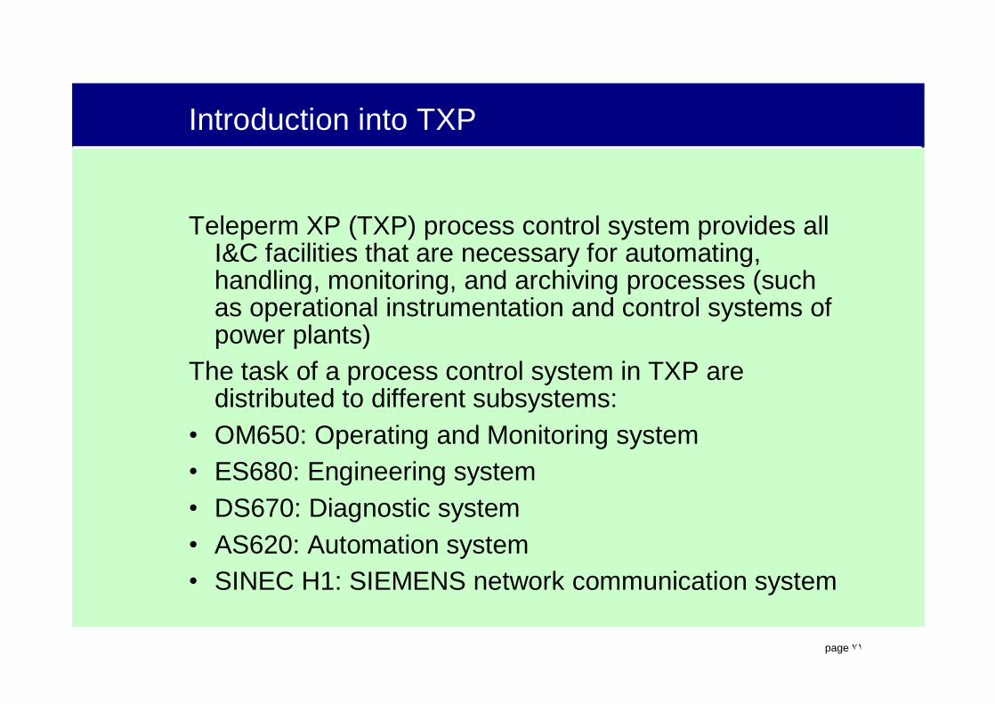
Teleperm XP (TXP) process control system provides all I&C facilities that are necessary for automating, handling, monitoring, and archiving processes (such as operational instrumentation and control systems of power plants)
The task of a process control system in TXP are distributed to different subsystems:
• OM650: Operating and Monitoring system• ES680: Engineering system• DS670: Diagnostic system• AS620: Automation system• SINEC H1: SIEMENS network communication system

.
page ٧٢
The structure of TXP
SIMATIC NET Industrial EthernetSIMATIC NET Industrial Ethernet
ES 680ES 680EngineeringEngineeringSystemSystem
OM 650OM 650Operation and Operation and Management Management
SystemSystem
DS 670DS 670DiagnosticsDiagnosticsSystemSystem
CT 675CT 675CommissioningCommissioningToolTool
AS 620AS 620AutomatioAutomationnSystemSystem
Modular - Several software modules work together,
Distributed - Tasks are ‘distributed’ across several pieces of hardware,
Function Oriented -Similar functions are grouped together.Module : component, unit, subsystem
Modular : made of standardized units which can be assembled in different ways
.
page ٧٣
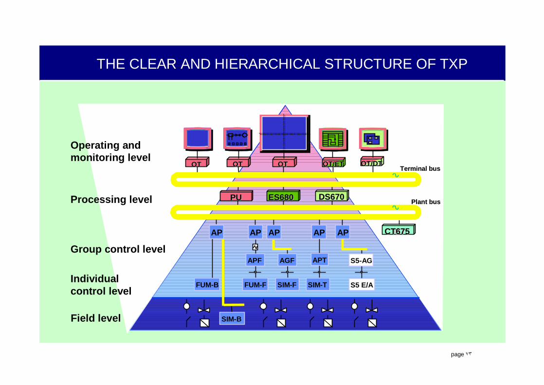
THE CLEAR AND HIERARCHICAL STRUCTURE OF TXP
Operating andmonitoring level
Field level
Processing level
OTOT OTOT OTOT
AGF
APAP
S5-AG
S5 E/ASIM-TSIM-FFUM-F
AP
FUM-B
Group control level
PUPU ES680ES680 DS670DS670
AP
APTAPF
SIM-B
OT/ETOT/ET
CTCT675CT675AP
OT/DTOT/DT
Individualcontrol level
Plant busPlant bus
Terminal busTerminal bus

.
page ٧٤
TXP FUNCTIONS
Several Major Functions are required to accomplish the complex task of Power Plant Control.

.
page ٧٥
TXP FUNCTIONS
The OM650 process control and information system is the interface between the system and operator in the control room. This highly ergonomic window to the process enables the process to be centrally monitored and controlled. In addition the system provides all functions that are required for logging the process and for archiving the data.
The ES680 engineering system is the central configuration system of TXP. ES680 is used for configuring the AS620 automation system, the OM650 process control and information system, the SINEC H1 FO bus system, and the necessary hardware. ES680 centrally administers all configuration data.
The configuration of the AS functions and processing functions in OM is based on control system flow charts to VGB guidelines

.
page ٧٦
TXP FUNCTIONS
The DS670 diagnostic system is the tool that is used for monitoring and detecting malfunctions in the I&C components of TXP.
In the event of malfunction, the diagnostic system swiftly takes the user to the source of the fault and informs about cause and possible elimination of the fault
The network structure of the SINEC H1 bus system enables communication between the individual subsystems of the process control system. The bus system complies with the international standards and consequently offers the prerequisites of open communication.

.
page ٧٧
TXP FUNCTIONS in hierarchy structure
.
page ٧٨
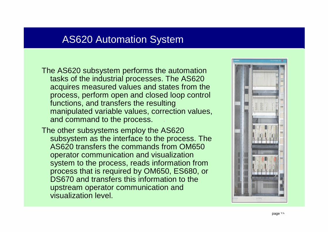
AS620 Automation System
The AS620 subsystem performs the automation tasks of the industrial processes. The AS620 acquires measured values and states from the process, perform open and closed loop control functions, and transfers the resulting manipulated variable values, correction values, and command to the process.
The other subsystems employ the AS620 subsystem as the interface to the process. The AS620 transfers the commands from OM650 operator communication and visualization system to the process, reads information from process that is required by OM650, ES680, or DS670 and transfers this information to the upstream operator communication and visualization level.

.
page ٧٩

.
page ٨٠
AS620 B Automation System
The AS620 Automation System is divided to following subsystems:
AS620 B: basic system for general automation tasks, system and unit protection, closed loop control. Central structure or distributed arrangement using buses are both possible.
• FUM-B variant: in a central structure, FUM modules (function modules) are used for connecting the sensors and actuators of the process.

.
page ٨١
AS620 B Automation System
• SIM-B variant: SIM modules (signal modules) enable a distributed structure to be set up (locally, in vicinity to the process). A bus connected the SIM modules with the central system components.
.
page ٨٢
AS620 Automation System
AS620 F: fail-safe for protection and control tasks that require TUV approval (e.g. burner control).
Single and fault-tolerant structures are both possible, including the variants with the fail-safe automation processor (APF) and the fail-safe programmable logic controller (AG-F).
• FUM-F variant: configuration with the fail-safe APF automation processor and the related FUM-F modules (fail-safe function modules)
• SIM-F variant: configuration with the AG-F programmable logic controller. This variant employs the SIMATIC S5 AG S5-115F programmable logic controller with SIM-F modules.
AS620 T: Turbine controller and other high-speed control tasks at the turbine unit.
Auxiliaries connection: signal exchange with the SIMATIC S5 units. The SIMATIC units contain the implementation of a complete automation task that is not configured via ES680.
.
page ٨٣
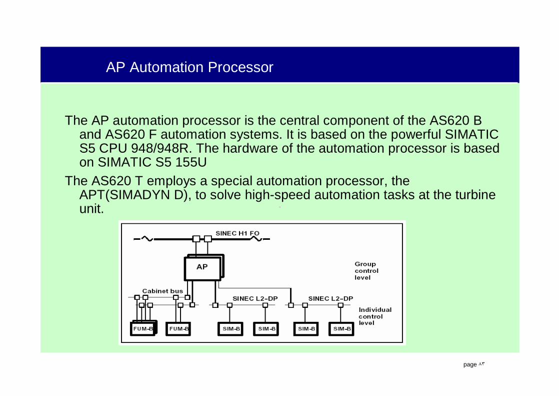
AP Automation Processor
The AP automation processor is the central component of the AS620 B and AS620 F automation systems. It is based on the powerful SIMATIC S5 CPU 948/948R. The hardware of the automation processor is based on SIMATIC S5 155U
The AS620 T employs a special automation processor, the APT(SIMADYN D), to solve high-speed automation tasks at the turbine unit.
.
page ٨٤
AS620T - FAST, CLOSED-LOOP CONTROL FOR TURBINES
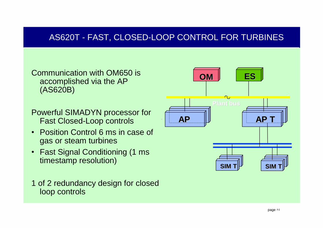
Communication with OM650 is accomplished via the AP (AS620B)
Powerful SIMADYN processor for Fast Closed-Loop controls
• Position Control 6 ms in case of gas or steam turbines
• Fast Signal Conditioning (1 ms timestamp resolution)
1 of 2 redundancy design for closed loop controls
Plant busPlant bus
SIM TSIM T
APAP
SIM TSIM T
AP TAP T
OMOM ESES

.
page ٨٥
GAS TURBINE CONTROLLER
DESCRIPTIONThe functions of the gas turbine controller are performed in different parts of the automation system. The controller itself is the AS 620 T (SIMADYN D). The gas turbine controller also uses the AS 620 F for the turbine protection functions and the AS 620 B for the open-loop control of the turbine.
The gas turbine controller is connected directly to the plant bus. Communication between the controller and the operation and monitoring system or the other components of the automation system is accomplished by a function block in one of the automation processors of basic automation system (AS620B).
Operation and monitoring of the gas turbine controller is done from the Operation and Monitoring System (OM Screens).

.
page ٨٦
AS 620 F
Plant bus
Operation and Monitoring SystemOM 650
AS 620 TTurbine
Open - LoopControl
TurbineProtection
Gas Turbine Controller
InternalBus
Simadyn D
Plant
LiveSignal
AS 620 B
Function blockfor gas turbine
controllerCPUAPT "B"
CPUAPT "A”
GAS TURBINE CONTROLLER HARDWARE CONFIGURATION
.
page ٨٧
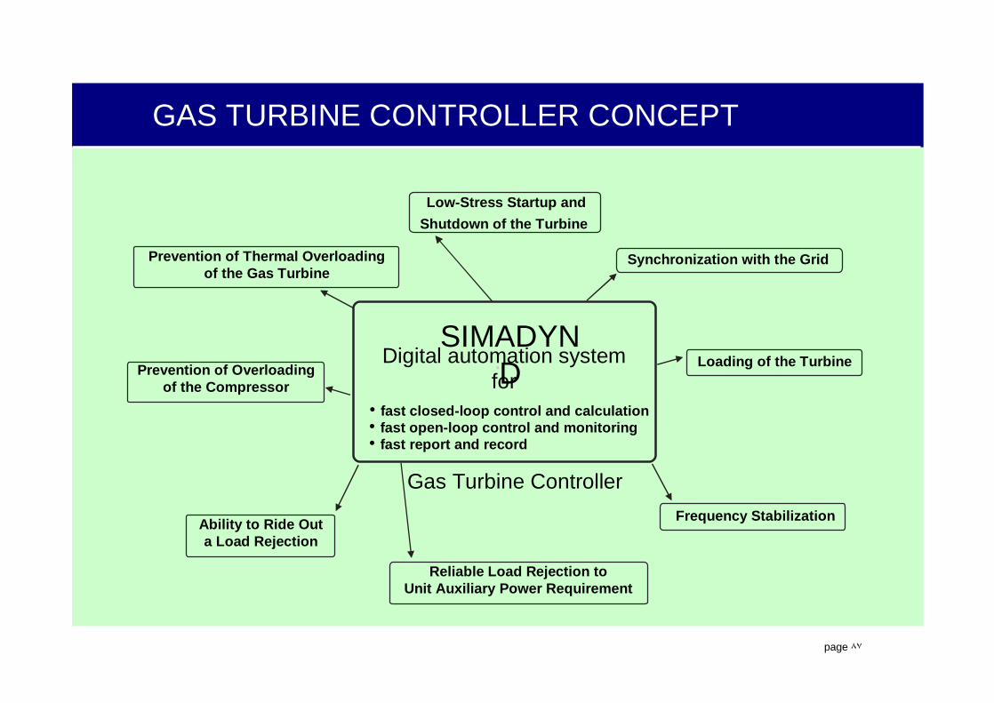
Synchronization with the Grid
Loading of the Turbine
Gas Turbine Controller
SIMADYN D
Digital automation systemfor
• fast closed-loop control and calculation• fast open-loop control and monitoring• fast report and record
Frequency Stabilization
Reliable Load Rejection toUnit Auxiliary Power Requirement
Ability to Ride Outa Load Rejection
Prevention of Thermal Overloadingof the Gas Turbine
Prevention of Overloadingof the Compressor
Low-Stress Startup andShutdown of the Turbine
GAS TURBINE CONTROLLER CONCEPT

.
page ٨٨
TYPICAL OM650 STRUCTURE WITH EXTERNAL GATEWAY
Comprised of:• Operator Terminals (OT)
– Man - Machine Interface– Up to 40 may be
connected to the Terminal Bus.
– Up to 4 screens attached to a single OT.
– Color and Alarm printers– Mouse driven (standard
keyboard optional)• Processor Unit(s)
– Information channel for man-machine interfaces.
– Plant Process ‘traffic cop’• Server Unit
– Support functions– Not required for process
control
ExternalExternal
PU/SUPU/SUPUPU ...
...
Terminal busTerminal bus
...
NetworkNetwork
Bridge/Bridge/GatewayGateway
Plant busPlant bus
1 . . . 41 . . . 4
OTOTOTOTOTOT
Barco/EOSBarco/EOS Barco/EOSBarco/EOS
1 . . . 41 . . . 4
Barco/EOSBarco/EOS
.
page ٨٩
.
page ٩٠
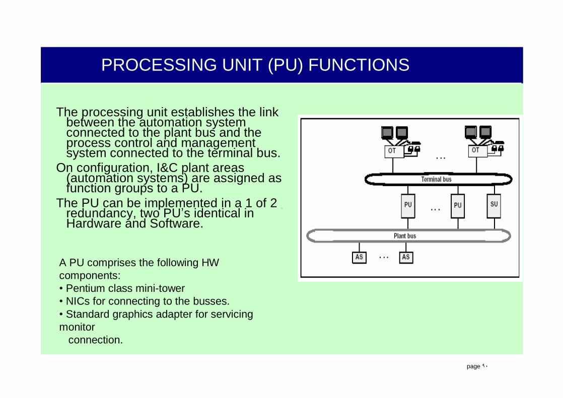
PROCESSING UNIT (PU) FUNCTIONS
The processing unit establishes the link between the automation system connected to the plant bus and the process control and management system connected to the terminal bus.
On configuration, I&C plant areas (automation systems) are assigned as function groups to a PU.
The PU can be implemented in a 1 of 2 redundancy, two PU’s identical in Hardware and Software.
A PU comprises the following HW components:• Pentium class mini-tower• NICs for connecting to the busses.• Standard graphics adapter for servicing monitor
connection.
.
page ٩١
PROCESSING UNIT (PU) FUNCTIONS
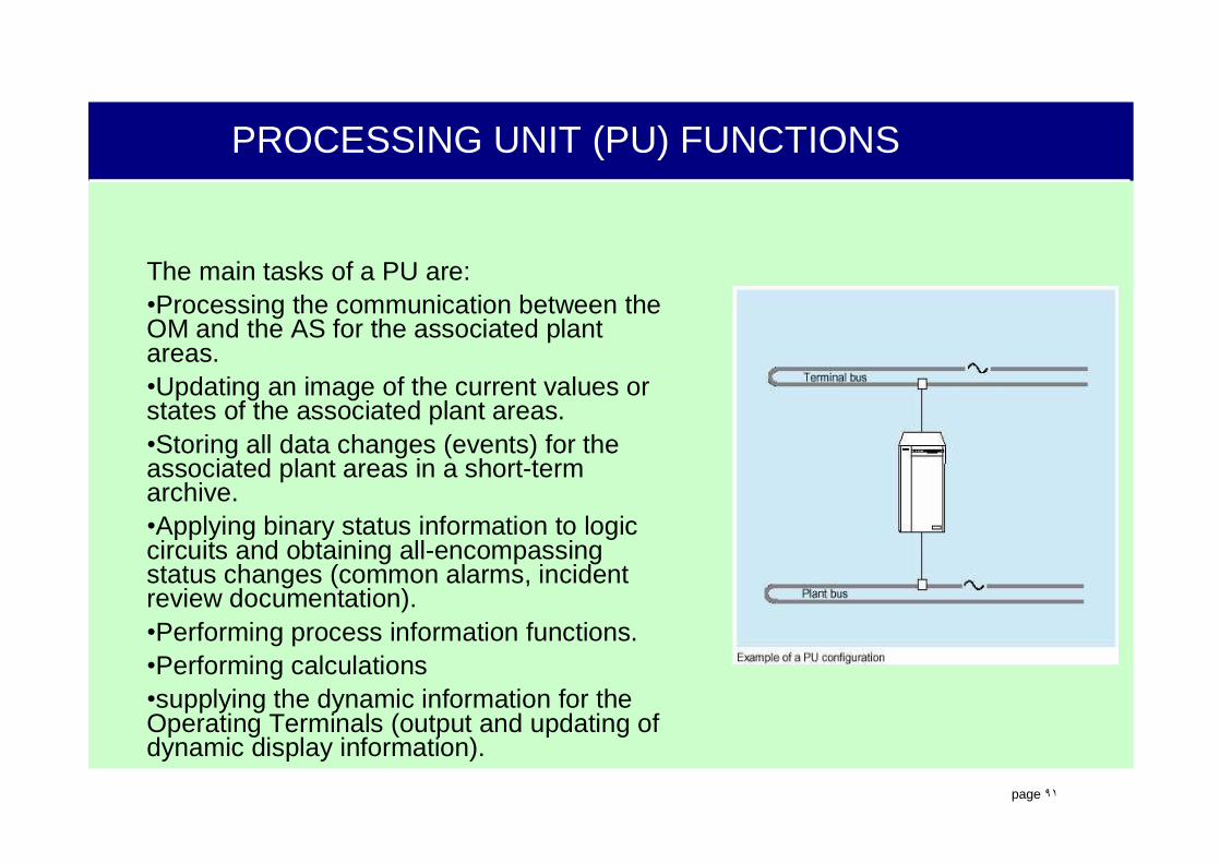
The main tasks of a PU are:•Processing the communication between the OM and the AS for the associated plant areas.•Updating an image of the current values or states of the associated plant areas.•Storing all data changes (events) for the associated plant areas in a short-term archive.•Applying binary status information to logic circuits and obtaining all-encompassing status changes (common alarms, incident review documentation).•Performing process information functions.•Performing calculations•supplying the dynamic information for the Operating Terminals (output and updating of dynamic display information).

.
page ٩٢
SERVER UNIT (SU) FUNCTIONS
The Server Unit (SU) is responsible for the central functions of long-term archiving and logging as well as for supply descriptive data.The SU is only connected to the terminal bus via which the communication between the PU’s and OT’s is processed. At least one MOD is connected for exporting long term archive data.The SU is always implemented regardless of the number of PU’s used.
An SU comprises the following HW components:• Pentium class mini-tower• NIC for connecting to the Terminal Bus.• Standard graphics adapter for servicing monitor
connection.
The main tasks of the SU are:• Managing data descriptions planned on the ES 680 in a
central database. This information is used mainly by the MMI and log functions through out the terminal bus (administrative) network.
• Log functions.• Long-term Archiving with external data storage.
The SU can be implemented in a 1 of 2 redundancy, two SU’s identical in Hardware and Software.

.
page ٩٣
OTOTTerminal bus Terminal bus
PUPU
Plant bus Plant bus
ASAS
Short term archive Short term archive
Ring memoryRing memoryadjustableadjustable
500 000 signals 500 000 signals
Short term archive ofall data in the PU(signals, statuses,calculated values and alarms)Binary and analog
Storage capacity forall signals appr. 8 hours
Transfer of the data into the long term archive every 20 sec.
Design of the short termarchive organized in theRAM as a ring memory
DATA STORAGE WITH OM 650SHORT TERM ARCHIVE

.
page ٩٤
SUSU
OTOTTerminal bus Terminal bus
PUPU
Plant bus Plant bus
ASAS
Long term archive Long term archive Long term archive for alldata with same density as in the short term archive
harddisc
Storage capacity for allSignals approx. 8 days
Design of the long termarchive organized on theharddisc as a ring memory
Transfer of data to MOD
Direct access to all dataOn MOD
MODMODRing memoryRing memory
12 x 1012 x 1066 signalssignalsextendable extendable
Storage capacity on MODApprox. 16 days
DATA STORAGE WITH OM 650LONG TERM ARCHIVE
.
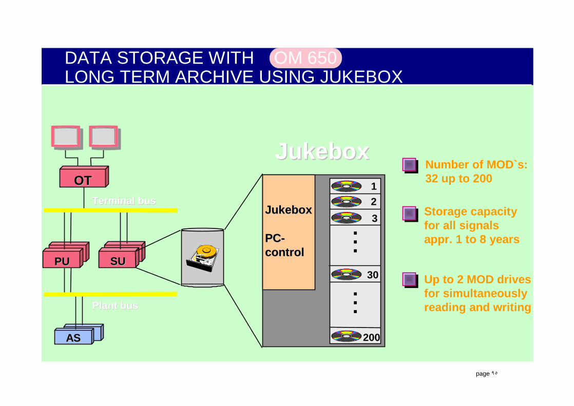
page ٩٥
DATA STORAGE WITH OM 650LONG TERM ARCHIVE USING JUKEBOX
SUSU
OTOTTerminal bus Terminal bus
PUPU
Plant bus Plant bus
ASAS
Number of MOD`s:32 up to 200
Storage capacityfor all signalsappr. 1 to 8 years
Up to 2 MOD drivesfor simultaneouslyreading and writing
JukeboxJukebox
PC-PC-controlcontrol
123
200
...
JukeboxJukebox
30...
.
page ٩٦
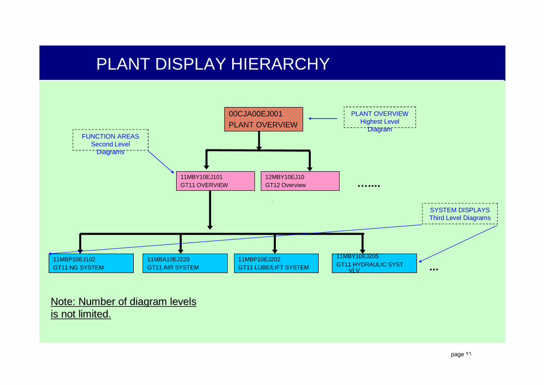
PLANT DISPLAY HIERARCHY
00CJA00EJ001PLANT OVERVIEW
11MBY10EJ101GT11 OVERVIEW
12MBY10EJ10GT12 Overview …....
11MBP10EJ102GT11 NG SYSTEM
11MBA10EJ220GT11 AIR SYSTEM
11MBP10EJ202GT11 LUBE/LIFT SYSTEM
11MBY10EJ205GT11 HYDRAULIC SYST
VLV
Note: Number of diagram levelsNote: Number of diagram levelsis not limited. is not limited.
PLANT OVERVIEWHighest Level
DiagramFUNCTION AREAS
Second Level Diagrams
SYSTEM DISPLAYSThird Level Diagrams
...
.
page ٩٧
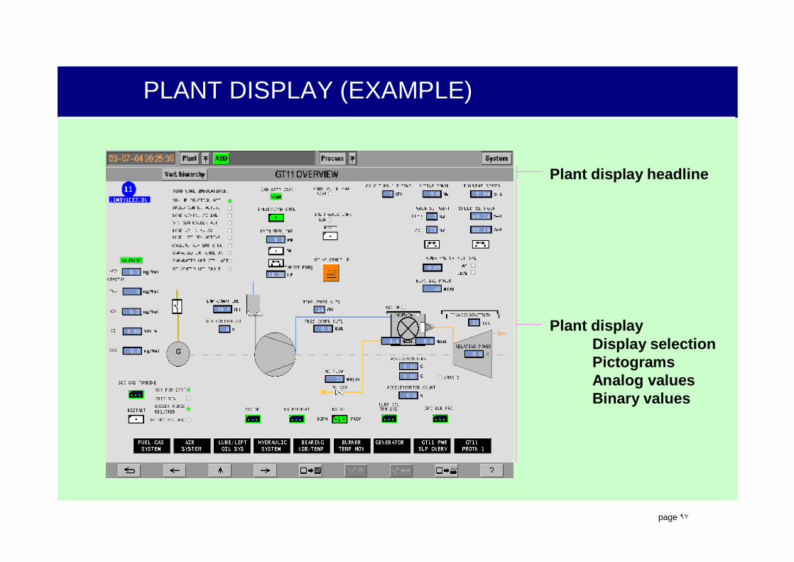
PLANT DISPLAY (EXAMPLE)
Plant display headline
Plant displayDisplay selectionPictogramsAnalog valuesBinary values

.
page ٩٨
DISPLAY SCREEN STRUCTURE
Screen Header
Display Area
Screen Footer

.
page ٩٩
SCREEN HEADER
Current System Date and Time
Plant Pull-Down Menu Button
Plant Overview Display Button
Common Alarm Indicators (CAI)
Process Display Overview (Trends) Button
System Pull-Down Menu Button
Horizontal Hierarchy Display Menu Selection Button
Vertical Hierarchy Display Menu Selection Button
Alarm Sequence Display (ASD)
Display Title
.
page ١٠٠
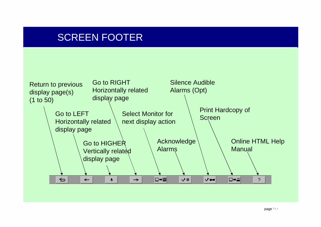
SCREEN FOOTER
Return to previous display page(s)(1 to 50)
Go to LEFT Horizontally related display page
Go to HIGHER Vertically related display page
Go to RIGHT Horizontally related display page
Select Monitor for next display action
Acknowledge Alarms
Silence Audible Alarms (Opt)
Print Hardcopy of Screen
Online HTML Help Manual
.
page ١٠١
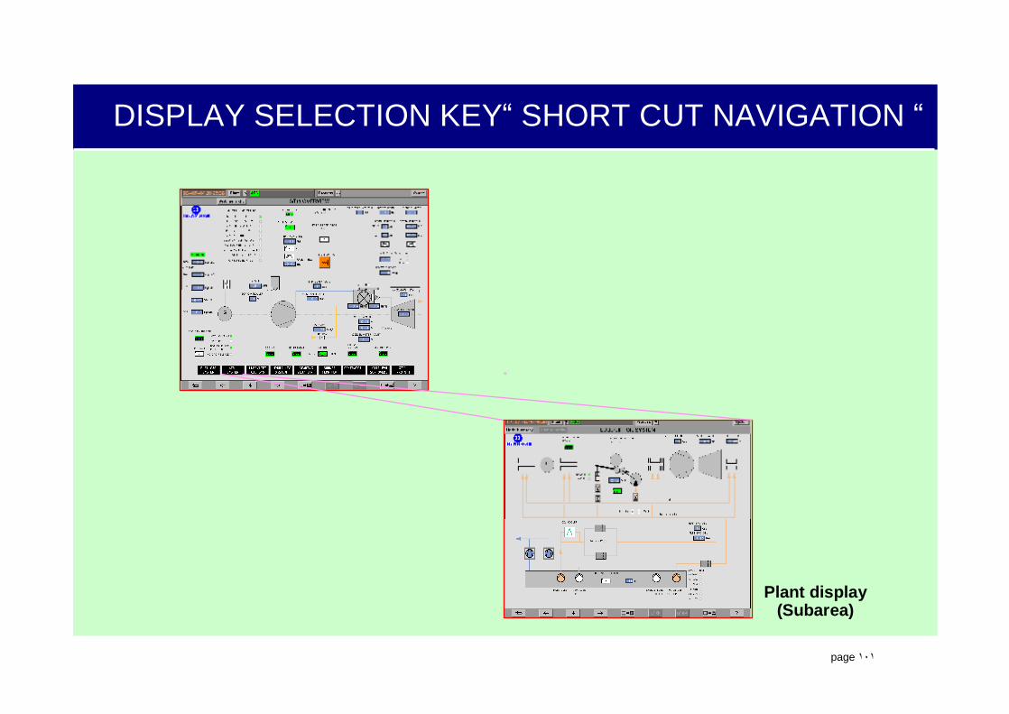
DISPLAY SELECTION KEY“ SHORT CUT NAVIGATION “
Plant display(Subarea)

.
page ١٠٢
Analog and Digital Signals flow from left to right, top to bottom.
The FUP can be made dynamic, showing live analog and digital signals, useful during troubleshooting and tuning
PROCESS SOLUTIONS ARE DESIGNED WITH THE ES680 AND THE YFR LOGIC DIAGRAMS (FUP)
OutputsOutputs
Signal flowSignal flow
InputsInputs

.
page ١٠٣
LOGIC DIAGRAM (NAVIGATION)
Signal finding through directlogic diagram navigation
>1
&
>1
&
OFF ON
Follow up diagram available
Follow updiagram not available
.
page ١٠٤
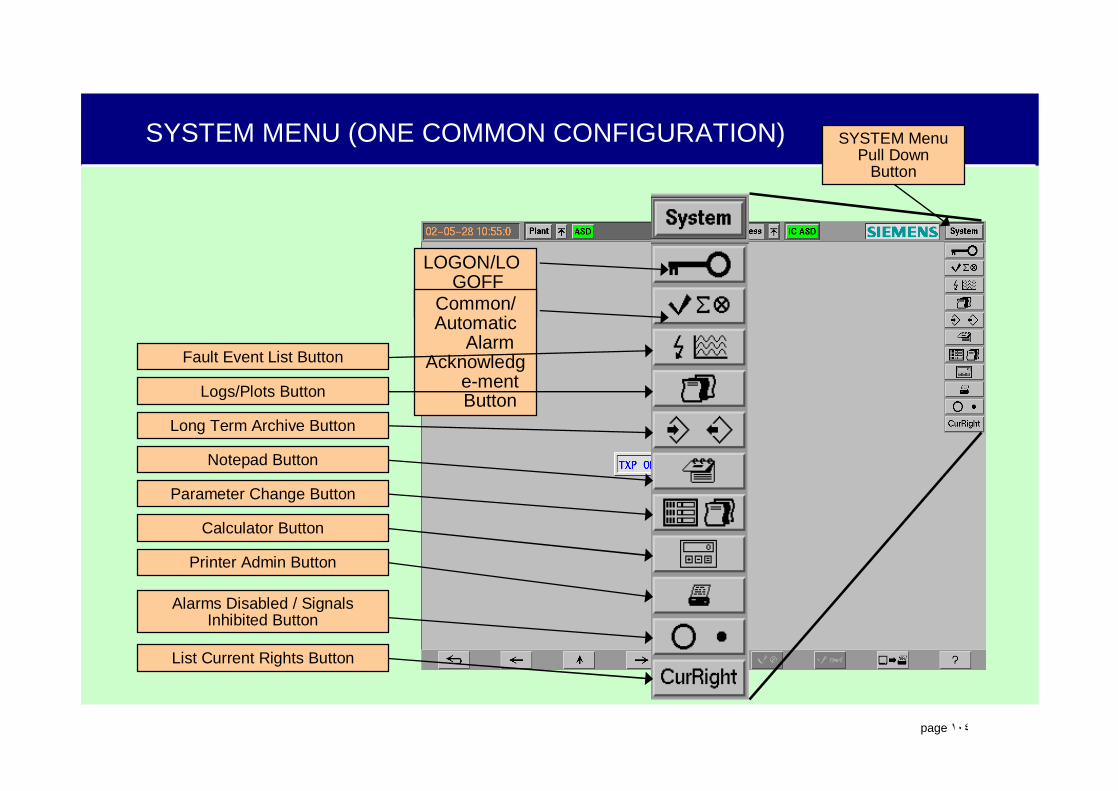
SYSTEM MENU (ONE COMMON CONFIGURATION)
LOGON/LOGOFF ButtonCommon/
Automatic Alarm
Acknowledge-mentButton
Fault Event List Button
Logs/Plots Button
Long Term Archive Button
Notepad Button
Parameter Change Button
Calculator Button
Printer Admin Button
Alarms Disabled / SignalsInhibited Button
List Current Rights Button
SYSTEM MenuPull Down
Button

.
page ١٠٥
DYNAMIC PICTOGRAPHS
MValves &Dampers
TEXTFault/Status Indicators
Flame 0Numerical
1Pre-SelectionDeviceSwitch Over
Sub Loop Controller
23Sub Group Controller
Set PointController
Continuous Controller
Motor Pump Fan Heater Breaker
INDICATORS
COMPONENTS
CONTROLLERS
Trend Selection Key
Display Selection Key
KEYS

.
page ١٠٦
POP-UP WINDOW STRUCTURE
Window Extension #1 (Mini-ASD)
Window Extension #2
Relocation Bar
Acknowledge Alarms
Acknowledge Manual Tracking Alarms
Engage / Disengage
Logic Diagram
Detail Window
Notebook
Close Pop-Up Window
Execute Selected Command
Freely Configurable (from ES680)
Error Messages
Enable / Disable
Manual Tracking Alarms(Type O -12 max)
System type Alarms (12 max)
Point Identification
Operation and Display Area
.
page ١٠٧
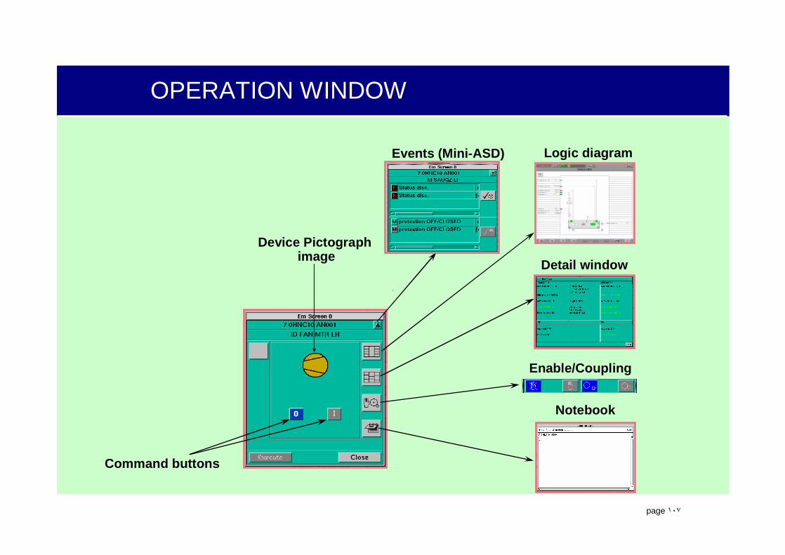
OPERATION WINDOW
Events (Mini-ASD) Logic diagram
Detail window
Notebook
Enable/Coupling
Device Pictographimage
Command buttons
.
page ١٠٨
BLOCK / ENABLE BUTTON
Manual Command
buttons
Block/EnableManual Commands (Buttons)
Block
Enable
AOFF
AON
CBOFF
CBOFF
OMSLC
Block/EnableAutomatic Inputs
Block
Enable
Automatic inputs

.
page ١٠٩
DRIVE CONTROL OPERATING WINDOW
Device Feedback:Off/Closed : white
On/Open : System Color
Other Components using thisOperating-Window
Heater
Fan
PumpBreaker
Damper
Off On Close Open
.
page ١١٠
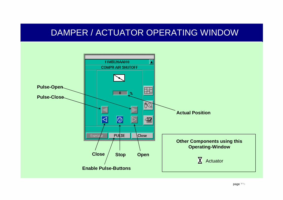
DAMPER / ACTUATOR OPERATING WINDOW
Enable Pulse-Buttons
Close OpenStop
Pulse-Close
Pulse-Open
Actual Position
Other Components using thisOperating-Window
Actuator

.
page ١١١
CONTROLLER OPERATING WINDOW “CONTROL VALVE”
Enable / Disable+
Coupling / Decoupling
Notebook
Actual Position
Controller Deviation
Pulse-Open
Pulse-Close
Automatic / ManualButton
Close Stop Open

.
page ١١٢
CONTINUOUS CONTROLLER
Also known as a Manual/Auto Station.
Function: (continuously) position a component to a desired position based on Manual input or Automatic comparison of a plant process actual value (AV) to a setpoint (SP)
Modes:Manual - Operator determines the
required VALVE position (Y).Auto (closed loop control) - TXP
positions valve to desired value (Y) based on SP-AV deviation (error signal).
.
page ١١٣
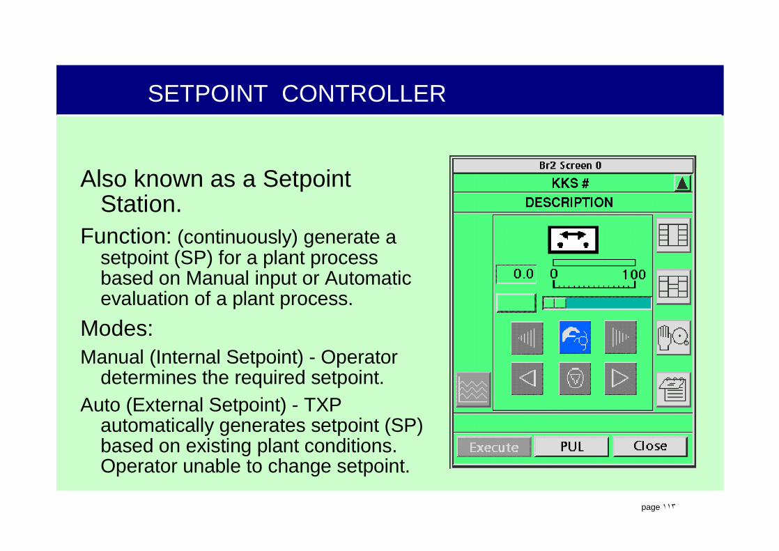
SETPOINT CONTROLLER
Also known as a Setpoint Station.
Function: (continuously) generate a setpoint (SP) for a plant process based on Manual input or Automatic evaluation of a plant process.
Modes:Manual (Internal Setpoint) - Operator
determines the required setpoint.Auto (External Setpoint) - TXP
automatically generates setpoint (SP) based on existing plant conditions. Operator unable to change setpoint.
.
page ١١٤
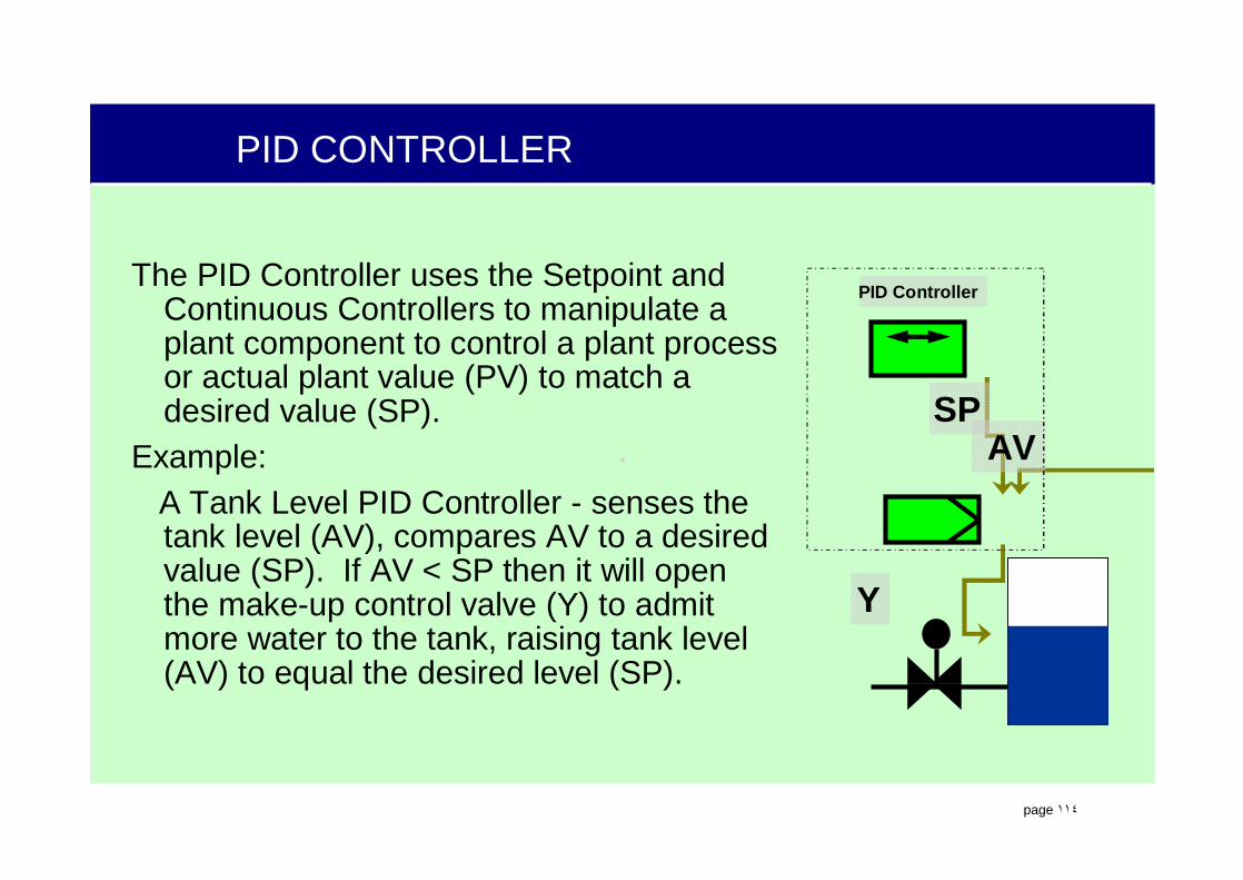
PID CONTROLLER
The PID Controller uses the Setpoint and Continuous Controllers to manipulate a plant component to control a plant process or actual plant value (PV) to match a desired value (SP).
Example:A Tank Level PID Controller - senses the tank level (AV), compares AV to a desired value (SP). If AV < SP then it will open the make-up control valve (Y) to admit more water to the tank, raising tank level (AV) to equal the desired level (SP).
Y
SPAV
PID Controller
.
page ١١٥
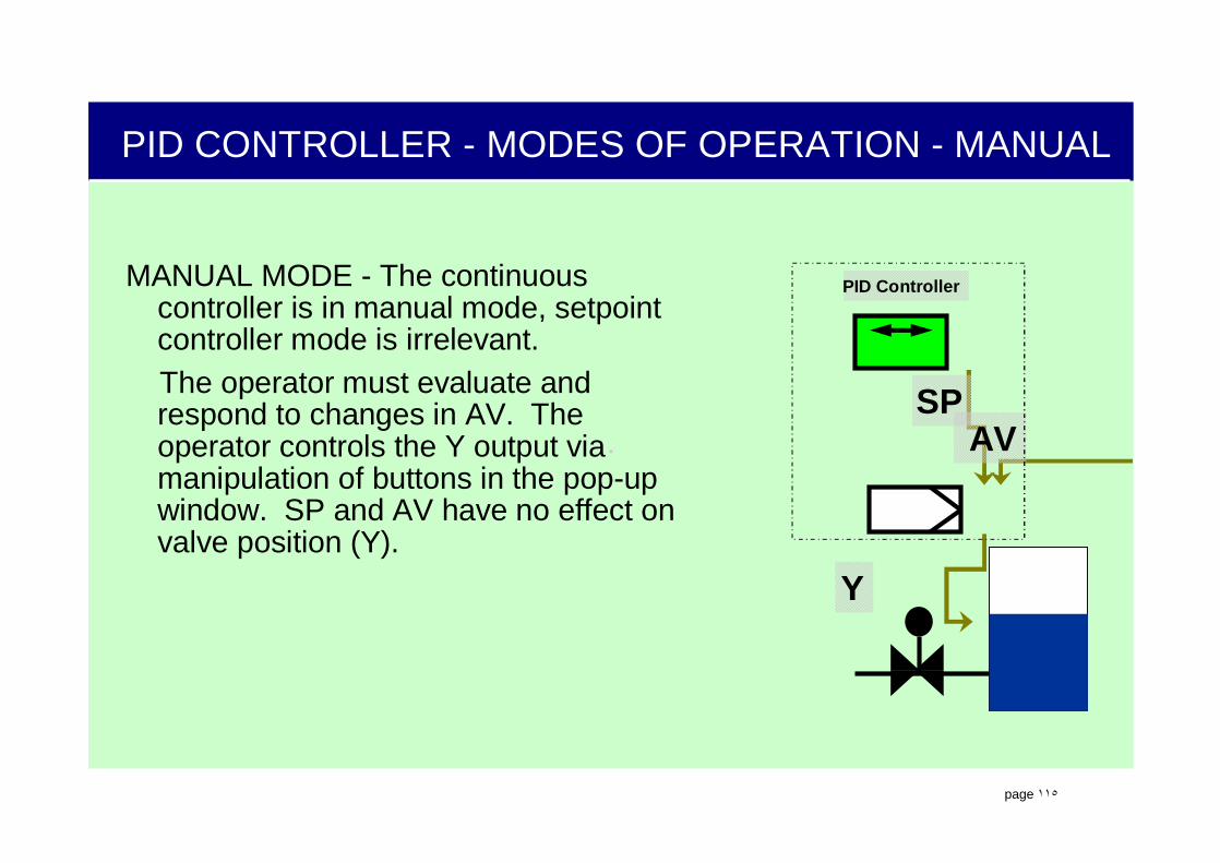
PID CONTROLLER - MODES OF OPERATION - MANUAL
MANUAL MODE - The continuous controller is in manual mode, setpoint controller mode is irrelevant.The operator must evaluate and respond to changes in AV. The operator controls the Y output via manipulation of buttons in the pop-up window. SP and AV have no effect on valve position (Y).
Y
SPAV
PID Controller
.
page ١١٦
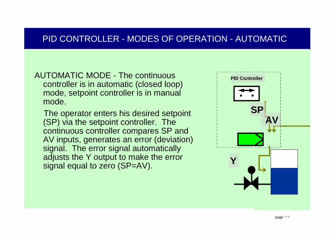
PID CONTROLLER - MODES OF OPERATION - AUTOMATIC
AUTOMATIC MODE - The continuous controller is in automatic (closed loop) mode, setpoint controller is in manual mode.The operator enters his desired setpoint (SP) via the setpoint controller. The continuous controller compares SP and AV inputs, generates an error (deviation) signal. The error signal automatically adjusts the Y output to make the error signal equal to zero (SP=AV). Y
SPAV
PID Controller

.
page ١١٧
PID CONTROLLER - MODES OF OPERATION - CASCADE
CASCADE MODE - The continuous controller is in automatic (closed loop) mode, setpoint controller is in automatic (closed loop) mode.The operator is unable to adjust SP or Y. The setpoint controller’s output (SP) is automatically determined and adjusted based on plant conditions. As in Automatic Mode, the continuous controller compares SP and AV inputs, generates an error (deviation) signal. This error signal automatically adjusts the Y output to make the error signal equal to zero (SP=AV).
Y
SPAV
PID Controller

.
page ١١٨
SETPOINT OPERATING WINDOW
Decrease IncreaseStop Enable Pulse-Buttons
Pulse-Decrease
Pulse-Increase
Operation Limits
Actual Setpoint
Slider
.
page ١١٩
PID-CONTROLLER FUNCTION PLAN
A_Open/Close = Automatic Open/CloseR_Open/Close = Release Open/CloseS_Open/Close = Protection Open/Close
A_CON = Auto-ControlR_CON = Release ControlA_MAN = Auto ManualR_MAN = Release ManualRM_Open/Close = Checkback Open/CloseRM_CON/MAN = Checkback Auto/Manual
.
page ١٢٠
SGC OPERATING WINDOW
Shutdown StartupSGCOn / Off
Waiting-Time
Monitoring-Time
Operator Guide ModeButton & Indicator
Step Branch
Go Next Step
Next Step
Actual Step(Step-Set)
Select StepJump to
selected Step
Other Components usingthis
Operating-WindowGC
.
page ١٢١
SGC FUNCTION PLAN
F_OPER/STIL = Flickering SU/SDA_OPER/STIL = AUTO SU/SDR_OPER/STIL = Release SU/SDSA_OPER/STIL = Protection SU/SDA_OFF/ON = Auto SGC OFF/ONSTEP OPER/STIL = SGC Steps SU/SDRM_OPER/STIL = Checkback SU/SDCB_RT = Checkback MonitoringCB_A_OFF/ON = Checkback SGC OFF/ON
.
page ١٢٢
DS670:Alarm Sequence Display (ASD)

.
page ١٢٣
ALARM EVENT TYPES (PRIORITIES)
An arriving alarm of the event type A indicates that an alarm limit was exceeded.
An arriving alarm of the event type W indicates that a warning limit was exceeded
An arriving alarm of the event type T indicates that a tolerance limit was exceeded.
An arriving alarm of the event type F indicates that an individual function in the I&C system is faulty.
An arriving alarm of the event type O indicates that there is a Manual Operator Adjustment event thatoccurred.
An arriving alarm of the event type S indicates that there is a fault in the I&C system which affectsseveral functions (Super ordinate I&C)
An arriving alarm of the event type L indicates that a local fault has occurred.
An arriving alarm of the event type C indicates that a status has changed
An arriving alarm of the event type M indicates that a Maintenance Action is required.

.
page ١٢٤
ALARM HIERARCHY
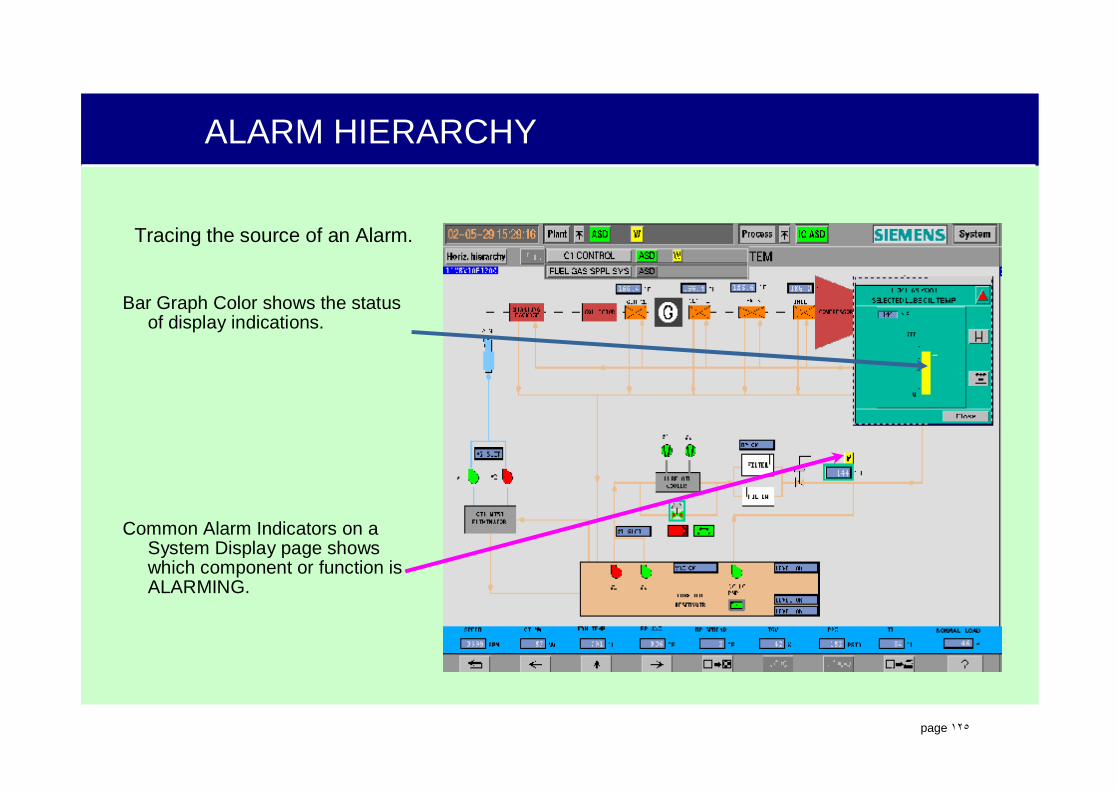
Tracing the source of an Alarm.
Common Alarm Indicators in the Header signify that there is that type of Alarm somewhere in the plant.
Common Alarm Indicators in the Plant Menu signify in which Function Area that the type of Alarm is located.
.
page ١٢٥
ALARM HIERARCHY
Tracing the source of an Alarm.
Common Alarm Indicators on a System Display page shows which component or function is ALARMING.
Bar Graph Color shows the status of display indications.
.
page ١٢٦
ALARM SEQUENCE DISPLAY - FA OVERVIEW
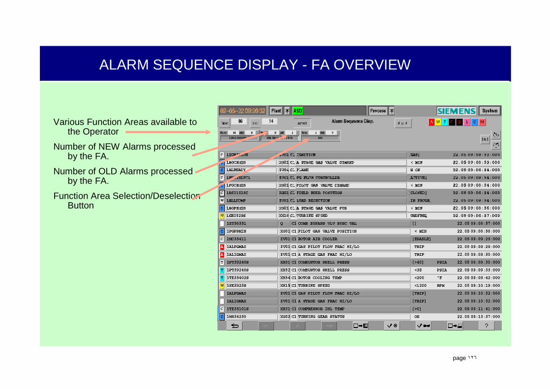
Various Function Areas available to the Operator
Number of NEW Alarms processed by the FA.
Number of OLD Alarms processed by the FA.
Function Area Selection/DeselectionButton

.
page ١٢٧
ALARM SEQUENCE DISPLAY
Function Area Overview - Statuses of the entire plant ASD and the individual FA ASDs.
Alarm Display - Chronological listing of Alarm Events that have been recorded by the ASD.
• Up to 21 Alarm Events may be listed
• May be configured for Newest on Top or Newest on Bottom

.
page ١٢٨
ALARM SEQUENCE DISPLAY - FA OVERVIEW
Go to First NEW (Unack) AlarmTotal number of NEW AlarmsGo to First OLD (Ack) AlarmTotal number of OLD AlarmsToggles on and off of the automatic
update of the ASD to display the most recent alarm on the page.
Disables the selected Alarm - only removes from ASD, not from archiving.
Alarm Event Display FiltersDisplay NEWEST Alarm Page Back in TimePage Forward in Time

.
page ١٢٩
ALARM EVENT DISPLAY LINE
CAI (Common Alarm Indicator) identifies the Event Type.
Function Identification Code (FID)
Signal Identification Code (SID)
FA Processing the Alarm
Alarm Text (as Defined in BDM module of OM650)
Alarm Status
Alarm Units
Month/Date/Time of Event
• MM.DD HH.MM.SS.mmm

.
page ١٣٠
ALARM SEQUENCE DISPLAY
Opens the Notepad Function.
Selection of alarm for individual or group alarm acknowledgement (use the Acknowledge Alarm Button at bottom of page).
Selection of alarm and activating the ‘disable’ button.

.
page ١٣١
ALARM ACKNOWLEDGEMENT
Acknowledge Alarms Button• Active only when ASD is being
displayed.• Will acknowledge the entire page of
displayed or selected alarms
Silence Audible Alarms Button - Active on every display page.

.
page ١٣٢
DISABLING AN ALARM
Select Desired ALARM.
Select ‘disable’ button to disable Alarm.
OR…….

.
page ١٣٣
DISABLING AN ALARM
Enter Search Criteria ended with *.
Leave remaining spaces blank.
Select SEARCHES button.
Select Desired ALARM.
Select Right Arrow to disable Alarm.
.
page ١٣٤
DISABLING AN ALARM
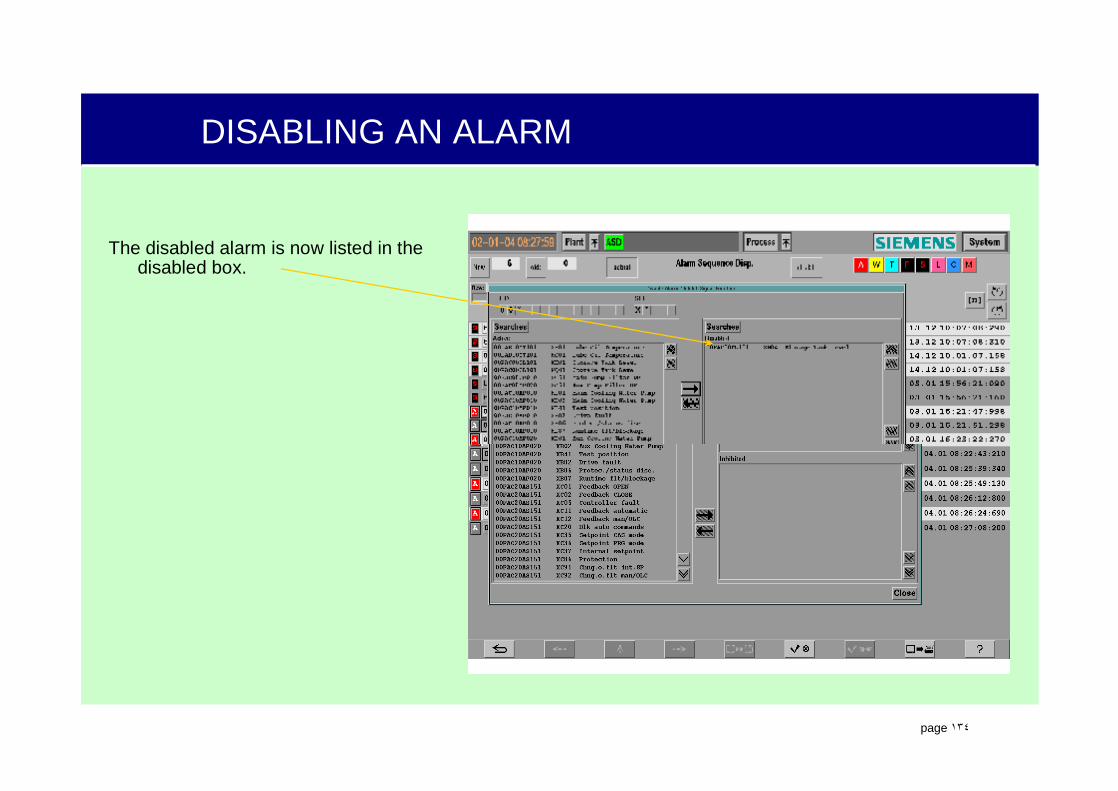
The disabled alarm is now listed in the disabled box.
.
page ١٣٥
SEARCHING FOR AND REENABLING AN ALARM
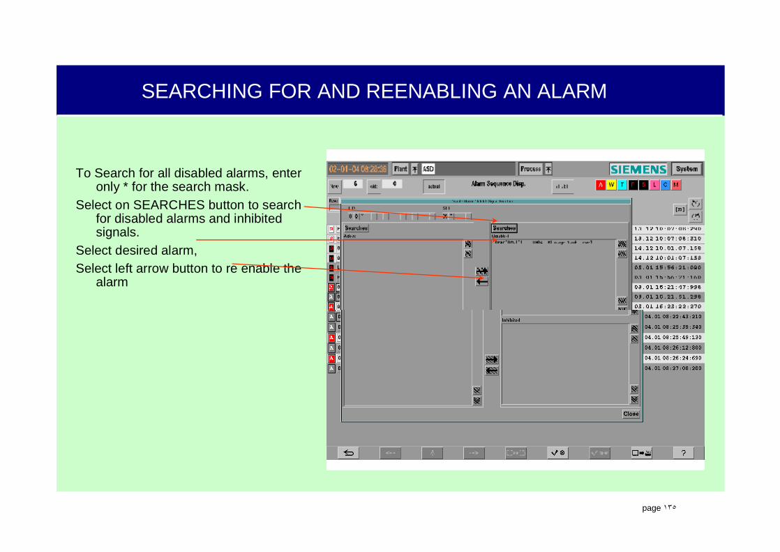
To Search for all disabled alarms, enter only * for the search mask.
Select on SEARCHES button to search for disabled alarms and inhibited signals.
Select desired alarm,Select left arrow button to re enable the
alarm

.
page ١٣٦
PROCESS DISPLAY IN OM650“ON-LINE TRENDS”

.
page ١٣٧
Process Overview Key
PROCESS OVERVIEW DISPLAY (TREND MENU)
.
page ١٣٨
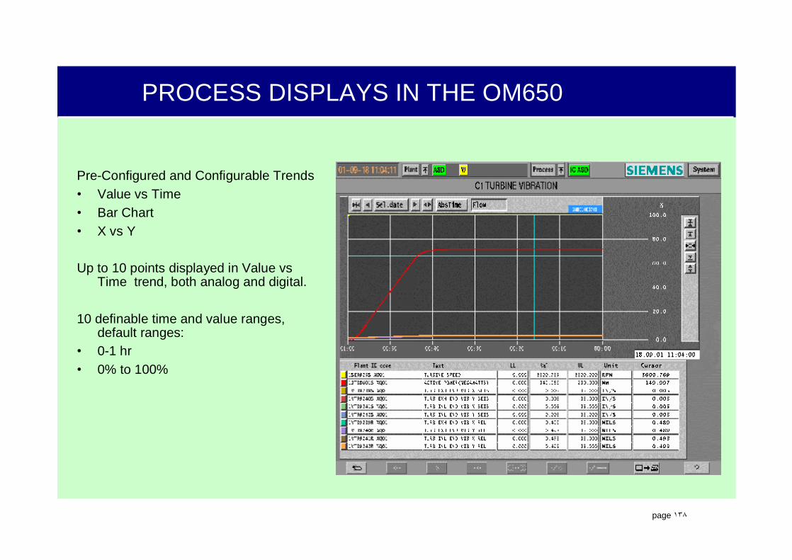
PROCESS DISPLAYS IN THE OM650
Pre-Configured and Configurable Trends• Value vs Time• Bar Chart• X vs Y
Up to 10 points displayed in Value vsTime trend, both analog and digital.
10 definable time and value ranges, default ranges:
• 0-1 hr• 0% to 100%

.
page ١٣٩
TIME SCALE KEY SET
Increase Time Range
Decrease Time Range
Dynamic/Static Flow Key
Absolute/Relative
Time KeyMove Time
Range RightSelect Date
Key
Move TimeRange Left

.
page ١٤٠
Increase ValueRange
Move ValueRange Up
Select Default
SettingsMove Value
Range Down
DecreaseValue Range
VALUE RANGE KEY SET

.
page ١٤١
Value At Curve Start
Parameter Key
Plant ID Code
Plant ID Text
Lower Limit
Value At Cursor
Upper Limit Units
LEGEND
.
page ١٤٢
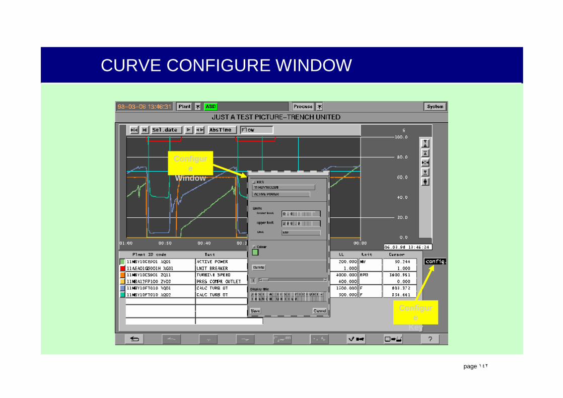
Configure
Key
Configure
Window
CURVE CONFIGURE WINDOW
.
page ١٤٣
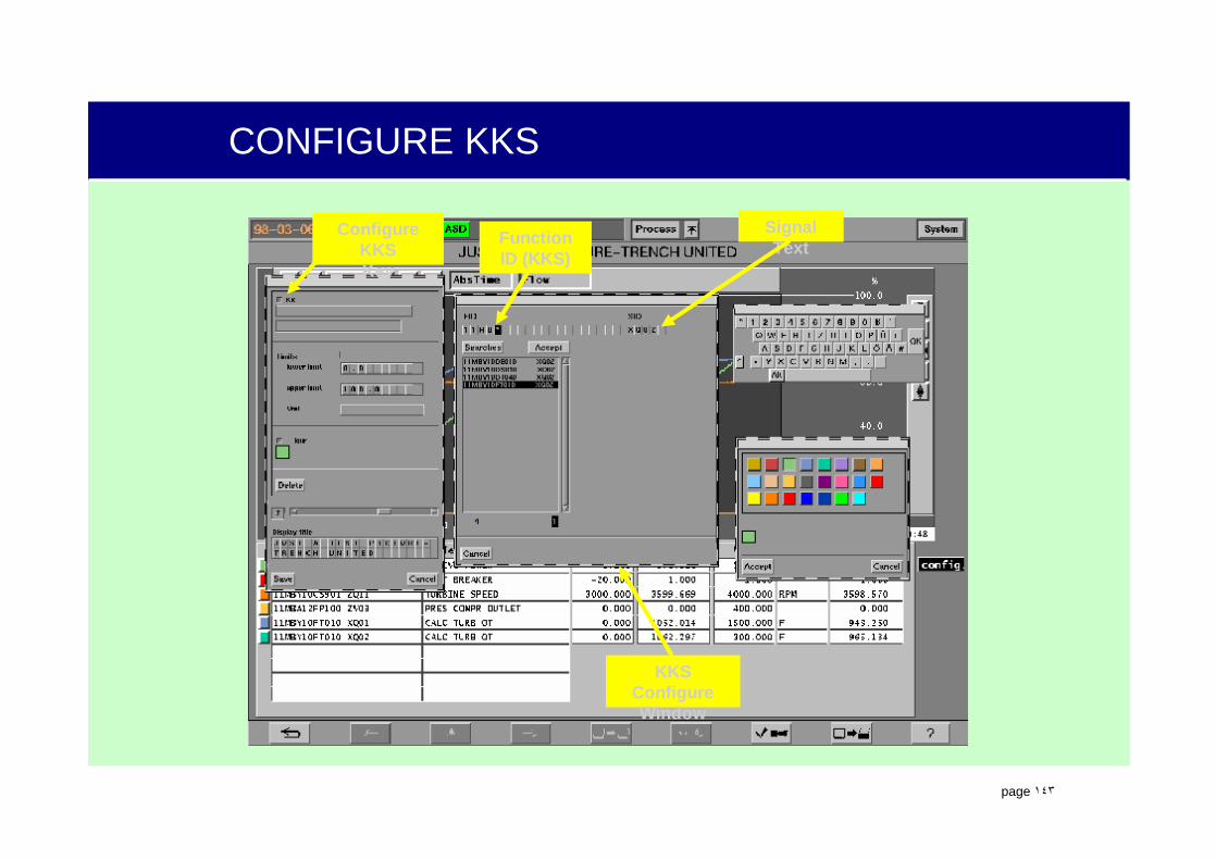
Configure KKSKey
KKS Configure Window
Function ID (KKS)
Signal Text
CONFIGURE KKS
.
page ١٤٤
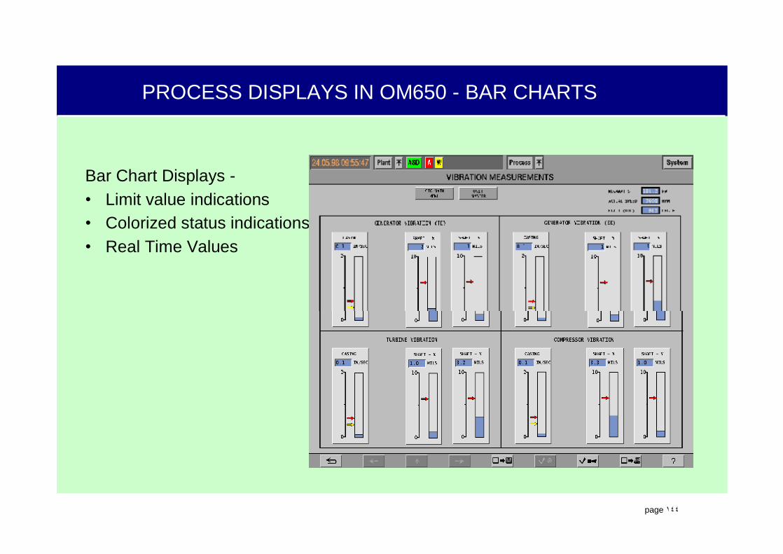
PROCESS DISPLAYS IN OM650 - BAR CHARTS
Bar Chart Displays -• Limit value indications• Colorized status indications• Real Time Values

.
page ١٤٥
ES680: LOGIC/CONTROL OPERATION AND APPLICATIONS

.
page ١٤٦
I&C DOCUMENTATION OVERVIEW
Function-oriented documentation is important to the power plant operator.
The control schemes are described on functional (or logic) diagrams.
Function diagrams are simplified representations which represent the logical circuitry used for the safety, control, processing and monitoring of the power plant.
Function diagrams illustrate the processing of:– Sequencing signals (start-up and shutdown
programs)– Protection signals (alarm and trip)– Supervision signals
.
page ١٤٧
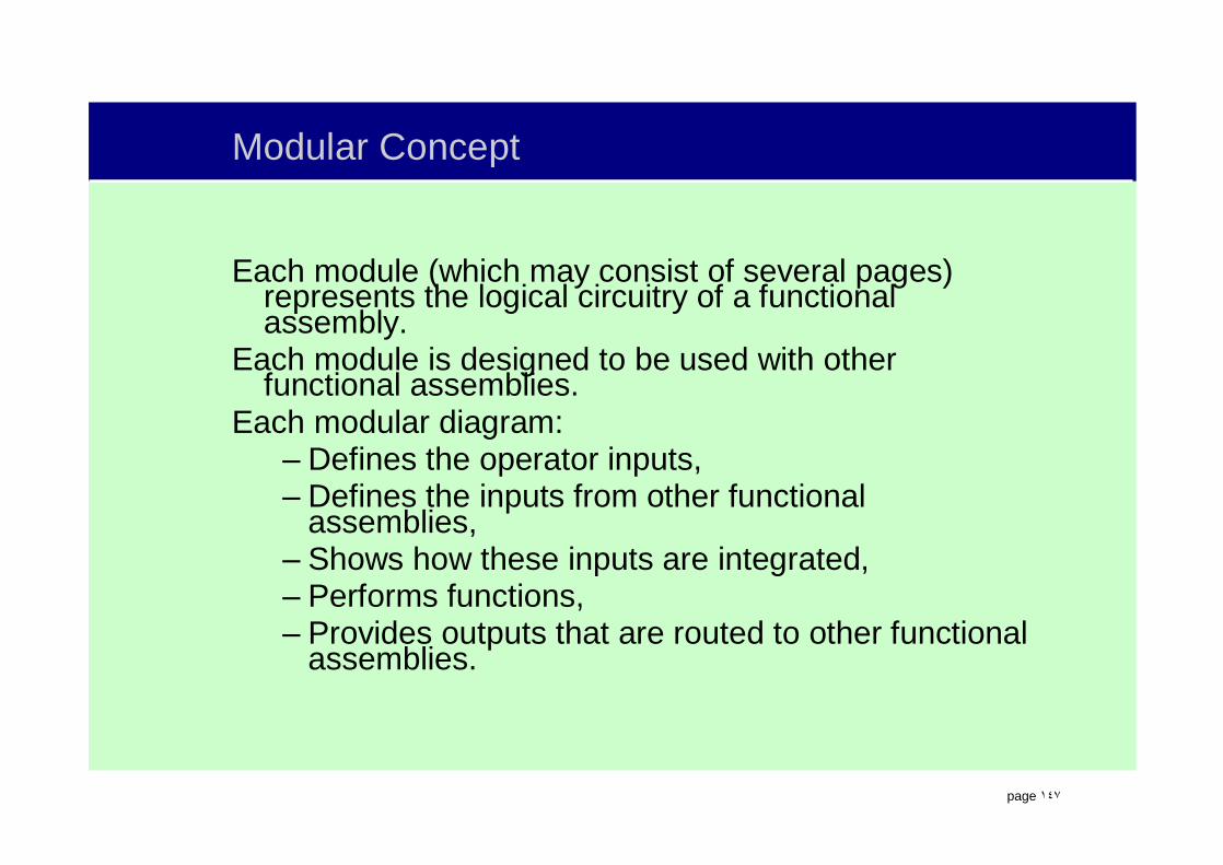
Modular Concept
Each module (which may consist of several pages) represents the logical circuitry of a functional assembly.
Each module is designed to be used with other functional assemblies.
Each modular diagram:– Defines the operator inputs,– Defines the inputs from other functional
assemblies, – Shows how these inputs are integrated, – Performs functions, – Provides outputs that are routed to other functional
assemblies.

.
page ١٤٨
MODULAR CONCEPT
Function diagrams identify: – The operating permissives for devices (motor,
valve, etc.),– The operating permissives for subsystems (lube oil,
turning gear, etc.),– The operating permissives for the power plant.– The conditions required before starting the gas
turbine (Ready to Start).– The operations that must be completed from one
command step before proceeding to the next step.– The conditions that will initiate a turbine trip.

.
page ١٤٩
KRAFTWERKKENNZEICHENSYSTEM
ORPOWER PLANT
IDENTIFICATION SYSTEM
.
page ١٥٠
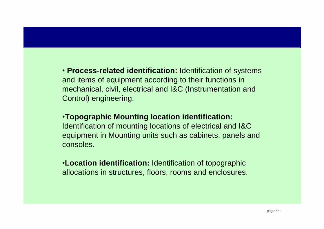
• Process-related identification: Identification of systems and items of equipment according to their functions in mechanical, civil, electrical and I&C (Instrumentation and Control) engineering.
•Topographic Mounting location identification:Identification of mounting locations of electrical and I&C equipment in Mounting units such as cabinets, panels and consoles.
•Location identification: Identification of topographic allocations in structures, floors, rooms and enclosures.

.
page ١٥١
KKS – PROCESS RELATED CODES
lFunction Identification Code (FID) – the unique identification of a component or Function Plan (Logic).
11MBY10CS901.XQ01
lSignal Identification Code (SID) – the unique identification of a signal defined on a Function Plan.

.
page ١٥٢
KKS – PROCESS RELATED CODES
1 2
A N
MBP 00113 AA X -S 01 Typical KKS Number
Component Serial No.
N = Number, A = CharacterAAA NN AA NNN A -A NN
Component Identification CodeEquipment Redundancy (Optional)Equipment Serial No.Equipment Identification CodeSystem Area Serial No.System Identification CodeUnit CodePlant Code

.
page ١٥٣
KKS – PROCESS RELATED CODES – FUNCTION ID
1 2
A N
MBP 00113 AA X -S 01 Typical KKS Number
Component Serial No.Component Identification CodeEquipment Redundancy (Optional)Equipment Serial No.Equipment Identification CodeSystem Area Serial No.System Identification CodeUnit CodePlant Code
N = Number, A = CharacterAAA NN AA NNN A -A NN
PLANT/UNIT CODE UNIT
00 STATION
10 GENERATING UNIT #1, COMMON SYSTEMS
11 GENERATING UNIT #1, GAS TURBINE #1
12 GENERATING UNIT #1, GAS TURBINE #2
20 GENERATING UNIT #2, COMMON SYSTEMS
21 GENERATING UNIT #2, GAS TURBINE #1
22 GENERATING UNIT #2, GAS TURBINE #2
l Plant Code identifies largest grouping of plant equipment. The plant can include multiple generating sets and common systems.
l Unit Code identifies the specific generating unit within the plant.
l A four engine simple cycle site may have a Plant/Unit Code breakdown as shown below.

.
page ١٥٤
KKS – PROCESS RELATED CODES – FUNCTION ID
1 2
A N
MBP 00113 AA X -S 01 Typical KKS Number
Component Serial No.Component Identification CodeEquipment Redundancy (Optional)Equipment Serial No.Equipment Identification CodeSystem Area Serial No.System Identification CodeUnit CodePlant Code
N = Number, A = CharacterAAA NN AA NNN A -A NNl The System ID code is a three letter code
used to identify systems that comprise the power plant.
l The first letter designates major systems or functions and includes:
l M – Main Machine Set
l H – Steam Generating
l E – Fuel delivery
l L – Steam?Water/Gas Cycles
l The second letter identifies the sub group of the major system. Some examples:
l MA – Steam Turbine
l MB – Gas Turbine
l HA – Pressure Systems, both Steam and feedwater.
l The third letter designates the individual system.
l M – Main Machine, B – Gas Turbine, P – Fuel Supply, Gas
.
page ١٥٥
KKS – PROCESS RELATED CODES – FUNCTION ID
1 2
A N
MBP 00113 AA X -S 01 Typical KKS Number
Component Serial No.Component Identification CodeEquipment Redundancy (Optional)Equipment Serial No.Equipment Identification CodeSystem Area Serial No.System Identification CodeUnit CodePlant Code
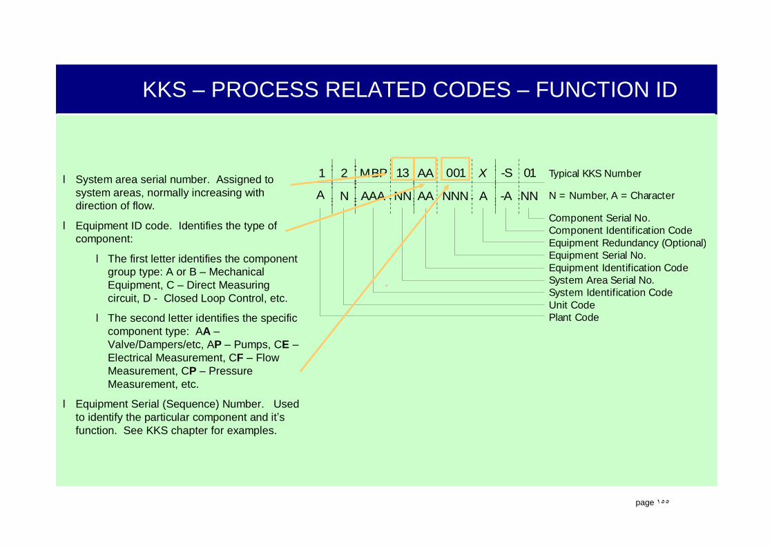
N = Number, A = CharacterAAA NN AA NNN A -A NNl System area serial number. Assigned to
system areas, normally increasing with direction of flow.
l Equipment ID code. Identifies the type of component:
l The first letter identifies the component group type: A or B – Mechanical Equipment, C – Direct Measuring circuit, D - Closed Loop Control, etc.
l The second letter identifies the specific component type: AA –Valve/Dampers/etc, AP – Pumps, CE –Electrical Measurement, CF – Flow Measurement, CP – Pressure Measurement, etc.
l Equipment Serial (Sequence) Number. Used to identify the particular component and it’s function. See KKS chapter for examples.

.
page ١٥٦
KKS – PROCESS RELATED CODES – FUNCTION ID
1 2
A N
MBP 00113 AA X -S 01 Typical KKS Number
Component Serial No.Component Identification CodeEquipment Redundancy (Optional)Equipment Serial No.Equipment Identification CodeSystem Area Serial No.System Identification CodeUnit CodePlant Code
N = Number, A = CharacterAAA NN AA NNN A -A NNl Equipment Redundancy and Component ID –
Optional designation of smaller units on or within a component. Such as a valve’s open or closed limit switches.
l Component Serial Number – unique serial number for smaller units.

.
page ١٥٧
KKS – PROCESS RELATED CODES – SIGNAL ID
l Signal ID Code (SID) identifies a particular signal on a Function Plan (as given by the FID)l First letter identifies the usage of the signal (Origin refers to the source of the signal, Application refers to the destination of
the signal).l X – Identification for an individual signal origin.l Z – Identification for a gated (or composite) signal origin.l Y – Identification for a Signal Application (destination). A signal can have several applications.
l Second letter identifies the type of signal:l XQ – Analog signalsl ZQ – Analog signal that has been modified – an XQ turbine speed in RPM converted to a ZQ turbine speed in Hz.l XS – Functional Group Control step signalsl XH - Binary Limit Signal that is derived from an Analog Process signal.l ZV – Signal Gating, such as protective or alarm logic signalsl YP – Supervisory Control Destination, such as the Alarm Processing Area of the OM650.
l Last two numbers are the serialized identification of the unique signals.l There are more rules and specific definitions for SID’s when using function blocks. See KKS definitions for specific rules.
For example:l XA41 and XA42 are the “Checkback On” and “Checkback Off” signals from a SLC.l XB01 is the DCM command signal to turn on (or open) a pump (valve).
11MBY10CS901.XQ01

.
page ١٥٨
TXP LOGIC OVERVIEW
• Functional Plan (FUP) documentation is important to the power plant operator and is part of the technical plant documentation.
• FUPs allow the operator to fully understand the control of the plant components.

.
page ١٥٩
TXP LOGIC OVERVIEW
Function diagrams are a type of functional plan. (YFRs)
Function diagrams are simplified representations which represent the logical circuitry used for the safety, control, processing and monitoring of the power plant.
.
page ١٦٠
TXP LOGIC OVERVIEW
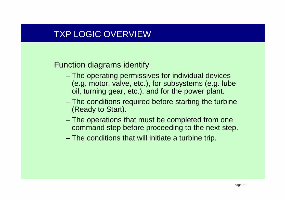
Function diagrams identify: – The operating permissives for individual devices
(e.g. motor, valve, etc.), for subsystems (e.g. lube oil, turning gear, etc.), and for the power plant.
– The conditions required before starting the turbine (Ready to Start).
– The operations that must be completed from one command step before proceeding to the next step.
– The conditions that will initiate a turbine trip.

.
page ١٦١
TXP LOGIC OVERVIEW
Organized in a hierarchicalstructure.
• overview level (YFH)• area level (YFM)• single-loop level (YFR). Each level of the hierarchy
represents diagrams of greater detail.
OverviewLevel(YFH)
AreaLevel(YFM)
IndividualLevel(YFR)

.
page ١٦٢
TXP LOGIC OVERVIEW
• YFR is subdivided into three sections; inputs, functions and outputs.
Presentationof Functions
Tabulator Section
Text Field
Tabulator Section
Signal OutputsSignal Inputs

.
page ١٦٣
TXP LOGIC OVERVIEW
XB02off
XA21equi1 onXS53
XH54OPTDXH03HIHI
DB 93D 208.1
SIGDEFSIGDEF
XB01/Z1
XB02/Z1
> 1
&
&
10 s 0
XA01/2
-
1
XB95/Z1
OM
PON
ENON
OON
channel 1
1
BLAP
OOFF
ENOFF
POFF
CBOFF
DCMmotor/solenoid valve
CBON
OM
DB 90D 17.0
DB 90D 15.15
DB 90D 15.12
DB 90D 15.13
7 0PGC40 EE001AUX CW PMPS
ZV01
XH04NOT LO
XH01on
DB 90D 1.11
DB 93D 114.1
DB 90D 15.9
7 0LAC11 CP001EFP A OIL P
7 0LAC20 AP001EFP B MTR
7 0LAC20 AP001EFP B MTR
7 0LAC00 EC001EFP A & B7 0LAB00 EC001Feedwater System
7 0LAB41 CP901EFP A NPSH PROTECTION7 0LAC10 CT001EFP A MTR NDE BRG T
XB95 SIGDEFEFP A MTR
SignalFlowInputs
Outputs
.
page ١٦٤
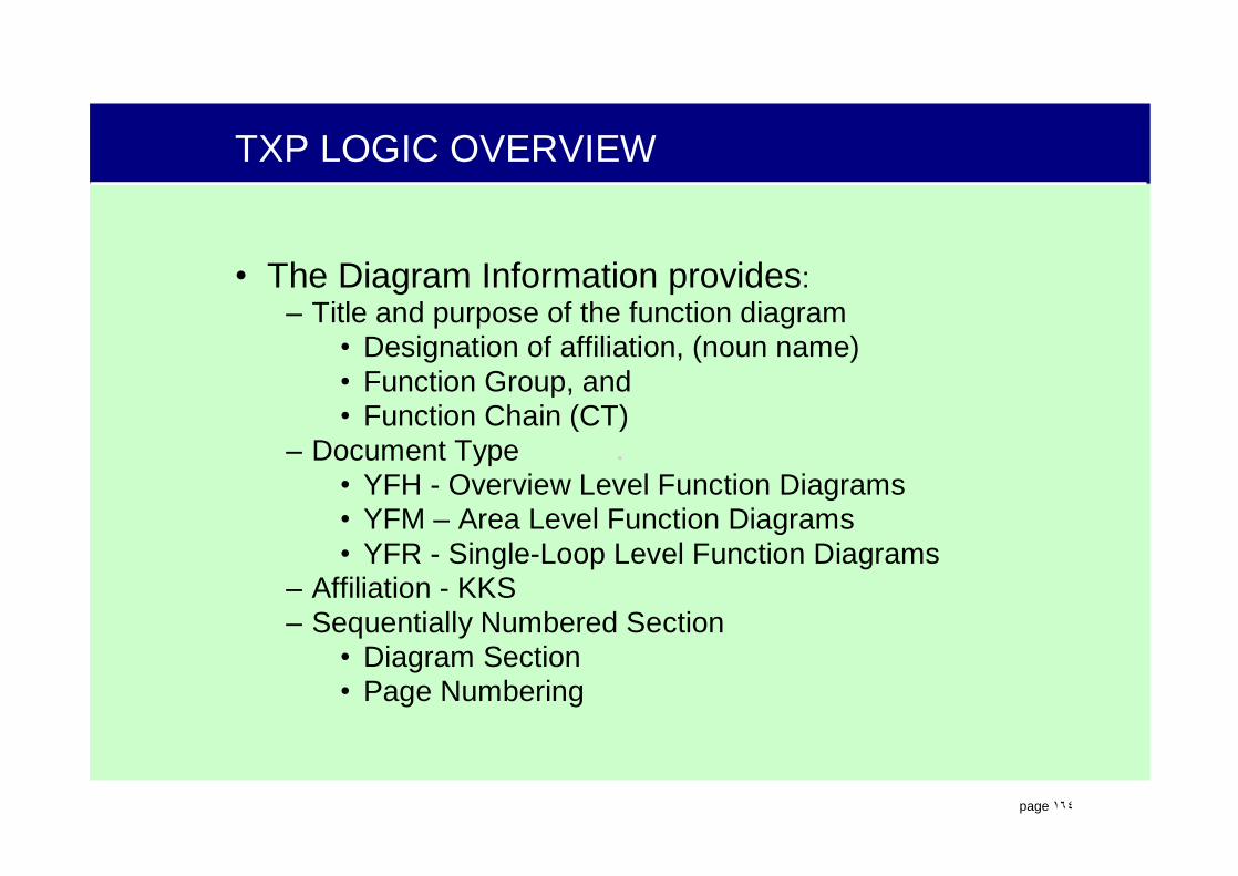
TXP LOGIC OVERVIEW
• The Diagram Information provides:– Title and purpose of the function diagram
• Designation of affiliation, (noun name)• Function Group, and• Function Chain (CT)
– Document Type• YFH - Overview Level Function Diagrams• YFM – Area Level Function Diagrams• YFR - Single-Loop Level Function Diagrams
– Affiliation - KKS– Sequentially Numbered Section
• Diagram Section • Page Numbering

.
page ١٦٥
TXP LOGIC OVERVIEW
Designation of affiliation
5Page 1
B001= 11MBV21AP001YFRFC GTYGTA00
Stat. Modification Date Name Stand. Orig./Repl.f/Repl. byCheckDrawn
GAS TURBINE SIMULATORTRAINING CENTEROFFENBACH
Date
MAIN LUBE OIL PUMP
Function Group
PROJECT INFORMATION DIAGRAM INFORMATION
Function ChainDocument Type
Affiliation
Siemens AGFunctional diagram individual level Sh.

.
page ١٦٦
TXP LOGIC OVERVIEW
• On the input signal side each signal provides;– KKS (12MBV20CT003B),– FGC (XMBV00)– Designation (Lube Oil Supply Temp #2), – Signal Identification (XQ01)– Setting (0 to 250)– Unit of measure (C)

.
page ١٦٧
TXP LOGIC OVERVIEW
• On the signal output side each signal provides;– Signal Identification (ZQ01)– KKS (12MBX71AA183),– Designation (Lube Cooler Temp Control Valve),– Setting (0 to 250)– Unit of measure (C)

.
page ١٦٨
TXP LOGIC OVERVIEW
Tracing signals within a single process-related identification area.
Siemens AG SLC OIL CIRCULATIONFUNCTION CHART
YFR = MBV21EE010
XN02SLC OIL CIRCULATION
CKAA01GK300PRINTER
T003
S02 N OFFK YP50
Sh.No.
&
1
Signalfrom
page no.
Connector
B / T001
“B” - Connector (like signal name), “T001” - Page number (where signal came from)

.
page ١٦٩
TXP LOGIC OVERVIEWTracing signals within
a single process-related identification area.
Siemens AG SLC OIL CIRCULATIONFUNCTION CHART
YFR = MBV21EE010
XA42SLC OIL CIRCULATION
SLC OIL CIRCULATION
MYB01EC001
MBV21EU002U001
M003SGC GAS TURBINE
T001
OFFYV
YV
Sh.No.
Signalto
page no.Connector
B / T003
“B” - Connector (like signal name), “T003” - Page number (where signal is going to)
.
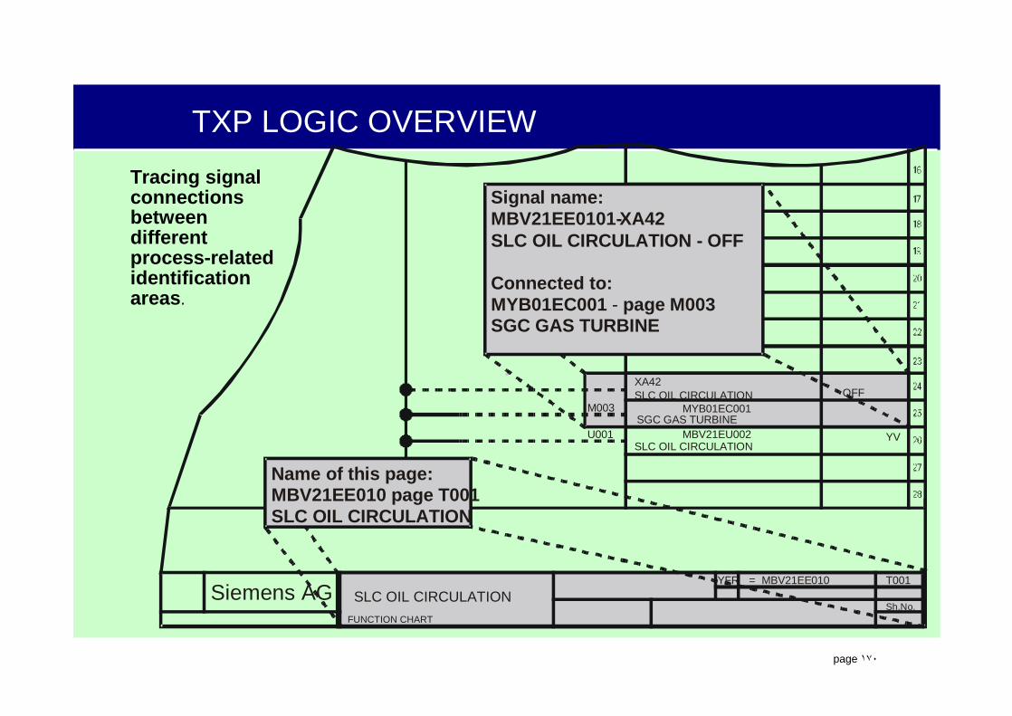
page ١٧٠
TXP LOGIC OVERVIEWTracing signal connections between different process-related identificationareas.
Siemens AG SLC OIL CIRCULATIONFUNCTION CHART
YFR = MBV21EE010
XA42SLC OIL CIRCULATION
Signal name:MBV21EE0101-XA42SLC OIL CIRCULATION - OFF
Connected to:MYB01EC001 - page M003SGC GAS TURBINE
Name of this page:MBV21EE010 page T001SLC OIL CIRCULATION
SLC OIL CIRCULATION
MYB01EC001
MBV21EU002U001
M003SGC GAS TURBINE
T001
OFF
YV
Sh.No.
.
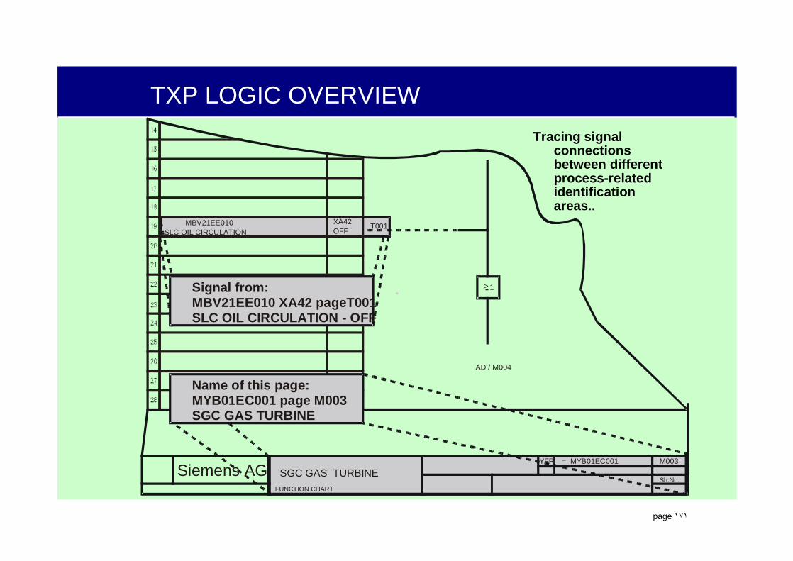
page ١٧١
TXP LOGIC OVERVIEWTracing signal
connections between different process-related identification areas..
Siemens AG SGC GAS TURBINEFUNCTION CHART
YFR = MYB01EC001 M003
Sh.No.
MBV21EE010SLC OIL CIRCULATION
XA42OFF
T001
AD / M004
> 1
Name of this page:MYB01EC001 page M003SGC GAS TURBINE
Signal from:MBV21EE010 XA42 pageT001SLC OIL CIRCULATION - OFF
.
page ١٧٢
GATE LOGIC
Gate logic is used to perform basic process and algebraic functions on signals.
.
page ١٧٣
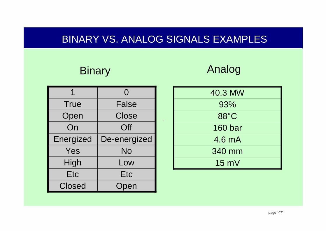
BINARY VS. ANALOG SIGNALS EXAMPLES
Binary
OpenClosedEtcEtcLowHighNoYes
De-energizedEnergizedOffOn
CloseOpenFalseTrue
01
15 mV340 mm4.6 mA160 bar
88°C93%
40.3 MW
Analog
.
page ١٧٤
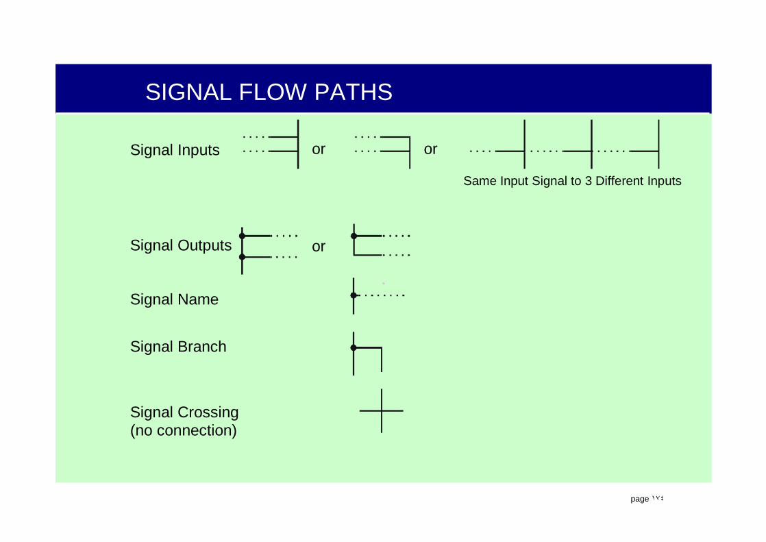
SIGNAL FLOW PATHS
Signal Crossing(no connection)
Signal Name
Signal Outputs or
Signal Branch
Signal Inputs or or
Same Input Signal to 3 Different Inputs
.
page ١٧٥
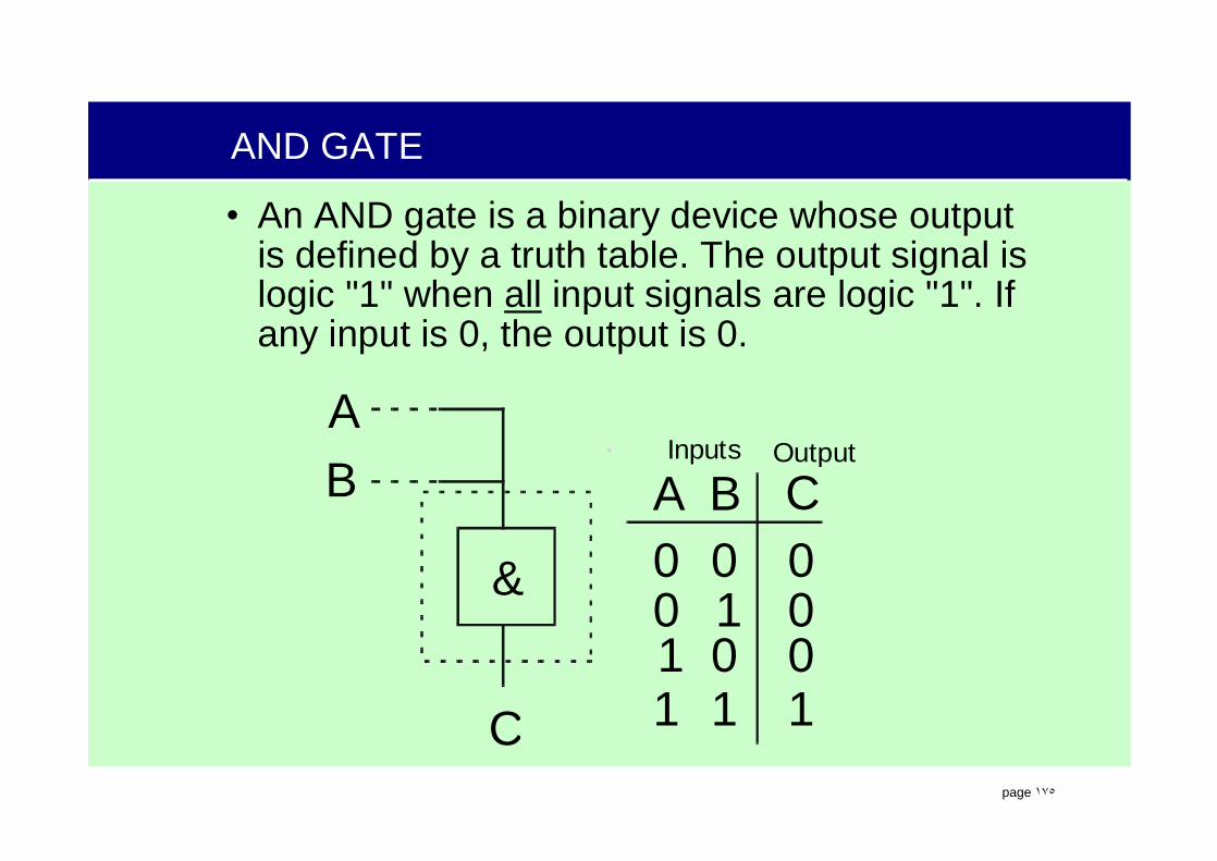
AND GATE
• An AND gate is a binary device whose output is defined by a truth table. The output signal is logic "1" when all input signals are logic "1". If any input is 0, the output is 0.
& 00
1
0
01
0001
11
A
AInputs Output
BB C
C

.
page ١٧٦
OR GATE
• An OR gate is a binary device whose output is defined by a truth table. The output signal is logic "1" if any input signals are logic "1". If allinputs are 0, the output is 0.
>1 00
1
0
01
0111
11
A
AInputs Output
BB C
C

.
page ١٧٧
EXCLUSIVE OR GATE
• An Exclusive OR gate is a binary device whose output is defined by a truth table. The output signal is logic "1" if and only if one input signal is a logic "1". If all inputs are 0, or more than 1 input is a logic “1” the output is 0.
.
page ١٧٨
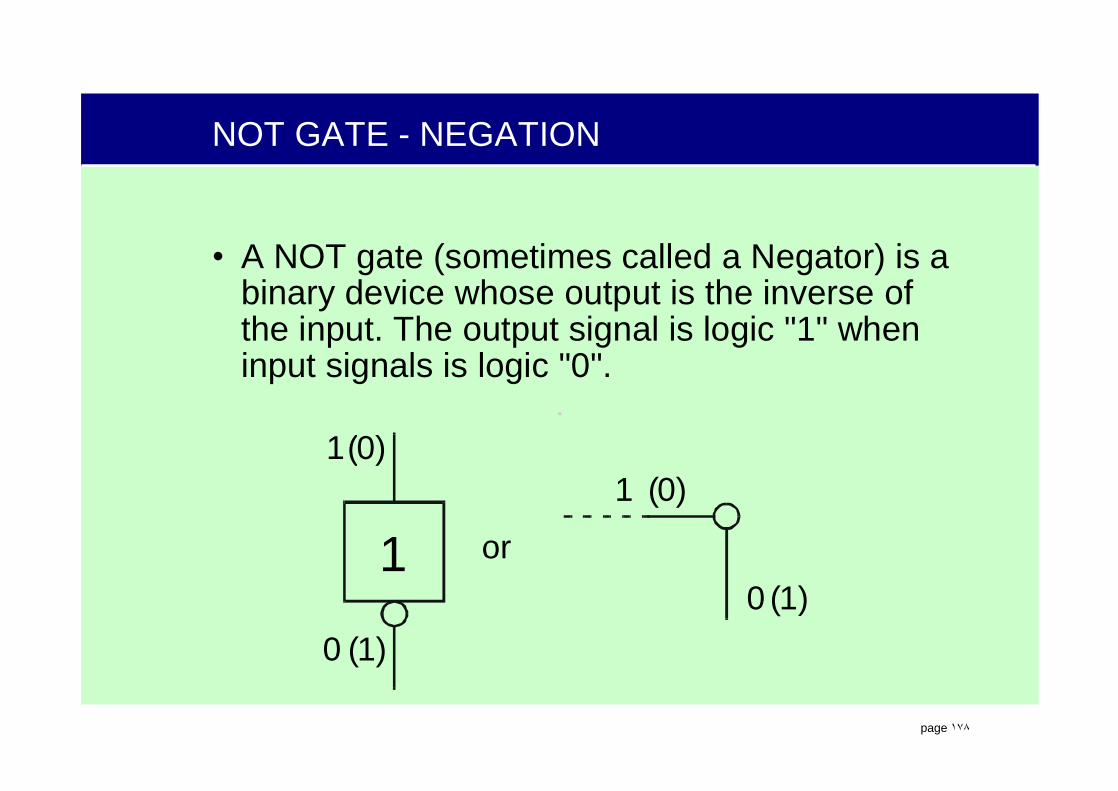
NOT GATE - NEGATION
• A NOT gate (sometimes called a Negator) is a binary device whose output is the inverse of the input. The output signal is logic "1" when input signals is logic "0".
1 or
11
00
(0)(0)
(1)(1)

.
page ١٧٩
Sub Loop Controller
• A Sub Loop Controller is used to keep defined process states. Functions like a RS flip flop.
• Automatic controls can “block” operator input by placing a “1” on BLOM input
• Priorities are:– Automatic “OFF”– Automatic “ON”– Manual “ON/OFF”
SLC
AON
OM
CBON
CBOFF
AOFF
BLOM
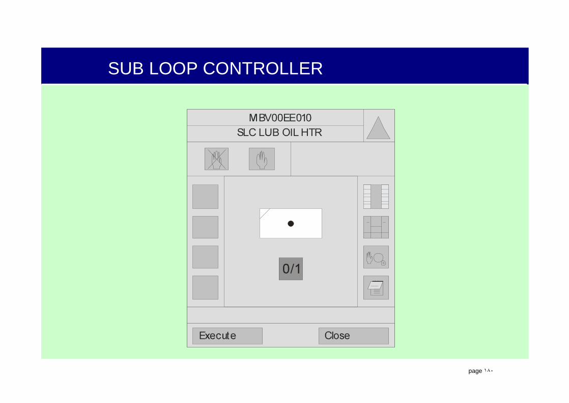
.
page ١٨٠
SUB LOOP CONTROLLER

.
page ١٨١
SUB LOOP CONTROLLER
SLC
AON
OM
CBON
CBOFF
AOFF
BLOM
INPUT SIGNALS:
OUTPUT SIGNALS:CB-OFF -Checkback off
A-ON -Automatic on
CB-ON -Checkback on
A-OFF -Automatic off
OTHER SIGNALS:OM -Operating / Monitoring
BLOM -Block OM
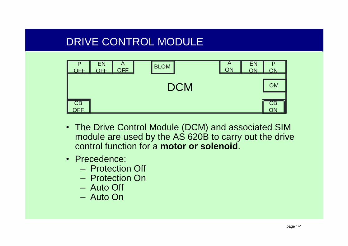
.
page ١٨٢
DRIVE CONTROL MODULE
• The Drive Control Module (DCM) and associated SIM module are used by the AS 620B to carry out the drive control function for a motor or solenoid.
• Precedence:– Protection Off– Protection On– Auto Off– Auto On
DCM
AON
AOFF
ENOFF
ENON
PON
POFF
OM
CBOFF
CBON
BLOM

.
page ١٨٣
DRIVE CONTROL MODULE
Execute Close
Notebook
Selection/Deselectionof Window Extension 2
Open theDetail Window
Function DiagramSelection 1
Enable
Disenable
Selection of Window Extension 1
MAIN LUBE OIL PUMPMBV21AP001
0 1
M

.
page ١٨٤
DRIVE CONTROL MODULE
P-OFF -Protection off
A-ON -Automatic on
EN-OFF -Release off
EN-ON -Release on
A-OFF -Automatic off
P-ON -Protection on
CB-OFF -Checkback offCB-ON -Checkback on
OTHER SIGNALS:OM -Operating / Monitoring
BLOM -Block OMBLAP -Block AP
DCM
AON
AOFF
ENOFF
ENON
PON
POFF
OM
CBOFF
CBON
BLOM BLAP

.
page ١٨٥
DRIVE CONTROL MODULEAuto Off
DCM
AON
AOFF
ENOFF
ENON
PON
POFF
OM
CBOFF
CBON
1
0 11 X 0X
0
X means it does not matter if it is a 1 or 0

.
page ١٨٦
DRIVE CONTROL MODULE
Protection Off
DCM
AON
AOFF
ENOFF
ENON
PON
POFF
OM
CBOFF
CBON
1
1 XX X XX
0
X means it does not matter if it is a 1 or 0
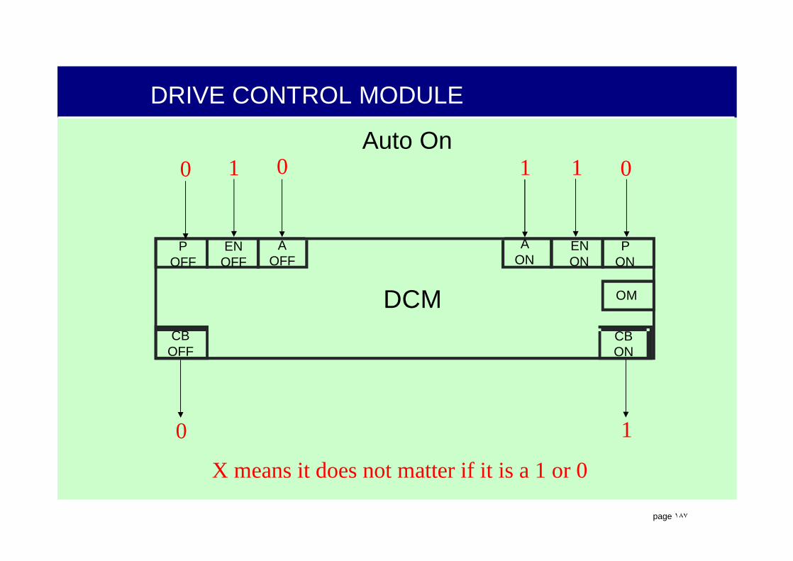
.
page ١٨٧
DRIVE CONTROL MODULE
Auto On
DCM
AON
AOFF
ENOFF
ENON
PON
POFF
OM
CBOFF
CBON
0 1
0 01 1 01
X means it does not matter if it is a 1 or 0
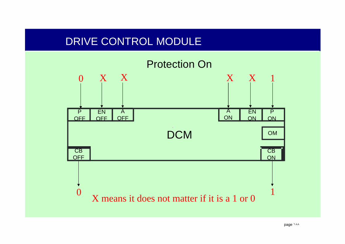
.
page ١٨٨
DRIVE CONTROL MODULE
Protection On
DCM
AON
AOFF
ENOFF
ENON
PON
POFF
OM
CBOFF
CBON
0
0 XX X 1X
1X means it does not matter if it is a 1 or 0

.
page ١٨٩
DRIVE CONTROL MODULE

.
page ١٩٠
SUB GROUP CONTROLLER (SGC)
SGC
AOPER
ENOPER
OM
SDAOPER
CBOPER
ASTIL
ENSTIL
AOFF
CBSTIL
SDASTIL
AON
PROGSTIL
CBSTIL
STEPSTIL
CBON
STEPOPER
PROGOPER
CBOPER
CB AOFF
CBRTA
• The Sub Group Controller (SGC) is used to automate large processes such as:
– System or Turbine Startups– System or Turbine Shutdowns– System Test functions
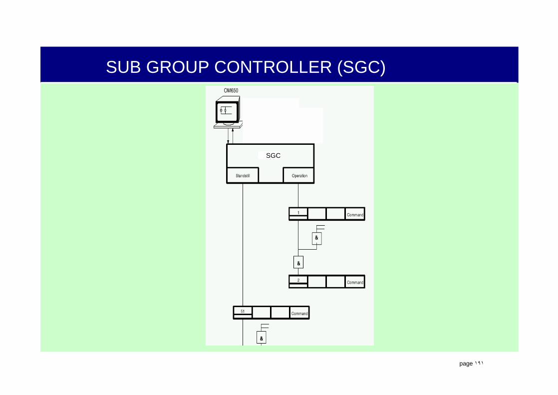
.
page ١٩١
SUB GROUP CONTROLLER (SGC)
SGC
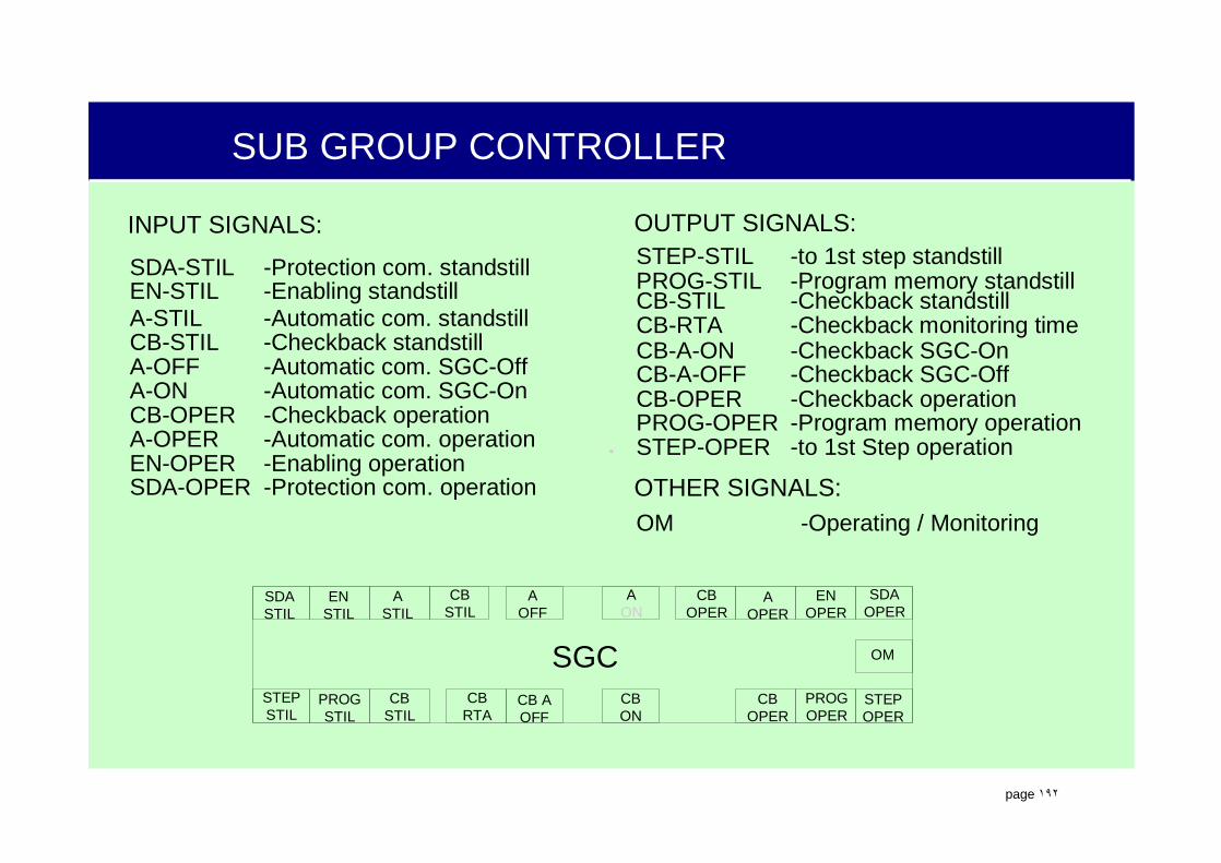
.
page ١٩٢
SUB GROUP CONTROLLER
INPUT SIGNALS: OUTPUT SIGNALS:
A-STILCB-STIL
SDA-STIL STEP-STIL
CB-A-ON-Automatic com. standstill
-Checkback standstill-Protection com. standstill -to 1st step standstill
-Checkback SGC-On
A-ON -Automatic com. SGC-On
CB-STILCB-RTA
EN-STIL PROG-STIL
CB-A-OFF-Checkback standstill
-Checkback monitoring time-Enabling standstill -Program memory standstill
-Checkback SGC-Off
CB-OPER
EN-OPER
PROG-OPER-Checkback operation
-Enabling operation
-Program memory operation
A-OFF -Automatic com. SGC-Off
A-OPER
CB-OPER
SDA-OPER
STEP-OPER-Automatic com. operation
-Checkback operation
-Protection com. operation
-to 1st Step operation
OTHER SIGNALS:OM -Operating / Monitoring
SGC
AOPER
ENOPER
OM
SDAOPER
CBOPER
ASTIL
ENSTIL
AOFF
CBSTIL
SDASTIL
AON
PROGSTIL
CBSTIL
STEPSTIL
CBON
STEPOPER
PROGOPER
CBOPER
CB AOFF
CBRTA
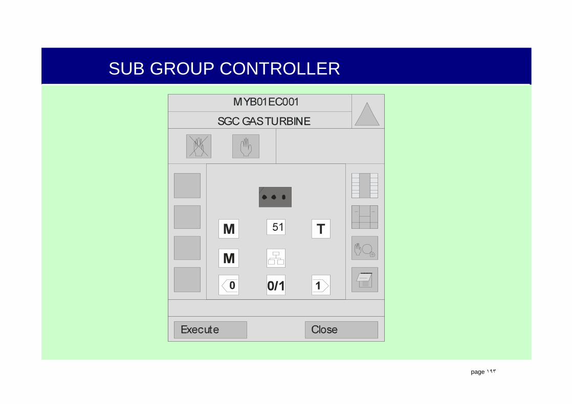
.
page ١٩٣
SUB GROUP CONTROLLER
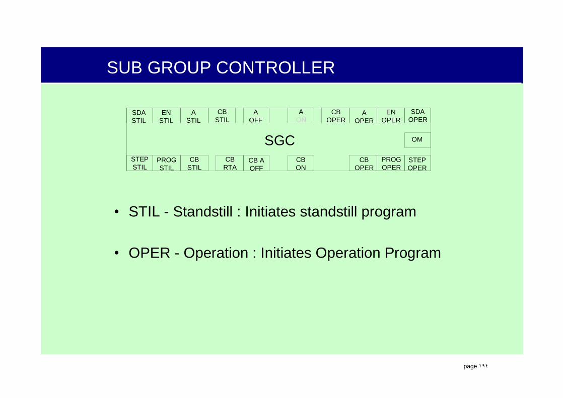
.
page ١٩٤
SUB GROUP CONTROLLER
SGC
AOPER
ENOPER
OM
SDAOPER
CBOPER
ASTIL
ENSTIL
AOFF
CBSTIL
SDASTIL
AON
PROGSTIL
CBSTIL
STEPSTIL
CBON
STEPOPER
PROGOPER
CBOPER
CB AOFF
CBRTA
• STIL - Standstill : Initiates standstill program
• OPER - Operation : Initiates Operation Program
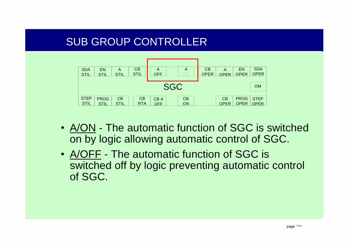
.
page ١٩٥
SUB GROUP CONTROLLER
SGC
AOPER
ENOPER
OM
SDAOPER
CBOPER
ASTIL
ENSTIL
AOFF
CBSTIL
SDASTIL
AON
PROGSTIL
CBSTIL
STEPSTIL
CBON
STEPOPER
PROGOPER
CBOPER
CB AOFF
CBRTA
• A/ON - The automatic function of SGC is switched on by logic allowing automatic control of SGC.
• A/OFF - The automatic function of SGC is switched off by logic preventing automatic control of SGC.
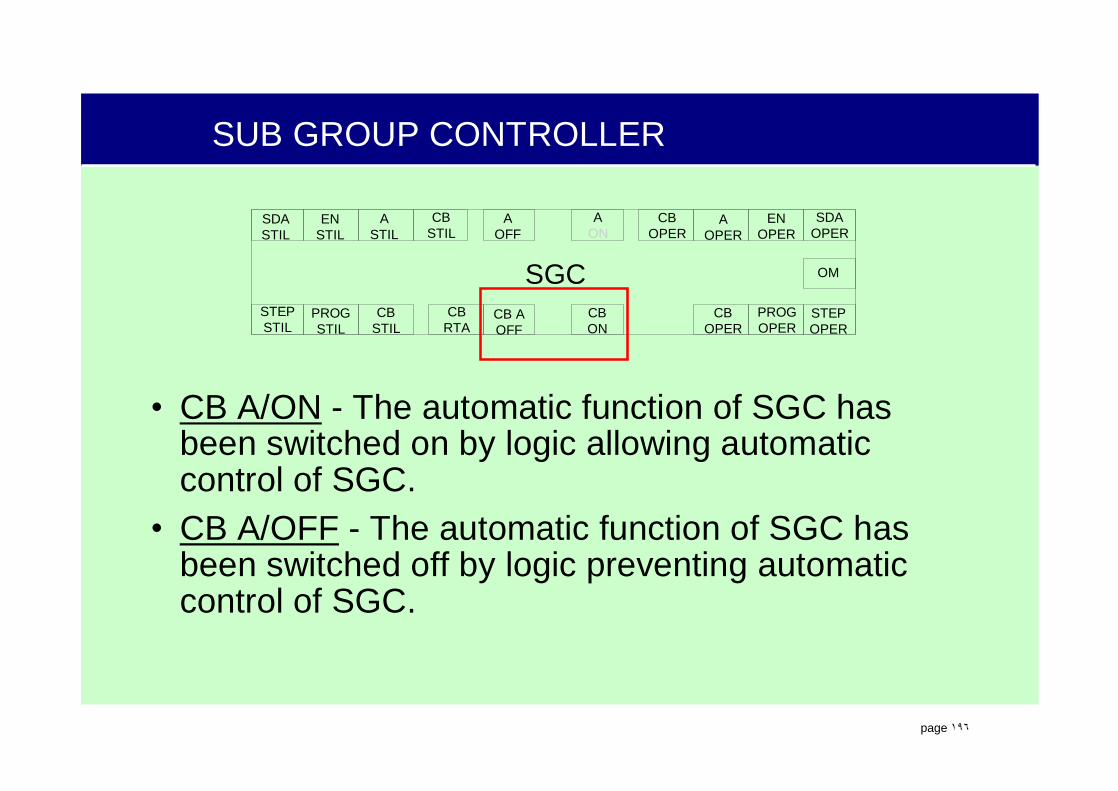
.
page ١٩٦
SUB GROUP CONTROLLER
• CB A/ON - The automatic function of SGC has been switched on by logic allowing automatic control of SGC.
• CB A/OFF - The automatic function of SGC has been switched off by logic preventing automatic control of SGC.
SGC
AOPER
ENOPER
OM
SDAOPER
CBOPER
ASTIL
ENSTIL
AOFF
CBSTIL
SDASTIL
AON
PROGSTIL
CBSTIL
STEPSTIL
CBON
STEPOPER
PROGOPER
CBOPER
CB AOFF
CBRTA
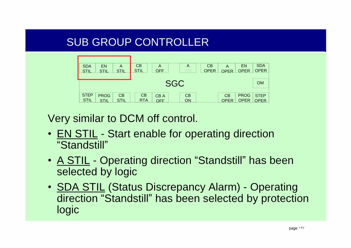
.
page ١٩٧
SUB GROUP CONTROLLER
Very similar to DCM off control.• EN STIL - Start enable for operating direction “Standstill”
• A STIL - Operating direction “Standstill” has been selected by logic
• SDA STIL (Status Discrepancy Alarm) - Operating direction “Standstill” has been selected by protection logic
SGC
AOPER
ENOPER
OM
SDAOPER
CBOPER
ASTIL
ENSTIL
AOFF
CBSTIL
SDASTIL
AON
PROGSTIL
CBSTIL
STEPSTIL
CBON
STEPOPER
PROGOPER
CBOPER
CB AOFF
CBRTA

.
page ١٩٨
SUB GROUP CONTROLLER
SGC
AOPER
ENOPER
OM
SDAOPER
CBOPER
ASTIL
ENSTIL
AOFF
CBSTIL
SDASTIL
AON
PROGSTIL
CBSTIL
STEPSTIL
CBON
STEPOPER
PROGOPER
CBOPER
CB AOFF
CBRTA
• STEP STIL - Start signal for operating direction “Standstill” to begin step 51
• PROG STIL - Steps in the operating direction “Standstill” are in progress
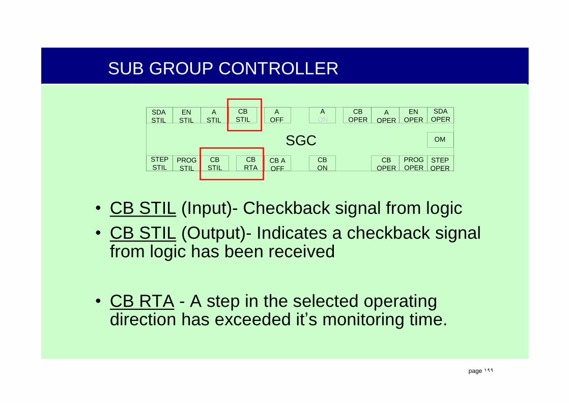
.
page ١٩٩
SUB GROUP CONTROLLER
• CB STIL (Input)- Checkback signal from logic• CB STIL (Output)- Indicates a checkback signal
from logic has been received
• CB RTA - A step in the selected operating direction has exceeded it’s monitoring time.
SGC
AOPER
ENOPER
OM
SDAOPER
CBOPER
ASTIL
ENSTIL
AOFF
CBSTIL
SDASTIL
AON
PROGSTIL
CBSTIL
STEPSTIL
CBON
STEPOPER
PROGOPER
CBOPER
CB AOFF
CBRTA

.
page ٢٠٠
SUB GROUP CONTROLLER
Very similar to DCM on control.• EN OPER - Start enable for operating direction “Operation”
• A OPER - Operating direction “Operation” has been selected by logic
• SDA OPER (Status Discrepancy Alarm) -Operating direction “Operation” has been selected by protection logic
SGC
AOPER
ENOPER
OM
SDAOPER
CBOPER
ASTIL
ENSTIL
AOFF
CBSTIL
SDASTIL
AON
PROGSTIL
CBSTIL
STEPSTIL
CBON
STEPOPER
PROGOPER
CBOPER
CB AOFF
CBRTA

.
page ٢٠١
SUB GROUP CONTROLLER
• STEP OPER - Start signal for operating direction “Operation” to begin step 1
• PROG OPER - Steps in the operating direction “Operation” are in progress
SGC
AOPER
ENOPER
OM
SDAOPER
CBOPER
ASTIL
ENSTIL
AOFF
CBSTIL
SDASTIL
AON
PROGSTIL
CBSTIL
STEPSTIL
CBON
STEPOPER
PROGOPER
CBOPER
CB AOFF
CBRTA

.
page ٢٠٢
SUB GROUP CONTROLLER
• CB OPER (Input)- Checkback signal from logic• CB OPER (Output)- Indicates a checkback signal
from logic has been received• CB RTA - A step in the selected operating direction
has exceeded it’s monitoring time. Same output used for both operating directions
SGC
AOPER
ENOPER
OM
SDAOPER
CBOPER
ASTIL
ENSTIL
AOFF
CBSTIL
SDASTIL
AON
PROGSTIL
CBSTIL
STEPSTIL
CBON
STEPOPER
PROGOPER
CBOPER
CB AOFF
CBRTA

.
page ٢٠٣
SGC STEP SYMBOL
AlternativeBypass
FromPrevious Logic
From Previous Step
ToNext Step
CommandOutput
&Mo - TimeWaiting timeStep No.tue: 25stw: 20s51 1
Command
ToFollow-on Logic
• The individual steps of a subgroup control are each programmed in individual blocks called step/program blocks.
• Step/program blocks include step number, wait times, monitoring times, enabling steps and commands.

.
page ٢٠٤
SGC STEP SYMBOL
AlternativeBypass
FromPrevious Logic
From Previous Step
ToNext Step
CommandOutput
&Mo - TimeWaiting timeStep No.tue: 25stw: 20s51 1
Command
ToFollow-on Logic
• Step numbers tell the operator what step of the program the SGC is on.
• In general, steps 1 - 50 are used for the operation direction (startups) and steps 51 - 99 are used for the standstill direction (shutdown)
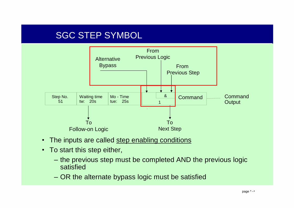
.
page ٢٠٥
SGC STEP SYMBOL
AlternativeBypass
FromPrevious Logic
From Previous Step
ToNext Step
CommandOutput
&Mo - TimeWaiting timeStep No.tue: 25stw: 20s51 1
Command
ToFollow-on Logic
• The inputs are called step enabling conditions• To start this step either,
– the previous step must be completed AND the previous logic satisfied
– OR the alternate bypass logic must be satisfied
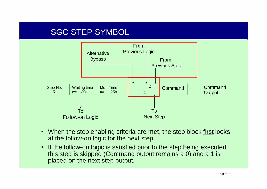
.
page ٢٠٦
SGC STEP SYMBOL
AlternativeBypass
FromPrevious Logic
From Previous Step
ToNext Step
CommandOutput
&Mo - TimeWaiting timeStep No.tue: 25stw: 20s51 1
Command
ToFollow-on Logic
• When the step enabling criteria are met, the step block first looks at the follow-on logic for the next step.
• If the follow-on logic is satisfied prior to the step being executed, this step is skipped (Command output remains a 0) and a 1 is placed on the next step output.

.
page ٢٠٧
SGC STEP SYMBOL
Previous logic satisfied Step 3 complete

.
page ٢٠٨
SGC STEP SYMBOL
If this logic is satisfied priorto sending command output from step 4, step 4 is skipped.

.
page ٢٠٩
SGC STEP SYMBOL
AlternativeBypass
FromPrevious Logic
From Previous Step
ToNext Step
CommandOutput
&Mo - TimeWaiting timeStep No.tue: 25stw: 20s51 1
Command
ToFollow-on Logic
• If the enabling criteria is satisfied and the follow-on logic is not satisfied, a 1 is placed on the command output.
• When the next step is executed, the 1 is replaced with a 0.
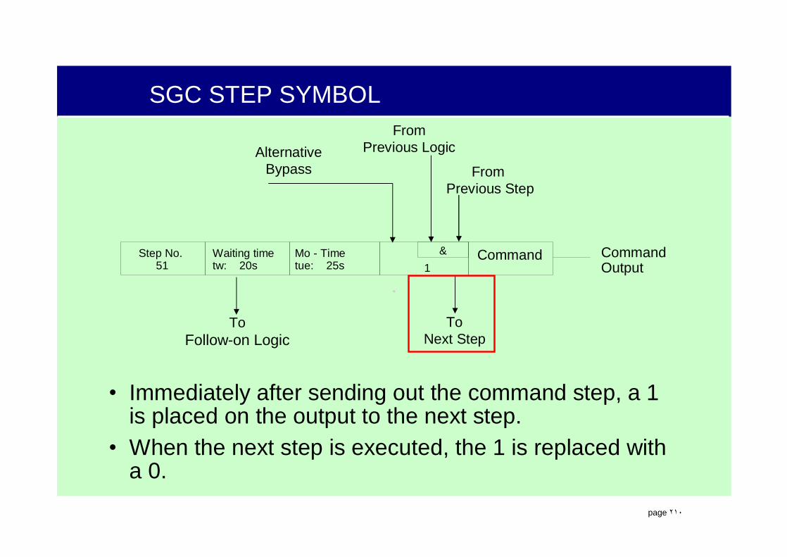
.
page ٢١٠
SGC STEP SYMBOL
AlternativeBypass
FromPrevious Logic
From Previous Step
ToNext Step
CommandOutput
&Mo - TimeWaiting timeStep No.tue: 25stw: 20s51 1
Command
ToFollow-on Logic
• Immediately after sending out the command step, a 1 is placed on the output to the next step.
• When the next step is executed, the 1 is replaced with a 0.
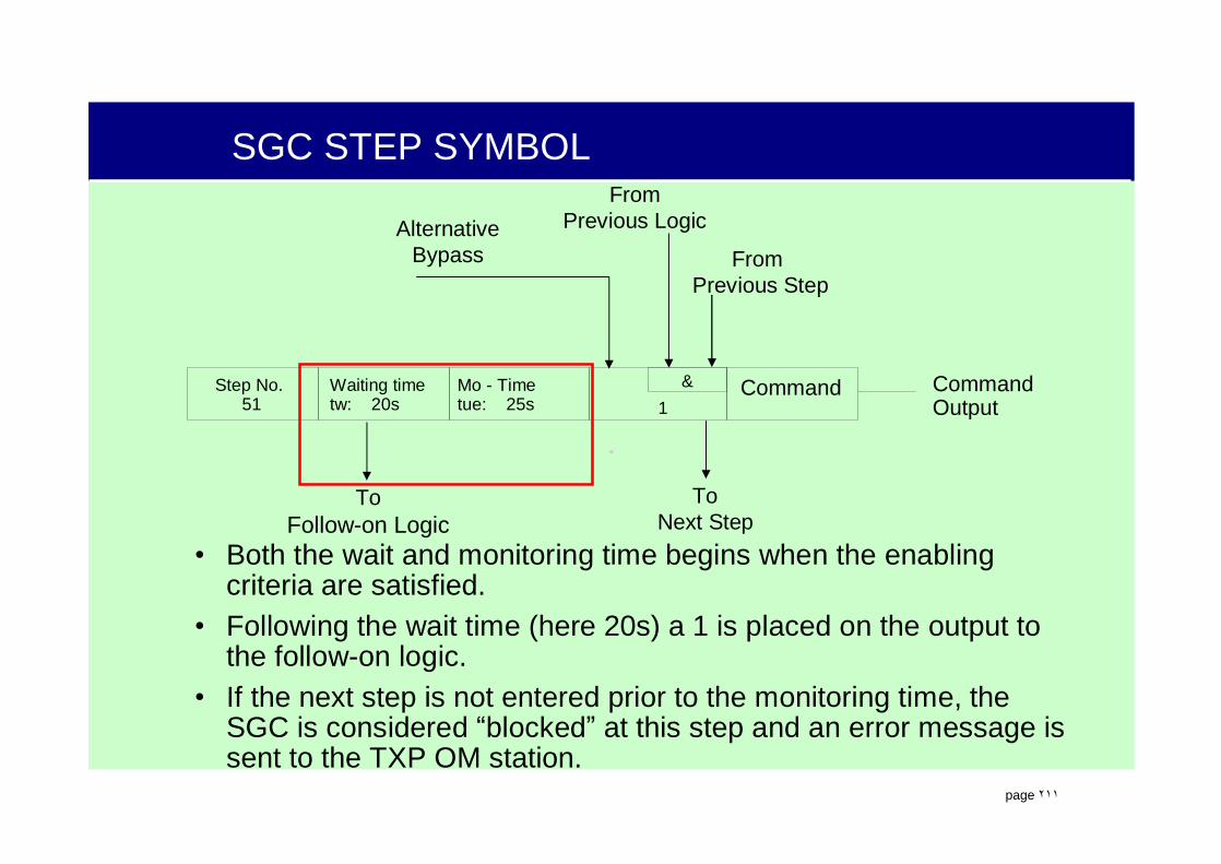
.
page ٢١١
SGC STEP SYMBOL
AlternativeBypass
FromPrevious Logic
From Previous Step
ToNext Step
CommandOutput
&Mo - TimeWaiting timeStep No.tue: 25stw: 20s51 1
Command
ToFollow-on Logic
• Both the wait and monitoring time begins when the enabling criteria are satisfied.
• Following the wait time (here 20s) a 1 is placed on the output to the follow-on logic.
• If the next step is not entered prior to the monitoring time, the SGC is considered “blocked” at this step and an error message is sent to the TXP OM station.

.
page ٢١٢
SGC STEP SYMBOL
Let’s walk through a complete step.
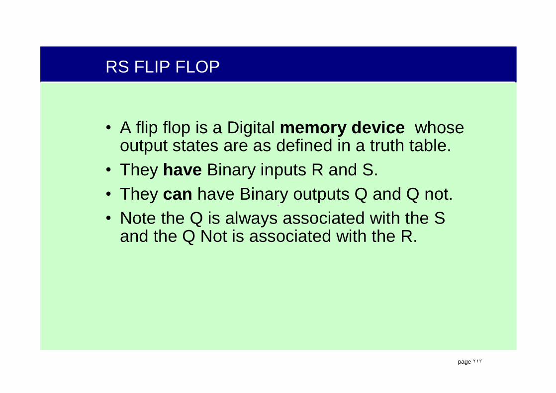
.
page ٢١٣
RS FLIP FLOP
• A flip flop is a Digital memory device whose output states are as defined in a truth table.
• They have Binary inputs R and S.• They can have Binary outputs Q and Q not. • Note the Q is always associated with the S
and the Q Not is associated with the R.

.
page ٢١٤
RS FLIP FLOP - RESET
• A flip flop is a binary memory device whose output states are as defined in a truth table. “S” in the truth table indicates that the output remains in the same or previous state.
• “Reset Sensitive” or “Reset Override” is the preferred state.
00
1
0
01
S010
11
SInputs Outputs
R Q QS10
R S
Q Q
Set
Reset
QQ NOT

.
page ٢١٥
RS FLIP FLOP - SET
• A flip flop is a binary memory device whose output states are as defined in a truth table. “S” in the truth table indicates that the output remains in the same or previous state.
• “Set Sensitive” or “Set Override” is the preferred state.
S R
Q Q
Set
Reset
QQ NOT
00
1
0
01
S011
11
SInputs Outputs
R Q QS1
00

.
page ٢١٦
RS FLIP FLOP
• This gate works the same as the previous Flip Flop.
• Note the Q is always associated with the S and the Q Not is associated with the R.
R S
Q Q
Set
Reset
QQ NOT
00
1
0
01
S011
11
SInputs Outputs
R Q QS100

.
page ٢١٧
SUB LOOP CONTROLLER
SLC
AON
OM
CBON
CBOFF
AOFF
00
1
0
01
S010
11
Inputs Outputs
Off
S10
Off
BLOM
• A Sub Loop Controller is used to keep defined process states. Functions like a RS flip flop.
• Automatic controls can “block” operator input by placing a “1” on BLOM input
• Priorities are:– Automatic “OFF”– Automatic “ON”– Manual “ON/OFF”
On On
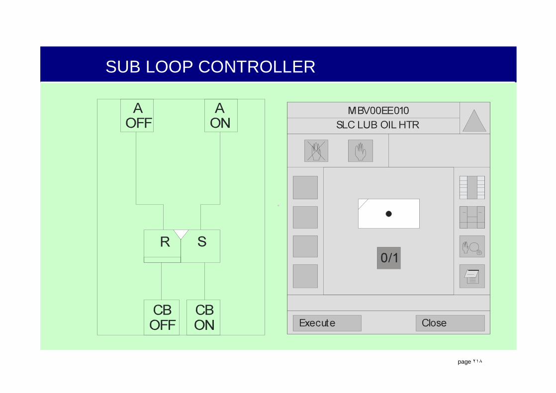
.
page ٢١٨
SUB LOOP CONTROLLER

.
page ٢١٩
DRIVE CONTROL MODULE
&
>1 >1
&
POFF
ENOFF
AOFF
AON
ENON
PON
CBOFF
CBON
R S
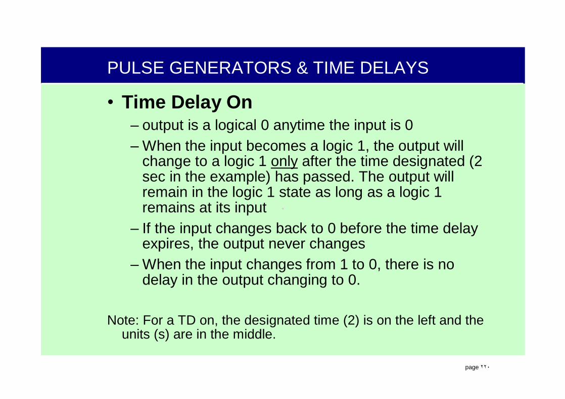
.
page ٢٢٠
PULSE GENERATORS & TIME DELAYS
• Time Delay On – output is a logical 0 anytime the input is 0– When the input becomes a logic 1, the output will
change to a logic 1 only after the time designated (2 sec in the example) has passed. The output will remain in the logic 1 state as long as a logic 1 remains at its input
– If the input changes back to 0 before the time delay expires, the output never changes
– When the input changes from 1 to 0, there is no delay in the output changing to 0.
Note: For a TD on, the designated time (2) is on the left and the units (s) are in the middle.
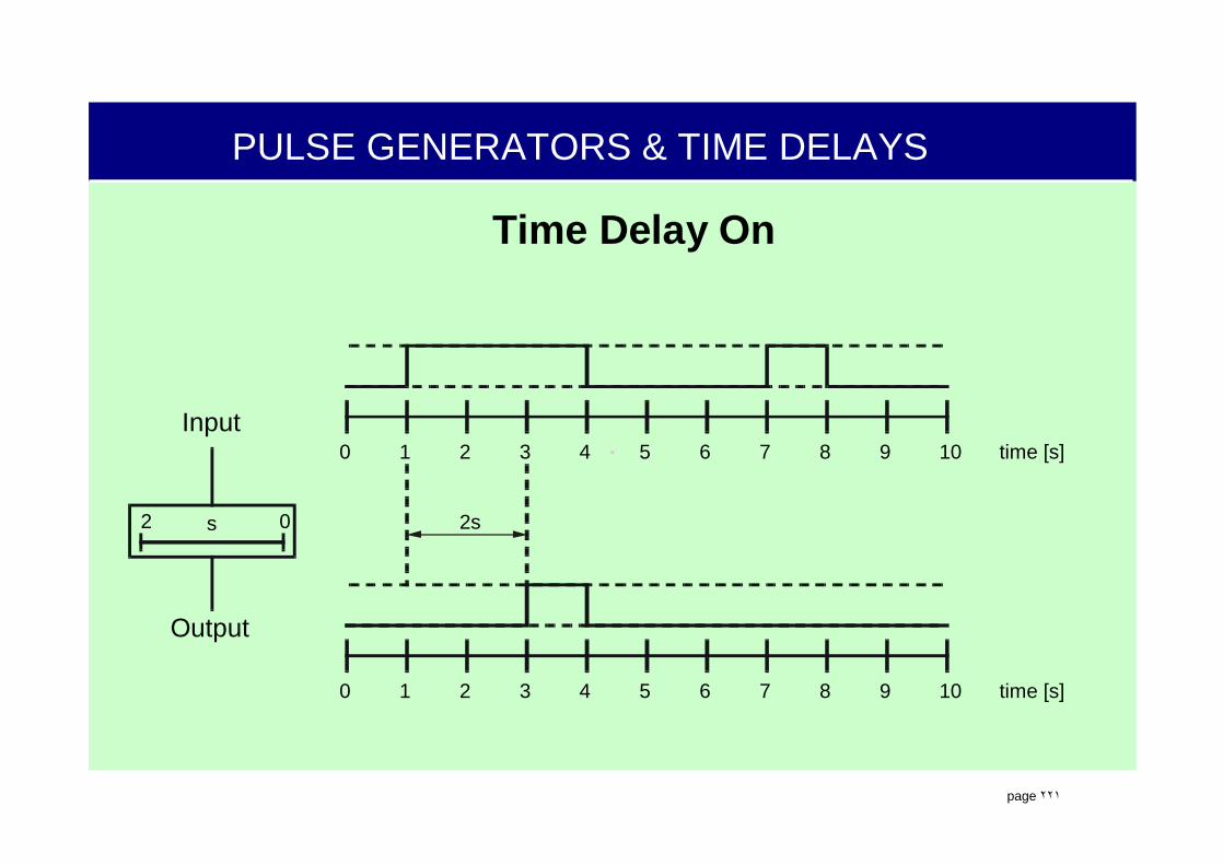
.
page ٢٢١
PULSE GENERATORS & TIME DELAYS
Time Delay On
0 1 2 3 4 5 6 7 8 9 10 time [s]
0 1 2 3 4 5 6 7 8 9 10 time [s]
2s2 0
Output
Input
s

.
page ٢٢٢
PULSE GENERATORS & TIME DELAYS
Time Delay Off (Sequence Timer Off Delay)• A time delay Off
– output is a logical 1 anytime the input is 1– When the input becomes a logical 0, the output becomes a
logical 0 after waiting the designated amount of time (2 sec in the example)
– When the input changes from 1 to 0, it must remain a 0 for a time interval equal to or greater than the time delay before the output will become 0. If the input changes back to 1 before the time delay expires, the output never changes
– When the input changes from 0 to 1, there is no delay in the output changing to 1.
Note: For a TD Off, the designated time (2) is on the right and the units (s) are in the middle.

.
page ٢٢٣
PULSE GENERATORS & TIME DELAYS
Time Delay Off
0 1 2 3 4 5 6 7 8 9 10 time [s]
0 1 2 3 4 5 6 7 8 9 10 time [s]
20
Output
Input
2s 2ss

.
page ٢٢٤
PULSE GENERATORS & TIME DELAYS
Max Pulse Generator (Pulse Generator)• A binary device that limits the time of the
output signal to a specific duration–With an input signal of extended time
duration, the output signal will be converted to an output (pulse) of a specified duration. The duration of the output signal (pulse) is defined in the middle portion of the rectangular symbol, in the symbol shown the output (pulse) duration is max. 2 seconds. If the input reverts to a 0 before the time period is complete, the output will immediately follow the input to the 0 state.

.
page ٢٢٥
PULSE GENERATORS & TIME DELAYS
Max Pulse Generator
0 1 2 3 4 5 6 7 8 9 10 time [s]
0 1 2 3 4 5 6 7 8 9 10 time [s]
2s
Output
Input
2s 1sMAX

.
page ٢٢٦
PULSE GENERATORS & TIME DELAYS
Pulse Generator (One Shot)• A pulse generator
–With input signals of varying time duration, the output signal will be converted to an output (pulse) of a specified duration. If the input signal is a logical 1 for greater than the specified duration, the output will be a logical 1 for the specified period of time (Input = 1 for 3 seconds, Output = 1 for 2 seconds). If the input signal is a logical 1 for less than the specified duration, the output will remain a logical 1 for the specified period of time (Input = 1 for 1 second, Output = 1 for 2 seconds).

.
page ٢٢٧
PULSE GENERATORS & TIME DELAYS
Pulse Generator (One Shot)
0 1 2 3 4 5 6 7 8 9 10 time [s]
0 1 2 3 4 5 6 7 8 9 10 time [s]
2s
Output
Input
2s 2s

.
page ٢٢٨
TIME TAGGING DEVICE
Data (Time Tagging Devices)
Binary time tag device, actually called DATA with time binary, records the time and change in a binary state. (FB79)
Analog time tag device, actually called DATA with time analog, records the analog signal and time based on signal change. (FB214)
TTDAP #
TTD AP

.
page ٢٢٩
ALARMS FOR BINARY TTD“E” - No Alarm“A” – Alarm (an analog value exceeded its alarm limit)“W” – Warning (an analog value exceeded its warning limit)“T” – Tolerance (an analog value exceeded its tolerance limit)“L” – Local fault has occurred (e.g. “tank level too high” on automatic tank overflow)“M” – Indicates that a Maintenance or service activity is necessary (e.g. “filter clogged; change to spare filter”)“C” – A status has Changed (e.g. changeover to a spare pump)
REV = Reversion of the edge of evaluation of input signal.0 rising edge generates TTD, 1 falling edge generates TTD

.
page ٢٣٠
YFR INPUTS AND OUTPUTS
Input signal function blocks are used with a SIM module to enable the AS 620B to read and monitor analog signals from the plant or other processors.
Output signal function blocks are used with a SIM module to enable the AS 620B to send analog signals to components in the plant or other processors.
.
page ٢٣١
Analog Signal Conditioning (FB74)
• The analog signal conditioning function block is used with a SIM module to enable the AS 620B to read and monitor analog signals from the plant.
I
KGAISIG
ATGS4
LV1 LV2
LV4 LV3
ULLL1 ULLL2
ULLL4 ULLL3
CHANNEL LRV
UNIT URV
GS3GS2GS1

.
page ٢٣٢
ANALOG SIGNAL CONDITIONING INPUT
• I =Analog Input LV = Limit Value• LRV = Physical Lower Limit URV = Physical Upper Limit• ULLL = Upper (1 or UL) or lower (0 or LL) limit value• UNIT = Defines measuring units (C or Bar, etc.)• GS = When limit reached becomes a 1 output• AI SIG = Analog signal output• KG = Outputs is 1 when analog signal input is OK
I
KGAISIG
ATGS4
LV1 LV2
LV4 LV3
ULLL1 ULLL2
ULLL4 ULLL3
CHANNEL LRV
UNIT URV
GS3GS2GS1

.
page ٢٣٣
ANALOG TRANSMITTER INPUT TYPES
• AT - This FB74 is used for analog input signals of 0-20 or 4 - 20 ma.
• RT - This FB77 is used for sensor conditioning of Resistance Thermometers.Input in S.
• TT - This FB76 is used for sensor conditioning of Thermocouples, J & K type. Input in mV.

.
page ٢٣٤
ANALOG SIGNAL CONDITIONING INPUT
I
KGAISIG
ATGS4
LV1 LV2
LV4 LV3
ULLL1 ULLL2
ULLL4 ULLL3
CHANNEL LRV
UNIT URV
GS3GS2GS1
11 13
LL LL 0
20 PSIG
-2
0 1 0 0
13.96 ma
112.45
-2

.
page ٢٣٥
ANALOG SIGNAL CONDITIONING

.
page ٢٣٦
ANALOG SIGNAL CONDITIONING

.
page ٢٣٧
ANALOG SIGNAL CONDITIONING INPUT
.
page ٢٣٨
ANALOG SIGNAL CONDITIONING INPUT

.
page ٢٣٩
BINARY SIGNAL CONDITIONING INPUT
• I = Binary Input• BI SIG = Binary signal output• KG = Outputs is 1 when binary signal input is OK
I
KGBISIG
BT CHANNEL

.
page ٢٤٠
LIMIT MONITOR
• The limit monitor takes an input analog variable (X) and compares it to a setpoint (GW). If the setpoint is reached, a limit signal (SWITCH) is placed on the output (Q).
• A hysteresis, or dead band, can also be assigned to the setpoint to prevent rapid toggling of the output.
• Can be used as a high or low monitor by setting switch value.
Q
XSWITCH
HYS
GW
Analog or Binary?
.
page ٢٤١
LIMIT MONITOR HIGH MODE
• Switch is set to 1• When X input is below
GW setpoint of 225, the Q output is a 0
Q
XSWITCH
HYS
GW
13
225
179
0

.
page ٢٤٢
LIMIT MONITOR HIGH MODE
• Switch is set to 1• When X input is below
GW setpoint of 225, the Q output is a 0
• When the X input exceeds the GW setpoint of 225, the Q output changes to a 1Q
XSWITCH
HYS
GW
13
225
225
1

.
page ٢٤٣
LIMIT MONITOR HIGH MODE
• Switch is set to 1• When X input is below
GW setpoint of 225, the Q output is a 0
• When the X input exceeds the GW setpoint of 225, the Q output changes to a 1
• As the X input decreases below GW setpoint, the Q output remains a 1,
Q
XSWITCH
HYS
GW
13
225
224
1
.
page ٢٤٤
LIMIT MONITOR HIGH MODE
• Switch is set to 1• When X input is below GW
setpoint of 225, the Q output is a 0
• When the X input exceeds the GW setpoint of 225, the Q output changes to a 1
• As the X input decreases below GW setpoint, the Q output remains a 1, until the value goes below the setpoint minus the hysteresis which would be 225 - 3 = 222 for our example
Q
XSWITCH
HYS
GW
13
225
222
1
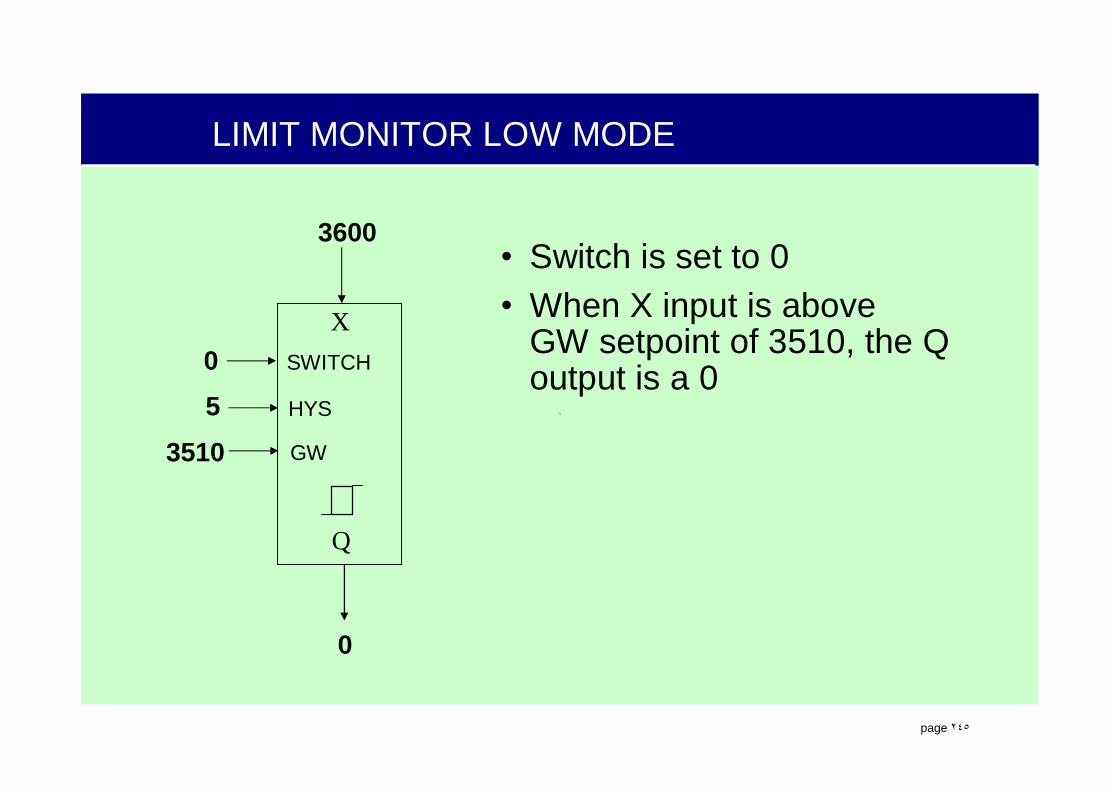
.
page ٢٤٥
LIMIT MONITOR LOW MODE
• Switch is set to 0• When X input is above
GW setpoint of 3510, the Q output is a 0
Q
XSWITCH
HYS
GW
05
3510
3600
0
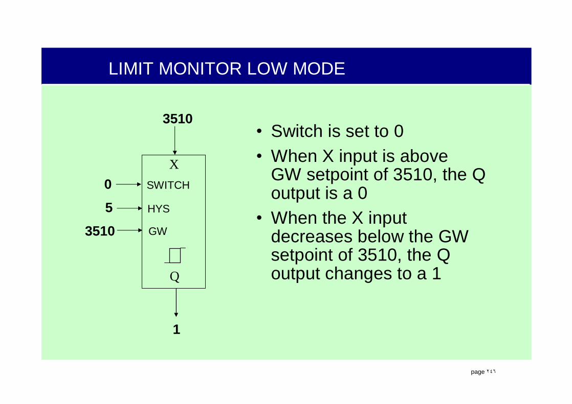
.
page ٢٤٦
LIMIT MONITOR LOW MODE
• Switch is set to 0• When X input is above
GW setpoint of 3510, the Q output is a 0
• When the X input decreases below the GW setpoint of 3510, the Q output changes to a 1Q
XSWITCH
HYS
GW
05
3510
3510
1

.
page ٢٤٧
LIMIT MONITOR LOW MODE
• Switch is set to 0• When X input is above
GW setpoint of 3510, the Q output is a 0
• When the X input decreases below the GW setpoint of 3510, the Q output changes to a 1
• As the X input increases above GW setpoint, the Q output remains a 1,
Q
XSWITCH
HYS
GW
05
3510
3513
1

.
page ٢٤٨
LIMIT MONITOR LOW MODE
• Switch is set to 0• When X input is above GW
setpoint of 3510, the Q output is a 0
• When the X input decreases below the GW setpoint of 3510, the Q output changes to a 1
• As the X input increases above GW setpoint, the Q output remains a 1, until the value goes above the setpointplus the hysteresis which would be 3510 + 5 = 3515 for our example
Q
XSWITCH
HYS
GW
05
3510
3515
0

.
page ٢٤٩
ANALOG SWITCH ASW (FB115)
• The analog switch function block optionally switches one of two analog inputs to the Y output.
• X1 and X2 are analog inputs, SWITCH is a binary input and Y is an analog output.
• Figure is drawn in the “de-energized” position or as if the switch input was a 0.
F
#
Y
SWITCH
X2X1

.
page ٢٥٠
ANALOG SWITCH ASW
• With the switch input set to 0, the X1 input is passed to the Y output.
F
#
210 223
210
0
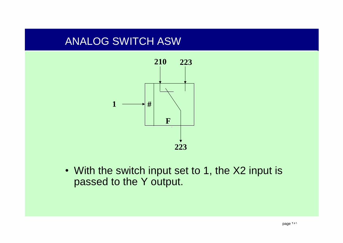
.
page ٢٥١
ANALOG SWITCH ASW
• With the switch input set to 1, the X2 input is passed to the Y output.
F
#
210 223
223
1

.
page ٢٥٢
MATHEMATICAL FUNCTIONS
Summation and Subtraction
++
-+
+-
Analog or Binary?
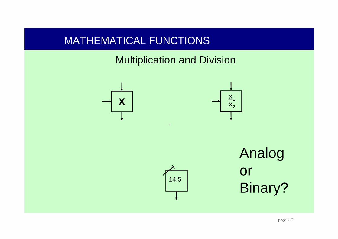
.
page ٢٥٣
MATHEMATICAL FUNCTIONS
Multiplication and Division
X1X2
14.5
X
Analog or Binary?
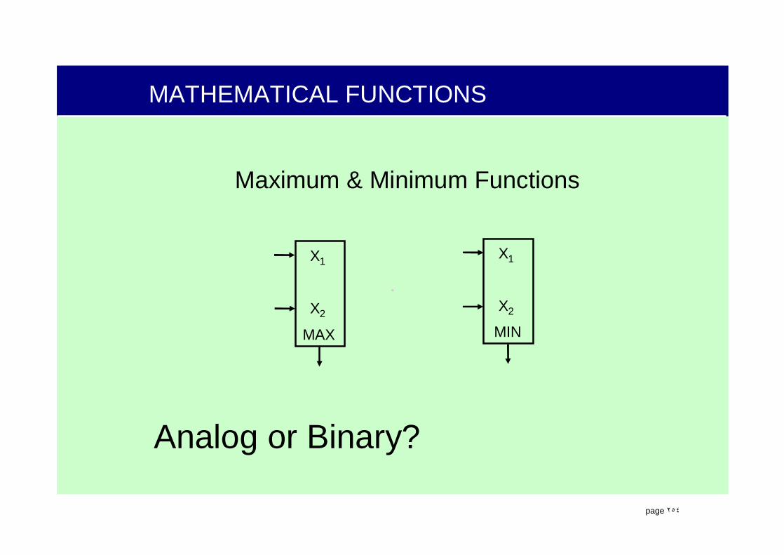
.
page ٢٥٤
MATHEMATICAL FUNCTIONS
Maximum & Minimum Functions
X1
X2
MAX
X1
X2
MIN
Analog or Binary?

.
page ٢٥٥
MATHEMATICAL FUNCTIONS
Mean Value (Average Function) (FB 189)
X1
EN1
X2
EN2
X3
EN3
Σ/n
AVER
Analog or Binary?
Determines the mean value of up to 16 analog inputs. EN must be a binary one to use that signal.
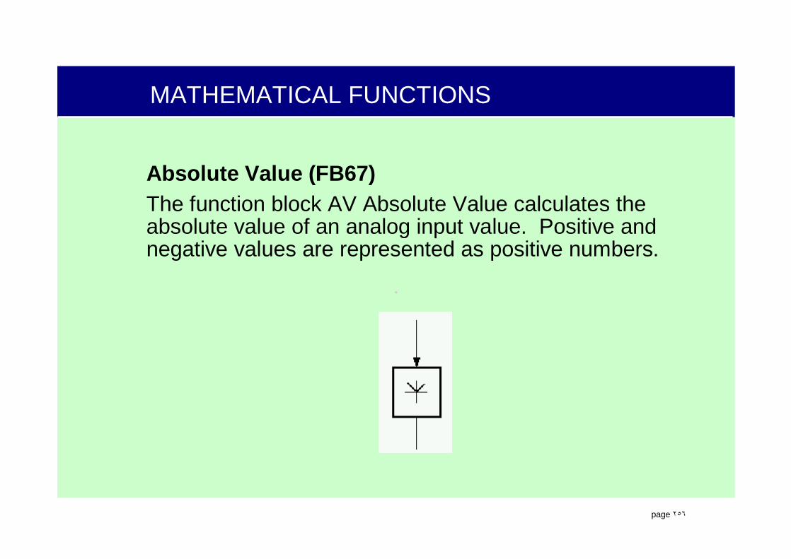
.
page ٢٥٦
MATHEMATICAL FUNCTIONS
Absolute Value (FB67)The function block AV Absolute Value calculates the absolute value of an analog input value. Positive and negative values are represented as positive numbers.

.
page ٢٥٧
PRESELECTION FB137
• The preselection function block allows the AS 620 B to store an operators preselections
• Precedence:–Selection 1–Selection 2–Selection 3
OMSELECTENSELM
COMSEL1
COMSEL3
COMSEL2
CBSEL1
CBSEL3
CBSEL2
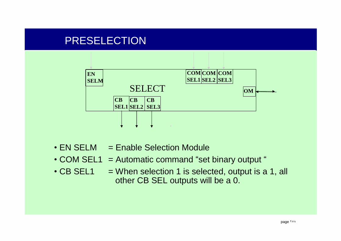
.
page ٢٥٨
PRESELECTION
• EN SELM = Enable Selection Module• COM SEL1 = Automatic command “set binary output “• CB SEL1 = When selection 1 is selected, output is a 1, all
other CB SEL outputs will be a 0.
OMSELECTENSELM
COMSEL1
COMSEL3
COMSEL2
CBSEL1
CBSEL3
CBSEL2
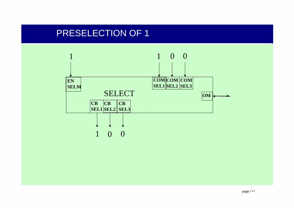
.
page ٢٥٩
PRESELECTION OF 1
OMSELECTENSELM
COMSEL1
COMSEL3
COMSEL2
CBSEL1
CBSEL3
CBSEL2
1 1
1
0
0 0
0

.
page ٢٦٠
PRESELECTION OF 2
OMSELECTENSELM
COMSEL1
COMSEL3
COMSEL2
CBSEL1
CBSEL3
CBSEL2
1 0
0
1
1 0
0

.
page ٢٦١
PRESELECTION EXAMPLE
Pulse output or continuous

.
page ٢٦٢
ANALOG SELECTION 2-OUT-OF-3
Deviation allowed
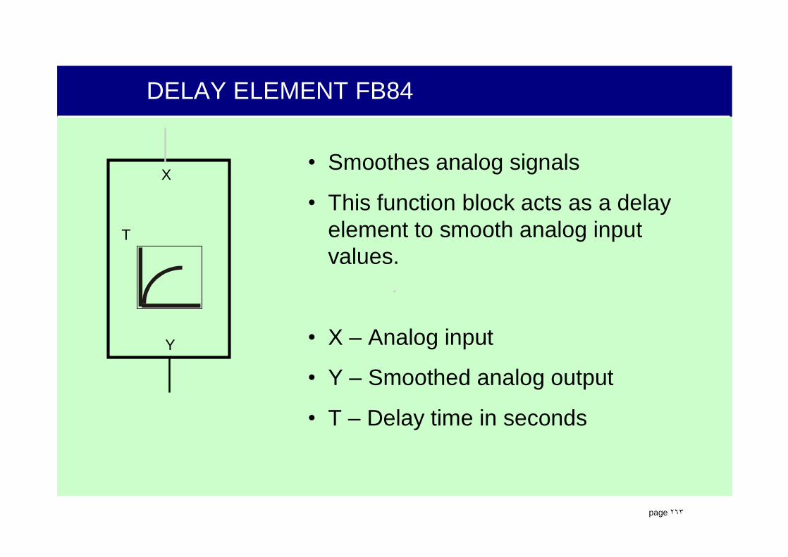
.
page ٢٦٣
DELAY ELEMENT FB84
T
Y
X• Smoothes analog signals
• This function block acts as a delay element to smooth analog input values.
• X – Analog input
• Y – Smoothed analog output
• T – Delay time in seconds

.
page ٢٦٤
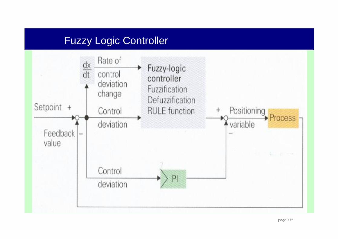
.
page ٢٦٥
Fuzzy Logic Controller

.
page ٢٦٦
Acknowledgement
Best regards to:Ditmar ReppmanMajid Dini
Contact:0935 2223936e.mail:[email protected]
Any question?