“in-vitro” langendorff heart perfusion system - wpiinc.com · instruction manual serial...
TRANSCRIPT

INSTRUCTION MANUAL
Serial No._____________________
120712
World Precision Instruments
ww
w.w
pii
nc.c
om
SI-LANG1“In-vitro” Langendorff Heart Perfusion System

SI-LANG1
II WORLD PRECISION IN STRU MENTS
SI-LANG1
WORLD PRECISION IN STRU MENTS iii
Copyright © 2012 by World Precision Instruments, Inc. All rights reserved. No part of this publication may be
reproduced or translated into any language, in any form, without prior written permission of World Precision
Instruments, Inc.
CONTENTSABOUT THIS MANUAL ............................................................................................................................... 1INTRODUCTION ........................................................................................................................................... 2
Cautions and Warnings ........................................................................................................................ 3Parts List ..................................................................................................................................................... 3Unpacking ................................................................................................................................................. 3
INSTRUMENT DESCRIPTION .................................................................................................................... 4Hardware Description............................................................................................................................ 4Setup ............................................................................................................................................................ 5Plumbing the System ...........................................................................................................................12
Temperature Regulation Circuit ..................................................................................................14Carbogen Circuit ..............................................................................................................................16Perfusion Circuit ...............................................................................................................................17
Filling The System .................................................................................................................................18Filling the Temperature Regulation Circuit .............................................................................18Filling the Perfusion Circuit ..........................................................................................................19
Installing the Sensors ...........................................................................................................................20Pressure Sensors ..............................................................................................................................20Temperature Sensor .......................................................................................................................21Stimulation Electrodes (optional) ...............................................................................................22
MAP (ECG) Electrodes (optional) .......................................................................................................24OPERATING INSTRUCTIONS ...................................................................................................................26
Mounting the Preparation..................................................................................................................27Operating the Valve Taps ...................................................................................................................28
Constant Pressure Mode .............................................................................................................28Constant Flow Mode .....................................................................................................................29
MAINTENANCE ............................................................................................................................................30QUICK REFERENCE CHECKLIST ............................................................................................................30APPENDIX A: TUBING INFORMATION ...............................................................................................31APPENDIX B: EPP-01 PERISTALTIC PUMP .........................................................................................33
General Description..............................................................................................................................33Specifi cations ..........................................................................................................................................33Installation Instructions.......................................................................................................................33Tubing Inspection..................................................................................................................................34
Tubing Replacement ......................................................................................................................34INDEX .............................................................................................................................................................35WARRANTY ..................................................................................................................................................36
Claims and Returns ..............................................................................................................................36

SI-LANG1
IV WORLD PRECISION IN STRU MENTS

SI-LANG1
WORLD PRECISION IN STRU MENTS 1
ABOUT THIS MANUAL
The following symbols are used in this guide:
This symbol indicates a CAUTION. Cautions warn against actions that can cause damage to equipment. Please read these carefully.
This symbol indicates a WARNING. Warnings alert you to actions that can cause personal injury or pose a physical threat. Please read these carefully.
NOTES and TIPS contain helpful information.
Fig. 1–The Langendorff shown has two columns. In this document we will discuss the one column Langendorff system.

SI-LANG1
2 WORLD PRECISION IN STRU MENTS
INTRODUCTION
Studies on coronary circulation can easily be accomplished using an apparatus known as a Langendorff system. These devices perfuse isolated heart preparations from small mammalian species through a cannula inserted into the aorta of the heart. The perfusion buffer fl ows into the heart through the aorta and puts pressure on the aortic valves to close. The perfusion fl uid has nowhere to go but through the coronary arteries that come off the side of the aorta. Since the fl ow of blood into the heart during this type of perfusion is the reverse of normal blood fl ow, Langendorff methods are known as retrograde perfusions. Also, the hearts subjected to Langendorff perfusion are described as being non-working since the heart does not work as it does in vivo. Langendorff systems are useful for measuring the effectiveness of drugs on the vasodilation and vasoconstriction of coronary arteries, and the resultant effects of increased or decreased cardiac perfusion.
Fig. 2–This plumbing diagram shows how oxygen, water and perfusion buffer run through the Langendorff system.
SI-LANG1
WORLD PRECISION IN STRU MENTS 3
Cautions and WarningsCAUTION: Unpacking and installing the system requires more then one person. Beware of the heavy weight of the heavy-duty parts (for example, stands, larger glass or Plexiglas units, etc.).
UnpackingUpon receipt of this instrument, make a thorough inspection of the contents and check for possible damage. Missing cartons or obvious damage to cartons should be noted on the delivery receipt before signing. Concealed damage should be reported at once to the carrier and an inspection requested. Please read the section entitled “Claims and Returns” on page 36 of this manual. Please contact WPI Customer Service if any parts are missing at 941.371.1003 or [email protected].
Returns: Do not return any goods to WPI without obtaining prior approval (RMA # required) and instructions from WPI’s Returns Department. Goods returned (unauthorized) by collect freight may be refused. If a return shipment is necessary, use the original container, if possible. If the original container is not available, use a suitable substitute that is rigid and of adequate size. Wrap the instrument in paper or plastic surrounded with at least 100mm (four inches) of shock absorbing material. For further details, please read the section entitled “Claims and Returns” on page 36 of this manual.

SI-LANG1
4 WORLD PRECISION IN STRU MENTS
INSTRUMENT DESCRIPTION
Hardware Description
Base Plate
Supporting Stand
Perfusion Column
Pump to fillPerfusion Column
2-Way TeflonStopcocks
Heart Suspension Unit
Heart Chamber
Pressure Sensor
Water Drain
Spindle SyringeCarbogen PressureRegulator
Stainless Steel Sink
Table
Shelf
3-Way TeflonStopcocks
Fig. 3–The components of this Langendorff are labeled.

SI-LANG1
WORLD PRECISION IN STRU MENTS 5
Setup1. The table that supports this Langendorff system is delivered in pieces with the legs,
cross beams, shelf and table top packed separately. Carefully remove the wrapping from the components. Keep the foam pad in the stainless steel tray on top of the table to prevent damaging the edges of the table. The table top is designed to collect any fl uids that might drip from the system. Lay the table top face down on a work table or the fl oor (Fig. 4).
Fig. 4–Turn the table upside down.
2. Install the table legs.
Fig. 5– (Left) Position the H-shaped legs of the table.Fig. 6– (Right) Schematic shows how to lock the table legs into place.
A. Align the top of one of the “H” shaped legs of the table against the cross beams mounted on the bottom of the table (Fig. 5).
B. Slide the spring-loaded nuts (A) into the tracks of the legs and align them with the threaded tubes (B) in the table frame (Fig. 6).
C. Push the hex screws (C) into the threaded tubes with the Allen wrench (D) (Fig. 7). D Thread the screws into the nuts and rotate them until they are snug (Fig. 8).E. Attach the other leg to the table top in the same manner as the fi rst leg.

SI-LANG1
6 WORLD PRECISION IN STRU MENTS
Fig. 7– (Left) Push the hex screws into place.Fig. 8– (Right) Tighten the screws.
3. Attach the lower cross beams between the two sets of legs in the same manner as the legs are attached (Fig. 9).
Fig. 9– (Left) Attach the cross bars.Fig. 10– (Right) Place the shelf under the table.
4. Setup the table.A. Turn the table over and place it where the system will be used. Check the
stability of the table. Adjust the height of the feet on the table to level it.B. Place the shelf on the lower crossbars of the table (Fig. 10).C. Remove the foam pad from the tray top of the completed table.
5. Attach the frame rack of the system to the table. A. With the assistance of another person, align the holes on the bottom of the
frame rack with the mounting holes on the table top (Fig. 11).

SI-LANG1
WORLD PRECISION IN STRU MENTS 7
B. As one person holds the frame rack in position, the other person should use four Allen screws and fl at washers to fi x the frame rack to the top of the table. Tighten the screws fi rmly.
Fig. 11– Attach the frame rack.
NOTE: Assemble the perfusion column and the overfl ow tube before mounting them on the frame rack.
6. Carefully remove the perfusion column and the overfl ow tube from the packing box. Lay them down on a work table and make sure that they are secure. • The overfl ow tube has
already been fi tted with parts (1-5, 7 in Fig. 12) that are needed for mounting it in the perfusion column, and a silicone grommet near its top to protect the tube if it touches the inside of the column.
• The perfusion column has already been fi tted with the blocks that mount it to the frame rack, and a hollow nut (6 in Fig. 12) on the bottom of the column that is used to secure the overfl ow tube in the column.
Fig. 12–The exploded view shows how the perfusion column fi ts together.
7. Assemble the perfusion column.A. Remove the hollow nut from the column. B. Carefully feed the upper end of the overfl ow tube, with its grommet, through the
opening in the bottom of the perfusion column until the shoulder of the Tefl on
1 Perfusion Column2 Inner O-ring3 Outer O-ring4 Teflon Holder5 Teflon Gasket6 Hollow Screw7 Hollander8 Overflow Tube
1
2
2
3
3
4
4
5
7
7
6
8
888888 7888888 7777
64

SI-LANG1
8 WORLD PRECISION IN STRU MENTS
tube support (4 in Fig. 12) touches the bottom of the column. C. Reinstall the hollow nut over the end of the overfl ow tube and onto the bottom
of the perfusion column.D. Finger-tighten the hollow nut to secure the overfl ow tube in the column.
CAUTION: Be sure the inner (2) and outer (3) O-rings and the Tefl on gasket (5) are installed on the tube support (4) before assembling the perfusion column.
NOTE: The height of the overfl ow tube sets the pressure used to perfuse the heart in Langendorff mode. To adjust the height of the overfl ow tube, loosen the knurled nut (7 in Fig. 12) and carefully slide the overfl ow tube to the correct position. If the tube does not slide, loosen the knurled nut a little more. Once the tube is in position, fi nger-tighten the knurled nut to secure the overfl ow tube.
8. Mount the assembled perfusion column to the left side of the frame rack (Fig. 13). The mounting blocks for the perfusion column are already positioned on the column and should align with the mounting holes on the frame rack. With the assistance of another person, attach the perfusion column and its mounting blocks to the frame rack using the four (4) cap screws provided.
Fig. 13– Mount the perfusion column to the left side of the frame.

SI-LANG1
WORLD PRECISION IN STRU MENTS 9
9. Mount the valve tap assembly (Fig. 15) to the central crossbar of the frame rack.
Fig. 14–The labeled diagram shows components of the valve tap assembly.
Fig. 15–(Left) Mount the valve tap assemblyFig. 16–(Right) Secure the rods of the tap valve support to the crossbar.A. Loosen the two knobs on the holes in the center of the crossbar (Fig. 16). B. Push the rods of the tap valve support into the holes on the crossbar. C. Tighten the knobs to secure the tap valve assembly to the frame rack.
SI-LANG1
10 WORLD PRECISION IN STRU MENTS
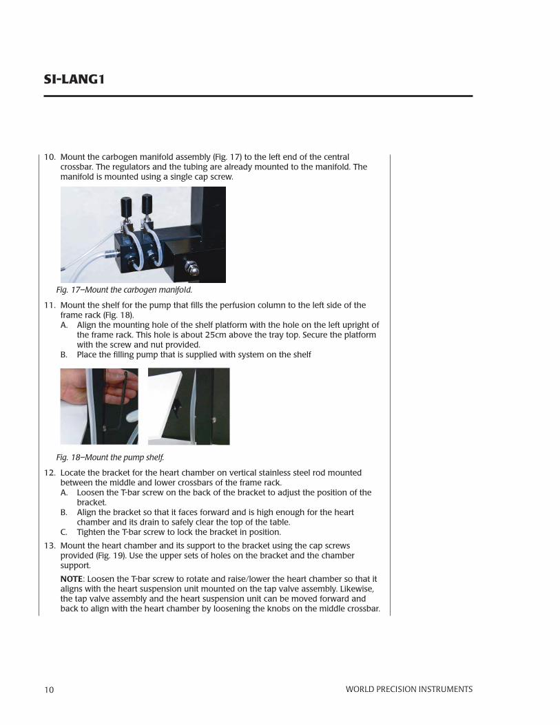
10. Mount the carbogen manifold assembly (Fig. 17) to the left end of the central crossbar. The regulators and the tubing are already mounted to the manifold. The manifold is mounted using a single cap screw.
Fig. 17–Mount the carbogen manifold.
11. Mount the shelf for the pump that fi lls the perfusion column to the left side of the frame rack (Fig. 18). A. Align the mounting hole of the shelf platform with the hole on the left upright of
the frame rack. This hole is about 25cm above the tray top. Secure the platform with the screw and nut provided.
B. Place the fi lling pump that is supplied with system on the shelf
Fig. 18–Mount the pump shelf.
12. Locate the bracket for the heart chamber on vertical stainless steel rod mounted between the middle and lower crossbars of the frame rack.A. Loosen the T-bar screw on the back of the bracket to adjust the position of the
bracket.B. Align the bracket so that it faces forward and is high enough for the heart
chamber and its drain to safely clear the top of the table.C. Tighten the T-bar screw to lock the bracket in position.
13. Mount the heart chamber and its support to the bracket using the cap screws provided (Fig. 19). Use the upper sets of holes on the bracket and the chamber support.
NOTE: Loosen the T-bar screw to rotate and raise/lower the heart chamber so that it aligns with the heart suspension unit mounted on the tap valve assembly. Likewise, the tap valve assembly and the heart suspension unit can be moved forward and back to align with the heart chamber by loosening the knobs on the middle crossbar.

SI-LANG1
WORLD PRECISION IN STRU MENTS 11
Fig. 19– Mount the heart chamber.
14. Mount the heart suspension unit to the front of the valve tap assembly (Fig. 21). Make sure there is enough clearance between the valve tap assembly and the heart chamber to mount the suspension unit.
Screw
A B C D
Fig. 20– Follow the steps to mount the heart suspension unit.Fig. 21– (Left) The heart suspension unit is mounted. A. Loosen the screw on the side of the mounting bracket in the front of the valve
tap (Fig. 20, A).B. Carefully push the stem of the heart suspension unit into the front mounting hole
(Fig. 20, B and C).C. Gently tighten the mounting screw to hold the suspension unit snuggly in place.
CAUTION: Do not overtighten the mounting screw! Too much pressure on the
stem of the suspension unit will cause it to crack.
D. Attach a three-way stopcock, with an attached piece of silicone tubing, to the top of the stem for the purpose of fl ushing and draining the heart suspension unit. (Fig. 20, D)

SI-LANG1
12 WORLD PRECISION IN STRU MENTS
1 Bubble trap (usually with a 3-way plastic tap on the top)
2 Infl ow of the buffer
3 Sensor connection to measure buffer temperature
4 Heating unit to compensate for temperature loss
5 Sensor connection to monitor column pressure
6 Port for drug administration (Silicone membrane for bolus administration or infusion)
7 Cannula for suspending the heart, according to its size
8 Water jacket inlets and outlets
Fig. 22–The heart suspension unit is shown from two different angles.
Plumbing the SystemThe plumbing of Langendorff and working heart systems are organized into three distinct circuits (Fig. 23):
• The regulation of the temperature of the organ and the perfusion buffer• The movement of perfusion fl uid in the system• The oxygenation of the perfusion fl uid and the organ.
The circuits are coded in different colors and the arrows indicate the direction of water, perfusion buffer and oxygen movement.
Diagrams of the individual circuits (Fig. 24, Fig. 26, Fig. 28) that show only the components that are related to each circuit are useful for completing the tubing connections. Many of the components in a circuit may already have tubing attached to them. In some cases, completing sections of the circuit are as simple as connecting the open end of the tubing on one component to another component. A table that lists the lengths and diameters of the tubing pieces in all three circuits, and a numbered diagram that pinpoints the location of each piece of tubing in each circuit, can be found at the end of this manual.

SI-LANG1
WORLD PRECISION IN STRU MENTS 13
Fig. 23– Plumbing diagram showing all three circuits.

SI-LANG1
14 WORLD PRECISION IN STRU MENTS
Temperature Regulation Circuit Complete the connections between the water jackets of the required components and the recirculating water bath using the following directions (Fig. 24).
Fig. 24– Water Jacket plumbing diagram.
1. Connect the outlet of the recirculating water bath to the water jacket inlet at the bottom of the heart chamber.

SI-LANG1
WORLD PRECISION IN STRU MENTS 15
2. Connect the water jacket outlet at the top of the heart chamber to the large inlet on the lower fork of the water bypass assembly.
3. Connect the small tube on the lower fork of the water bypass assembly to the lower water jacket inlet on the back of the heart suspension unit.
4. Connect the upper water jacket outlet of the heart suspending unit to the water jacket inlet on the front of the secondary heat exchanger using a short silicone tube.
5. Connect the small tube on the upper fork of the water bypass assembly to the water jacket outlet on the back of the secondary heat exchanger.
Fig. 25– Heart suspension unit and secondary heat exchanger showing the tubing connections between these components.
6. Connect the large outlet of the upper fork of the water bypass assembly to the water jacket inlet on the bottom of the primary heat exchanger using a piece of silicone tubing.
7. Connect the water jacket outlet on the top of the primary heat exchanger to the water jacket inlet on the lower side of the perfusion column using a piece of silicone tubing.
8. Connect the water jacket outlet on the upper side of the perfusion column to the inlet of the recirculating water bath using a long piece of silicone tubing
CAUTION: When the circuit is complete, make sure it is fi lled with deionized water
only.

SI-LANG1
16 WORLD PRECISION IN STRU MENTS
Carbogen Circuit Complete the connections between the carbogen supply and the aeration frits in the reservoirs using the following directions (Fig. 26).
Fig. 26– Carbogen circuit plumbing diagram.
1. Connect the pressure regulator and valves on the carbogen cylinder to the manifold and regulators on the left side of the frame rack using the thin silicone tubing already attached to the inlet of the carbogen manifold.
2. A piece of silicone tubing has been attached to the outlet of each carbogen regulator of the aeration manifold that is located on the left side of the frame rack. Connect the regulator with the shorter piece of silicone tubing to the Luer fi tting and 3-way stopcock on the aeration frit of the perfusion column (Fig. 27).
3. The second regulator with the longer piece of tubing can be used to aerate the optional second perfusion column through its Luer fi tting and 3-waystopcock.
Fig. 27– (Right) Carbogen connection.

SI-LANG1
WORLD PRECISION IN STRU MENTS 17
Perfusion Circuit Complete the connections between the components that perfuse the heart using the following directions (Fig. 28).
Fig. 28– Perfusion circuit diagram.
1. Place a carboy, which will eventually hold fresh perfusion buffer, on the left side of the shelf under the tray top.
2. Place the open end of the silicone tubing, which is attached to the bottom of the overfl ow tube in the perfusion column, through the hole on the left side of the tray top and into the carboy that will hold perfusion buffer. Make sure the end of this tubing does not go below the surface of the buffer when the carboy is fi lled.

SI-LANG1
18 WORLD PRECISION IN STRU MENTS
3. Connect a piece of silicone tubing to the inlet tube of the pump used to fi ll the perfusion column. Put the open end of this tubing into the buffer carboy. The tubing should be long enough to reach the bottom of the carboy.
4. Attach another piece of silicone tubing between the outlet of the fi ll pump and the fi lter and tubing that is already mounted on the upper fi ll port of the perfusion column.
5. Use a piece of silicone tubing to connect the buffer outlet at the bottom of the perfusion column to the upper inlet port (stub 1) on the back of the three-way valve..
6. Use another piece of silicone tubing to connect the left outlet (stub 2) of the three-way valve to the inlet of the precision peristaltic pump.
7. Connect the outlet of the peristaltic pump to the bottom inlet (stub 3) of the three-way valve with another piece of silicone tubing.
8. Connect the right outlet (stub 4) of the three-way valve to the upper inlet of the primary heat exchanger with a piece of silicone tubing.
9. Use a piece of silicone tubing to connect the lower outlet of the primary heat exchanger to the left inlet (stub 2) of the two-way valve.
10. Use another piece of silicone tubing to connect the bottom outlet (stub 3) of two-way valve to the back inlet of the secondary heat exchanger (Fig. 25).
11. Connect the front outlet of the secondary heat exchanger to the upper buffer inlet on the back of the heart suspension unit with a short piece of silicone tubing (Fig. 25).
12. Connect a piece of silicone tubing to the drain on the bottom of the heart chamber. Place the open end of this tubing through the hole on the right side of the tray top and into a second carboy that is designated as the waste container for the fl uids used in the system. Make sure the end of this tubing does not go below the surface of the buffer when the carboy is fi lled.
Filling The System
Filling the Temperature Regulation Circuit1. Follow the directions for operating the circulating heated water bath that are
provided by its manufacturer.
2. Fill the reservoir of the circulating water bath with deionized water.
3. Turn on the water bath and set the temperature needed for the experiment.
4. Activate the pump of the bath to move water from the reservoir into the water jackets of the columns and chambers. As water moves into the system, replenish the water in the reservoir until the water jackets are full.
CAUTION: Most recirculating water baths have a safety sensor that will turn off the heater and pump automatically if the water level drops below a critical level. If the water bath turns off because the water level is low, add water to the reservoir
and restart the water bath.

SI-LANG1
WORLD PRECISION IN STRU MENTS 19
5. Check the water level in the reservoir every day. Add water to the reservoir, if needed.
Filling the Perfusion Circuit1. Make at least 5L of perfusion buffer (Krebs-Henseleit or similar). This is the volume
required to fi ll the perfusion circuit of the system. Fill the clean carboy on the shelf under the left side of the tray top with the fresh buffer.
2. Place the silicone tubing on the inlet of the fi ll pump under the surface of the buffer in the carboy. Place the tubing on the overfl ow of the perfusion column in the carboy, but not under the surface of the buffer.
3. Set the desired hydrostatic pressure used to perfuse the heart by moving the overfl ow tube of the perfusion column up or down. Determine the height that the open end of the overfl ow tube needs to be above the aorta of the heart to set the desired perfusion pressure.
Calculate the height needed by multiplying the desired perfusion pressure (in mmHg) by the 13.6 conversion factor. For example, to achieve a perfusion pressure of 60mmHg, the end of the overfl ow tube needs to be 816mm above the level of the aorta of the isolated heart.
NOTE: To adjust the height of the overfl ow tube, loosen the knurled nut (7 in Fig. 12) and carefully slide the overfl ow tube to the correct position. If the tube does not slide, loosen the knurled nut a little more. Once the tube is in position, fi nger-tighten the knurled nut to secure the overfl ow tube.
4. Start the fl ow of carbogen to the aeration inlet of the perfusion column. Open the valves on the cylinder of carbogen. Open the regulators on the aeration manifold and the 3-way stopcocks on the aeration inlet of the column. Begin the fl ow of carbogen through the aeration line before the perfusion fl uid is added to the system
5. Turn on the fi ll pump to move buffer into the perfusion column. The column will continue to fi ll until the fl uid level reaches the top of the overfl ow tube. Any excess fl uid in the perfusion column will fl ow down the overfl ow tube and back into the fresh buffer carboy. Keep the pump running while the rest of the system is being fi lled.
6. Rotate the tap on the three-way valve to the constant fl ow position (Position A on Fig. 28).
7. Turn on the precision peristaltic pump to move perfusion buffer through the pump and the three-way valve to the primary heat exchanger.
8. Open the two-way valve by rotating the tap to the side to fi ll the remaining components in the perfusion system with buffer. When the perfusion system is fi lled properly, buffer should fl ow out of the end of the aortic cannula without bubbles.
9. When the buffer is bubble-free close the two-way and three-way valves and turn off the precision peristaltic pump. Keep the column fi lling pump running.

SI-LANG1
20 WORLD PRECISION IN STRU MENTS
10. Turn on the recirculating water bath and begin warming the system and perfusion buffer. Start warming the system 30 to 60 minutes before starting the isolation of the heart. Also, it takes at least 30 minutes for the PO2 and PCO2 values of the buffer to reach equilibrium.
Installing the Sensors
Pressure Sensors1. The bodies of the pressure transducers are installed in holders on the left and right
sides of the two-way valve bracket (Fig. 29). Push in the spring loaded plate in the center of the holder and slide the sides of the sensor body under the retaining rails of the holder. Make sure the sensor is oriented so that the cable of sensor is pointed to the rear of the system.
Fig. 29– Install the pressure transducers in the holders on the left and right sides of the valve tap bracket.
2. Install the sensor that measures the perfusion pressure in Langendorff mode on the left side of the valve tap assembly.A. Attach a 3-way stopcock with an empty 2mL syringe to the rear port of the
pressure sensor to pull buffer into the sensor and its PVC line, and to close off the syringe when measurements are made.
B. Attach tubing, which matches the pressure port on the heart suspension unit, to the front of the pressure sensor
C. Attach the open end of the tubing to the lower port on the back of the heart suspension unit.
3. If the left ventricular pressure ( LVP) is going to be measured, install another sensor on the right side of the valve tap assembly. A. Attach a PVC cannula and needle to the front of the LVP sensor. The cannula
should match the balloon being used as the catheter in the left ventricle of the heart being studied.

SI-LANG1
WORLD PRECISION IN STRU MENTS 21
B. Attach a 3-way stopcock to the rear port of the LVP sensor.C. Attach the tubing from the spindle syringe, which is used to set the diastolic
pressure of the heart, to the stopcock on the rear of the LVP sensor.
Temperature Sensor1. Connect the plastic tube around the end of the temperature sensor to the stainless
steel tube on the side of the heart suspension unit. The end of the temperature sensor should not touch the metal tube on the inlet.
2. Mount the cable clamp for the lead wire of the temperature sensor on the back of the heart chamber support bracket while the heart chamber is lowered.
3. With the heart chamber still lowered, place the cable of the temperature sensor in the slot of the clamp (Fig. 30). Gently tighten the retaining screw to hold the cable in place. Make sure the cable is aligned so that it does not touch the heart, or it is not damaged when the heart chamber is raised.
Fig. 30– (Left) Clamp for cable of the temperature sensor.Fig. 31–(Right) The cable from the temperature sensor slides through the slot on the clamp.

SI-LANG1
22 WORLD PRECISION IN STRU MENTS
Stimulation Electrodes (optional)1. Screw the mounting post to the bottom of the valve tap assembly (Fig. 32).
Fig. 32– (Left) Insert the mounting post.Fig. 33– (Right) Attach the offset arm.
2. Attach the offset arm that suspends the stimulation electrode from the mounting post (Fig. 33).
3. Attach the ball joint bracket of either the monopolar or bipolar stimulation electrode to the end of the offset arm.
Fig. 34–(Left) Mount the stimulation elecrode to the offset arm.Fig. 35– (Right) The offset arm suspends the stimulation electrode.

SI-LANG1
WORLD PRECISION IN STRU MENTS 23
Fig. 36–The complete cannula system is shown.

SI-LANG1
24 WORLD PRECISION IN STRU MENTS
MAP ( ECG) Electrodes (optional)The MAP sensor is an optional sensor designed to record monopolar action potentials (MAP) from as many as 12 different locations around the heart (Fig. 37) while the heart is being perfused during Langendorff mode.
Fig. 37– (Left) The MAP sensor is an option.Fig. 38– (Center) Place the MAP sensor inside the heart chamber.Fig. 39– (Right) Position the heart so that it doesn't touch any of the electrodes on the sensor.
1. To use the MAP sensor, place it in the heart chamber that is fi lled with perfusion buffer (Fig. 38). Raise the heart chamber and sensor around the heart mounted on the aortic cannula. Make sure the heart does not touch any of the 12 electrodes on the sensor or the sides of the sensor (Fig. 39).
2. Connect the lead of the MAP sensor to the extension cable (Fig. 40). Connect the Canon (D-sub) connector on the end of the extension cable to the input of the fourth channel on the amplifi er provided with the system. This amplifi er is capable of recording signals from three different positions around the heart at the same time.
Fig. 40– Connect the MAP sensor to the extension cable.

SI-LANG1
WORLD PRECISION IN STRU MENTS 25
3. Raise or lower the sensor to adjust the height of the sensor for better alignment of the heart and the electrodes (Fig. 41). Screw or unscrew the base from the sensor to change the height of the sensor as much as 7mm.
Fig. 41– Rotate the sensor to adjust its height.
4. If different sized hearts are going to be used on this system, or if the electrode array in the sensor is damaged, the sensor can be easily replaced by unscrewing the sensor from the base and attaching a new one (Fig. 42).
Fig. 42– Steps 1-5 show how to replace the electrode array of the sensor.

SI-LANG1
26 WORLD PRECISION IN STRU MENTS
OPERATING INSTRUCTIONS
NOTE: A manual that describes the isolation, mounting and perfusion of a heart in a Langendorff or system is available for investigators who are using one of the heart perfusion systems from WPI. Please contact technical support at [email protected] or 866.606.1974 if you need this manual.
For information on the preparation and principles of the Langendorff preparation, refer to the following references:
• Brown, J. M., Terada, L. S., Grosso, M. A., Whitman, G. J., Velasco, S. E., Patt, A., Harken, A. H., Repine, J. E.: Xanthine oxidase produces hydrogen peroxide which contributes to reop-erfusion injury of ischemic isolated perfused hearts. J. Clin. In-vest. 1988. 137. 396.
• Gardner, D. N., Hölvarth, M. E., Parks, D. A.É Ischemia-reperfusion injury: role of oxigen-derived free radicals. Acta physiol. scand. 1986. 548(suppl) 47-63.
• Kehrer, J. P., Starnes, J. W.: Models and markers used to study cardiac reperfusion injury. Pharmac. Ther. 1989. 44. 123- 145.
• Mann, J., Hoidal, J., Rao, N. V., McCusher, K. T., Kennedy, T. P.: Erythrocytes protect isemic lung from oxidant injury during reperfusion (Abstract). Am. Rev. Respir. Dis. 1988. 137. 396.
• Neely, J. R., Grotyohann, L. W.: Role of glycolytic products in damage to ischaemic myocardium. Dissopciation of adenosine triphosphate leves and recovery of function of reperfused ischemic hearts. Circ. Res. 1984. 55. 816-824.
• Opie, L. H.: Adequacy of oxygenation of isolated perfused rat heart. Basc Res. Cardiol. 1984. 79. 300-308.
• Rosenkranz, E. R., Okamoto, F., Buckberg, G. D., Vinten- Johanes, J., Allen, B. S., Laef, J., Bugyi, H., Young, H., Barnard, R. J.: Studies of controlled reperfusion after ischenia. II. Bio-chemical studies: Failure of tissue adenosine triphosphate leves to predict recovery of contractile function after controlled reperfusion. J. Thorac. cardiovasc. Surg. 1986 .92. 488-501.
• Scott, M. D., Eaton, J. W., Kuypers, F. A., Chiu, D. T.-Y., Lubin, B. H.: Enhancement of erythrocyte superoxide dismutase activity: Effect on cellular oxidative defense. Blood 1989. 74. 2542- 2549.
• Toth, K. M., Clifford, D. P., White, C. W., Repine, J. E.: Intact human erythrocytes precent hydrogen peroxide mediated dam-age to isolated perfused rat lung and cultured bovine pulmonary artery enbothelial cells. J. Clin. Invest. 1984. 74. 292-295.

SI-LANG1
WORLD PRECISION IN STRU MENTS 27
Mounting the PreparationHelpful hints:
1. Before the heart is isolated, turn the valve tap to a position that allows a slow dripping of the buffer from aortic cannula.
2. Once the heart is removed from the ice cold perfusion buffer, mount it on the aortic cannula as soon as possible. No more than 30 seconds should expire between the time the heart leaves the ice cold buffer and is fi rmly attached to the cannula and being gently perfused with buffer.
3. Once the isolated heart is fed onto the aortic cannula of the heart suspension unit, tighten the ligature that secures the aorta to the cannula. Tie a second ligature to fi rmly attach the heart.
4. Once the heart is secured on the cannula, open the valve tap all the way to fully perfuse the heart.
5. If required, rotate the heart around the cannula to place the heart in a suitable position with the left ventricle on the left side suspension unit and the left atrium on the right side of the unit.
6. While the heart is being fully perfused in Langendorff mode, cannulate the left atria with the atrial cannula. To measure the left ventricular pressure, the atrial cannula needs to be inside the left ventricle, not just the pulmonary vein or the left atria. Once the heart is properly positioned, tie off any leaks around the atrial cannula with ligatures.
CAUTION: If the fl ow from the coronary arteries is low. Check the position of the cannula in the aorta. If the aortic cannula is too far into the aorta, the cannula blocks the entrances (ostia) of the coronary arteries and the fl ow of perfusion fl uid
into the coronary arteries and the cardiac musculature is reduced. If the reduction in coronary fl ow is signifi cant, the cardiac muscles could suffer from hypoxia and start to die.

SI-LANG1
28 WORLD PRECISION IN STRU MENTS
Operating the Valve TapsThe Langendorff system can be operated in either constant pressure or constant fl ow mode.
Constant Pressure Mode In constant pressure mode, the perfusion fl uid is driven from the outlet of the perfusion column to the aortic cannula of the heart suspending unit by the pressure created by the height of the perfusion fl uid in the column. Along the way, fl uid passes sequentially through:
A. The three-way valve tap, which is positioned to conduct to the perfusion buffer to the heart in constant pressure mode (Position B in Fig. 43).
B. The primary heat exchanger for heating the perfusion buffer after it leaves the perfusion column.
C. The two-way valve tap, which conducts the perfusion buffer to the aortic cannula or stops it.
D. The secondary heat exchanger for reheating the perfusion buffer just before it enters the aortic cannula and the heart.
To operate the Langendorff system in constant pressure mode:
1. Rotate the tap of the three-way valve to position B (Fig. 43) to permit the perfusion fl uid to fl ow from the outlet of the perfusion column into this valve through stub 1. When the buffer is fl owing, it leaves this valve through stub 4 and goes into the buffer inlet of the primary heat exchanger.
2. Rotate the tap of the two-way valve to the side position ((Fig. 43) to permit the perfusion fl uid to fl ow from the outlet of the primary heat exchanger into this valve through stub 2. When the buffer is fl owing, it leaves the valve through stub 3 and goes into the inlet of the secondary heat exchanger. Buffer leaving the secondary heat exchanger enters the heart suspending unit and exits the aortic cannula.
3. Rotate the tap on either the two-way or three-way valve to the center position to stop the fl ow of the perfusion fl uid to the heart suspension unit.
Fig. 43– Valve tap operation

SI-LANG1
WORLD PRECISION IN STRU MENTS 29
Constant Flow Mode In constant fl ow mode, the perfusion fl uid is driven from the outlet of the perfusion column to the aortic cannula of the heart suspending unit by the precision peristaltic pump set to the desired fl ow rate. Along the way, the fl uid passes sequentially through:
A. The three-way valve tap, which is positioned to conduct to the perfusion buffer to the heart in constant fl ow mode (Position A in Fig. 43).
B. The primary heat exchanger for heating the perfusion buffer after it leaves the perfusion column.
C. The two-way valve tap, which conducts the perfusion buffer to the aortic cannula or stops it.
D. The secondary heat exchanger for reheating the perfusion buffer just before it enters the aortic cannula and the heart.
To operate the Langendorff system in constant fl ow mode:
1. Rotate the tap of the three-way valve to position A (Fig. 43) to permit the perfusion fl uid to fl ow from the outlet of the perfusion column into this valve through stub 1. When the buffer is fl owing, it leaves this valve through stub 2 and goes into the inlet of the precision peristaltic pump. The pump returns the buffer to this valve through stub 3 at a fl ow rate determined by the speed of the pump. The buffer leaves the valve through stub 4 and enters the primary heat exchanger through its inlet.
2. Rotate the tap of the two-way valve to the side position (Fig. 43) to permit the perfusion fl uid to fl ow from the outlet of the primary heat exchanger into this valve through stub 2. When the buffer is fl owing, it leaves the valve through stub 3 and goes into the inlet of the secondary heat exchanger. Buffer leaving the secondary heat exchanger enters the heart suspending unit and exits the aortic cannula at a fl ow rate established by the speed of the precision peristaltic pump.
3. Rotate the tap on either the two-way or three-way valve to the center position to stop the fl ow of the perfusion fl uid to the heart suspension unit.

SI-LANG1
30 WORLD PRECISION IN STRU MENTS
MAINTENANCEThe system should be carefully cleaned every day when the experiment is fi nished. When used regularly, it is suffi cient to rinse the perfusion circuit with deionized water 2 or 3 times, and then empty it. Cover the opening of the perfusion column with foil or plastic wrap to keep dust out of the system.
Buffer solution, accumulating under the outlet stub of the perfusion(Langendorff) column, should be drained off by loosening the hollow nut (6 in Fig. 12) of the overfl ow tube. The inside of the elastic and atrial chambers can be drained or cleaned by loosening the nut and removing the plug at the bottom of each chamber (Fig. 44).
Fig. 44– (Right) Loosen the nut to drain the elastic or atrial chamber.If there are deposits, like proteins, in the perfusion circuit, fi ll the circuit with a dilute (2%) solution of hydrogen peroxide. Leave the solution in the circuit for several hours. Then, rinse with 4–5 changes of deionized water.Change the deionized water in the recirculating water bath every two weeks. It is advisable to put a small amount of germicide, like 0.01% ROCCAL, in the water.
QUICK REFERENCE CHECKLISTCarefully read the directions in "Setup" on page 5, "Plumbing the System" on page 12, "Filling The System" on page 18 , and "Installing the Sensors" on page 20 before using the following quick reference list. 1. Check if all tubes are properly connected.2. Check the position of all taps and cocks.3. Check if all pumps and measuring devices are properly attached to the system.4. Check if electric current supply is proper and switched on.5. Fill up the perfusion reservoir with approximately 5L of solution. Start the fi lling pump
and fi ll up the perfusion buffer carboy.6. Fill up the recirculating water bath with distilled water and set the proper
temperature.7. Start the recirculating water bath to warm up the water jacket.8. Start bubbling the perfusion fl uid with carbogen gas. The intensity of the bubbling
should be adjusted by the regulators to be even and continuous.9. Remove air bubbles from the perfusion system.10. Switch on all control and recording devices.11. Check the calibration of the sensors being used.12. Check the speed of the precision pump.13. Prepare the heart.14. Attach the prepared heart to the system.15. Start the perfusion of the isolated heart by turning the tap valve to the Open position.

SI-LANG1
WORLD PRECISION IN STRU MENTS 31
APPENDIX A: TUBING INFORMATION
Mark Name Mark Name
A Perfusion column I Carbogen tank
C 1° Buffer heating chamber J Carboy with perfusion fl uid
D 3-way Tefl on valve tap K Circulating water bath
E 2° Buffer heating chamber L Constant fl ow pump
F 2-Way Tefl on valve tap M Aeration regulator
G Heart suspending unit N Perfusion column pump
H Heart chamber O Circulating water diverter
No. of tubing
Inner Diameter
mm
Lengthcm
No. of tubing
Inner Diameter
mm
Lengthcm
1 8 250 11 6 18
2 8 25 12 6 23
3a 3 35 13a 6 10
3b 3 5 13b 6 4
4 8 20 14 8 120
5 3 35 15 6 150
6 8 25 16 6 150
7 8 120 17 6 200
8 8 300 18 6 150
9 6 300 19 3 26
10 6 14

SI-LANG1
32 WORLD PRECISION IN STRU MENTS
Fig. 45–The numbers on this drawing correspond with the table on the previous page.

SI-LANG1
WORLD PRECISION IN STRU MENTS 33
APPENDIX B: EPP-01 PERISTALTIC PUMP
General DescriptionThis peristaltic pump (Fig. 46) is used to fi ll the perfusion column during Langendorff mode. The pump is self-priming and is capable of moving mediums with a wide variety of viscosities from air to heavy slurries. Since the medium being pumped only comes into contact with the tubing, the pump does not become contaminated. The tubing is easily changed so the pump is ideal for use on a variety of jobs requiring the quick and precise movement of diverse materials.
Fig. 46– (Right) Peristaltic pump used to fi ll the perfusion column.
Specifi cationsPriming: Self-priming and will hold vacuum when off.Operation: Pump can run dry without damageCapacity: From 3mL/min to 987mL/min (see model information chart)Construction: High strength plastics and long-lasting alloy metalsMaximum Head Pressure: 57 feet of waterMaximum Suction Lift: 28 feet of waterMaximum System Pressure: 20psi continuous, 25psi intermittent.Certifi cation: All motors are UL listedRating: All gear motors are rated for 100% continuous duty
Installation InstructionsPower Requirements: Use power source (voltage & frequency) specifi ed on the unit.
Wiring Connections: All wiring and electrical connections must comply with national electrical codes and local electrical codes.
Placement: Case enclosed model may be placed on any fl at surface, assuring space is provided at the back of the case for air circulation through ventilation holes. The pump should be used in a dry location with an adequate supply of cool air. The ambient temperature should not exceed 25°C.
CAUTION: This unit should not be used outdoors or in hazardous locations.

SI-LANG1
34 WORLD PRECISION IN STRU MENTS
Use the following color coded rollers with the appropriate tubing ID:
Roller Color Tubing ID mL per Revolution
Black ¼” 3.5
Black 3/16” 2.1
Red 1/8” 0.84
Red 1/16” 0.21
Tubing InspectionInspect all tubing regularly and replace it if deterioration occurs. Use the following instructions to replace pump tubing.
Tubing Replacement1. Disconnect the power to the pump.
2. Disconnect the suction and discharge tubes of the system from the tubing between the rollers of the pump.
3. Remove the four screws that hold the pump cover in place. Remove the cover.
4. Remove old pump tubing and discard.
5. Clean roller race, removing any particles that could damage tubing.
6. Position the roller bracket assembly as shown in Fig. 47-1.
7. Push the new tubing into the inlet port anchoring the tubing in grippers (Fig. 47-2) while rotating the roller bracket assembly.
8. Continue to rotate the roller bracket assembly, pushing the tubing into the roller race ( Fig. 47-3).
9. Finally, insert the tubing into the outer port ( Fig. 47-4), and replace the cover and screws.
Fig. 47– (Right) Instructions for replacing the tubing.

SI-LANG1
WORLD PRECISION IN STRU MENTS 35
INDEX
Aaorta 1927aortic cannula 24
Ccarbogen circuit 16carboy 17181930clean 30
EECG 24
Hheart chamber 101121
24heart suspension unit 11hypoxia 27
Lleft ventricular pressure 20
LVP 20
MMAP sensor 24
Ooverfl ow tube 7
Pparts list 3perfusion circuit 17perfusion column 7perfusion pressure 20peristaltic pump 33plumbing 12pressure transducers 20
Rrecirculating water bath
1430
reservoir 18returns 3ROCCAL 30
Sspecifi cations 32
Ttemperature regulation
circuit 14temperature sensor 21tubing 31
Uunpacking 3
Wwater bath 18water jackets 14

SI-LANG1
36 WORLD PRECISION IN STRU MENTS
WARRANTY
WPI (World Precision Instruments, Inc.) warrants to the original pur chas er that this equipment, including its components and parts, shall be free from defects in ma te ri al and workmanship for a period of one year* from the date of receipt. WPI’s obligation under this warranty shall be limited to repair or replacement, at WPI’s option, of the equip ment or defective components or parts upon receipt thereof f.o.b. WPI, Sarasota, Florida U.S.A. Return of a repaired instrument shall be f.o.b. Sarasota.
The above warranty is contingent upon normal usage and does not cover products which have been modifi ed without WPI’s approval or which have been subjected to unusual physical or electrical stress or on which the orig i nal identifi cation marks have been removed or altered. The above warranty will not apply if adjustment, repair or parts replacement is required because of accident, neglect, misuse, failure of electric power, air conditioning, humidity control, or causes other than normal and ordinary usage.
To the extent that any of its equipment is furnished by a manufacturer other than WPI, the fore go ing warranty shall be applicable only to the extent of the warranty furnished by such other manufacturer. This warranty will not apply to appearance terms, such as knobs, handles, dials or the like.
WPI makes no warranty of any kind, express or implied or statutory, including without lim i ta tion any warranties of mer chant abil i ty and/or fi tness for a particular purpose. WPI shall not be liable for any damages, whether direct, indirect, special or con se quen tial arising from a failure of this product to operate in the manner desired by the user. WPI shall not be liable for any damage to data or property that may be caused directly or indirectly by use of this product.
Claims and Returns• Inspect all shipments upon receipt. Missing cartons or obvious damage to cartons should be noted on the delivery receipt before signing. Concealed loss or damage should be reported at once to the carrier and an inspection requested. All claims for shortage or damage must be made within 10 days after receipt of shipment. Claims for lost shipments must be made within 30 days of invoice or other notifi cation of shipment. Please save damaged or pilfered cartons until claim settles. In some instances, photographic documentation may be required. Some items are time sensitive; WPI assumes no extended warranty or any liability for use beyond the date specifi ed on the container.
• WPI cannot be held responsible for items damaged in shipment en route to us. Please enclose merchandise in its original shipping container to avoid damage from handling. We recommend that you insure merchandise when shipping. The customer is responsible for paying shipping expenses including adequate insurance on all items returned.
• Do not return any goods to WPI without obtaining prior approval and instructions (RMA#) from our returns department. Goods returned unauthorized or by collect freight may be refused. The RMA# must be clearly displayed on the outside of the box, or the package will not be accepted. Please contact the RMA department for a request form.
• Goods returned for repair must be reasonably clean and free of hazardous materials.
• A handling fee is charged for goods returned for exchange or credit. This fee may add up to 25% of the sale price depending on the condition of the item. Goods ordered in error are also subject to the handling fee.
• Equipment which was built as a special order cannot be returned.
• Always refer to the RMA# when contacting WPI to obtain a status of your returned item.
• For any other issues regarding a claim or return, please contact the RMA department
Warning: This equipment is not designed or intended for use on humans.
* Electrodes, batteries and other consumable parts are warranted for 30 days only from the date on which the customer receives these items.
World Precision Instruments, Inc.International Trade Center, 175 Sarasota Center Blvd., Sarasota FL 34240-9258Tel: 941-371-1003 • Fax: 941-377-5428 • E-mail: [email protected]: 1 Hunting Gate, Hitchin, Hertfordshire SG4 0TJ • Tel: 44 (0) 1462 424700 • Fax: 44 (0) 1462 424701 • E-mail: [email protected]: Zossener Str. 55, 10961 Berlin • Tel: 030-6188845 • Fax: 030-6188670 • E-mail: [email protected] & Hong Kong: Rm 20a, No8 Dong Fang Rd., Lu Jia Zui Financial District, shanghaai PRC • Tel: +86 688 85517 • E-mail: [email protected]