inch-pound january 7, 2020
TRANSCRIPT

FF-S-86F January 7, 2020 SUPERSEDING FF-S-86E May 29, 1987
FEDERAL SPECIFICATION SCREW, CAP, SOCKET-HEAD
This specification is approved by the Commissioner, Federal Supply Service, General Services Administration, for the use of all Federal agencies. 1. SCOPE AND CLASSIFICATION 1.1 Scope. This specification covers socket-head cap screws with multiple head configurations utilizing alloy steels (Grades 4137, 4140, 4142, 4145, 4340, 8740 and 5137M), corrosion-resistant steels (types 302, 304, 304L, 305, 316, 316L and 384), heat and corrosion-resistant steel A286, non-ferrous materials including nickel-copper alloy, nickel-copper-aluminum alloy, Inconel 625 or 686, or titanium, with cadmium plating, zinc plating, phosphate coating or black chemical finish. See the appropriate sections for limitations on use of each coating. 1.2 Classification.
1.2.1 Types and sizes. Screws furnished under this specification shall be of the following types (see 6.2 and figure 7). Screws shall be classified according to size by the nominal body diameter as specified in ASME B18.3. Sizes covered range from #0 and up. NOTE: Some of the parts covered by this document are for replacement purposes only, and may not be included in new designs.
1/ Type I - Hexagon socket Head Cap Screw series. Type IV - Socket Flat Countersunk Head Cap Screw angle.
Type VI - Socket Head Cap Screw Type VIII - Socket Button Head Cap Screw
1/ DO NOT USE FOR NEW DESIGN (See 6.3.1)
AMSC N/A FSC 5305
Beneficial comments, recommendations, additions, deletions, clarifications, etc. and any other data that may improve this document should be sent to: General Services Administration, GSA Center (9FTE-10), Auburn, Washington 98001.
INCH-POUND
Downloaded from http://www.everyspec.com

FF-S-86F
2
1.2.2 Part identification number system. A part identification number system shall be used to identify each fastener specified in this document. Part identification may use the numbering system called out on a non-government or military standard (e.g., NAS1351-02-8 or NASM1351C04H12, or MS24672-1), or the supplier may optionally use ASME B18.24, but they must specify which part number identification system is being used, as noted in 6.2. 1.3 Terminology. Definitions of terms used in this specification shall be as specified in ASME B18.12, unless otherwise defined herein.
2. APPLICABLE DOCUMENTS 2.1 The following documents, of the issues in effect on date of invitation for bids or request for proposal, form a part of this specification to the extent specified herein: FEDERAL SPECIFICATIONS
QQ-N-281 – Nickel-Copper Alloy Bar, Rod, Plate, Sheet, Strip, Wire, Forgings, and Structural and Special Shaped Sections. QQ-N-286 – Nickel-Copper-Aluminum Alloy, Wrought (UNS N05500)
FEDERAL STANDARDS
FED-STD-H28/2 – Screw-Thread Standards for Federal Services, Section 2, Unified Inch Screw threads- UN and UNR Thread Forms.
MILITARY SPECIFICATIONS
MIL-DTL-13924 – Coating, Oxide, Black, for Ferrous Materials. MIL-DTL-16232 – Phosphate Coating, Heavy, Manganese or Zinc Base MIL-F-495 – Finish, Chemical, Black, for Copper Alloys.
MILITARY HANDBOOKS
MIL-HDBK-57 – Listing of Fastener Manufacturers Identification Symbols (Copies of the above documents are available online at https://quicksearch.dla.mil) NAVSEA Technical Publications T9074-AS-GIB-010/271 – Requirements for Nondestructive Testing
Methods
Downloaded from http://www.everyspec.com

FF-S-86F
3
(Copies of this document may be obtained from the Naval Sea Systems Command Metals, Welding and Fabrication Technical Publications Website – http://ntpdb.ddlomni.com/)
2.2 Other publications. The following documents form a part of this specification to the extent specified herein. Unless a specific issue is identified, the issue in effect on date of invitation for bids or request for proposal shall apply.
American Society for Quality (ASQ)
ASQ Z1.4 Sampling Procedures and Tables for Inspection by Attributes
(Applications for copies should be addressed to American Society for Quality, 60 North Plankinton Ave., Milwaukee, WI 53203 or http://asq.org) ASTM International
ASTM A380/A380M – Cleaning, Descaling, and Passivation of Stainless Steel Parts, Equipment and Systems, Standard Practice for ASTM A493 – Stainless Steel Wire and Wire Rods for Cold Heading
And Cold Forging, Standard Specification for ASTM A574 – Alloy Steel Socket-Head Cap Screws, Standard
Specification for ASTM B21/B21M – Naval Brass, Rod, Bar and Shapes, Standard
Specification for ASTM B98/B98M – Copper-Silicon Alloy Rod, Bars and Shapes, Standard
Specification for ASTM B99/B99M – Copper-Silicon Alloy Wire for General Applications,
Standard Specification for ASTM B138/B138M – Manganese Bronze Rod, Bar and Shapes, Standard
Specification for ASTM B139/B139M – Phosphor Bronze Rod, Bar and Shapes, Standard Specification for ASTM B150/B150M – Aluminum Bronze Rod, Bar and Shapes, Standard
Specification for ASTM B348/B348M – Titanium and Titanium Alloy Bars and Billets, Standard Specification for ASTM B446 – Nickel-Chromium-Molybdenum-Columbium Alloy (UNS N06625), Nickel-Chromium-Molybdenum- Silicon Alloy (UNS N06219), and Nickel-Chromium- Molybdenum-Tungsten Alloy (UNS N06650) Rod and Bar, Standard Specification for ASTM B574 – Low-Carbon Nickel-Chromium-Molybdenum, Low-
Downloaded from http://www.everyspec.com

FF-S-86F
4
Carbon Nickel-Molybdenum-Chromium, Low-Carbon Nickel-Molybdenum-Chromium-Tantalum, Low- Carbon Nickel-Chromium-Molybdenum-Copper, and Low-Carbon Nickel-Chromium-Molybdenum- Tungsten Alloy Rod, Standard Specification for ASTM E29 – Standard Practice for Using Significant Digits in Test Data to Determine Conformance with Specifications ASTM E112 – Determining Average Grain Size, Standard Test Methods for ASTM E384 – Standard Test Method for Microindentation Hardness Of Materials ASTM E1268 – Assessing the Degree of Banding or Orientation of Microstructures, Standard Practice for ASTM E1282 – Specifying the Chemical Compositions and Selecting
Practices and Quantitative Analysis Methods for Metals, Ores, and Related Materials, Standard Guide for
ASTM E1417/E1417M – Liquid Penetrant Testing, Standard Practice For ASTM E1444/E1444M – Magnetic, Particle Testing, Standard Practice for ASTM F468 – Nonferrous Bolts, Hex Cap Screws, Socket Head Cap Screws, and Studs for General Use, Standard Specification for ASTM F606/F606M – Determining the Mechanical Properties of Externally and Internally Threaded Fasteners, Washers, Direct Tension Indicators, and Rivets, Standard Test Methods for ASTM F788 – Surface Discontinuities of Bolts, Screws, and Studs Inch and Metric Series, Standard Specification for ASTM F835 – Alloy Steel Socket Button and Flat Countersunk Head Cap Screws, Standard Specification for ASTM F1941/F1941M – Electrodeposited Coatings on Mechanical Fasteners Inch and Metric, Standard Specification for
(Applications for copies should be addressed to ASTM, 100 Barr Harbor Drive, PO Box C700, West Conshohocken, PA 19428-2959 or https://www.astm.org.)
AMERICAN SOCIETY OF MECHANICAL ENGINEERS (ASME)
ASME B1.1 – Unified Inch Screw Threads (UN and UNR Thread
Form) ASME B1.3 – Screw Thread Gaging Systems for Acceptability; Inch
And Metric Screw Threads (UN, UNR, UNJ, M and MJ)
ASME B18.3 – Socket Cap, Shoulder, Set Screws, and Hex Keys (Inch Series) ASME B18.12 – Terms for Mechanical Fasteners, Glossary of
Downloaded from http://www.everyspec.com

FF-S-86F
5
ASME B18.18 – Quality Assurance For Fasteners ASME B18.24 – Part Identifying Number (PIN) Code System Standard for B18 Fastener Product ASME B46.1 – Surface Texture (Surface Roughness, Waviness, and Lay)
(Copies of these documents may be purchased from ASME, Two Park Avenue, New York, NY 10016-5990. http://www.asme.org/)
NATIONAL AEROSPACE STANDARD
NAS4006 – Aluminum Coating (Copies of these documents may be purchased from the Aerospace Industries Association, 100 Wilson Blvd., Suite 1700, Arlington, VA, 22209-3928 or at [email protected].) SAE International
SAE-AMS2488 – Anodic Treatment – Titanium and Titanium Alloys
Solution pH 13 or Higher SAE-AMS2700 – Passivation of Corrosion Resistant Steels SAE-AMS2759/1 – Heat Treatment of Carbon and Low Alloy Steel Parts
Minimum Tensile Strength Below 220 KSI (1517 MPA) SAE-AMS5731 – Steel, Corrosion and Heat Resistant, Bars, Wire,
Forgings, Tubing and Rings 15CR - 25.5Ni - 1.2Mo – 2.1Ti - 0.006B - 0.30V Consumable Electrode Melted, 1800° F (982° C) Solution Heat Treated
SAE-AMS5853 – Steel, Corrosion and Heat Resistant, Bars and Wire 15Cr - 25.5Ni - 1.2Mo - 2.1Ti - 0.006B 0.30V, Consumable Electrode Melted 1800°F (982°C) Solution Treated and Work-Strengthened 160ksi (1103 MPa) Tensile Strength
SAE-AMS-C-81562 – Coatings, Cadmium, Tin-Cadmium and Zinc (Mechanically Deposited)
SAE-AMS-QQ-P-416 – Plating, Cadmium (Electrodeposited) SAE-J2295 – Fasteners Part Standard – Cap Screws, Hex, Heavy Hex
and Heavy Hex Structural Bolts, and Hex Nuts (Inch Dimensioned)
(Copies of these documents may be purchased from the Society of Automotive Engineers, 400 Commonwealth Drive, Warrendale, Pa 15096-0001. http://www.sae.org/)
Downloaded from http://www.everyspec.com

FF-S-86F
6
3. REQUIREMENTS: 3.1 Material. 3.1.1 Alloy Steel. Alloy steel screws shall be of a chemical composition conforming to the table below, and the alloy used shall be identified. Alloys with a minimum boron requirement are prohibited. The screws shall be fabricated from alloy steel made to fine grain practice as per ASTM E112. Unless otherwise noted in the procurement, fine grain size shall be defined as sizes below 100 nm or 0.1 micron. In the event of controversy over grain size, referee tests on finished screws conducted in accordance with test methods per ASTM E112 shall prevail. Alloy 4140 in ASTM A915/A915M or ASTM F835 as applicable, shall be heat treated in accordance with ASM2759/1, as required, to meet the mechanical properties specified in 3.2.1 and 3.2.2. .
A Elements shown with an “A” are not applicable to that grade designation.
3.1.2 Corrosion-resistant steel (austenitic). Austenitic corrosion-resistant steel screws shall be manufactured from Type 302 (UNS S30200), Type 304 (UNS S30400), Type 304L (UNS S30403), Type 305 (UNS S30500), Type 316 (UNS S31600), Type 316L
UNS Number G41370 G41400 G41420 G41450 G43400 G87400
0.35-0.40 0.38-0.43 0.40-0.45 0.43-0.48 0.38-0.43 0.38-0.43 0.35-0.400.33-042 0.36-0.45 0.38-0.47 0.41-0.50 0.36-0.45 0.36-0.45 0.33-0.42
0.70-0.90 0.75-1.00 0.75-1.00 0.75-1.00 0.60-0.80 0.75-1.00 0.30-0.500.67-0.93 0.72-1.03 0.71-1.04 0.71-1.104 0.57-0.83 0.71-1.04 0.27-0.53
0.035 0.035 0.0.35 0.035 0.035 0.035 0.0350.040 0.040 0.0.40 0.040 0.040 0.040 0.040
0.040 0.040 0.0.40 0.040 0.040 0.040 0.0400.045 0.045 0.045 0.045 0.045 0.045 0.045
0.15-0.35 0.15-0.30 0.15-0.35 0.15-0.35 0.15-0.35 0.15-0.35 0.15-0.350.13-0.37 0.13-0.37 0.13-0.37 0.13-0.37 0.13-0.37 0.13-0.37 0.13-0.37
A A A A 1.65-2.00 0.40-0.70 A1.65-2.05 0.37-0.73
0.80-1.10 0.80-1.10 0.80-1.10 0.80-1.10 0.70-0.90 0.40-0.60 0.90-1.200.75-1.15 0.75-1.15 0.75-1.15 0.75-1.15 0.67-0.93 0.37-0.63 0.85-1.25
0.15-0.25 0.15-0.25 0.15-0.25 0.15-0.25 0.20-0.30 0.20-0.30 A0.13-0.27 0.13-0.27 0.13-0.27 0.18-0.32 0.18-0.32
A A A A A A A
Silicon: Heat Analysis Product Analysis
Nickel: Heat Analysis Product Analysis
Chromium: Heat Analysis Product Analysis
Molybdenum: Heat Analysis Product Analysis
Boron: Heat Analysis Product Analysis
8740 5237M
Carbon: Heat Analysis Product Analysis
Manganese: Heat Analysis Product Analysis
Phosphorus, max.: Heat Analysis Product Analysis
Sulpher, max.: Heat Analysis Product Analysis
Grade Designation
4137 4140 4142 4145 4340
Downloaded from http://www.everyspec.com

FF-S-86F
7
(UNS S31603) or Type 384 (UNS S38400) , in accordance with the chemical compositions specified in ASTM A493 and the mechanical properties as specified in 3.2.3. Heat treatment and condition shall be in accordance with ASTM A493. 3.1.3 Heat and corrosion-resistant steel. Heat and corrosion-resistant steel screws shall be manufactured from A286 Iron Base Super alloy (UNS S66286) in accordance with AMS5731 or AMS5853. Cold work and precipitation hardening may be used to meet the mechanical properties specified in 3.2.4. 3.1.4 Non-ferrous material. Non-ferrous screws shall be manufactured from an alloy conforming to the applicable compositions specified in Table VIII, and shall be heat treated per the appropriate document, so as to meet the requirements specified in Table VIII.
3.1.4.1 Grade 625 fasteners: The metal used in the production of the bar, rod, or wire used to make grade 625 fasteners shall be refined using the electroslag remelting process (ESR) or the vacuum arc remelting process (VAR). It must then be annealed after all manufacturing processes that can induce residual stresses are completed. 3.1.5 Recycled, recovered, or environmentally preferable materials. Recycled, recovered, or environmentally preferable materials should be used, in the production of the bar, rod, and wire used to make these fasteners, to the maximum extent possible, provided that the material meets or exceeds the operational and maintenance requirements, and promotes economically advantageous life cycle costs.
3.1.6 Banding. Heavily banded microstructures, as described in ASTM E1268, are not permitted. This requirement applies only to alloy steels, and is not applicable to austenitic steels. See 4.3.6. 3.2 Mechanical properties. This section lists the applicable ultimate tensile strength, proof stress, 0.2% offset yield strength, elongation, reduction of area, and hardness requirements. The corresponding load required to achieve these stress values on fine and coarse threaded full sized corrosion resistant steel and heat and corrosion resistant steel is specified in tables VI and VII, respectively. 3.2.1 Alloy steel cylindrical head cap screws. Ultimate tensile strength, proof stress and hardness of alloy steel cylindrical head cap screws shall conform to the following:
(a) Ultimate tensile strength (finished product) (1) Sizes through .500 inch…………………. 180,000 PSI min. (2) Sizes over .500 inch ……………………………170,000 PSI min.
(b) Proof stress (finished product)
(1) Sizes through .500 inch ………………………. 140,000 PSI min.
Downloaded from http://www.everyspec.com

FF-S-86F
8
(2) Sizes over .500 inch ……………………………. 135,000 PSI min.
(c) Hardness (finished product) (1) Sizes through .500 inch…………………. 39 to 45 HRC (2) Sizes over .500 inch …………………………… 37 to 45 HRC (3) Screws electroplated in accordance with 3.3.2 or 3.3.3 shall have a
maximum hardness of 43 HRC. Minimum hardness to be as specified herein.
3.2.1.1 Specimens. Specimens machined from finished alloy steel cylindrical head screws shall have the following properties:
(a) Ultimate tensile strength (finished product) (1) Sizes through .500 inch …………………..........180,000 PSI min. (2) Sizes over .500 inch ……………………………170,000 PSI min.
(b) Yield strength (. 2 percent offset) (finished product) (1) Sizes through .500 inch…………………………155,000 PSI min. (2) Sizes over .500 inch …………………………….150,000 PSI min.
(c) Hardness (finished product) (1) Sizes through .500 inch ………………………… 39 to 45 HRC (2) Sizes over .500 inch……………………………... 37 to 45 HRC (3) Screws electroplated in accordance with 3.3.2 or 3.3.3 shall have
maximum hardness of 43 HRC. Minimum hardness to be as specified herein.
(d) Elongation in 4D ……………………………………….12 percent min. (e) Reduction in area ………………………………………33 percent min.
3.2.2 Alloy steel countersunk head and button head cap screws. The mechanical properties of these screws shall conform to ASTM F835 except as follows: Screws electroplated in accordance with 3.3.2 or 3.3.3 shall have a maximum hardness limitation of 43 HRC. (See 6.3.3) 3.2.3 Corrosion-resistant steel screws. Tensile and yield strength loads shall conform to the values in Table VI and Table VII and hardness of corrosion-resistant steel screws shall conform to the following:
(a) Hardness
(1) Sizes through .625 inch…………………………... 80 HRB min. (2) Sizes over .625 inch ……………………………... 74 HRB min.
3.2.3.1 Specimens. Specimens machined from corrosion resistant steel cylindrical head cap screws shall have the following properties:
(a) Ultimate tensile strength (1) Sizes through .625 inch …………………………….80,000 PSI min (2) Sizes over .625 inch…………………………………70,000 PSI min
(b) Yield strength (.2 percent offset)
Downloaded from http://www.everyspec.com

FF-S-86F
9
(1) Sizes through .625 inch …………………………….30,000 PSI min (2) Sizes over .625 inch ……….………………………26,000 PSI min
(c) Hardness (1) Sizes through .625 inch …………………………...80 HRB m1n (2) Sizes over .625 inch ……………………………….74 HRB min
(d) ElorY3ation in 40 (1) Sizes through .625 inch …………………….……..10 percent min (2) Sizes over .625 inch………………………….……..20 percent min
(e) Reduction in area ……………………………………….30 percent min 3.2.4 Heat and corrosion-resistant steel cylindrical head cap screws. Tensile and yield strength loads shall conform to the values in in Table VI and Table VII and hardness of heat and corrosion-resistant steel screws shall conform to the following:
(a) Hardness ……………………...................................33 to 42HRC 3.2.4.1 Specimens. Specimens machined from finished heat and corrosion resistant steel cylindrical head cap screws shall have the following properties:
(a) Ultimate tensile strength (all sizes) ……………………160,000 PSI min (b) Yield strength {.2 percent offset) (all sizes) …………..120,000 PSI min (c) Hardness (after heat treatment)……………………..….33 to 42HRC (d) Elongation in 40 ………………………………………....12 Percent min (e) Reduction in area ………………………………………..18 Percent min.
3.2.5 Non-ferrous screws. The yield and ultimate tensile strength of non-ferrous screws shall conform to Table VIII. For sizes too large for available tensile capacity, a specimen machined from a finished non-ferrous screw shall meet the requirements of Table VIII. 3.2.6 All screws. Screws with hardness values below the minimum requirement may be accepted provided they pass all of the other requirements. Fasteners that exceed the maximum required hardness shall not be offered for acceptance. 3.3 Protective coating or surface treatment. Unless otherwise specified in the part standard, screws shall be furnished uncoated or with a protective coating or surface treatment as specified herein (see 6.2 and 6.3).
3.3.1 Passivation. 3.2.1.1 Corrosion-resistant steel cap screws shall be cleaned, descaled and passivated in accordance with ASTM A380/380M, AMS2700, Method 1, Type 2, or AMS2700, Method 2. 3.2.1.2 Heat and corrosion-resistant steel cap screws shall be passivated in
Downloaded from http://www.everyspec.com

FF-S-86F
10
accordance with AMS2700, Method 1, Type 2 or Type 8, Class 1. 3.3.2 Cadmium Plating (Obsolete for New Design, see 6.3.2). When specified, screws shall be cadmium plated by electrodepositing in accordance with AMS-QQ-P- 416, Type II, Class 3 or by mechanical plating in accordance with AMS-C-81562, Type II, Class 3. For Navy and Air Force acquisition only, when specified, AMS-QQ-P-416, Type II, Class 2 or AMS-C-81562, Type II, Class 2 shall apply. When cadmium plating is specified for screws of 48 pitch or finer, plating thickness may be reduced below .0002 inch (5µm). Supplementary chromate treatment shall be accomplished by a method that does not allow hexavalent chromium to be produced. 3.3.3 Zinc coating. When specified, screws shall be zinc coated by electrodepositing in accordance with ASTM F1941/F1941M, Class Fe/Zn 5 or by mechanical plating in accordance with AMS-C-81562, Type II, Class 6, except all alloy steel fasteners shall receive hydrogen embrittlement relief, regardless of hardness. Supplementary chromate treatment shall be accomplished by a method that does not allow hexavalent chromium to be produced. Do not allow supplementary treatments on a zinc coating that is less than 5 µm thick. For zinc coating in accordance with ASTM F1941/F1941M, the fasteners shall receive a 23 hour bake at 375 degrees F +/- 25 degrees F initiated within one hour after removal from the plating bath for hydrogen embrittlement relief treatment. When zinc coating is specified for screws of 48 pitch or finer, plating thickness may be reduced below .0002 inch (5 µm). A 96 hour salt spray test shall be performed in accordance with ASTM F1941/F1941M for Class Fe/Zn-5. Alloy steel fasteners that are coated shall verify elongation. (See 3.2.1.1 (d) and Note 2 to Table IV). 3.3.4 Phosphate coating. When specified, screws shall be phosphate coated in accordance with MIL-DTL-16232, Type Z, Class 2. . 3.3.5 Black chemical finish. When specified, black oxide coatings shall be applied as specified in subparagraphs 3.3.5., 3.2.5.2, 3.3.5.3 and 3.3.5.4 below. 3.3.5.1 Alloy steel screws. When specified, alloy steel screws shall have a black chemical finish in accordance with MIL-DTL-13924 Class 1, or MIL-DTL-16232, Type M, Class 4. 3.3.5.2 Corrosion-resistant steel screws. When specified, corrosion-resistant steel screws shall have a black chemical finish in accordance with MIL-DTL-13924 Class 1 or an equivalent method that does not utilize hexavalent chromium and meets the same performance requirements. 3.3.5.3 Heat and corrosion-resistant steel screws. When specified, corrosion- resistant steel screws shall have a black chemical finish in accordance with MIL-DTL-13924 Class 3 or an equivalent method that does not utilize hexavalent chromium and meets the same performance requirements.
Downloaded from http://www.everyspec.com

FF-S-86F
11
3.3.5.4 Copper alloy screws. When specified, copper alloy screws shall have a black chemical finish in accordance with MIL-F-495 or an equivalent method that does not utilize hexavalent chromium and meets the same performance requirements. 3.3.6 Non-ferrous screws (other than copper and titanium alloy). on-ferrous screws, other than copper and titanium alloy, shall not receive a black chemical finish.
3.3.7 Titanium Screws. When specified, titanium screws shall have anodic treatment in accordance with AMS2488, Type II. 3.4 Surface texture. For alloy steel cap screws of sizes up to and including .625 inch, and having nominal lengths equal to or less than 8 times the basic screw diameter, the surface roughness of the screws before plating shall not exceed 63 microinches RA on the fillet and head bearing surfaces, nor exceed 32 microinches on the threads. For larger sizes, longer lengths, and corrosion resistant steel screws, the surface roughness of the screws before plating shall not exceed 125 microinches RA on the body, fillet and head bearing surfaces. Normally, it will be sufficient to ascertain that these surfaces on screws have the equivalent of a smooth machined finish by visual comparison with known surface standards. However, when it is deemed necessary to measure these surfaces with commercially available equipment, roughness measurements shall be taken axially on the body and fillet surfaces, and circumferentially on the bearing surface in accordance with ASME B46.1. 3.5 Design. 3.5.1 Dimensions. Unless otherwise specified, screws shall conform to the dimensions and tolerances specified in ASME B18.3. Exceptions must be noted per Section 6.2 (Procurement options). 3.5.2 Cylindrical heads (drilled). When specified (see 6.2 and 6.3) screws shall be cross drilled in accordance with Table I. The alignment plug specified in Table I shall pass completely through the head without deflection. On nominal sizes .164 inch and above, the drilled holes shall not break through the corners of the hexagon socket. Nominal sizes .112 inch and .138 inch shall have two drilled holes spaced 180°; sizes .164 inch and above shall have six drilled holes spaced 60°. Edges of holes in the sockets may contain burrs; however, the socket shall accept a key in accordance with ASME B18.3. 3.5.3 Broaching chips. Broached sockets of screws nominal size .112 or larger shall have all loose chips removed. Remaining chips shall be firmly attached.
Downloaded from http://www.everyspec.com

FF-S-86F
12
Table I. Dimensions for drilled-head socket screws.
NOMINAL SIZE
W B HOLE
ALIGNMENT PLUG
DIAMETER
TOP OF HEAD TO CENTER OF HOLE
DRILLED HOLE DIAMETER
MAX MIN MAX MIN .1120 .040 .026 .039 .033 .025 .1380 .050 .035 .039 .033 .025 .1640 .060 .040 .050 .044 .030 .1900 .065 .045 .050 .044 .030 .2500 .085 .065 .050 .044 .030 .3125 .104 .084 .050 .044 .030 .3750 .123 .103 .067 .061 .051 .4375 .141 .121 .067 .061 .051 .5000 .160 .140 .067 .061 .051 .6250 .198 .178 .067 .061 .051 .7500 .235 .215 .097 .091 .081 .8750 .273 .253 .097 .091 .081
1.0000 .310 .290 .097 .091 .081 1.1250 .348 .328 .127 .119 .104 1.2500 .385 .365 .127 .119 .104 1.3750 .423 .403 .127 .119 .104 1.5000 .460 .440 .127 .119 .104
Downloaded from http://www.everyspec.com

FF-S-86F
13
3.5.4 Threads. 3.5.4.1 Method of manufacture of threads on fasteners (except Ni-Cu-Al). Screw threads on fasteners shall be rolled for diameters through .625 inch and for screw lengths through 4.000 inch. For diameters and lengths other than this, threads shall be rolled, cut or ground. 3.5.4.2 Method of manufacture of threads on Nickel-Copper-Aluminum fasteners (Ni-Cu-Al, K-Monel). Ni-Cu-Al material that has been headed or roll threaded shall not be age hardened unless it has been solution annealed subsequent to the heading and threading operations. After Ni-Cu-Al material is subjected to the final age-hardening operation, threads shall be made or modified. 3.5.4.3 Thread series and class. Unless otherwise specified (see 6.2 and 6.3) threads shall be UNC, UNRC, UNF, UNRF or UN8 series: Typical Class 3A for nominal diameter sizes .060 through 1.000 inch inclusive and class 2A for nominal diameter sizes over 1.000 inch and larger in accordance with FED-STD-H28/2. When applying coating to Class 2A, the maximum material limit of Class 3A shall be met after application. 3.5.5 Source identification mark. Screws with nominal size .1900 and larger shall be permanently marked to identify the source accepting responsibility for the screws meeting all requirements specified herein, including coatings. The marking shall be a source identifying symbol for a manufacturer in accordance with in MIL-HDBK-57 or a private label distributor’s symbol as applicable, and must not be on a bearing surface. 3.5.6 Material Identification Mark. Screws with nominal size 0.2500 and larger shall be permanently marked to identify the alloy/mechanical property specified in 3.2. The marking shall be raised or depressed at the option of the manufacturer and located on the top of the screw head such that the marking is visible after installation and any applied coating, unless otherwise specified on the applicable specification sheet.
Downloaded from http://www.everyspec.com

FF-S-86F
14
Material Identification Mark Material Marking Alloy Steel
AISI 302 302 AISI 304 B8
AISI 304L 304L AISI 305 B8P AISI 316 B8M or 316 AISI 384 384
AISI 316L 316L Heat and Corrosion Resistant Steel
A286 or N
Manganese Bronze
675A
Aluminum Bronze
632A
Phosphor Bronze
510A
Silicon Bronze 651A Naval Brass 464A Nickel Copper NICU Nickel Copper Aluminum
°K°
Inconel 625 625A Inconel 686 686A Titanium T23
3.6 Carburization and decarburization limits for alloy steel screws. For alloy steel screws, the extent of carburization and decarburization shall be in accordance with the requirements of ASTM A574 and ASTM F835, as applicable. 3.7 Discontinuities. Surface discontinuities for these products shall conform to ASTM F788 with supplemental requirement S1 and the additional limitations specified below. 3.7.1 Threads. Threads shall have no laps at the root or on the flanks below the pitch diameter line as shown in Figure 1. Laps are permissible at the crest to a depth of 25 percent of the basic thread height and on the flanks above the pitch diameter line as shown in Figure 2. Slight deviation from the thread contour is permissible at the crest of the thread as shown in Figure 3. Longitudinal seams rolled beneath the root of the thread and longitudinal seams in the crest of cut threads are acceptable within the limits of Table II, column 1.
Downloaded from http://www.everyspec.com

FF-S-86F
15
Figure 1. Discontinuities below pitch diameter line.
Figure 2. Discontinuities above pitch diameter.
Figure 3. Discontinuities in crest contour.
Downloaded from http://www.everyspec.com

FF-S-86F
16
Table II. Discontinuity Limits
Nominal Size
Permissible Discontinuity Depth (max)
Bearing, Fillet and Body Surfaces 1/
Permissible Discontinuity Depth (max)
Head Surfaces 2/
.0600 .005 .007
.0730 .005 .007
.0860 .005 .007
.0990 .005 .007
.1120 .005 .007
.1380 .005 .008
.1640 .005 .010
.1900 .006 .011
.2500 .008 .015
.3125 .009 .018
.3750 .011 .023
.4375 .013 .026
.5000 .015 .030
.5625 .017 .034
.6250 .019 .038
.7500 .023 .045
.8750 .026 .053 1.0000 .030 .060 1.1250 .034 .064 1.2500 .038 .064 1.3750 .041 .064 1.5000 .045 .064
NOTE: Formulas for permissible discontinuity depths:
1/ Formula 1: Bearing, area, fillet, and other surfaces- max depth = .03D or .005 inch (whichever is greater).
2/ Formula 2: Peripheral discontinuities - max depth = .06D, but not to exceed .064 inch.
NOTE: D = nominal diameter of screw.
3.7.2 Cylindrical head screws. The limits of acceptable discontinuities for cylindrical head screws shall be in accordance with Figure 4, and Table II, on all surfaces except threads and fillets. Discontinuities as defined in 6.4, are permitted in the locations illustrated in Figure 5 to the depths shown. All discontinuities are to be measured perpendicular to the indicated surfaces. The socket discontinuity locations and limits shall be as specified in ASTM A574.
Downloaded from http://www.everyspec.com

FF-S-86F
17
Figure 4. Discontinuities in cylindrical heads.
3.7.3 Flat countersunk head screws. The limits of acceptable discontinuities for flat countersunk head screws shall be in accordance with Figure 5 on all surfaces except threads and fillets. The socket area shall conform to the limitations in Figure 4.
Downloaded from http://www.everyspec.com

FF-S-86F
18
Figure 5. Discontinuities in flat countersunk heads. 3.7.4 Button head screws. The limits of acceptable discontinuities for button head screws shall be in accordance with Figure 6 on all surfaces except threads and fillets. The socket area shall conform to the limitations in Figure 4.
Downloaded from http://www.everyspec.com

FF-S-86F
19
Figure 6. Discontinuities in button heads. 3.8 Workmanship. Screws shall be free from burrs, cracks, seams, laps, nicks, pits, loose scale, irregular surfaces, chips and other defects that will adversely affect life or serviceability. 4. QUALITY ASSURANCE PROVISIONS 4.1 Responsibility for inspection. Unless otherwise specified in the contract, the manufacturer is responsible for the performance of all inspection requirements as specified herein. (See para. 6.2.) Except as otherwise specified in the contract, the manufacturer may use his own or any other facilities suitable for the performance of the inspection requirements specified herein, unless disapproved by the Government. The Government reserves the right to perform any of the inspections set forth in the specification where such inspections are deemed necessary to assure that supplies and services conform to prescribed requirements. 4.2 Quality conformance inspection.
Downloaded from http://www.everyspec.com

FF-S-86F
20
4.2.1 Lot. A lot shall consist of all screws of the same type, made from the same heat of material, heat treatment, protective coating, surface finish, size, length, and threads produced and manufactured at the same time by the same manufacturer's facility and offered for acceptance at the same time. Where the length of the lot of fasteners is too short to support mechanical testing of full size fasteners per 4.3, the lot shall include longer length fasteners solely for the purposes of mechanical testing. These fasteners shall be identical (material, type, etc.) to those fasteners in the lot it represents, except for their overall length and number of threads. See 4.3.1 for the maximum length of the longer fasteners. The longer test fasteners shall be made from the same heat of rod, bar, or wire used for the production fasteners; have the same type, style, and diameter as the production fasteners; and shall be processed and heat treated with the production fasteners. 4.2.2 Sampling for examination. A random sample of screws shall be taken from each lot in accordance with ASQ Z1.4, using multiple sampling plans,-A unless otherwise specified by the contract. For small lot procurement, see 4.2.9. 4.2.3 Sampling for fasteners too short for testing. For lots with fasteners that are too short for testing in accordance with ASTM F606/F606M, the longer length fasteners manufactured with the same lot to support mechanical testing shall be utilized to support proof, yield, axial and wedge strength testing, but shall not be used for evaluation of overall screw length, thread length or grip length.
4.2.4 Sampling for fasteners too long for testing. For lots of fasteners too long for testing in accordance with ASTM F606/F606M, standard length fasteners manufactured with the same lot to support mechanical testing shall be utilized to support proof, yield, axial and wedge strength testing, but shall not be used for evaluation of overall screw length, thread length or grip length. 4.2.5 Sampling for mechanical properties and metallographic tests. A random sample of screws shall be taken from each lot in accordance with ASQ Z1.4, using multiple sampling plans, unless otherwise specified by the contract for destructive testing. (See para. 6.2.) . For small lot procurement, see 4.2.7. For lots of fasteners that are too short for testing in accordance with ASTM F606/F606M, see 4.2.3 and 4.2.4, respectively. Fasteners that have been yield strength tested in accordance with ASTM F606/606M utilizing either Method 2 or Method 2A shall not be used for wedge testing. 4.2.6 Sampling for protective coating or surface treatment tests. Unless otherwise specified in the relevant procedure specification, sampling for tests of protective coating or surface treatment shall be in accordance with the following table:
Lot Size Number of Samples Accept Reject Less than 151 1 0 1 151 to 10,000 2 0 1
10,0001 to 35,000 3 0 1
Downloaded from http://www.everyspec.com

FF-S-86F
21
Greater than 35,000 4 0 1
Table III. Classification of defects.
CATEGORIES DEFECTS INSPECTION METHOD
CRITICAL 1 2 3
AQL = 1.00 Discontinuities (see 3.7) Source identification mark (see 3.5.5) Material Marking (except alloy steel) (See 3.5.6)
CIE 1/ Visual Visual
Major 101 102
AQL = 2.50 Socket dimensions (see 3.5.1) Threads (see 3.5.4)
CIE 1/ CIE 1/
Minor AQL = 4.00 201 Protective coating or surface Visual/CIE 1/
treatment (see 3. 3) 202 Surface roughness (see 3.4) Visual/CIE 1/ 203 Body diameter (cylindrical and flat
countersunk heads) (see 3.5.1) CIE 1/ 204 Head diameter (see 3.5.1) CIE 1/ 205 Head height (see 3.5.1) CIE 1/ 206 Head chamfer (see 3.5.1) CIE 1/ 207 Bearing surface (see 3.5.1) CIE 1/ 208 Edge of head radius or chamfer
(cylindrical heads) (see 3.5.1) CIE 1/ 209 Concentricity (see 3.5.1) CIE 1/ 210 Under head fillet (see 3.5.1) CIE 1/ 211 Screw length (see 3.5.1) CIE 1/ 212 Thread length (see 3 5 .1) CIE 1/ 213 Grip gaging length (cylindrical and flat
countersunk heads) (see 3.5.1) CIE 1/ 214 Screw point chamfer (see 3.5.1) CIE 1/ 215 Flushness tolerance (flat countersunk
heads) (see 3.5.1) CIE 1/ 216 Drilled hole dimensions (cylindrical
heads) (see 3.5.2) CIE 1/ 217 Broaching chips (see 3.5.3) Visual/CIE 1/
NOTE: 1/ Commercial Inspection Equipment
4.2.7 Sampling for chemical analysis. A random sample of screws shall be taken from each lot in accordance with ASQ Z1.4, using multiple sampling plans, unless otherwise specified by the contact for destructive testing. (See Para. 6.2.) The acceptable quality level (AQL) shall be 1.0. Sample previously selected for examination or for mechanical properties or
Downloaded from http://www.everyspec.com

FF-S-86F
22
metallographic tests may be used. See 4.3.4 for use of mill certs for chemical analysis. For small lot procurement, see 4.2.9. 4.2.8 Sampling for discontinuities. A random sample of screws shall be taken from each lot in accordance with Tables I and IV of ASQ Z1.4, unless otherwise specified by the contact non-destructive testing. (See Para. 6.2.) The AQL shall be 1.0. For small lot procurement see 4.2.9. 4.2.9 Sampling for small lots. For small lot procurement of less than 51 screws, sampling and acceptance/rejection criteria for mechanical properties, metallographic, chemical analysis, and discontinuity tests shall be as follows: Number of Defectives
Lot size1
Sample size Accept Reject
2 to 50 3 0 1
1. For lot sizes of two (2) pieces, sample size shall be two (2).
4.2.10 Inspection of packaging. The sampling and inspection of the preservation, packing and container marking shall be as specified in Section 5. 4.2.11 Examination. 4.2.11.1 Visual and dimensional examination. Each screw taken as specified in 4.2.2 shall be examined to verify conformance with this specification. Examination shall be conducted in accordance with Table III and ASME B18.3. Any screw in the sample containing one or more defects shall be rejected, and if the number of defective screws in any sample exceeds the acceptance number for that category, the lot represented by the sample shall be rejected. Alternately, at the procuring agency’s discretion, 100% inspection in accordance with ASME B18.18 may be permitted. 4.2.11.2 Thread inspection. Screw threads shall be inspected in accordance with ASME B1.3, System 22. 4.3 Test methods. 4.3.1 Mechanical property test. Mechanical tests shall be performed on each lot of fasteners per Table IV based on material and head type. Screws shall be tension tested full size, when practical. To support full size testing of short length fasteners, longer fasteners produced from the same lot per 4.2.1 shall be utilized in lieu of tension testing a machined specimen. Substitution of longer length fasteners in the lot for short fasteners during tension testing shall be allowed only when the fastener length does not meet the minimum length requirement of ASTM F606/F606M. The maximum length of the longer fastener for testing shall be the limited to the minimum length cited in ASTM F606/F606M plus ¼ inch or 3D,
Downloaded from http://www.everyspec.com

FF-S-86F
23
whichever is longer. Gage length shall not be increased by machining threads into the shank.
TABLE IV. Mechanical Testing Requirements
Material Head Type (See 1.2.1)
Hardness (See
4.3.1.1)
Proof Test (See
4.3.1.2.1)
Yield Test (See
4.3.1.2.2)
Axial Tension
Test (See 4.3.1.2.3)
Wedge Tension
Test (See
4.3.1.3)
Elongation and
Reduction in Area
(See 4.3.1.2.4)
Alloy Steel IV, VIII X X X (Note 2) VI X X X (Note 2)
Machined Specimen (Note 1)
X X X X
CRES, Heat and corrosion resistant steel
IV, VIII, X X X VI X X X
Machined Specimen (Note 1)
X X X X
Non-ferrous IV, VIII X X X VI X X X
Machined Specimen (Note 1)
X X X X
Note 1: For testing screws having tensile properties greater than can be measured on available test equipment, the body shall be turned down, concentric to the axis of the screw, to the largest practical gage dimension specified in ASTM F606/F606M. These specimens shall be tested for tensile strength, yield strength, elongation and reduction in area in accordance with ASTM F606/F606M. Non-ferrous fasteners shall be excluded from the reduction in area requirement. Note 2: Elongation in 4D testing is required when alloy steel fasteners equal to or larger than ½” nominal diameter are to be electroplated (See 3.2.1.1(d)).
4.3.1.1 Hardness test. Samples selected as specified in 4.2.5 shall be subjected to a hardness test conducted in accordance with ASTM F606/F606M at room temperature on a clean, flat surface, capable of sustaining the load imposed by the hardness tester. 4.3.1.2 Axial test. Samples selected as specified in 4.2.5 shall be subjected to a full size tension test conducted in accordance with ASTM F606/F606M. For flat countersunk and button head screws, tensile failures through the head are acceptable provided the load requirements are satisfied.. Proof load tested flat countersunk head and button head fasteners with deformed heads shall be considered to have failed the proof load test. 4.3.1.2.1 Proof test. Samples selected as specified in 4.2.5 shall be subjected to proof testing of full-size fasteners in accordance with the length measurement method of ASTM F606/F606M. The alternative yield strength method in ASTM F606/F606M may be used for determining the ability of the fastener to withstand the proof test, but the proof test shall be the arbitration method. To allow for the critical nature of flat countersunk head
Downloaded from http://www.everyspec.com

FF-S-86F
24
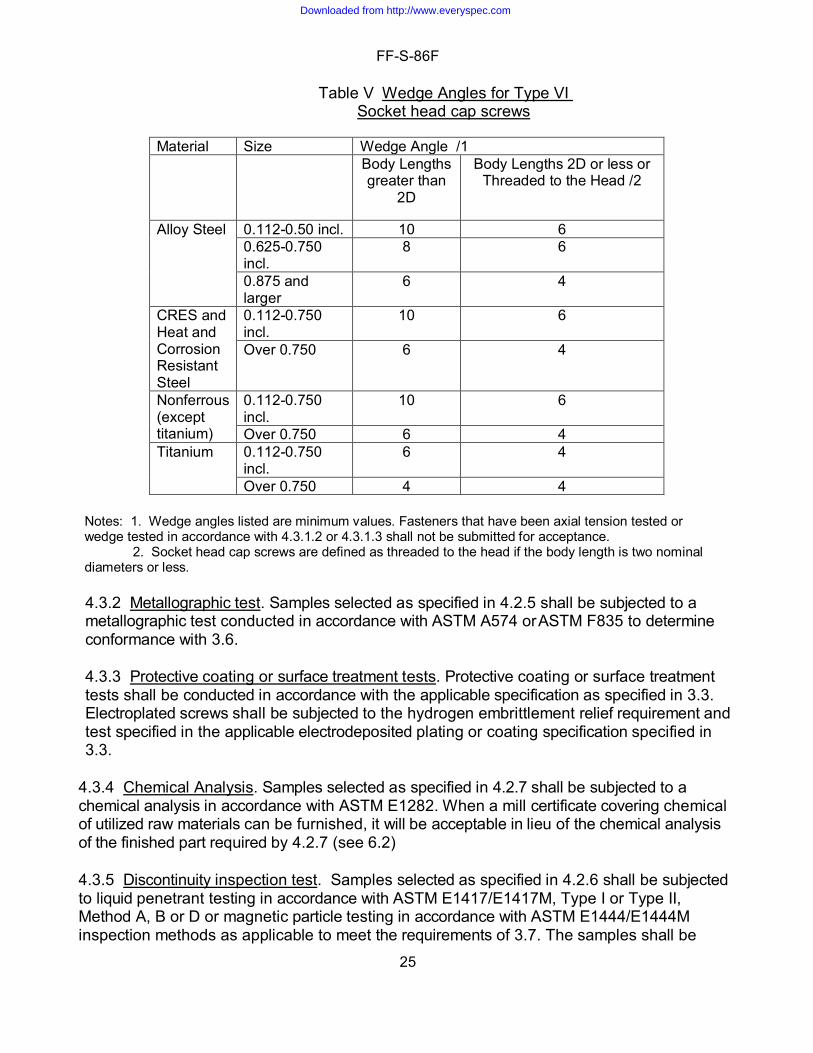
and button head fastener configurations, proof load shall be considered acceptable provided the fastener meets 80 percent of the prescribed types IV and VIII proof load of the fastener threaded area. 4.3.1.2.2 Yield test. Samples selected as specified in 4.2.5 shall be subjected to yield strength testing in accordance with ASTM F606/F606M. To allow for the critical nature of flat countersunk head and button head fastener configurations, types IV and VIII, the yield strength shall be considered acceptable provided the fastener meets 80 percent of the prescribed yield load of the fastener threaded area. Fasteners that have been yield strength tested in accordance with ASTM F606/606M utilizing either Method 2 or Method 2A shall not be used for wedge testing. 4.3.1.2.3 Axial tension test. Samples selected as specified in 4.2.5 shall be subjected to axial tension testing in accordance with ASTM F606/F606M. For flat countersunk head and button head fasteners, types IV and VIII, the fracture may extend or spread into the head of the fastener. To allow for the critical nature of flat countersunk head and button head fastener configurations, the axial tension strength shall be considered acceptable provided the fastener meets 80 percent of the prescribed axial tension load of the fastener threaded area. Minimum loads required to meet the tensile requirements are listed in tables VI and VII for corrosion resistant steel and heat and corrosion resistant steel screw only. 4.3.1.2.4 Tension testing of machined test specimen. For testing screws having tensile properties greater than can be measured on available test equipment, the body shall be turned down, concentric to the axis of the screw, to the largest practical gage dimension specified in ASTM F 606/F606M. These specimens shall be tested for tensile strength, yield strength, elongation and reduction in area in accordance with ASTM F 606/F606M. Testing is not required for any mechanical test attribute that does not have acceptance criteria for that attribute. Non-ferrous screws shall be excluded from the reduction in area requirement. For fasteners that are too short for preparing a machined test specimen in accordance with ASTM F606/F606M to support axial testing, longer length fasteners from the same lot, see 4.2.1, shall be produced to support turning down the body. The maximum length restriction per 4.2.1 for these longer fasteners does not apply. 4.3.1.3 Wedge tension test. When wedge tensile testing is required by Table IV, wedge testing shall be performed in accordance with ASTM F606/F606M, with wedge angles in accordance with Table V. Samples that have been yield tested shall not be used for wedge tensile testing. Samples that were used for proof testing may be used for wedge tensile testing, provided the fastener passed the proof test. Flat countersunk head and button head cap screws shall be exempt from the wedge tensile test.
Downloaded from http://www.everyspec.com
FF-S-86F
25
Table V Wedge Angles for Type VI Socket head cap screws
Material Size Wedge Angle /1 Body Lengths
greater than 2D
Body Lengths 2D or less or Threaded to the Head /2
Alloy Steel 0.112-0.50 incl. 10 6 0.625-0.750 incl.
8 6
0.875 and larger
6 4
CRES and Heat and Corrosion Resistant Steel
0.112-0.750 incl.
10 6
Over 0.750 6 4
Nonferrous (except titanium)
0.112-0.750 incl.
10 6
Over 0.750 6 4 Titanium 0.112-0.750
incl. 6 4
Over 0.750 4 4 Notes: 1. Wedge angles listed are minimum values. Fasteners that have been axial tension tested or wedge tested in accordance with 4.3.1.2 or 4.3.1.3 shall not be submitted for acceptance. 2. Socket head cap screws are defined as threaded to the head if the body length is two nominal diameters or less.
4.3.2 Metallographic test. Samples selected as specified in 4.2.5 shall be subjected to a metallographic test conducted in accordance with ASTM A574 or ASTM F835 to determine conformance with 3.6.
4.3.3 Protective coating or surface treatment tests. Protective coating or surface treatment tests shall be conducted in accordance with the applicable specification as specified in 3.3. Electroplated screws shall be subjected to the hydrogen embrittlement relief requirement and test specified in the applicable electrodeposited plating or coating specification specified in 3.3.
4.3.4 Chemical Analysis. Samples selected as specified in 4.2.7 shall be subjected to a chemical analysis in accordance with ASTM E1282. When a mill certificate covering chemical of utilized raw materials can be furnished, it will be acceptable in lieu of the chemical analysis of the finished part required by 4.2.7 (see 6.2) 4.3.5 Discontinuity inspection test. Samples selected as specified in 4.2.6 shall be subjected to liquid penetrant testing in accordance with ASTM E1417/E1417M, Type I or Type II, Method A, B or D or magnetic particle testing in accordance with ASTM E1444/E1444M inspection methods as applicable to meet the requirements of 3.7. The samples shall be
Downloaded from http://www.everyspec.com

FF-S-86F
26
metallurgically examined within a range from 15 to 200X magnification to determine the extent and depth of the discontinuities. NAVSEA Technical Publication T9074-AS-GIB-010/271 may be substituted for ASTM E1417/E1417M for liquid penetrant testing or E1444/E1444M for magnetic particle testing. QQ-N-286 Nickel-Copper-Aluminum alloy fasteners shall be inspected in accordance with T9074-AS-GIB-010/271. 4.3.6 Banded structure inspection. When a banded structure is observed of questionable acceptability, a minimum of 3 Knoop micro-hardness readings per test, in accordance with ASTM E384, shall be taken on the most predominate bands. The test load shall be 500 g, unless extremely thin bands are observed that will not permit an accurate 500 g test, in which case it is permissible to reduce the test load to as low as 50 g to obtain an accurate reading. Individual readings shall not exceed 470 HK. One test shall be conducted per heat. 4.3.7 Rounding of test results. Results of mechanical and chemistry tests shall be rounded in accordance with the rounding method of ASTM E29. Results of the chemistry analysis shall be rounded to the number of significant digits of the applicable test requirement. Tensile strength test values of up to 50,000 psi shall be rounded to the nearest 100 psi; test values over 50,000 psi and less than 100,000 psi shall be rounded to the nearest 500 psi; and test values over 100,000 psi shall be rounded to the nearest 1,000 psi. Elongation and reduction of area test values of up to 10 percent shall be rounded to the nearest 0.5 percent and test values over 10 percent shall be rounded to the nearest 1 percent. 5. Packaging. 5.1 Packaging. For acquisition purposes, the packaging requirements shall be as specified in the contract or order (see 6.2). When packaging of material is to be performed by DoD or in-house contractor personnel, these personnel need to contact the responsible packaging activity to ascertain packaging requirements. Packaging requirements are maintained by the Inventory Control Point's packaging activities within the Military Service or Defense Agency, or within the military service's system commands. Packaging data retrieval is available from the managing Military Department's or Defense Agency's automated packaging files, CD-ROM products, or by contacting the responsible packaging activity. 6. NOTES 6.1 Intended use. This specification covers externally threaded fasteners, which are designed to be driven into tapped holes with a hexagon or spline key or setter, in applications which require high strength precision products, compactness of design of the assembled parts, used in confined spaces or sinking of heads below surfaces into holes which fit the head. 6.2 Ordering data. Purchasers should select the preferred options permitted herein and include the following information in procurement documents:
a. Title, number and date of this specification. b. Type, material, size and length or standard part number (see 1.2, 1.2.1, 1.2.2 and
3.1).
Downloaded from http://www.everyspec.com

FF-S-86F
27
c. Title, number and date including part number specified in accordance with military document (see 6. 3).
d. Material certification, if required (see 3.1 and 4.3.4). e. Protective coating or surface treatment, if required (see 3.3) f. Cross drilling of cylindrical heads, if required (see 3.5.2). g. Thread series and class (see 3.5.4. 3).
6.3 Military Procurement. Items procured under this specification for military use are to be limited to the variety shown on the applicable Military Standards as specified herein. Cadmium plate fasteners are for replacement parts use only.
NAS1351 – Screw, Cap, Socket Head, Undrilled and Drilled, Plain and Self- Locking, Alloy Steel and Corrosion-Resisting Steel and Heat-Resistant Steel, UNRF-3A.
NAS1352 – Screw, Cap, Socket Head, Undrilled and Drilled, Plain and Self- Locking, Alloy Steel and Corrosion-Resistant Steel and Heat-Resistant Steel, UNRC-3A and UNRC-2A.
NASM16995 – Screw, Cap, Socket Head-Hexagon, Corrosion Resistant Steel, UNC-3A
NASM16996 – Screw, Cap, Socket Head-Hexagon, Corrosion Resistant Steel, UNF-3A
NASM21262 – Screws, Self Locking, 250° F, Cylindrical Head Hexagonal Wrenching Socket, Alloy Steel, 160 KSI FTU (Socket Head Cap Screws)
NASM21295 – Screws, Self Locking, 250° F, Cylindrical Head, Hexagonal Wrenching Socket, CRES 80 KSI FTU (Socket Head Cap Screws)
NASM24667 – Screw, Cap, Socket Head, Flat Countersunk, 82 deg., Alloy Steel, UNC-3A
NASM24671 – Screw, Cap, Socket-Head-Flat Countersunk, 82 deg., Corrosion-Resisting Steel, UNC-3A
NASM24673 – Screw, Cap, Socket Head, Hexagon, Drilled Corrosion- Resisting Steel (UNF-3A)
NASM24674 – Screw, Cap, Socket Head, Hexagon, Drilled Corrosion Resistant Steel (UNC-3A)
NASM24677 – Screw, Cap, Socket Head, Hexagon, Drilled Alloy Steel, (UNC-3A)
NASM24678 – Screw, Cap, Socket Head, Hexagon, Drilled, Alloy Steel, (UNF-3A)
MS24672 – Screw, Cap, Socket Head, Flat Countersunk, Corrosion Resisting Steel, UNF-3A
MS35455 – Screw, Cap, Socket Head-Hexagon, Alloy Steel, Uncoated, UNC-3A
MS35456 – Screw, Cap, Socket Head-Hexagon, Alloy Steel, Uncoated, UNF-3A (Inactive for New Design)
MS35457 – Screw, Cap, Socket Head Hexagon, Alloy Steel, Cadmium or Zinc, UNC-3A (Inactive for New Design)
Downloaded from http://www.everyspec.com

FF-S-86F
28
MS35458 – Screw, Cap, Socket Head-Hexagon, Alloy Steel, Cadmium or zinc, UNF-3A (Inactive for New Design)
MS35459 – Screw, Cap, Socket Head-Hexagon, Alloy Steel, Phosphate, UNC-3A (Inactive for New Design)
MS35460 – Screw, Cap, Socket Head-Hexagon, Alloy Steel, Phosphate, UNF-3A (Inactive for New Design)
MS35461 – Screw, Cap, Socket Head-Hexagon, Steel, Corrosion Resisting, Passivated, UNC-3A (Inactive for New Design)
MS51480 – Screw, Cap, Socket Head, Alloy Steel, UNF-3A (Inactive for New Design)
MS51484 – Screw, Cap, Socket Head, Alloy Steel, UNC-3A (Inactive for New Design)
6.3.1 Type I screws (1936 series). Type I screws (1936 series) are obsolete for new design. For procurement, it is recommended that the design be evaluated for use with type VI as replacement. 6.3.2 Types III, V, VII and IX screws. Types III, V, VII and IX are deleted from previous revisions of this specification. For procurement it is recommended that the design be evaluated for use with type IV, VI and VII as replacement. 6.3.3 Hazardous Materials. Cadmium coatings and coatings containing hexavalent chromium are obsolete and not to be used for new design. 6.4 Definitions of discontinuities. 6.4.1 Crack. A crack is a clean crystalline break passing through the grain or grain boundary without inclusion of foreign elements. 6.4.2 Seam. A seam is an elongated discontinuity in the metal caused by a defect which has been closed by rolling or forging mechanically, but not united. 6.4.3 Inclusion. An inclusion is particles of non-metallic impurities, usually oxides, sulfides, silicates and such, which are mechanically held in steel during solidification. 6.4.4 Lap. A lap is a surface defect appearing as a seam caused by folding over metal, fins or sharp corners, and then rolling or forging, but not welding them into the surface. 6.4.1 Nicks, Pits. Nicks and pits are a depression or indentation in the surface of the metal. 6.5 Subject term (key word) listing.
Button head cap screw Cylindrical head cap screw Flat countersunk cap screw Socket head cap screw
Downloaded from http://www.everyspec.com

FF-S-86F
29
Supersession data. This specification includes the requirements of FF‐S‐86E dated May 29, 1987 and Amendment 4 dated January 16. 1991, FF‐S‐86D dated 15 June 1971 and Amendment ‐1 dated 6 November 1972. Cross reference data between the types of screws covered by this specification and the types and styles of the preceding specifications, FF‐S‐86 dated 4 November 1953, FF‐S‐86A dated 16 May 1961, FF‐S‐86B dated 23 April 1964, FF‐S-86C dated 17 October 1967, and FF‐S‐86D dated 15 June 1971, are as follows:
Table 6.6 Supersession Reference Table
FF-S-86 FF-S-86A FF-S-86B, FF-S-86C, FF-S-86D, FF-S-86E
FF-S-86F
Type I, Style 11 Type I, 1936 Series
Type I None
Type I, Style 12 Type III, 1936 Series
Type III None 2/
Type I, Style 13 Type IV Type IV Type IV
Type I, Style 14 None 1/ None 1/ None 1/
None Type V Type V None 2/
None Type VI, 1960 Series
Type VI Type VI
None Type VII, 1960 Series
Type VII None 2/
None None Type VIII Type VIII
None None Type IX None 2/
1/ These specifications do not cover Type II, Style 11 of FF-S-86 since that type of fastener is an internal wrenching bolt. 2/ This specification does not cover Types I, III, V, VII and IX of FF-S-86E as these are either 1936 series or have an internal multiple spline socket head configuration. See 6.3.1 and 6.3.2.
Downloaded from http://www.everyspec.com

FF-S-86F
30
Table VI. Yield and tensile loads of corrosion resistant and heat and corrosion resistant steel head screws – coarse threads
1/ Do not use for new design. 2/ As = 3.1416[(D2/2) - (3H/16)]2 or As = 0.7854[D- 0.9743/(1/P)]2 as specified in ASME B1.1 3/ Values provided are for cylindrical head configuration. To allow for the critical nature of flat countersunk head and button head fastener configurations, the load shall be considered acceptable provided the full size fastener test meets 80 percent of the load (Types IV and VIII). 4/ Yield and tensile strength requirements were calculated by multiplying the yield and tensile strength minimum allowable stresses (of the corresponding machined specimen for the finished screw) by the tensile strength area of the threads.
Nominal Diameter
Threads per Inch
Tensile Stress Area
Corrosion Resistant Steel
Heat and Corrosion Resistant Steel
Yield Strength
Tensile Load
Yield Strength
Tensile Load
Lbs. min. 3/
Lbs. min. 3/
Lbs. min. 3/
Lbs. min. 3/
0.0730 64 0.00262 79.0 210 316 420 0.0860 56 0.00370 111.0 296 444 592 0.0990 48 0.00486 146.0 390 584 780 0.1120 40 0.00603 181.2 484 725 965 0.1380 32 0.00909 272.5 725 1,090 1,455 0.1640 32 0.01401 420 1,120 1,680 2,240 0.1900 24 0.01753 525 1,400 2,100 2,805 0.2500 20 0.03182 954 2,540 3,820 5,090 0.3125 18 0.05243 1,572 4,200 6,300 8,390 0.3750 16 0.07749 2,325 6,200 9,300 12,400 0.4375 14 0.10631 3,190 8,500 12,750 17,010 0.5000 13 0.14190 4,260 11,350 17,000 22,705 0.5625 12 0.18194 5,460 14,550 21,800 29,110 0.6250 11 0.22600 6,780 18,100 27,100 36,160 0.7500 10 0.33446 10,020 26,700 40,100 53,515 0.8750 9 0.46173 12,020 32,300 55,400 73,875 1.0000 8 0.60575 15,750 42,400 72,700 96,920 1.1250 7 0.76328 19,850 53,400 91,600 122,125 1.2500 7 0.96911 25,200 67,800 116,300 155,060 1.3750 6 1.15488 30,050 80,900 138,600 184,780 1.5000 6 1.40525 36,500 98,400 168,600 224,840
Downloaded from http://www.everyspec.com

FF-S-86F
31
Table VII. Yield and tensile loads of corrosion resistant and heat and corrosion resistant steel head screws – fine threads for full-sized specimens only
Nominal size
Threads per inch
Tensile stress area 2/
Corrosion Resistant Steel
Heat and Corrosion Resistant Steel
Yield Strength
Tensile Load
Yield Strength
Tensile Load
Lbs. min. 3/
Lbs. min. 3/
Lbs. min. 3/
Lbs. min. 3/
0.0600 80 0.00180 54.0 144 216 288 0.0730 72 0.00278 83.4 222 334 444 0.0860 64 0.00393 118.2 316 472 630 0.0990 56 0.00523 157.0 418 628 836 0.1120 48 0.00660 198.5 530 794 1,060 0.1250 44 0.00831 249.5 665 998 1,330 0.1380 40 0.01014 304.5 810 1,220 1,620 0.1640 36 0.01473 442 1,180 1,770 2,360 0.1900 32 0.01999 600 1,600 2,400 3,200 0.2500 28 0.03637 1,092 2,910 4,350 5,820 0.3125 24 0.05807 1,740 4,640 6,950 9,300 0.3750 24 0.08783 2,635 7,020 10,500 14,050 0.4375 20 0.11872 3,560 9,500 14,200 19,000 0.5000 20 0.15995 4,800 12,800 19,200 25,600 0.5625 18 0.20298 6,090 16,250 24,400 32,500 0.6250 18 0.25596 7,680 20,500 30,700 41,000 0.7500 16 0.37296 9,700 26,100 44,800 59,700 0.8750 14 0.50947 13,240 35,600 61,100 81,400 1.0000 12 0.66304 17,250 46,400 79,600 106,100 1.1250 12 0.85572 22,250 59,900 102,700 137,000 1.2500 12 1.07295 27,900 75,100 128,800 171,700 1.3750 12 1.31471 34,200 92,100 157,800 210,400 1.5000 12 1.58102 41,100 110,700 189,700 253,000 1.0000 14NS 0.67989 17,700 47,500 81,500 108,600
1/ Do not use for new design. 2/ As = 3.1416[(D2/2) - (3H/16)]2 or As = 0.7854[D- 0.9743/(1/P)]2 as specified in ASME B1.1 3/ To allow for the critical nature of flat countersunk head and button head fastener configurations, the load shall be considered acceptable provided the fastener meets 80 percent of the load (Types IV and VIII). 4/ Yield and tensile strength requirements were calculated by multiplying the yield and tensile strength minimum allowable stresses (of the corresponding machined specimen for the finished screw) by the tensile strength area of the threads.
Downloaded from http://www.everyspec.com

FF-S-86F
32
Table VIII. Mechanical properties of non-ferrous screws for full-sized specimens only
Material
Applicable document
Composition, class or alloy number
Condition or temper of bar
Ultimate tensile Strength PSI min. unless shown as a range
Yield strength PSI min. 2/
Elongation percent min. 1/
Hardness 4/
Manganese Bronze
ASTM F468 or
ASTM B138/B138M
Cu 675
UNS C67500
O60 – soft anneal
55 ,000 – 85,000
22,000 2 /
20 HRB 60-90
Nickel Aluminum Bronze
ASTM B150/B150M
UNS C63200 TQ50 – quench
hardened and temper
90,000 50,000 2 / 15 HRB 96 min
Phosphor Bronze
ASTM F468 or
ASTM B139/B139M
Cu 510
C51000
H04/Hard
80,000 (Dia. under .250)
70,000 (Dia. = .250 to .500)
60,000 (Dia. = over .500 to 1.000)
55,000 (Dia. = 1.000 to 3.000)
50,000 (Dia. = over 3.000)
35,000 2/
Not Specified
13
15
18
18
HRB 60-95
Silicon Bronze
ASTM F468 or
ASTM B98/B98M
or ASTM B99/B99M
Cu 651 UNS
C65100
UNS C65100
04H – Hard
01H – Quarter-hard
60,000 40,000 2 / 10 HRB 60-95
Naval Brass ASTM F468 or
ASTM B21/ B21M
Cu 464
UNS C46400
H02 - Half-Hard or O50 Light
Annealed
50,000 27,000 2 / 22 (Dia. = .500 & under 25 (Dia. = over .500)
HRB 55-75
Downloaded from http://www.everyspec.com

FF-S-86F
33
Nickel Copper Alloy
ASTM F468 or
QQ-N-281
Ni 400
Ni 405
Class A
Hot Finished or Cold Drawn
80,000 40,000 2 / 20 HRB 75 – HRC 25
Nickel- Copper-
Aluminum Alloy
QQ-N-286
Ni 500 N05500 Annealed
and Age Hardened
130,000 90,000 (Dia. = Under 1.000) 85,000 (Dia. = 1.000 & Over)
2 /
20 HRC 24-35
Inconel 625 5/
ASTM F468 Or
ASTM B446, Grade 1
Ni 625 N06625
120,000 60,000 30 HRB 85 – HRC 35
Inconel 686
ASTM F468 Or
ASTM B574
Ni 686 N06686 Hot or Cold
Worked and Annealed
120,000 - 165,000 85,000
20 HRC 21 - 45
Titanium ASTM F468 Or
ASTM B348
TI 23 R56407 Hot Worked
or Cold Finished
120,000 - 165,000 110,000 12 HRC 25 - 36
1/ In 4D gage length. 2/ 0.2 percent offset unless otherwise cited in referenced standard. 3/ For arbitration purposes, Ultimate Tensile Strength takes precedence over Hardness. 4/ Due to differences in mechanical properties for non-ferrous materials between Industry Standards and FF-S-86, new designs are encouraged to use SAE J2295. 5/ Finished fasteners shall be furnished in the annealed condition.
Downloaded from http://www.everyspec.com

FF-S-86F
34
1/ Obsolete for new design (see 6.3.1). For procurement, it is recommended that the design be evaluated for use with type VI as replacement. Internal multiple spline fasteners should be replaced with hex configuration for types III. V. VIII and IX of the same head configuration.
Figure 7. Socket-head screw types.
Types Drives Heads Type I 1/
CYLINDRICAL
Type IV 1/
FLAT
Type VI, 1/
CYLINDRICAL
Type VIII 1960 Series 1/
BUTTON
Downloaded from http://www.everyspec.com

FF-S-86F
35
Military Interest: Custodians: Preparing Activity: Army – AR DLA – IS Navy – SH
Review Activities: (Project: 5305-2018-001) Army – AT, AV, EA, MI Navy – MC Air Force – 71
NOTE: The activities listed above were interested in this document as of the date of this document. Since organizations and responsibilities can change, you should verify the currency of the information above using the ASSIST Online database at https://assist.dla.mil.
Downloaded from http://www.everyspec.com