indentation of spherical and conical punches into...
TRANSCRIPT
Indentation of spherical and conical punches into piezoelectric half-space with frictional sliding:Applications to scanning probe microscopy
Arty Makagon* and Mark KachanovDepartment of Mechanical Engineering, Tufts University, Medford, Massachusetts 02155, USA
Sergei V. KalininMaterials Sciences and Technology Division, Oak Ridge National Laboratory, Oak Ridge, Tennessee 37831, USA
Edgar Karapetian†
Department of Mathematics & Computer Science, Suffolk University, Boston, Massachusetts, 02114, USA�Received 26 December 2006; revised manuscript received 20 April 2007; published 21 August 2007�
A proper quantitative interpretation of scanning probe microscopy �SPM� experiments requires solutions forboth normal and tangential indentations of punches into a piezoelectric material. Such indentation solutions,their dependence on the indenter shape, and implications for SPM are considered here. More specifically,indentation of the spherical and conically sharp indenters into a piezoelectric half-space accompanied byfrictional sliding is addressed. The tangential part of the problem, which involves friction, is solved to comple-ment the solution of the normal indentation problem obtained earlier. Exact stiffness relations between verticalload, tangential displacement, and material properties are obtained. The piezoelectric coupling is found to havea relatively weak effect on lateral contact stiffness. In contrast, the contact area depends noticeably on thetangential effects. The full electroelastic fields are derived in elementary functions and their implications arediscussed.
DOI: 10.1103/PhysRevB.76.064115 PACS number�s�: 68.35.Gy, 77.84.�s, 77.65.�j, 68.37.Tj
I. INTRODUCTION
The ubiquitous feature of polar inorganic materials havingvarious orientation patterns, as well as phase-separatingpolymers and biological systems, is the formation of orderednanoscale regions exhibiting dissimilar electromechanicalproperties. Examples include ferroelectric and ferroelasticdomains in single crystals, grains in piezoelectric and ferro-electric ceramics, phase-separated regions in electroactivepolymers, composite structures of connective and calcifiedtissues, and biopolymers. Understanding and optimization ofproperties of these materials presents three challenges: �a�real-space imaging of material microstructure and identifica-tion of constitutive elements down to the nanometer scale,�b� measurement of local electromechanical propertieswithin a single phase, and �c� understanding the interfaceproperties between the constitutive elements.
Electron microscopy methods, including transmission andscanning electron microscopy, probe local structure based onthe differences in local chemical composition and topogra-phy. However, they provide no information on the mechani-cal properties. In the last decade, several scanning probe mi-croscopy �SPM� techniques including atomic force acousticmicroscopy1 �AFAM�, scanning local accelerationmicroscopy2 �SLAM�, force modulation microscopy3
�FMM�, hybrid nanoindentation,4 and ultrasonic forcemicroscopy5 �UFM� were developed to study the elastic ma-terial properties on the nanoscale. Conventional intermittentmode atomic force microscopy provides a wealth of informa-tion on the local mechanical properties in the phase image.6
In parallel, a number of SPM techniques, most notably pi-ezoresponse force microscopy7 �PFM�, were developed toanalyze the local electromechanical properties.
PFM has found a broad applicability for the characteriza-tion of electromechanically active materials, including imag-ing domain structures in ferroelectric perovskites, mappingthe nanostructure of ferroelectric polymers and biopolymers,and local spectroscopy and polarization switching. In the de-cade since its invention, PFM has become the primary toolfor ferroelectric materials characterization. A recent applica-tion of PFM to imaging of biological systems suggests theenormous potential of this technique.8–10
These considerations necessitate a fundamental quantita-tive analysis of contact mechanisms involved in signal gen-eration in PFM, including the effects of lateral tip motionduring scanning. This constitutes the primary motivation forthe present work. In particular, we address the problem ofpiezoelectric indentation accompanied by frictional sliding,the motivation being that �i� the sliding motion of the tip onthe surface is the inherent feature of contact-mode SPM ex-periments and �ii� in a number of observations of ferroelec-tric domains by lateral force microscopy it has been reportedthat local friction signal provided the contrast that character-izes domain structures. In particular, Eng et al.11 demon-strated that domains in triglycine sulphate �TGS� can be eas-ily visualized in lateral force microscopy �LFM� images,while no contrast is seen in topographic images. Similarly,LFM study of TGS and guanidinium aluminum sulfatehexahydrate �GASH� by Bluhm et al.12 found that frictioncoefficients were scan-direction and polarization dependent.For the GASH crystal, the LFM contrast was found to becaused by the structural differences between surface domainsof different orientations, since the contrast did not inverteven if relatively strong bias of 10 V was applied betweenthe sample and the surface. Finally, the disappearance ofcontrast with temperature across the phase transition was in-
PHYSICAL REVIEW B 76, 064115 �2007�
1098-0121/2007/76�6�/064115�14� ©2007 The American Physical Society064115-1
terpreted by Correia et al.13 as the indicator of its ferroelec-tric origin.
These studies suggest that the observed contrast is derivedfrom either chemical differences between surfaces of do-mains with opposite polarity or intrinsic differences in bias-dependent contact mechanics. To resolve this issue, we con-sider bias effects on the lateral contact mechanics in SPM,and this leads to the problem of indentation of a piezoelectrichalf-space by a rigid punch accompanied by frictional slid-ing. Two punch geometries are analyzed: the spherical andthe conical ones.
II. FORMULATION OF THE INDENTATION PROBLEMFOR THE PIEZOELECTRIC HALF-SPACE
Problems of piezoelectric indentation present a difficultmathematical challenge. Several solutions for the normal in-dentation, without friction, have been obtained for thespherical, conical, and flat indenter geometries �Chen14 andChen and Ding15�. In these results, however, the combina-tions of electroelastic constants in whose terms the fields areexpressed are not identified. In works of Giannakopoulos andSuresh16 and Giannakopoulos,17 three punch geometrieswere considered: spherical, conical, and flat circular. In theseworks, electroelastic fields were given in the closed form onthe boundary of the half-space only. Inside the material thefields are given in integral form, which makes it difficult todifferentiate between bias and stress effects. Utilizing a re-cently established correspondence principle �Karapetian etal.18� between the elastic and piezoelectric problems fortransversely isotropic materials, Kalinin et al.19 and Karape-tian et al.20 gave the closed-form piezoelectric solution forthe spherical, conical, and flat punches.
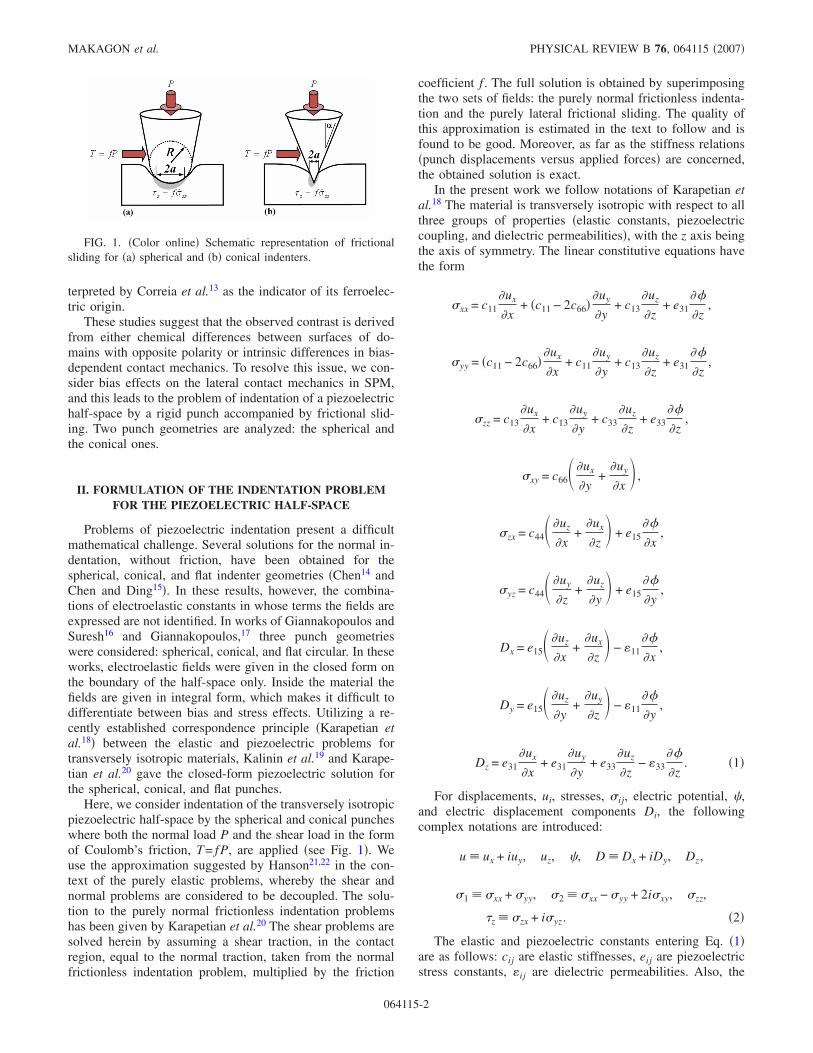
Here, we consider indentation of the transversely isotropicpiezoelectric half-space by the spherical and conical puncheswhere both the normal load P and the shear load in the formof Coulomb’s friction, T= fP, are applied �see Fig. 1�. Weuse the approximation suggested by Hanson21,22 in the con-text of the purely elastic problems, whereby the shear andnormal problems are considered to be decoupled. The solu-tion to the purely normal frictionless indentation problemshas been given by Karapetian et al.20 The shear problems aresolved herein by assuming a shear traction, in the contactregion, equal to the normal traction, taken from the normalfrictionless indentation problem, multiplied by the friction
coefficient f . The full solution is obtained by superimposingthe two sets of fields: the purely normal frictionless indenta-tion and the purely lateral frictional sliding. The quality ofthis approximation is estimated in the text to follow and isfound to be good. Moreover, as far as the stiffness relations�punch displacements versus applied forces� are concerned,the obtained solution is exact.
In the present work we follow notations of Karapetian etal.18 The material is transversely isotropic with respect to allthree groups of properties �elastic constants, piezoelectriccoupling, and dielectric permeabilities�, with the z axis beingthe axis of symmetry. The linear constitutive equations havethe form
�xx = c11�ux
�x+ �c11 − 2c66�
�uy
�y+ c13
�uz
�z+ e31
��
�z,
�yy = �c11 − 2c66��ux
�x+ c11
�uy
�y+ c13
�uz
�z+ e31
��
�z,
�zz = c13�ux
�x+ c13
�uy
�y+ c33
�uz
�z+ e33
��
�z,
�xy = c66� �ux
�y+
�uy
�x� ,
�zx = c44� �uz
�x+
�ux
�z� + e15
��
�x,
�yz = c44� �uy
�z+
�uz
�y� + e15
��
�y,
Dx = e15� �uz
�x+
�ux
�z� − �11
��
�x,
Dy = e15� �uz
�y+
�uy
�z� − �11
��
�y,
Dz = e31�ux
�x+ e31
�uy
�y+ e33
�uz
�z− �33
��
�z. �1�
For displacements, ui, stresses, �ij, electric potential, �,and electric displacement components Di, the followingcomplex notations are introduced:
u � ux + iuy, uz, �, D � Dx + iDy, Dz,
�1 � �xx + �yy, �2 � �xx − �yy + 2i�xy, �zz,
�z � �zx + i�yz. �2�
The elastic and piezoelectric constants entering Eq. �1�are as follows: cij are elastic stiffnesses, eij are piezoelectricstress constants, �ij are dielectric permeabilities. Also, the
FIG. 1. �Color online� Schematic representation of frictionalsliding for �a� spherical and �b� conical indenters.
MAKAGON et al. PHYSICAL REVIEW B 76, 064115 �2007�
064115-2
following piezoelectric clusters are widely used: � j*=c44
�1+mj*�+e15kj
*, � j*=e15�1+mj
*�−�11kj* �j=1,2 ,3�, where mj
*,kj
* are defined by the following relations:
mj* =
�c11 j*2 − c44���33 − j
*2�11� + j*2�e15 + e31�2
�e33 − j*2e15��e15 + e31� + �c13 + c44���33 − j
*2�11�,
kj* =
�c11 j*2 − c44��e33 − j
*2e15� − j*2�c13 + c44��e15 + e31�
�e33 − j*2e15��e15 + e31� + �c13 + c44���33 − j
*2�11�,
�3�
where j*2= j are roots of the cubic equation:
A j3 − B j
2 + C j − D = 0 �4�
with coefficients
A = c11�c44�11 + e152 � ,
B = c44�c11�33 + �e15 + e31�2� + �11�c11c33 + c442 − �c13 + c44�2�
+ 2e15�c11e33 − �c13 + c44��e15 + e31�� + c44e152 ,
C = c33�c44�11 + �e15 + e31�2� + �33�c11c33 + c442 − �c13 + c44�2�
+ 2e33�c44e15 − �c13 + c44��e15 + e31�� + c11e332 ,
D = c44�c33�33 + e332 � . �5�
The cubic equation �4� is a consequence of the algebraicequations �Karapetian et al.23�
c44 + mj*�c13 + c44� + kj
*�e15 + e31�c11
=mj
*c33 + kj*e33
mj*c44 + �c13 + c44� + kj
*e15
=mj
*e33 − kj*�33
mj*e15 + �e15 + e31� − kj
*�11
= j*2 � j, 4
* = �c44/c66. �6�
The following clusters of the piezoelectric constants are de-fined:
G1* = �* + �e15
2 + c44�11��*H* =4
*
2�c44+
�*
2�j=1
3� j
*aj*
j*2
,
G2* = �* − �e15
2 + c44�11��*H* =4
*
2�c44−
�*
2�j=1
3� j
*aj*
j*2
,
H* =1
2��e152 + c44�11�
j=1
3� j
*aj*
j*2
,
�* = j=1
3aj
*
j* = k1
*�m3* − m2
*� + k2*�m1
* − m3*� + k3
*�m2* − m1
*� ,
a1* = 1
*��1 + m2*�k3
* − �1 + m3*�k2
*�, 1 → 2 → 3 → 1, �7�
and the geometric parameters �j=1,2 ,3�
2l1j�z� = ��a + �2 + zj2 − ��a − �2 + zj
2,
2l2j�z� = ��a + �2 + zj2 + ��a − �2 + zj
2,
zj = z/ j* �8�
are used. Of the clusters �7�, the quantity G1* plays a particu-
larly important role; as discussed in Sec. VI A, it is the onlycluster of piezoelectric constants that enters the stiffness re-lations. We will also utilize the following relations:
j=1
3� j
*aj*
j* =
j=1
3� j
*aj*
j* = 0. �9�
III. SOLUTION FOR THE SPHERICAL INDENTER
The shear traction in the contact region is taken as a co-efficient of friction, f = fx+ ify, multiplied by the normal con-tact pressure P, so that T=Tx+Ty = fP. Thus, the boundaryconditions for the shear problem are given as
�zz = 0, 0 � � � , �z = f��zz, � a ,
�z = 0, � a, Dz = 0, 0 � � � , �10�
for 0���2�, where ��zz is taken from the problem of fric-tionless normal indentation; thus,
�z = f��zz =3P�fx + ify�
2�a3�a2 − 2. �11�
Note that the result used in stating Eq. �11�—the normaltraction under the punch for frictionless normal indentationof a piezoelectric half-space—is identical to the correspond-ing result for the purely elastic isotropic material, earlier ob-tained by Harding and Sneddon.24
A. Full electroelastic fields
The solution is obtained via the correspondence principlethat allows constructing the full piezoelectric solution fromthe purely elastic one. Utilizing the purely elastic solution ofHanson22 and the correspondence Table 2 of Karapetian etal.18 we obtain coupled electroelastic fields in cylindrical co-ordinates ,� ,z as follows:
INDENTATION OF SPHERICAL AND CONICAL PUNCHES… PHYSICAL REVIEW B 76, 064115 �2007�
064115-3
u =3P�G2
* − G1*�
8a3�* j=1
3aj
*
j* f�� 2
2− a2 − zj
2�arcsin� l1j
� +
�2a2 − 3l1j2 �� 2 − l1j
2 �1/2
2l1j� + f̄e2i��−
4a3zj
3 2 + 2
4arcsin� l1j
�
+ �8a4 + a2 2 − l1j2 �zj
2 +5
2 2 + 5a2�� � 2 − l1j
2 �1/2
6 2l1j�
−3P�G2
* + G1*�
8a3 f�� 2
2− a2 − z4
2�arcsin� l14
� +
�2a2 − 3l142 �� 2 − l14
2 �1/2
2l14� − f̄e2i��−
4a3z4
3 2 + 2
4arcsin� l14
�
+ �8a4 + a2 2 − l142 �z4
2 +5
2 2 + 5a2�� � 2 − l14
2 �1/2
6 2l14� ,
uz =3P�G2
* − G1*�
8a3�* � f̄ei� + fe−i�� j=1
3mj
*aj*
j*2 �− zj arcsin� l1j
� + �a2 − l1j
2 �1/2�1 −l1j2 + 2a2
3 2 � +2a3
3 2� ,
� =3P�G2
* − G1*�
8a3�* � f̄ei� + fe−i�� j=1
3kj
*aj*
j*2 �− zj arcsin� l1j
� + �a2 − l1j
2 �1/2�1 −l1j2 + 2a2
3 2 � +2a3
3 2� ,
�1 =3P�G2
* − G1*�
4a3�* � f̄ei� + fe−i�� j=1
3 �c66 −� j
*
j*2� aj
*
j*�− arcsin� l1j
� +
l1j� 2 − l1j2 �1/2
2 � ,
�2 =3Pc66�G2
* − G1*�
2a3�* j=1
3aj
*
j* fei��
2arcsin� l1j
� −
l1j� 2 − l1j2 �1/2
2 � − f̄e3i�� 4zj
3 3 ��l1j2 + 2a2��a2 − l1j
2 �1/2 − 2a3� +l1j3 � 2 − l1j
2 �1/2
3 � −
3Pc66�G2* + G1
*�2a3 fei��
2arcsin� l14
� −
l14� 2 − l142 �1/2
2 � + f̄e3i�� 4z4
3 3 ��l142 + 2a2��a2 − l14
2 �1/2 − 2a3� +l143 � 2 − l14
2 �1/2
3 � ,
�zz =3P�G2
* − G1*�
8a3�* � f̄ei� + fe−i�� j=1
3� j
*aj*
j* �− arcsin� l1j
� +
l1j� 2 − l1j2 �1/2
2 � ,
�z =3P�G2
* − G1*�
4a3�* j=1
3� j
*aj*
j*2 f�− zj arcsin� l1j
� + �a2 − l1j
2 �1/2� − f̄e2i�2a3 − �l1j2 + 2a2��a2 − l1j
2 �1/2
3 2 −
3P
4�a3 f�− z4 arcsin� l14
� + �a2 − l14
2 �1/2� + f̄e2i�2a3 − �l142 + 2a2��a2 − l14
2 �1/2
3 2 ,
Dz =3P�G2
* − G1*�
8a3�* � f̄ei� + fe−i�� j=1
3� j
*aj*
j* �− arcsin� l1j
� +
l1j� 2 − l1j2 �1/2
2 � ,
D =3P�G2
* − G1*�
4a3�* j=1
3� j
*aj*
j*2 f�− zj arcsin� l1j
� + �a2 − l1j
2 �1/2� − f̄e2i�2a3 − �l1j2 + 2a2��a2 − l1j
2 �1/2
3 2 −
3P
4�a3
e15
c44 f�− z4 arcsin� l14
� + �a2 − l14
2 �1/2� + f̄e2i�2a3 − �l142 + 2a2��a2 − l14
2 �1/2
3 2 . �12�
MAKAGON et al. PHYSICAL REVIEW B 76, 064115 �2007�
064115-4

The radius a of the contact zone is obtained from the stiff-ness relation �16� that relates the penetration depth and ap-plied force.
The structure of selected obtained fields is illustrated inFigs. 2 and 3, using material constants for barium titanate�BaTiO3� and lithium niobate �LiNbO3�. The relevant clus-ters of material parameters are given in Table I.
Both the tangential displacement ux and the shear stress�zx are maximal directly under the center of the indenter anddecrease with increasing x and z. Lines of equal level for uxattain maximum distance from the origin along the x axiswhereas similar lines for �zx in between the x and z axes.Figure 2 shows that the indenter-induced field of the electricdisplacement Dx is much weaker for LiNbO3 as compared toBaTiO3, for the reason that the piezoelectric constants eij arelarger for the latter.
As illustrated in Fig. 3�a� �as an enlargement of the zonelabeled “�” in Fig. 2�e�, the maximal value of Dx for BaTiO3is achieved at certain depth below the surface. This feature isnot observed for LiNbO3 �Fig. 3�b�, as an enlargement of thezone labeled � in Fig. 2�f��. This difference in behavior ofthe electric displacement field in the two materials is due to
the effect of the cluster of material constantsc44
e15 j=1
3 � j*aj
*
j*2 that
enters terms A and C in the expression for Dx along the z axisunder the center of the indenter � =0�:
�13�This is illustrated by Fig. 4, which shows terms A , B, and
C in Eq. �13� as well as the sum of terms A and B for bothmaterials as a function of material depth. The term C is con-stant and thus is not a determining factor in the behavior ofthe electric displacement field.
The difference between the behavior of the two materialsis caused by the fact that, for BaTiO3, the ratio �slope ofdecrease of term A�/�slope of increase of term B� is largerthan 1 near the surface �z=0� and decreases to values smaller
TABLE I. Relevant clusters of material constants.
Material G1* �1/GPa� G2
* �1/GPa�
BaTiO3 4.913 E-3 1.316 E-3
LiNbO3 4.047 E-3 6.358 E-3
FIG. 2. �Color online� Two-dimensional spatial distribution of the x component of tangential displacement, ux �a, b�, x component ofshear stress, �xz �c�, �d�, and tangential x component of electric displacement, Dx �e�, �f� for spherical indenter geometry for BaTiO3 �a�, �c�,�e� and LiNbO3 �b�, �d�, �f�. Regions � in �c�, �f� are scaled up and presented in Fig. 3 below. Indentation parameters are: indentation forceP=1.54 �N; contact radius a=3 nm; coefficient of friction, f =0.3; and coordinate �=0.
FIG. 3. �Color online� 10� enlargement of region � in the spa-tial distribution of the tangential x component of electric displace-ment, Dx in Figs. 2�e� and 2�f� for BaTiO3 �a� and LiNbO3 �b�.Numerical distribution of the contour plot has been more finelydiscretized.
INDENTATION OF SPHERICAL AND CONICAL PUNCHES… PHYSICAL REVIEW B 76, 064115 �2007�
064115-5

than 1 with increasing depth. This results in their sum beingnegative at some depth below the surface and positive atincreasing depths asymptotically approaching the value ofthe term C, such that Eq. �13� goes to zero at infinite depth.Conversely, for LiNbO3, the above-mentioned material prop-erty cluster, being opposite in sign to the one for BaTiO3,causes the term A to increase with depth such that the sum ofterms A and B is always positive, thereby maximizing Eq.�13� at the surface �z=0�.
B. Electroelastic fields at the boundary of the half-space
At the boundary of the half-space �z=0�, the solution ob-tained above reduces to the following formulas �Eq. �9� isutilized�.
�A� At �a �l1j = ; l2j =a�,
u =3P�
8a3 �G1*f�a2 −
2
2� + G2
* f̄e2i� 2
4� ,
uz =�G2
* − G1*�P
4�*a3 �a3 − �a2 − 2�3/2
�� f̄ei� + fe−i��
j=1
3mj
*aj*
j*2 ,
� =�G2
* − G1*�P
4�*a3 �a3 − �a2 − 2�3/2
�� f̄ei� + fe−i��
j=1
3kj
*aj*
j*2 ,
�1 =3�G1
* − G2*��P
8�*a3 � f̄ei� + fe−i�� j=1
3 �c66 −� j
*
j*2� aj
*
j* ,
�2 = −3P�G1
*c66
4a3 fei�,
�zz = 0,
�z = −3P
2�a3 f�a2 − 2�1/2,
Dz = 0,
D =3P
4�a3��G2* − G1
*���*
j=1
3� j
*aj*
j*2 −
e15
c44� f�a2 − 2�1/2
+ � �G2* − G1
*���*
j=1
3� j
*aj*
j*2 +
e15
c44�
� f̄e2i� � 2 + 2a2��a2 − 2�1/2 − 2a3
3 2 . �14�
�B� At �a �l1j =a; l2j = �,
u =3PG1
*
4a3 � f�a2 − 2
2�arcsin�a
� +
a� 2 − a2�1/2
2�
+3PG2
*
4a3 � f̄e2i�� 2
4�arcsin�a
�
+ a�2a2 − 2�� 2 − a2�1/2
4 2 � ,
uz =�G2
* − G1*�P
4�* � f̄ei� + fe−i��
j=1
3mj
*aj*
j*2 ,
� =�G2
* − G1*�P
4�* � f̄ei� + fe−i��
j=1
3kj
*aj*
j*2 ,
�1 =3�G2
* − G1*�P
4�*a3 � f̄ei� + fe−i�� j=1
3 �c66 −� j
*
j*2�
�aj
*
j*�a� 2 − a2�1/2
2 − arcsin�a
�� ,
�2 =3Pc66
a3 G1*fei��a� 2 − a2�1/2
2 −
2arcsin�a
��
+ G2* f̄e3i��a3�a2 − 2�1/2
3 � ,
FIG. 4. �Color online� Behavior of terms A, B, and C entering Eq. �13� and the sum of terms A and B for BaTiO3 �a� and LiNbO3 �b�.
MAKAGON et al. PHYSICAL REVIEW B 76, 064115 �2007�
064115-6
�zz = 0,
�z = 0,
Dz = 0,
D =Pf̄e2i�
2� 2 ���G1* − G2
*��*
j=1
3� j
*aj*
j*2 −
e15
c44� . �15�
The stiffness relation between the lateral displacement atthe punch center u0 and the tangential force takes the form
T = Pf =8a
3G1*�
u0. �16�
This piezoelectric relation is identical to the one for thepurely elastic case, provided the cluster G1
* replaces the com-bination of elastic constants G1 �see, for example,Fabrikant25�.
IV. SOLUTION FOR THE CONICAL INDENTER
Boundary conditions for the spherical indenter apply tothe indentation of a cone as well. Based on the solution forthe normally loaded conical punch indenting a piezoelectrichalf-space, the shear traction in the contact zone �related tothe normal traction by Coulomb’s friction law� is given by
�z = f��zz =P�fx + ify�
�a2 cosh−1�a
� . �17�
Importantly, the normal traction distribution in the piezoelec-tric case, which enters the formula above, is the same as inthe purely elastic problem for the isotropic half-space ob-tained by Sneddon.26 This fact is discussed in Sec. V of thepresent work.
A. Full electroelastic fields
Employing the elastic solution of Hanson21 and utilizingthe Correspondence Table 2 of Karapetian et al.18 yieldselectroelastic fields in cylindrical coordinates ,� ,z:
u =P�G2
* − G1*�
2a2�* j=1
3aj
*
j* f�− a arcsin� l1j
� − �l2j
2 − a2�1/2 + zjln�l2j + �l2j2 − 2�1/2�
+ � 2 + zj2�1/2 − zjln�zj + � 2 + zj
2�1/2�� + f̄e2i��−a2zj
2 +� 2 + zj
2�3/2 + �4a2 − 3l1j2 − l2j
2 ��l2j2 − a2�1/2
3 2 �
−P�G2
* + G1*�
2a2 f�− a arcsin� l14
� − �l24
2 − a2�1/2 + z4ln�l24 + �l242 − 2�1/2� + � 2 + z4
2�1/2 − z4ln�z4 + � 2 + z42�1/2��
− f̄e2i��−a2z4
2 +� 2 + z4
2�3/2 + �4a2 − 3l142 − l24
2 ��l242 − a2�1/2
3 2 � ,
uz =P�G2
* − G1*�
2a2�* � f̄ei� + fe−i��j=1
3mj
*aj*
j*2 �
2ln�l2j + �l2j
2 − 2�1/2� −
2ln�zj + � 2 + zj
2�1/2� +a2
2 −
zj� 2 + zj2�1/2
2
+� l2j − 2al1j��l2j
2 − 2�1/2
2 2 � ,
� =P�G2
* − G1*�
2a2�* � f̄ei� + fe−i��j=1
3kj
*aj*
j*2 �
2ln�l2j + �l2j
2 − 2�1/2� −
2ln�zj + � 2 + zj
2�1/2� +a2
2 −
zj� 2 + zj2�1/2
2
+� l2j − 2al1j��l2j
2 − 2�1/2
2 2 � ,
�1 =P�G2
* − G1*�
a2�* � f̄ei� + fe−i��j=1
3 �c66 −� j
*
j*2� aj
*
j*
�l2j2 − a2�1/2 − � 2 + zj
2�1/2
,
INDENTATION OF SPHERICAL AND CONICAL PUNCHES… PHYSICAL REVIEW B 76, 064115 �2007�
064115-7
�2 =Pc66�G2
* − G1*�
a2�* j=1
3aj
*
j* fei� � 2 + zj
2�1/2 − �l2j2 − a2�12
+ f̄e3i�� �12l1j
2 + 4l2j2 − 3 2 − 16a2��l2j
2 − a2�1/2
3 3 +4a2zj
3
−4zj
2 + 4 + 5zj2 2
3 3� 2 + zj2�1/2 � −
Pc66�G2* + G1
*�a2 fei� � 2 + z4
2�1/2 − �l242 − a2�1/2
− f̄e3i�� �12l14
2 + 4l242 − 3 2 − 16a2��l24
2 − a2�1/2
3 3
+4a2z4
3 −4z4
2 + 4 + 5z42 2
3 3� 2 + z42�1/2 � ,
�zz =P�G2
* − G1*�
2a2�* � f̄ei� + fe−i��j=1
3� j
*aj*
j*
�l2j2 − a2�1/2 − � 2 + zj
2�12
,
�z =P�G2
* − G1*�
2a2�* j=1
3� j
*aj*
j*2 f ln
l2j + �l2j2 − 2�1/2
zj + � 2 + zj2�12 + f̄e2i�� �2a2 − l2j
2 ��a2 − l1j2 �1/2
a 2 +zj� 2 + zj
2�1/2
2 −a2
2� −
P
2�a2 f lnl24 + �l24
2 − 2�1/2
z4 + � 2 + z42�1/2 − f̄e2i�� �2a2 − l24
2 ��a2 − l142 �1/2
a 2 +z4� 2 + z4
2�1/2
2 −a2
2� ,
Dz =P�G2
* − G1*�
2a2�* � f̄ei� + fe−i��j=1
3� j
*aj*
j*
�l2j2 − a2�1/2 − � 2 + zj
2�1/2
,
D =P�G2
* − G1*�
2a2�* j=1
3� j
*aj*
j*2 f ln
l2j + �l2j2 − 2�1/2
zj + � 2 + zj2�1/2 + f̄e2i�� �2a2 − l2j
2 ��a2 − l1j2 �1/2
a 2 +zj� 2 + zj
2�1/2
2 −a2
2� −
P
2�a2
e15
c44 f ln
l24 + �l242 − 2�1/2
z4 + � 2 + z42�1/2 − f̄e2i�� �2a2 − l24
2 ��a2 − l142 �1/2
a 2 +z4� 2 + z4
2�1/2
2 −a2
2� . �18�
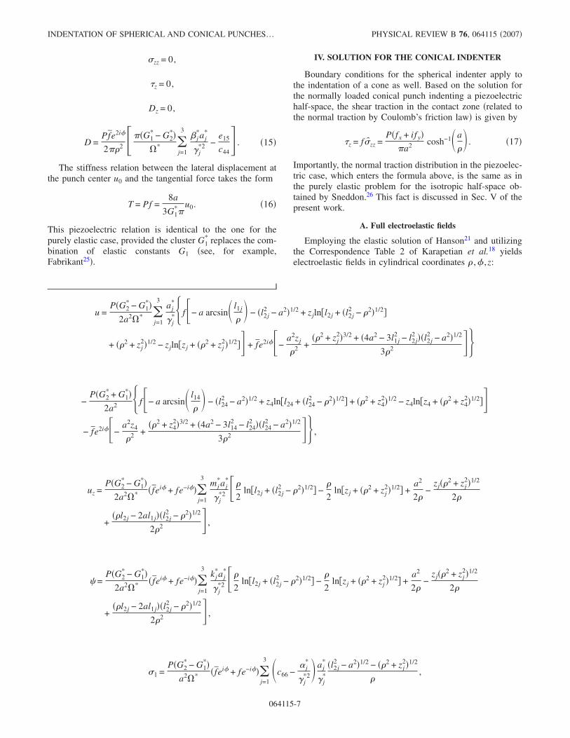
FIG. 5. �Color online� Two-dimensional spatial distribution of the x component of tangential displacement, ux �a�, �b�; x component ofshear stress, �xz �c�, �d�; and tangential x component of electric displacement, Dx �e�, �f�, for conical indenter geometry for BaTiO3 �a�, �c�,�e� and LiNbO3 �b�, �d�, �f�. Indentation parameters are indentation force P=1.54 �N; contact radius a=3 nm; coefficient of friction, f=0.3; and coordinate �=0.
MAKAGON et al. PHYSICAL REVIEW B 76, 064115 �2007�
064115-8
The radius a of the contact zone is obtained from thestiffness relation �22�, which relates the penetration depthand applied force.
Selected electroelastic fields for the conical indenter forBaTiO3 and LiNbO3 are shown in Fig. 5. Similar to the caseof the spherical indenter, the tangential displacement uxreaches maximum directly under the center of the indenterand decreases with increasing x and z coordinates. The shearstress �zx is also maximal on the surface under the center ofthe indenter and decreases with increasing distance alongboth axes. In contrast to the displacement field, lines of equalshear stress attain maximum distance from the origin at apoint neither on the x nor on the z axes, but rather some-where in between. The electric displacement field Dx is gen-erally similar to the one for the spherical indenter, with onemajor difference: the field reaches a maximum on the surfacefor both BaTiO3 and LiNbO3 �the maximum electric dis-placement for BaTiO3 under a spherical indenter is reachedat some depth below the material surface�.
This is explained by the fact that, close to the center of thepunch, for the conical indenter, the fields are controlledmostly by the geometric factors �rather than by the materialones�, in contrast to the spherical indenter. This produces asingularity at the center of the conical punch. This behavioris depicted in Fig. 5.
These observations are again clarified by the structure ofthe expression for the electric displacement along the z axisat the center of the indenter � =0�:
�19�
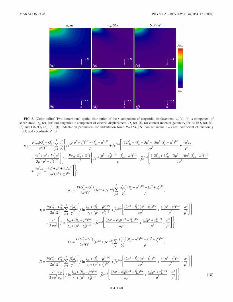
Figure 6 shows that, for both materials, the term B is thedominant one, going to negative infinity with decreasing zfaster than the A term goes to positive infinity. Both A and Bterms contain the logarithmic singularity, but the A -term has
the lessening material property clusterc44
e15 j=1
3 � j*aj
*
j*2 . Thus, the
dominance of the B term, due to the conical geometry of thepunch, requires the maximal value of the sum to be at thesurface �z=0�.
B. Electroelastic fields at the boundary of the half-space
At the boundary of the half-space �z=0�,the solution takesthe following form �Eq. �9� is utilized�.
�A� At �a �l1j = ; l2j =a�, we have
u =P
a2�G1*f�a�
2− � + G2
* f̄e2i�
3� ,
uz =�G2
* − G1*�P
4�*a2 � ln�a − �a2 − 2�1/2
� +
a2 − a�a2 − 2�1/2
�
�� f̄ei� + fe−i��j=1
3mj
*aj*
j*2 ,
� =�G2
* − G1*�P
4�*a2 � ln�a − �a2 − 2�1/2
� +
a2 − a�a2 − 2�1/2
�
�� f̄ei� + fe−i��j=1
3kj
*aj*
j*2 ,
�1 =�G1
* − G2*�P
�*a2 � f̄ei� + fe−i��j=1
3 �c66 −� j
*
j*2� aj
*
j* ,
�2 = −2c66P
a2 �G1*fei� + G2
* f̄e3i�
3� ,
�zz = 0,
�z = −Pf
�a2 cosh−1�a
� ,
Dz = 0,
FIG. 6. �Color online� Behavior of terms A and B entering Eq. �19� and their sum for BaTiO3 �a� and LiNbO3 �b�.
INDENTATION OF SPHERICAL AND CONICAL PUNCHES… PHYSICAL REVIEW B 76, 064115 �2007�
064115-9
D =P
2�a2��G2* − G1
*���*
j=1
3� j
*aj*
j*2 −
e15
c44� f ln
a + �a2 − 2�1/2
+ � �G2* − G1
*���*
j=1
3� j
*aj*
j*2 +
e15
c44� f̄e2i�a�a2 − 2�1/2 − a2
2 .
�20�
�B� At �a �l1j =a ; l2j = �, we have
u =P
a2G1*f�a arcsin�a
� + � 2 − a2�1/2 − �
+ G2* f̄e2i�� 3 − � 2 − a2�3/2
3 2 � ,
uz =�G2
* − G1*�P
4�* � f̄ei� + fe−i��
j=1
3mj
*aj*
j*2 ,
� =�G2
* − G1*�P
4�* � f̄ei� + fe−i��
j=1
3kj
*aj*
j*2 ,
�1 =�G2
* − G1*�P
�*a2 �� 2 − a2�1/2 − �� f̄ei� + fe−i��
�j=1
3 �c66 −� j
*
j*2� aj
*
j* ,
�2 =2c66P
a2 G1*fei�� � 2 − a2�1/2 −
�
+ G2* f̄e3i�
3� 3 − � 2 − 4a2�� 2 − a2�1/2
3 3 � ,
�zz = 0,
�z = 0,
Dz = 0,
D =Pf̄e2i�
2� 2 ���G1* − G2
*��*
j=1
3� j
*aj*
j*2 −
e15
c44� . �21�
The stiffness relation for the conical indenter takes the fol-lowing form:
T = Pf =2a
G1*�
u0. �22�
As in the case of the spherical indenter, the stiffness relationis similar to the one for the purely elastic case, with G1
*
replacing the combination of elastic constants G1.
V. DISCUSSION OF THE SOLUTIONS
As noted in Sec. II, the piezoelectric fields derived aboveare approximate for the following reasons.
�i� Stress distributions in the contact zone, for both spheri-cal and conical indenters, are actually different from that forthe normal frictionless indentation problem alone. Indeed,the normal load required to maintain constant penetrationdepth during frictional lateral motion is larger than the loadrequired to maintain the same depth in the frictionless nor-mal loading problem.
�ii� The frictional lateral motion actually produces a non-axisymmetric stress field in the contact zone, while the nor-mal indentation solution observed axial symmetry. Theasymmetry is a result of the leading edge of the punch hav-ing greater contact area than the trailing edge, to maintainequilibrium.
�iii� The normal displacement on the surface under thepunch, uz, in Eqs. �14� and �20�, is nonzero, even thoughonly lateral displacements should be present �as a result ofdecoupling�. The solution becomes exact when the normaldisplacement on the surface is zero. This occurs when the
piezoelectric cluster j=13 mj
*aj*
j*2 entering uz is zero.
�iv� A zero charge distribution was prescribed in the con-tact region, but a nonzero electric potential � appears in Eqs.�14� and �20�. The solution becomes exact when the piezo-electric cluster entering the expression for the electric poten-
tial, j=13 kj
*aj*
j*2 , is zero.
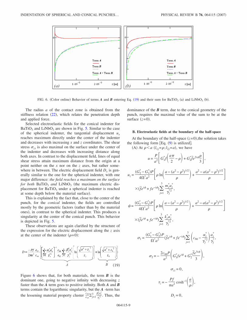
FIG. 7. �Color online� Lateral displacement ux and normal displacement uz on the surface �z=0� in the contact region for spherical �a� andconical �b� indenters.
MAKAGON et al. PHYSICAL REVIEW B 76, 064115 �2007�
064115-10
To evaluate the quality of the approximations involved inthe solution for the lateral problem, we compare the valuesof the normal and lateral displacements, Fig. 7. It is seen thatthe normal displacement is an order of magnitude smallerthan the lateral one. This indicates that the constructed solu-tion has satisfactory accuracy—on the order of 10%.
An important observation is that the shear traction underthe punch on the surface obtained in Secs. III B and IV B isidentical to the shear traction for a purely elastic isotropicmaterial, as given by Harding and Sneddon24 and Sneddon26
and for the transversely isotropic material as well �Green andZerna27�. Therefore, as far as the contact problems discussedhere are concerned, the difference between the purely elasticand the piezoelectric materials is observed only at nonzerodepth, provided that the punch is electrically grounded �elec-trical boundary conditions are set to null�.
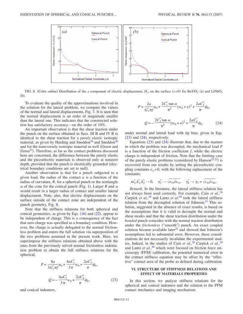
Another observation is that for a punch subjected to agiven load, the radius of the contact a is a function of theradius of curvature, R, for a spherical punch or the semiangle� of the cone for the conical punch �Fig. 1�. Larger R and �would result in a larger radius of contact and smaller lateraldisplacement. Note, also, that electric displacements on thesurface outside of the contact zone are independent of thepunch geometry, Fig. 8.
Note that the stiffness relations for both spherical andconical geometries, as given by Eqs. �16� and �22�, appear tobe independent of charge. This is a consequence of the factthat zero charge was specified as a boundary condition. How-ever, the charge is actually delegated to the normal friction-less problem and enters the full solution via superposition ofthe two problems assumed in the present work. Here, wesuperimpose the stiffness relations obtained above with theones from the previously solved normal frictionless indenta-tion problem to obtain the full stiffness relations for thespherical,
P =8a
3G1*�f
u0 +4aC1
*
3�w0 +
2aC3*
��0,
Q = −4aC3
*
3�w0 +
2aC4*
��0, �23�
and conical indenters,
P =2a
G1*�f
u0 +2C1
* tan �
�2 �w0 + ��2 +2aC3
*
��0,
Q = −2C3
* tan �
�2 �w0 + ��2 +2aC4
*
��0, �24�
under normal and lateral load with tip bias, given in Eqs.�23� and �24�, respectively.
Equations �23� and �24� illustrate that, due to the mannerin which the problem was decoupled, the mechanical load Pis a function of the friction coefficient f , while the electriccharge is independent of friction. Note that the limiting caseof the purely elastic problems �considered by Hanson21,22� isrecovered from our results by setting the piezoelectric cou-pling constants eij =0, with the following replacement of theconstants:
m3*,k1
*,k2* → 0, 3
* → ��33/�11, 4* → 3 = �c44/c66.
Remark. In the literature, the lateral stiffness relation hasnot always been used correctly. For example, Cain et al.,28
Carpick et al.,29 and Lantz et al.30 took the lateral stiffnessrelation from the decoupled solution of Johnson.31 This so-lution, suggested in the absence of exact results, is based onthe assumptions that it is valid to decouple the normal andshear modes and that the shear traction distribution under thebonded punch coincides with the normal traction distributionunder the frictionless �“smooth”� punch. An exact coupledsolution became available later25 and showed that Johnson’sassumptions led to substantial error. However, these consid-erations do not necessarily invalidate the experimental stud-ies. Indeed, in the studies of Cain et al.,28 Carpick et al.,29
and Lantz et al.,30 which were focused on friction force mi-croscopy �FFM� calibration, the potential numerical error inthe contact stiffness equation may be offset by the “effec-tive” contact area of the probe as defined during calibration.
VI. STRUCTURE OF STIFFNESS RELATIONS ANDEFFECT OF MATERIALS PROPERTIES
In this section, we analyze stiffness relations for thespherical and conical indenters and the relation to the PFMcontact mechanics and imaging mechanism.
FIG. 8. �Color online� Distribution of the x component of electric displacement, Dx, on the surface �z=0� for BaTiO3 �a� and LiNbO3
�b�.
INDENTATION OF SPHERICAL AND CONICAL PUNCHES… PHYSICAL REVIEW B 76, 064115 �2007�
064115-11
A. Discussion of the stiffness relations
We now analyze the stiffness relations that relate the ap-plied lateral force T and the lateral displacement at the punchcenter u0 �as derived in Secs. III and IV� and have the form,for the spherical and the conical indenters,
T =8a
3G1*�
u0 �spherical� ,
T =2a
G1*�
u0 �conical� . �25�
We consider the dependence of the piezoelectric constantcluster G1
* entering these relations, as well as the associatedcluster G2
*, given by Eq. �7�, on their ten constituent indepen-dent piezoelectric constants: five elastic stiffnesses cij, threeelectroelastic coupling constants eij, and two dielectric per-meabilities �ij. In order to identify the relative contributionof each piezoelectric constant to a cluster Gk
*, a sensitivityfunction of that cluster is defined as the logarithmic deriva-tive of Gk
* with respect to a selected piezoelectric constant f ijas follows: Sk�f ij�=��ln�Gk
*�� /��ln�f ij��. Numerically, thesensitivity function is calculated as
Sk�f ij� =�Gk
*� f ij=1.01f ij0 − �Gk
*� f ij=0.99f ij0
0.02�Gk*� f ij=f ij
0, �26�
where f ij is a selected piezoelectric constant and f ij0 is a ref-
erence value for that constant. A positive value of Sk�f ij�implies that a higher constant value favors a cluster increase,while for negative values of Sk�f ij� the cluster decreases withthe constant. Sk�f ij��0 indicates that the cluster is indepen-dent of that property. The sensitivity of clusters Gk
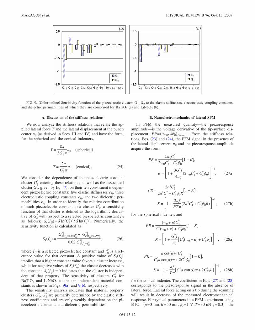
* forBaTiO3 and LiNbO3 to the ten independent material con-stants is shown in Figs. 9�a� and 9�b�, respectively.
The sensitivity analysis indicates that material propertyclusters G1
*, G2* are primarily determined by the elastic stiff-
ness coefficients and are only weakly dependent on the pi-ezoelectric constants and dielectric permeabilities.
B. Nanoelectromechanics of lateral SPM
In PFM the measured quantity—the piezoresponseamplitude—is the voltage derivative of the tip-surface dis-placement, PR= ��w0 /��0�P=const.. From the stiffness rela-tions, Eqs. �23� and �24�, the PFM signal in the presence ofthe lateral displacement u0 and the piezoresponse amplitudeacquire the form
PR =2w0C3
*
2w0C1* + C3
*�0�1 − K�,
K = �1 +3G1
*f
4u0�2w0C1
* + C3*�0��−1
, �27a�
PR =2a2C3
*
2a2C1* + C3
*�0R�1 − K�,
K = �1 +2af
RT��2a2C1
* + C3*�0R��−1
, �27b�
for the spherical indenter, and
PR =�w0 + ��C3
*
C1*�w0 + �� + C3
*�0�1 − K�,
K = �1 +G1
*f
u0�C1
*�w0 + �� + C3*�0��−1
, �28a�
PR =a cot����C3
*
C1*a cot���� + 2C3
*�0�1 − K�,
K = �1 +af
T��C1
*a cot���� + 2C3*�0��−1
, �28b�
for the conical indenter. The coefficient in Eqs. �27� and �28�corresponds to the piezoresponse signal in the absence oflateral force. Lateral force acting on a tip during the scanningwill result in decrease of the measured electromechanicalresponse. For typical parameters in a PFM experiment usingBTO �a=3 nm,R=50 nm,�0=1 V,T=30 nN, f =0.3� the
FIG. 9. �Color online� Sensitivity function of the piezoelectric clusters G1*, G2
* to the elastic stiffnesses, electroelastic coupling constants,and dielectric permiabilities of which they are comprised for BaTiO3 �a� and LiNbO3 �b�.
MAKAGON et al. PHYSICAL REVIEW B 76, 064115 �2007�
064115-12
magnitude of K for a spherical indenter is 0.18. This indi-cates the relative importance of the lateral displacement con-tribution to the piezorespose amplitude.
A similar analysis for the quantity measured in atomicforce acoustic microscopy, k1= ��w0 /�P��0=const—the inversevertical spring constant of the tip-surface junction—yields
k1 =��w0
�R�2w0C1* + C3
*�0��1 − K�,
K = �1 +3G1
*f
4u0�2w0C1
* + C3*�0��−1
, �29a�
k1 =�a
2a2C1* + RC3
*�0�1 − K�,
K = �1 +2af
RT��2a2C1
* + C3*�0R��−1
, �29b�
for the spherical indenter, and
k1 =�w0 + ���
2aC1*�w0 + �� + 2aC3
*�0�1 − K�,
K = �1 +G1
*f
u0�C1
*�w0 + �� + C3*�0��−1
, �30a�
k1 =cot����2
2C1*a cot���� + 4C3
*�0�1 − K�,
K = �1 +af
T��C1
*a cot���� + 2C3*�0��−1
, �30b�
for the conical indenter.Finally, to complement PFM, AFAM can be used to mea-
sure the voltage-dependent lateral contact stiffness of tip sur-face junction. From Eq. �25�, the lateral contact stiffness de-pends only on the effective contact area and does notexplicitly depend on tip bias. However, the contact area isbias dependent from Eq. �23� and �24�, as analyzed in detailin Kalinin et al.19 Hence, the lateral contact stiffness can beused as a measure of bias-dependent contact area in PFM,suggesting a route for independent measurement of the latter.
VII. CONCLUSIONS
The piezoelectric indentation of punches of spherical andconical shapes into a piezoelectric half-space accompaniedby frictional sliding is analyzed. The obtained solutions, de-rived in elementary functions, give the full electroelasticfields in explicit form, as well as exact stiffness relations.
These results form the basis for quantification of SPM tech-niques for ferroelectric and piezoelectric materials. The prob-lem is solved under the approximation whereby the normaland the tangential parts of the problem are decoupled. Esti-mates show that this assumption is satisfactory, with errorson the order of 10%. The present work focuses on the tan-gential part of the problem; the normal one has been solvedpreviously.
The main results relevant for SPM applications are asfollows.
�i� The lateral contact stiffness does not explicitly dependon indenter bias and is determined only by the radius ofcontact.
�ii� The effective piezoelectric shear modulus is primarilydetermined by the elastic material constants, while piezo-electric and dielectric constants provide only minor contribu-tions.
�iii� The presence of lateral displacement results in a de-crease of indentation depth, thus reducing piezoresponse at agiven indentation force.
The present work suggests important applications for in-terpretation of various scanning probe microscopy tech-niques of ferroelectric surfaces. First, measurements of thelateral contact stiffness using lateral AFAM or FFM can pro-vide an independent method to establish the voltage-dependent contact area for subsequent use in PFM �i.e., tocalibrate the contact area between the probe and the surface�.Second, the friction force is expected to be only weakly de-pendent on piezoelectric and dielectric material properties atzero tip bias. Hence, the observed friction contrast on ferro-electric domains is likely attributed to variations inpolarization-dependent chemical properties, rather than in-trinsic polarization response. At the same time, application offinite voltage bias will result in strong changes in effectivecontact area, and hence the friction force will be domainpolarity dependent. For positive domains, the contact areadecreases for positive tip biases, with associated decrease offriction force, and increases for negative bias. The situationis reversed for negative domains. Hence, friction force mea-surements under dc tip bias can provide direct imaging ofdomain polarity. Finally, we mention that the solution pre-sented here assumes that during experimentation the indentertip velocities are constant or exhibit relatively low accelera-tion.
ACKNOWLEDGMENT
This research has been supported by the National ScienceFoundation through a grant to Tufts University �No. CMS-0509936�.
*Corresponding author. [email protected]†Corresponding author. [email protected] U. Rabe, V. Sherer, S. Hirsekorn, and W. Arnold, J. Vac. Sci.
Technol. B 15, 1506 �1997�.
2 N. A. Burnham, A. J. Kulik, G. Gremaud, P.-J. Gallo, and F.Oulevey, J. Vac. Sci. Technol. B 14, 794 �1996�.
3 P. Maivald, H. J. Butt, S. A. C. Gould, C. B. Prater, B. Drake, J.A. Gurley, V. B. Elings, and P. K. Hansma, Nanotechnology 2,
INDENTATION OF SPHERICAL AND CONICAL PUNCHES… PHYSICAL REVIEW B 76, 064115 �2007�
064115-13
103 �1991�.4 S. A. Syed Asif, K. J. Wahl, R. J. Colton, and O. L. Warren, J.
Appl. Phys. 90, 1192 �2001�.5 K. Yamanaka, H. Ogiso, and O. Kolosov, Appl. Phys. Lett. 64,
178 �1994�.6 Applied Scanning Probe Methods, edited by B. Bhushan, H.
Fuchs, and S. Hosaka �Springer-Verlag, Berlin, 2004�.7 Nanoscale Characterization of Ferroelectric Materials, edited by
M. Alexe, and A. Gruverman �Springer-Verlag, Berlin, 2004�.8 C. Halperin, S. Mutchnik, A. Agronin, M. Molotskii, P. Urenski,
M. Salai, and G. Rosenman, Nano Lett. 4, 1253 �2004�.9 J. Shin, B. J. Rodriguez, A. P. Baddorf, T. Thundat, E. Karapetian,
M. Kachanov, A. Gruverman, and S. V. Kalinin, J. Vac. Sci.Technol. B 23, 2102 �2005�.
10 S. V. Kalinin, B. J. Rodriguez, S. Jesse, T. Thundat, and A. Gru-verman, Appl. Phys. Lett. 87, 053901 �2005�.
11 L. M. Eng, M. Friedrich, J. Fousek, and P. Gunter, J. Vac. Sci.Technol. B 14, 1191 �1996�.
12 H. Bluhm, U. D. Schwarz, and R. Wiesendanger, Phys. Rev. B57, 161 �1998�.
13 A. Correia, J. Massanell, N. Garcia, A. P. Levanyuk, A. Zlatkin,and J. Przeslawski, Appl. Phys. Lett. 68, 2796 �1996�.
14 W. Q. Chen, Arch. Appl. Mech. 69, 455 �1999�.15 W. Q. Chen and H. Ding, Acta Mech. Sol. Sin. 12, 114 �1999�.16 A. E. Giannakopoulos and S. Suresh, Adv. Mater. �Weinheim,
Ger.� 47, 2153 �1999�.
17 A. E. Giannakopoulos, J. Appl. Mech. 67, 409 �2000�.18 E. Karapetian, M. Kachanov, and I. Sevostianov, Arch. Appl.
Mech. 72, 564 �2002�.19 S. V. Kalinin, E. Karapetian, and M. Kachanov, Phys. Rev. B 70,
184101 �2004�.20 E. Karapetian, M. Kachanov, and S. V. Kalinin, Philos. Mag. B
85, 1017 �2005�.21 M. Hanson, J. Appl. Mech. 59, S123 �1992�.22 M. Hanson, ASME J. Tribol. 114, 606 �1992�.23 E. Karapetian, I. Sevostianov, and M. Kachanov, Philos. Mag. B
80, 331 �2000�.24 W. Harding and I. N. Sneddon, Proc. Cambridge Philos. Soc. 41,
16 �1945�.25 V. I. Fabrikant, Applications of Potential Theory in Mechanics
�Kluwer, Dordrecht, 1989�.26 I. N. Sneddon, Proc. Cambridge Philos. Soc. 44, 492 �1948�.27 A. E. Green and W. Zerna, Theoretical Elasticity �Oxford Univer-
sity Press, London, 1968�.28 R. G. Cain, S. Briggs, and N. W. Page, J. Colloid Interface Sci.
227, 55 �2000�.29 R. W. Carpick, D. F. Ogletree, and M. Salmeron, Appl. Phys.
Lett. 70, 1548 �1997�.30 M. A. Lantz, A. J. O’shea, A. C. F. Hoole, and M. E. Welland,
Appl. Phys. Lett. 70, 970 �1997�.31 K. L. Johnson, Contact Mechanics �Cambridge University Press,
Cambridge, England, 1969�.
MAKAGON et al. PHYSICAL REVIEW B 76, 064115 �2007�
064115-14