indesse industry
TRANSCRIPT
EN INSTALLATION AND OPERATION
P01-0302-0515-01
8595102264341
INDESSE IndustryVCIN AC/EC
v3

EN INSTALLATION AND OPERATION ............................................................................................... 3
BEFORE YOU BEGIN ....................................................................................................... 4 UNPACKING ....................................................................................................................... 5 MAIN PARTS ....................................................................................................................... 6 SPARE PARTS ..................................................................................................................... 7 DIMENSIONS ..................................................................................................................... 8 TECHNICAL SPECIFICATIONS...................................................................................... 9 INSTALLATION ................................................................................................................... 10 FIRST USE ............................................................................................................................. 30 MAINTENANCE .................................................................................................................. 31 TROUBLESHOOTING ....................................................................................................... 32 PRODUCT DISPOSAL ...................................................................................................... 34 IN CONCLUSION ................................................................................................................ 35

EN INSTALLATION AND OPERATION
INDESSE IndustryVCIN

44
1. BEFORE YOU BEGIN
This manual contains important instructions for the proper installation of the INDESSE Industry air curtain. Before the installation of the air curtain, please read all these instructions and follow them! The manufac-turer reserves the right to make changes, including to the technical documentation without prior notice. Please save this manual for future use. Consider this manual as a part of the product.
This manual contains important instructions for the safe connecting of the air curtain. Before connecting the unit, please read all instructions below and follow them! The manufacturer reserves the right to make changes, including to the tech-nical documentation without prior notice. Please save this manual for future use. Consider this manual to be part of the product.
EC DECLARATION OF CONFORMITY
The product has been designed, manufactured, placed on the market, complies with all applicable regulations and is in compliance with the requirements of the directives of the European Parliament and the Council, including amendments to the proposal, under which it was classified. Under normal conditions and in the instruction manual for the intended use and installation, it is safe. The harmonized European standards referred to in the relevant EC declaration of conformity have been applied in the assessment.
For the current and full version of the EC Declaration of Conformity, please see www.2vv.cz or the enclosed CD. (when at-tached to the packaging).
Symbols are used in the text for better orientation in the manual. The following table shows their illustrations and meanings:
Symbol Meaning
ATTENTION! Warning or caution
IMPORTANT NOTICE! Important information
YOU WILL NEED Practical tips and information
Technical information More technical information
Link to another part of the manual

5
2. UNPACKING
2.1 CHECK DELIVERY
• After delivery, immediately check whether the packaged product is damaged. Summon the carrier in case of damage to the packaging. If a claim is not lodged in a timely manner, it is not possible to en-force potential claims in the future.
• Check if your ordered product type agrees. In case of disagreement do not unpack the air curtain and report the defect to the supplier immediately.
• After unpacking, check that the air curtain and all components are in order. If in doubt, contact the supplier.
• Never install a damaged air curtain.• If you do not unpack the air curtain immediately
after delivery, it must be stored indoors in a dry environment with an ambient temperature from + 0 ° C to + 40 ° C.
2.2 UNPACK THE AIR CURTAIN
• If the air curtain was transported at temperatures below 0 ° C, it is necessary to leave it in the operat-ing environment for at least 2 hours without turn-ing on after unpacking, for temperature compensa-tion inside the air curtain to occur.
0
40
INDESSE
All packaging materi-als are environmentally friendly and can be reused or recycled. Contribute to protection of the environ-ment actively and ensure the proper disposal and recycling of packaging materials.
1x Air curtain
Packaged accessories:2 x Connecting part
1x Manual

66
Box for the connection of fans
Water / electric exchanger (within air curtain)
Fans
Exhaust grille (Straw system)
Box for the connection of the electric heater (can be exchanged for contactor module - accessories)
Connecting straps (2 pcs, they are part of the air curtain)
3. MAIN PARTS

7
4. SPARE PARTS
Nr. DescriptionVCIN2A150 VCIN2A200 VCIN2A250
codepc/air
curtaincode
pc/air curtain
codepc/air
curtain
Motor AC ND-VEN-AC-AX-YWF4E-450B-V 3 ND-VEN-AC-AX-YWF4E-450B-V 4 ND-VEN-AC-AX-YWF4E-450B-V 5
Motor EC ND-VEN-EC-AX-EC102-A450 3 ND-VEN-EC-AX-EC102-A450 4 ND-VEN-EC-AX-EC102-A450 5
Electro-installation box
ND-VCIN1-KRAB-VENT 1 ND-VCIN1-KRAB-VENT 1 ND-VCIN1-KRAB-VENT 1
Waterexchanger
ND-VCIN1-VV-15 1 ND-VCIN1-VV-20 1 ND-VCIN1-VV-25 1
Electric exchanger
ND-VCIN1-EL-VYM 3 ND-VCIN1-EL-VYM 4 ND-VCIN1-EL-VYM 5
Straw system including a frame
ND-VCIN1-VOST 3 ND-VCIN1-VOST 4 ND-VCIN1-VOST 5
1
2
3
4
1
1
1
2
4
4
4
3

88
5. DIMENSIONS
Con
tact
or b
ox*
* - Accessories
VCIN A [mm] B [mm]150 1650 320200 2200 870250 2750 870
VCIN A [mm] B [mm]150 1650 1526200 2200 2076250 2750 2626
VCIN A [mm]150 1650200 2200250 2750
VCIN A [mm]150 1650200 2200250 2750
252
550
550
275
521
210
634
521
117 405
A
551
B
550
75
284
1,5 m 2 m 2,5 m
A 1650 mm 2200 mm 2750 mm
B 320 mm 870 mm 870 mm
ELEKTRICKÁ VERZE
210252
521
117 405
521
275
A
551
550
550
550
75
1,5 m 2 m 2,5 m
A 1650 mm 2200 mm 2750 mm
STUDENÁ VERZE
G1"
275
59
6262 59
B A
551
550
550
550
75
117 405
244521
610
252210
521
246
1,5 m 2 m 2,5 m
A 1650 mm 2200 mm 2750 mm
B 1525,6 mm 2075,5 mm 2625,5 mm
VODNÍ VERZE
PROTIMRAZOVÁOCHRANA
G1"
85
59
40
551
62
59
62
275
A
550
75
550
550
117 405
521
610
252210
521
1,5 m 2 m 2,5 m
A 1650 mm 2200 mm 2750 mm
VODNÍ VERZE S PROTIMRAZOVOU OCHRANOU
Ant
ifree
ze p
rote
ctio
n252
550
550
275
521
210
634
521
117 405
A
551
B
550
7528
4
1,5 m 2 m 2,5 m
A 1650 mm 2200 mm 2750 mm
B 320 mm 870 mm 870 mm
ELEKTRICKÁ VERZE
252
550
550
275
521
210
634
521
117 405
A
551
B
550
75
284
1,5 m 2 m 2,5 m
A 1650 mm 2200 mm 2750 mm
B 320 mm 870 mm 870 mm
ELEKTRICKÁ VERZE
210252
521
117 405
521
275
A
551
550
550
550
75
1,5 m 2 m 2,5 m
A 1650 mm 2200 mm 2750 mm
STUDENÁ VERZE
210252
521
117 405
521
275
A
551
550
550
550
75
1,5 m 2 m 2,5 m
A 1650 mm 2200 mm 2750 mm
STUDENÁ VERZE
PROTIMRAZOVÁOCHRANA
G1"
85
59
40
551
62
59
62
275
A
550
7555
055
0
117 405
521
610
252210
521
1,5 m 2 m 2,5 m
A 1650 mm 2200 mm 2750 mm
VODNÍ VERZE S PROTIMRAZOVOU OCHRANOU
G1"
275
59
6262 59
B A
551
550
550
550
75
117 405
244521
610
252210
521
246
1,5 m 2 m 2,5 m
A 1650 mm 2200 mm 2750 mm
B 1525,6 mm 2075,5 mm 2625,5 mm
VODNÍ VERZE
PROTIMRAZOVÁOCHRANA
G1"
85
59
40
551
6259
62
275
A
550
75
550
550
117 405
521
610
252210
521
1,5 m 2 m 2,5 m
A 1650 mm 2200 mm 2750 mm
VODNÍ VERZE S PROTIMRAZOVOU OCHRANOU
G1"
275
59
6262 59
B A
551
550
550
550
75
117 405
244521
610
252210
521
246
1,5 m 2 m 2,5 m
A 1650 mm 2200 mm 2750 mm
B 1525,6 mm 2075,5 mm 2625,5 mm
VODNÍ VERZE
VCIN...-E1..
VCIN...-V2.. VCIN...-P2..
VCIN...-S0..

9
Type of air curtain
Postflow * Air output
Noise [dB(A)]** Heater output *** Heater
power supplyFans power
supply Weight
[m] [m³/h] 3m 5m [kW] [V/A] [V/A] [kg]VCIN...150-S0AC
7,5
11550 67,5 63,0 - - 230/3,9 51
VCIN...150-V2AC10300 67,5 63,1 91,3*** - 230/3,9 60
VCIN...150-P2AC
VCIN...150-E1AC 11550 67,5 63,0 24,3 400/35,2 230/3,9 55
VCIN...200-S0AC
8,0
15100 69,3 64,9 - - 230/5,1 69
VCIN...200-V2AC13700 68,4 64,0 123*** - 230/5,4 78
VCIN...200-P2AC
VCIN...200-E1AC 15100 69,3 64,9 32,4 400/47,0 230/5,1 74
VCIN...250-S0AC
7,5
18500 71,1 66,7 - - 230/6,5 83
VCIN...250-V2AC17000 70,0 65,5 154*** - 230/6,7 98
VCIN...250-P2AC
VCIN...250-E1AC 18500 71,1 66,7 40,5 400/58,6 230/6,5 89
Type of air curtain
Postflow * Air output
Noise [dB(A)]** Heater output *** Heater
power supplyFans power
supply Weight
[m] [m³/h] 3m 5m [kW] [V/A] [V/A] [kg]VCIN...150-S0EC
7,5
11400 # # - - 230/3,87 51
VCIN...150-V2EC10500 # # # - 230/3,95 60
VCIN...150-P2EC
VCIN...150-E1EC 11400 # # # 400/35,2 230/3,87 55
VCIN...200-S0EC
8,0
15200 # # - - 230/5,16 69
VCIN...200-V2EC13700 # # # - 230/5,27 78
VCIN...200-P2EC
VCIN...200-E1EC 15200 # # # 400/47,0 230/5,16 74
VCIN...250-S0EC
7,5
19000 # # - - 230/6,45 83
VCIN...250-V2EC17500 # # # - 230/6,85 98
VCIN...250-P2EC
VCIN...250-E1EC 19000 # # # 400/58,6 230/6,45 89
* The distance at which the medium speed of air flow drops to 3 m / s. (under optimal conditions and max. output of device, measured according to ISO 27327-1))** Acoustic pressure at a distance of 3 m or 5 m from the air curtain and parameter Q = 2.*** With the temperature water gradient 110/80 ° C and the intake air temperature + 15 ° C.
6. TECHNICAL SPECIFICATIONS
# Other specifications can be found in the technical sheet of the product
EC
AC

1010
POSSIBLE WAYS OF INSTALLATION - VERTICAL INSTALLATION
7. INSTALLATIONYour partner in ventilation...
Produced in EU
125
CONTROL BEDIENUNG
Die Luftschleier werden ohne integrierte Regulation geliefert. Für ihre Regulierung wird folgendes Zubehör empfohlen.
INDESSE Industry
The company reserves the right of change without previous announcement. ©2VV, spol. s r.o.
AIR CURTAINS LUFTSCHLEIER
min.300mm
Anchoring structure (building delivery)Anchoring holder
Inle
tA
nsa
ugen
1 module VCP-03-055
Ankerkonstruktion (Lieferung der Baustelle)Ankerhalter
1 Modul VCP-03-055
Vertical installation, side viewVertikale Installatin, Seitensicht
VCP-DH-01 horizontal holderHorizontalhalter
Horizontal installation, side viewHorizontale Installation, Seitensicht
Door openingTüröffung
Min
. 00 m
m3
Min. 00 mm3
The air curtains are shipped without integrated control system. The following accessories are recommended to allow their regulation.
INDESSE Industry
INDESSE Industry VCP-03
Anchoring holder Ankerhalter
VCP-DK-01
Your partner in ventilation...
Produced in EU
125
CONTROL BEDIENUNG
Die Luftschleier werden ohne integrierte Regulation geliefert. Für ihre Regulierung wird folgendes Zubehör empfohlen.
INDESSE Industry
The company reserves the right of change without previous announcement. ©2VV, spol. s r.o.
AIR CURTAINS LUFTSCHLEIER
min.300mm
Anchoring structure (building delivery)Anchoring holder
Inle
tA
nsa
ug
en
1 module VCP-03-055
Ankerkonstruktion (Lieferung der Baustelle)Ankerhalter
1 Modul VCP-03-055
Vertical installation, side viewVertikale Installatin, Seitensicht
VCP-DH-01 horizontal holderHorizontalhalter
Horizontal installation, side viewHorizontale Installation, Seitensicht
Door openingTüröffung
Min
. 0
0 m
m3
Min. 00 mm3
The air curtains are shipped without integrated control system. The following accessories are recommended to allow their regulation.
INDESSE Industry
INDESSE Industry VCP-03
Anchoring holder Ankerhalter
VCP-DK-01
Min. 300mm Min. 300mmVCIN2-KOT-V-STENA Wall Bracket
Vertical installation, side view, with a mobile base and a wall bracket
Vertical installation, side view, firmly attached to the floor
Installation on one side Installation from both sides to achieve a better screening effect
Door Door
VCIN2-KOT-V-PODSTMobile base
VCIN2-KOT-V-ZEMStable bracket

11
POSSIBLE WAYS OF INSTALLATION - HORIZONTAL INSTALLATION
Horizontal installation on the ceiling
Horizontal installation on the wall
7. INSTALLATION
Movable ceiling bracketVCIN2-KOT-H-STROP
THREADED RODS ARE NOT SUPPLIED, THEY MUST BE ENSURED.
THREADED RODS ARE NOT SUPPLIED, THEY MUST BE ENSURED.
Movable wall bracketVCIN2-KOT-H-STENA

1212
Installation dimensions - horizontal installation
• The air curtain must be aligned in the horizontal level!• •It must be operated indoors, in covered and dry areas with ambient temperatures from + 5 ° C to + 40 ° C and
a relative humidity of 80%.• The air curtain is not intended for the transport of air containing flammable or explosive mixtures, chemical
fumes, coarse dust, soot, grease, poisons, germs etc. e.g. car washes, fuel storage spaces, spaces for livestock breeding.
7. INSTALLATION
Your partner in ventilation...
Produced in EU
125
CONTROL BEDIENUNG
Die Luftschleier werden ohne integrierte Regulation geliefert. Für ihre Regulierung wird folgendes Zubehör empfohlen.
INDESSE Industry
The company reserves the right of change without previous announcement. ©2VV, spol. s r.o.
AIR CURTAINS LUFTSCHLEIER
min.300mm
Anchoring structure (building delivery)Anchoring holder
Inle
tA
nsa
ug
en
1 module VCP-03-055
Ankerkonstruktion (Lieferung der Baustelle)Ankerhalter
1 Modul VCP-03-055
Vertical installation, side viewVertikale Installatin, Seitensicht
VCP-DH-01 horizontal holderHorizontalhalter
Horizontal installation, side viewHorizontale Installation, Seitensicht
Door openingTüröffung
Min
. 00 m
m3
Min. 00 mm3
The air curtains are shipped without integrated control system. The following accessories are recommended to allow their regulation.
INDESSE Industry
INDESSE Industry VCP-03
Anchoring holder Ankerhalter
VCP-DK-01
VCIN2-KOT-H-ZAVESHinge on air curtain
VCIN2-KOT-H-STENAWall bracket
Door
Min. 300mm
2
2
1
1
1
VCIN2-KOT-H-STROPCeiling bracket
Your partner in ventilation...
Produced in EU
125
CONTROL BEDIENUNG
Die Luftschleier werden ohne integrierte Regulation geliefert. Für ihre Regulierung wird folgendes Zubehör empfohlen.
INDESSE Industry
The company reserves the right of change without previous announcement. ©2VV, spol. s r.o.
AIR CURTAINS LUFTSCHLEIER
min.300mm
Anchoring structure (building delivery)Anchoring holder
Inle
tA
nsa
ug
en
1 module VCP-03-055
Ankerkonstruktion (Lieferung der Baustelle)Ankerhalter
1 Modul VCP-03-055
Vertical installation, side viewVertikale Installatin, Seitensicht
VCP-DH-01 horizontal holderHorizontalhalter
Horizontal installation, side viewHorizontale Installation, Seitensicht
Door openingTüröffung
Min
. 00 m
m3
Min. 00 mm3
The air curtains are shipped without integrated control system. The following accessories are recommended to allow their regulation.
INDESSE Industry
INDESSE Industry VCP-03
Anchoring holder Ankerhalter
VCP-DK-01
Min. 300mm
Door
VCIN2-KOT-H-ZAVESHinge on air curtain
2
2
1
11
10° ~ 40°10° ~ 40°

13
Installation dimensions - vertical installation
• The air curtain must be aligned in the vertical level!• The bottom air curtain must stand on a flat, stable surface.• It must be operated indoors, in covered and dry areas with ambient temperatures from + 5 ° C to + 40 ° C and a relative
humidity of 80%.• The air curtain is not intended for transport of air containing flammable or explosive mixtures, chemical fumes, coarse
dust, soot, grease, poisons, germs etc.• For proper operation, it is recommended that the air curtain is rotated by exhaust out of 10 degrees.
Floor plan of vertical installation
7. INSTALLATION
min 300
min
100
1414
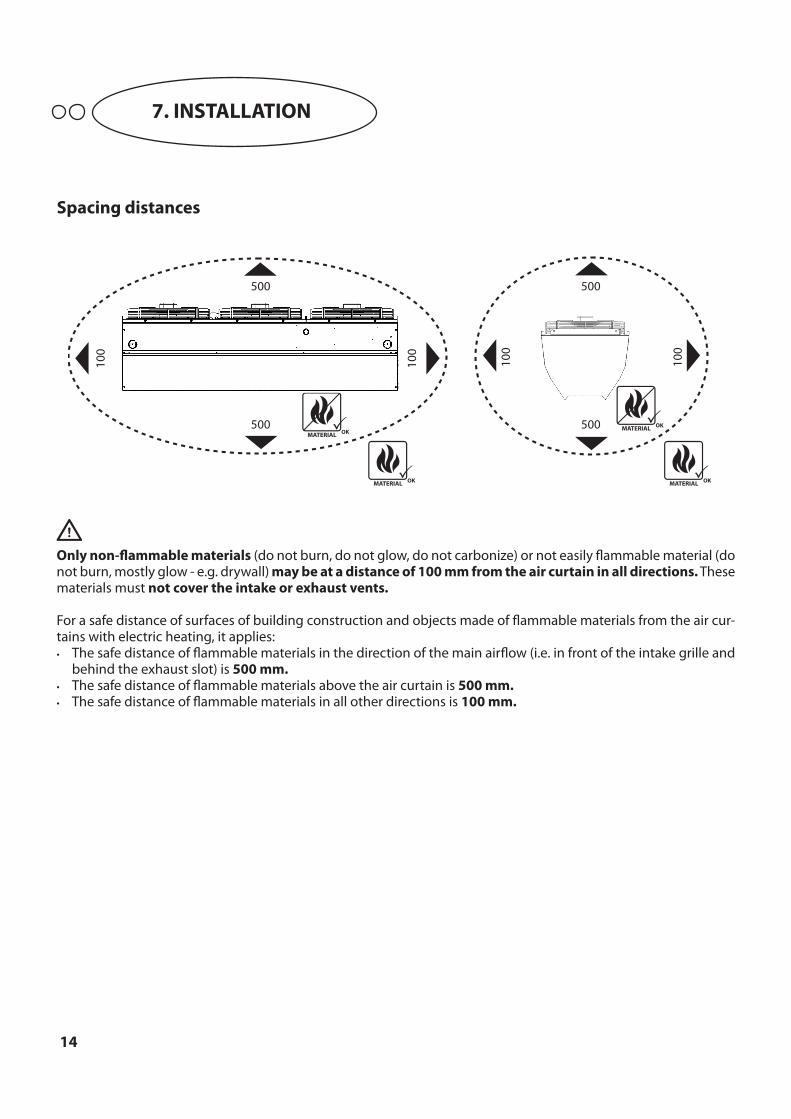
Spacing distances
Only non-flammable materials (do not burn, do not glow, do not carbonize) or not easily flammable material (do not burn, mostly glow - e.g. drywall) may be at a distance of 100 mm from the air curtain in all directions. These materials must not cover the intake or exhaust vents.
For a safe distance of surfaces of building construction and objects made of flammable materials from the air cur-tains with electric heating, it applies:• The safe distance of flammable materials in the direction of the main airflow (i.e. in front of the intake grille and
behind the exhaust slot) is 500 mm.• The safe distance of flammable materials above the air curtain is 500 mm.• The safe distance of flammable materials in all other directions is 100 mm.
7. INSTALLATION
MATERIAL OK MATERIAL OK
MATERIAL OK MATERIAL OK
500 500
500 50010
0
100
100
100

15
The modular assembly of air curtains
From the individual modules of INDESSE Industry air curtains we can create assemblies depending on the require-ments for the desired length, air power or heating capacity of the assembly. When installing and greater height of assembly it is necessary to take into account the weight that will affect the bottom air curtain. Individual modules are connected through connecting straps. Two pieces of straps are part of each INDESSE Industry air curtain.
Example: Vertical assembly 2x VCIN250 wall bracket - that can be used as a connecting link of 2 modules mobile base
Side anchoring:We recommend to install from a height greater than 4 meters.
The maximum height of the air curtains is limited to 6.5 m:If you require a greater height, you must create a supporting structure to avoid damage of the bottom bearing air curtain.
7. INSTALLATION
2
1
2
1
Connecting straps don’t have connecting bolts. It is necessary to ensure 4 pieces M5x10mm for each connecting straps to connect them.

1616
HORIZONTAL MOUNTING OF THE AIR CURTAIN
Measure the place of the horizontal installation and fasten the consoles Pension consoles are optional accessories and must be ordered.
Installation on the ceiling through VCIN2-KOT-H-STROP
Installation on the ceiling through VCIN2-KOT-H-STENA
7. INSTALLATION
Used material: Wall plug
Ceiling bracket (part of the set: VCIN2-KOT-H-STROP)
Screw
Used material:
Wall plug
Ceiling bracket (part of the set: VCIN2-KOT-H-STENA)
Screw
2 2
3 3
1 1
1
2
3
1
2
3
113,3
60205
320375
40
580
635
1010 50
40
5010
10 1040
10
50
804,7
1003,7
113,3
60205
320375
40
580
635
1010 50
40
5010
10 1040
10
50
804,7
1003,7
113,3
60205
320375
40
580
635
1010 50
40
5010
10 1040
10
50
804,7
1003,7
50
70
4510
10
120
A
A
54,7
108
ŘEZ A-A
120
120
540
455
1026
517
010
1100
17
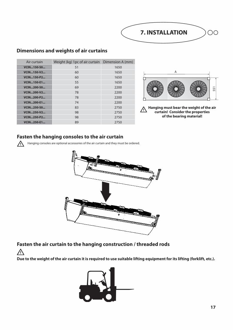
Fasten the hanging consoles to the air curtain Hanging consoles are optional accessories of the air curtain and they must be ordered.
Dimensions and weights of air curtains
Fasten the air curtain to the hanging construction / threaded rods
Due to the weight of the air curtain it is required to use suitable lifting equipment for its lifting (forklift, etc.).
Hanging must bear the weight of the air curtain! Consider the properties
of the bearing material!
Air curtain Weight (kg) 1pc of air curtain Dimension A (mm)VCIN...150-S0... 51 1650VCIN...150-V2... 60 1650VCIN...150-P2... 60 1650VCIN...150-E1... 55 1650VCIN...200-S0... 69 2200VCIN...200-V2... 78 2200VCIN...200-P2... 78 2200VCIN...200-E1... 74 2200VCIN...250-S0... 83 2750VCIN...250-V2... 98 2750VCIN...250-P2... 98 2750VCIN...250-E1... 89 2750
7. INSTALLATION
A
551

1818
7. INSTALLATION
Install threaded rods Threaded rods aren’t accessories of the air curtain and it is necessary to ensure them.
Install the air curtain using fork lift platformTIP: If the air curtain is packed horizontally, you can leave it in the package and lift the entire assembly up. After the securing of the
air curtain you bring the empty packaging down

19
Fasten to prepared threaded rods
Detail of fixing Secure properly against spontaneous loosening or falling
7. INSTALLATION

2020
7. INSTALLATION
Set the desired counterblow The setting of the counterblow is very important and influences the effect of screening. The recommended counterblow may be in the range 10-40 °.
Your partner in ventilation...
Produced in EU
125
CONTROL BEDIENUNG
Die Luftschleier werden ohne integrierte Regulation geliefert. Für ihre Regulierung wird folgendes Zubehör empfohlen.
INDESSE Industry
The company reserves the right of change without previous announcement. ©2VV, spol. s r.o.
AIR CURTAINS LUFTSCHLEIER
min.300mm
Anchoring structure (building delivery)Anchoring holder
Inle
tA
nsa
ug
en
1 module VCP-03-055
Ankerkonstruktion (Lieferung der Baustelle)Ankerhalter
1 Modul VCP-03-055
Vertical installation, side viewVertikale Installatin, Seitensicht
VCP-DH-01 horizontal holderHorizontalhalter
Horizontal installation, side viewHorizontale Installation, Seitensicht
Door openingTüröffung
Min
. 00 m
m3
Min. 00 mm3
The air curtains are shipped without integrated control system. The following accessories are recommended to allow their regulation.
INDESSE Industry
INDESSE Industry VCP-03
Anchoring holder Ankerhalter
VCP-DK-01
10° ~ 40°10° ~ 40°

21
VERTICAL FIXING OF THE AIR CURTAIN - MOVABLE BRACKET
Floor brackets are optional accessories of the air curtain and it is necessary to order them.
1) Measure the holes by using the holes in the bracket, which must be drilled into the floor
3) Fasten the upper part of the bracket to the air curtain
Připevněte pomocí dodaných šroubů k tomuto podstavci (6ks)
4) Fasten the upper part of the bracket to the bottom part of the bracket
Fasten by using screws supplied to this base
2) Spread the bracket and screw the bottom part to the ground
Installation material is not part of the air curtain. Ensure good quality material with respect to the installation place
7. INSTALLATION
Screw to the floor
Fasten to the air curtain

2222
7. INSTALLATION
VERTICAL FIXING OF THE AIR CURTAIN – MOBILE BRACKET Floor brackets are optional accessories of the air curtain and it is necessary to order them.
5) If the height of the air curtain (group of air curtains) exceeds 4m, then we recommend using an auxiliary bracket:
7) Set the required counterblow
By using a separate bracket you can set potential 10 ° on each side
The setting of the counterblow is very important and influences the effect of screening. The recommended counterblow of the whole air curtain including the base may be in the range 10-40 °.
6) The bracket may also serve as a link of 2 air curtains
Maximum permissible installation height of air curtains is 6.5 m. If you need a greater height, it is necessary to ensure the supporting construction
Air curtain 1
Air curtain 2
Bracket
40°
40°
10° 10°

23
VERTICAL FIXING OF THE AIR CURTAIN - STATIONARY BRACKET
Floor brackets are optional accessories of the air curtain and it is necessary to order them.
2) Measure the holes by using the holes in the bracket, that you subsequently drill into the floor
1) Install the brackets on the air curtain
Fasten by using screws supplied to this base (4 pieces)
3) Fasten the air curtain to the floor
The installation material is not part of the air curtain. Ensure a good quality material with respect to the installation place.
7. INSTALLATION

2424
7. INSTALLATION
VERTICAL FIXING OF THE AIR CURTAIN - STATIONARY BRACKET
Floor brackets are optional accessories of the air curtain and it is necessary to order them.
4) If the height of the air curtain (group of air curtains) exceeds 4m, then we recommend using an auxiliary bracket:
6) Set the required counterblow
By using a separate bracket you can set the potential at 10 ° on each side
The setting of the counterblow is very important and influences the effect of screening. The recommended counterblow of the whole air curtain may be in the range 10-40 °.
5) The bracket may also serve as a link of 2 air curtains
The maximum permissible installation height of the air curtains is 6.5 m. If you need a greater height, it is necessary to ensure the supporting construction.
Air curtain 1
Air curtain 2
Bracket
40°
40°

25
Flexible hosepipes with connection G1”.
The connection and pressure tests of the heater must be done by a person with expertise in plumbing and it must meet the applicable standards and regulations of the country.
The heat exchanger is designed for water, which may have a maximum temperature of + 110 ° C and a maximum pressure of 1.6 Mpa. At the inlet and outlet of the water heater it is recommended to install a shut-off valve for the possibility to shut off the water inlet.
The exchanger has outlets equipped with an external 1” thread and venting valve (A) and a tube for the placement of a temperature probe (B). Before final use, make sure that the water exchanger is completely vented.
Air curtains labeled P2 are equipped with an antifreeze protection sensor..
CONNECT HOSEPIPES OF WATER INLET AND OUTLET
7. INSTALLATION
A
B

2626
Regulation of water exchanger by three-way valve ZV-3
The regulation of the water exchanger must be dealt with separately.
• A detailed description of the regulation of the water exchanger by three-way valve (ZV-3),• including its installation can be found in manual to the three-way valve ZV-3.
ELECTRICAL DIAGRAM - ENGINES
1 2
TER-P
TER-P
ZV-3AA BB
AB
AB
ZV-3
M
Lopen(A-AB)
L(B-AB)
N
N
L
T
3
7. INSTALLATION
ECAC
Your partner in ventilation...
Produced in EU
HEATING UNITS LUFTERHITZERThe company reserves the right of change without previous announcement. ©2VV, spol. s r.o.
SAVANA SAV
336
L N PE
L N PE1 230V-
Wiring diagrams for the control system are provided in the manual.
Die Schaltpläne der Reglung sind in der Anleitung dargestellt.
Main electrical supplyElektrische Zuleitung
KEY TO CODING
SAV - 4 - V
V - rigid silver cover made of aluminium with “V-TECHNOLOGY” lamellas
D - silver cover with “Jet system”G - white cover (RAL 9010) with lamellas
31 - nominal output up to 1550 m /h (SAV-x-G)
32 - nominal output up to 2700 m /h34 - nominal output up to 4900 m /h36 - nominal output up to 6600 m /h
SAV - heating unit SAVANA
KENNZEICHNUNGSSCHLÜSSEL
SAV - 4 - V
V - silberes Aluminiumverdeck mit „V-TECHNOLOGIE“ der Lamellen
D - silberes Verdeck mit „System Düse“G - weiße Frontabdeckung (RAL9010) mit der
Lamellen
31 - die nominale Leistung 1550 m /St (SAV-x-G)
32 - die nominale Leistung 2700 m /St34 - die nominale Leistung 4900 m /St36 - die nominale Leistung 6900 m /St
SAV - Luftheizgerät SAVANA
0-10V
0-10V GND
27
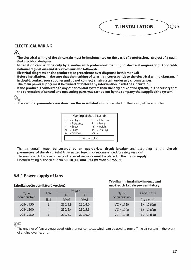
ELECTRICAL WIRING
• The electrical wiring of the air curtain must be implemented on the basis of a professional project of a quali-fied electrical designer.
• Installation can be done only by a worker with professional training in electrical engineering. Applicable national regulations and directives must be followed.
• Electrical diagrams on the product take precedence over diagrams in this manual!• Before installation, make sure that the marking of terminals corresponds to the electrical wiring diagram. If
in doubt, contact your supplier and do not connect an air curtain under any circumstances.• The main power supply must be turned off before any intervention inside the air curtain!• If the product is connected to any other control system than the original control system, it is necessary that
the connection of control and measuring parts was carried out by the company that supplied the system.
• The electrical parameters are shown on the serial label, which is located on the casing of the air curtain.
• The air curtain must be secured by an appropriate circuit breaker and according to the electric parameters of the air curtain! An oversized fuse is not recommended for safety reasons!
• The main switch that disconnects all poles of network must be placed in the mains supply.• Electrical rating of the air curtain is IP20 (E1) and IP44 (version S0, V2, P2).
6.5-1 Power supply of fans
Marking of the air curtain
Serial number
U = Voltagef = Frequencyn = Speedph = Phaseav = Air power
I = Total flowP = Powerm = WeightIP = IP ratingver =
Tabulka počtu ventilátorů ve cloně
• The engines of fans are equipped with thermal contacts, which can be used to turn off the air curtain in the event of engine overheating.
Tabulka minimálního dimenzování napájecích kabelů pro ventilátory
Type of air curtain
FanPower
AC EC[ks] [V/A] [V/A]
VCIN...150 3 230/3,9 230/4,0
VCIN...200 4 230/5,4 230/5,3
VCIN...250 5 230/6,7 230/6,9
Type of air curtain
Cabel CYSY
[ks x mm2]VCIN...150 3 x 1,0 (Cu)
VCIN...200 3 x 1,0 (Cu)
VCIN...250 3 x 1,0 (Cu)
7. INSTALLATION

2828
Power supply of electric heater:
Table of electric heater parametresTable of minimal sizing of power
cables of heaters
Type of the air curtain
Voltage Electric current
[V] [A]VCIN...150 400 35,2
VCIN...200 400 47,0
VCIN...250 400 58,6
Type of the air curtain
Cabel
[ks x mm2]VCIN...150 4 x 6
VCIN...200 4 x 10
VCIN...250 4 x 10
• Operating and emergency thermostat of the heater is already plugged in such a way that heaters will be discon-nected from the power supply in case of overheating. In case of failure of the emergency thermostat, it is neces-sary to replace the block of heaters because of the use of the melting fuse as protection.
7. INSTALLATION

29
Installation of the contactor box:• The contactor box is an optional accessory for the VCIN Type E2. Here’s how to install the contactor module:
7. INSTALLATION
1) Dismount the electrical box of the electric heater: 3) Put the contactor module on the screw terminal, screw it and tighten the entire screw terminal properly.
4) Connect according to the diagram and cover it with the box
2) Dismount the casing of the contactor module:

3030
8. FIRST USE
Before putting the air curtain into operation:• Make sure that any tools or other objects that could damage the air curtain didn’t remain in the air curtain.• Make sure that the electric power supply, regulation and inlet of heating water are properly supplied.• Make sure that the air curtain is properly covered.• Become familiar with the instructions of all used components.
Before putting the air curtain into operation, carefully read all the instructions for all components used in the system.
Test the regulation of the fan• Test the accuracy of the direction of fan rotation • Test the accuracy of the range of speed regulation• Test the fan behavior when using external elements
Test the regulation of electric heating• Test the functionality of the range of the heater’s regulation• Test the behavior of the heater when using external control elements
Test the regulation of water heating • Test the functionality of the range of the heater’s regulation• Test the behavior of the heater when antifreeze protection is activated• Test the behavior of the heater when using external control elements

31
• Compressed air, chemicals, solvents, water, or sharp objects are forbidden to use for cleaning. • You can clean the water exchanger and the inside of the air curtain with a soft brush or vacuum cleaner.• For cleaning the unit’s casing it is best to use a cloth and soapy water
PERIODIC INSPECTIONS OF THE AIR CURTAIN
It is recommended to perform a periodic inspection of the status of the curtain after every 500 hours of operation, and also before and after the heating season.
- inspection of pollution of the water exchanger- inspection of the status of the fan (especially the functionality of the fan and bearings)- leak test of the water exchanger and connections- inspection of the curtain whether it is damaged in any way (especially fan basket)- inspection of tightening of screw connections, especially consoles- inspection of the status of the filter (which may be more frequent due to the installation conditions)
Cleaning procedure
1) Dismount the section of fans from a casing of the unit
3) Clean the water exchanger (if the air curtain has one)
4) Replace the fans back2) Clean the fans on all sides carefully
9. MAINTENANCE
The main electrical power supply (for fan + heater) must be shut down during maintenance of the heating unit. Before maintenance it is necessary to let the air curtain cool down! When handling the unit, it is neces-sary to use protective gloves against injury by sharp edges!
The following procedure illustrates the cleaning of one section of fans.Cleaning needs to be done on all the fans.

3232
If you are unsure of the correctness of steps, do not attempt to perform any repairs and contact profes-sional service!!!
If you are unable to discover the defect, remove it or the intervention into the device is required, please contact authorized service!
Behavior of device Supposed problem Solution
The device is noisy
Air in the exchanger
Vent the heat exchanger by using the venting screws.
Shut-off valves on the device are not fully open. Open the shut-off valve fully.
Damaged bearings of the fan. The impeller has its own will, or vice versa it cannot rotate freely.
It is necessary to dismantle and change the fan bearings at an author-ized service, or change the entire fan.
Unbalanced impeller of the fan rotates freely but when you turn it on the fan it vibrates.
Dismantle the fan and take it to professional service for balancing.
Insufficient heating out-put of the air curtain
Air in the exchanger of the curtain.
Vent the heat exchanger by using the venting screws.
The exchanger is very dirty.
Dismantle the fan and clean the exchanger. It is convenient to use hot water or steam to clean. Do not use aggressive detergents.
Shut-off or control valves on the device are not fully open.
Open the shut-off valves fully, check if the control valve is in the open position.
Wrong direction of the rotation of the mixing valve.
Repair the electrical wiring in the screw terminal of the regulation.
Clogged filter (if installed) Change the filter or clean the filter.
Thermostat on electric heating rod is open Check heating elements
10. TROUBLESHOOTING
33
10. TROUBLESHOOTING
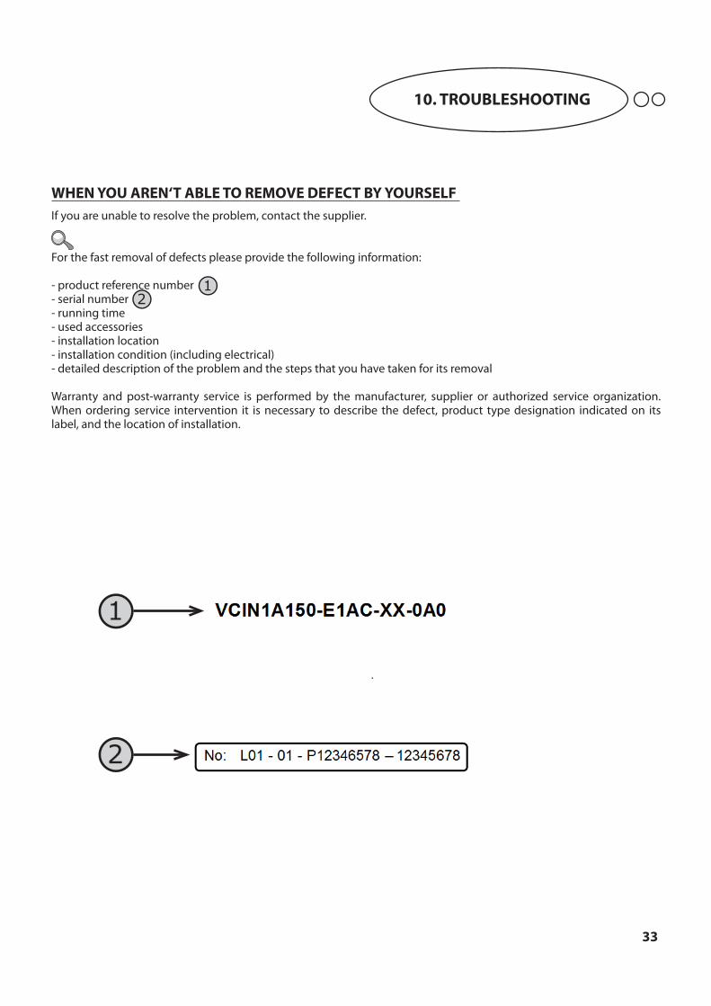
WHEN YOU AREN‘T ABLE TO REMOVE DEFECT BY YOURSELF If you are unable to resolve the problem, contact the supplier.
For the fast removal of defects please provide the following information:
- product reference number - serial number - running time- used accessories- installation location- installation condition (including electrical)- detailed description of the problem and the steps that you have taken for its removal
Warranty and post-warranty service is performed by the manufacturer, supplier or authorized service organization. When ordering service intervention it is necessary to describe the defect, product type designation indicated on its label, and the location of installation.
12
1
2
3434
11. PRODUCT DISPOSAL
Space for your notes:
PUTTING THE PRODUCT OUT OF OPERATION - DISPOSALBefore disposing of the product, make the product unusable. Even old products contain raw materials that can be reused. Take them to a collection point of secondary raw materials.The product is good to dispose at the place, which is specialized for it, and thus it will be possible to recycle materials. Store unusable parts of the product at a controlled dump.
When disposing of materials, it is necessary to observe the relevant national regulations on waste disposal.

35
12. IN CONCLUSION
Read all instructions for proper and safe usage and follow them..
Regarding any questions or requests for clarifi-cation, do not hesitate to contact our sales de-partment or technical support department.
Space for your notes:
Kontakt:
2VV, s.r.o.Poděbradská 289530 09 PardubiceCzech Republic
Internet:http://www.2vv.cz

Copyright © 2VVAll rights reserved.
Producer is not liable for damage to equipment caused by improper installation and operation, which are contrary to the instructions and contrary to common practice in the installation and operation
of air handling units and regulation systems.
Here stick the label, which you can find in accessories, for the future problem solving.