industrial gas piping system for chemical …umpir.ump.edu.my/9453/1/cd8322.pdf · chemical...
TRANSCRIPT

III
INDUSTRIAL GAS PIPING SYSTEM FOR
CHEMICAL ENGINEERING LABORATORY
UNIVERSITI MALAYSIA PAHANG
ROSMIMIE BINTI ABDULLAH
Thesis submitted in partial fulfilment of the requirements
for the award of the degree of
Bachelor of Chemical Engineering (Gas Technology)
Faculty of Chemical & Natural Resources Engineering
UNIVERSITI MALAYSIA PAHANG
JULY 2013
©ROSMIMIE BINTI ABDULLAH (2013)

VIII
ABSTRACT
Industrial gas piping system for Faculty of Chemical and Natural Resources
Engineering (FKKSA) laboratory is used to supply industrial gas to the equipments in
clean room laboratory. The gases that are supplied to the laboratory are Nitrogen (N2),
Carbon Dioxide (CO2), Oxygen (O2), Hydrogen (H2), Helium (He), Compressed Air,
Nitrous Oxide (N2O), Acetylene (Ace) and Argon (Ar). These gases are used for
specific equipment such as fermenter, gas chromatography (GC), and Atomic
Absorption Spectroscopy (AAS).These equipments are used for research and training.
The piping systems are generally stainless steel tubing with 3/8 inch and 1/4 inch tube
outside diameters. There are five rooms in the cleanroom laboratory that involved with
piping system, and they are BioTech Analytical Laboratory, BioTech Animal & Plant
Cell Culture Room, BioTech Processing Scale Up Laboratory 1, BioTech Processing
Scale Up Laboratory 2, Analytical Hot Laboratory, and Analytical Cool Laboratory.
Generally, part of this piping system has already stopped from operating because of
suspected leakage occurring in the system. This leakage can contribute to the economic
loses as the gas escaped to the surrounding continuously. As small quantity of gases
escape will greatly affect the cost (F. J. Callahan, 1993). There are cases where gases
are supplied directly from cylinder to the equipment without a proper piping system.
This is not complying with MS 830 clause 11.3 “the cylinder shall not be stored in a
building or part thereof or structures attached thereto when the building is used as an
educational institution”. The consequence from this non-compliance may cause the
possibilities of inhaled gases by the public and lead to suffocation from the
accumulation of flammable or reactive gases. In order to solve the problem, leak test
should be conducted. However, this is not simple. It should be done with correct
procedure by referring to appropriate standard. Similar goes to the cylinder storage area,
it does not have enough signage as stated by MS 830 clause 10.7 “the messages in the
form of signs shall be clearly displayed at the storage area”. The warning notice shall be
in letters of at least 50mm high. Thus, this research is aim to identify the safety of the
existing industrial gas piping system at selected laboratory and also to improve the
existing system based on acceptable standards.
Basically in this research, it involves site surveying, measurement, collecting data,
discussion and documentation. Start with measuring the length of piping in selected
room using measuring tape as the original drawing of the system was missing. Then, the
drawing of the system is done by using AutoCAD. Next is to calculate the number of
cylinder needed for the leak test for the piping system. After the calculation, the cost of
leak test was estimated. Then, step by step procedure to conduct leak test are performed
according to ASME B31.3. This procedure can be a reference to laboratory owners who
want to conduct leak test in the future. The analysis of the safety in for the system is
also carried out.
From calculation, it shows that the volume of gas needed for test is 34281 ft3 at
atmospheric pressure which is equal to 228 ft3 at 2200 psig. From this volume, supply
pressure can be calculated and for all piping, the supply pressure calculated is generally
higher than test pressure. Thus, only one cylinder is needed for all piping system. For
safety analysis, it showed that eighteen items is complying with standards and ten items
is not complying with the standards. This should be improved so that the system is safe
to be used in the laboratory.

X
TABLE OF CONTENTS
SUPERVISOR‟S DECLARATION ............................................................................... IV
STUDENT‟S DECLARATION ...................................................................................... V
Dedication ....................................................................................................................... VI
ACKNOWLEDGEMENT ............................................................................................. VII
ABSTRACT ................................................................................................................. VIII
ABSTRAK ...................................................................................................................... IX
TABLE OF CONTENTS ................................................................................................. X
LIST OF FIGURES ....................................................................................................... XII
LIST OF TABLES ....................................................................................................... XIII
LIST OF ABBREVIATIONS ...................................................................................... XIV
1 INTRODUCTION .................................................................................................... 1
1.1 Motivation and statement of problem ................................................................ 1
1.2 Objectives ........................................................................................................... 2
1.3 Scope of this research ......................................................................................... 2
1.4 Main contribution of this work .......................................................................... 2
1.5 Organisation of this thesis .................................................................................. 3
2 LITERATURE REVIEW ......................................................................................... 4
2.1 Overview ............................................................................................................ 4
2.2 Introduction ........................................................................................................ 4
2.3 Components and fittings used in existing gas piping system ............................. 7
2.3.1 Pressure regulator ....................................................................................... 8
2.3.2 Pressure gauge ............................................................................................ 9
2.3.3 Valve ......................................................................................................... 10
2.3.4 Fittings ...................................................................................................... 12
2.4 Pressure test method ......................................................................................... 16
2.4.1 Pneumatic test ........................................................................................... 16
2.4.2 Leak test solution ...................................................................................... 17
2.4.3 Test Procedure (According to ASME B31.3) ........................................... 17
2.4.4 Safety precaution during conducting the test ............................................ 17
2.4.5 Gas cylinder .............................................................................................. 18
2.4.6 Specific Hazard Class ............................................................................... 19
2.5 Industrial gases ................................................................................................. 20

XI
2.5.1 Helium gas ................................................................................................ 20
2.5.2 Carbon dioxide .......................................................................................... 20
2.5.3 Oxygen ...................................................................................................... 21
2.5.4 Nitrogen .................................................................................................... 21
2.5.5 Hydrogen .................................................................................................. 22
2.5.6 Nitrous Oxide ............................................................................................ 23
2.5.7 Acetylene .................................................................................................. 23
2.5.8 Argon ........................................................................................................ 24
2.5.9 Compressed Air ........................................................................................ 24
2.6 General Code and Standard used ..................................................................... 24
2.6.1 Code and standard used ............................................................................ 25
3 MATERIALS AND METHODS ............................................................................ 26
3.1 Introduction ...................................................................................................... 26
3.2 Collecting data ................................................................................................. 27
3.4 Analysing ......................................................................................................... 29
3.3 Documentation ................................................................................................. 31
4 RESULTS AND DISCUSSION ............................................................................. 32
4.1 Overview .......................................................................................................... 32
4.2 Introduction ...................................................................................................... 32
4.3 Result on Test Medium for Leakage Test ........................................................ 32
4.3.1 Drawing using AutoCAD ......................................................................... 32
4.3.2 Calculation of volume of test material needed for leak test ..................... 32
4.3.3 Estimation of the Cost of Leak Test ......................................................... 41
4.4 Result for Safety Observation on the Existing Piping System ......................... 43
4.4.1 Safety analysis of the system .................................................................... 49
4.4.2 Recommendation ...................................................................................... 52
5 CONCLUSION ....................................................................................................... 54
5.1 Conclusion........................................................................................................ 54
5.2 Future work ...................................................................................................... 54
REFRENCES .................................................................................................................. 55
APPENDICES ................................................................................................................ 57

XII
LIST OF FIGURES
Figure 2-1: Pressure regulator used in the existing system .............................................. 9
Figure 2-2: Pressure gauge ............................................................................................. 10
Figure 2-3: Isolation/Needle Valve ................................................................................. 11
Figure 2-4: Fujikin Ball Valve ........................................................................................ 12
Figure 2-5: Fujikin Plug Valve ....................................................................................... 12
Figure 2-6: Swagelok Union ........................................................................................... 13
Figure 2-7: Swagelok Reducing Union .......................................................................... 13
Figure 2-8: Swagelok Tee ............................................................................................... 14
Figure 2-9: Swagelok Reducing Union Tee ................................................................... 14
Figure 2-10: Swagelok Union Elbow ............................................................................. 15
Figure 2-11: Swagelok Cap ............................................................................................ 15
Figure 2-12: Proper Safety Attire in Handling Gas Cylinder ......................................... 18
Figure 3-1: Measuring Tape ........................................................................................... 27
Figure 3-2: Parts of Existing Piping System ................................................................... 28
Figure 4-1: Helium Gas Piping System .......................................................................... 35
Figure 4-2: Nitrous Oxide Piping System ....................................................................... 36
Figure 4-3: Oxygen Piping System ................................................................................. 37
Figure 4-4: Carbon Dioxide Piping System .................................................................... 38
Figure 4-5: Nitrogen Piping System ............................................................................... 39
Figure 4-6: Nitrogen Cylinder Gas (Source: ASCOTORCH.com) ................................ 41
Figure 4-7: Snoop Solution for Leak Test (Source: Swagelok Malaysia) ...................... 42
Figure 4-8: Laboratory Layout ....................................................................................... 43
Figure 4-9: Hazard Signage ............................................................................................ 52
XIII
LIST OF TABLES
Table 2-1: Specification of the Existing System .............................................................. 5
Table 2-2: List of equipment in the laboratory ................................................................. 6
Table 2-3: Quantity of Components and Fittings ............................................................. 7
Table 2-4: Quantity of Components and Fittings ............................................................. 8
Table 3-1: Size and Volume of Nitrogen at Given Pressure ........................................... 29
Table 4-1: Summary of Pipe Volume Calculation .......................................................... 40
Table 4-2: Summary Leak Test Detection ...................................................................... 40
Table 4-3: Gas Storage 1,2 and 3 .................................................................................... 44
Table 4-4: Biotech Processing Scale Up Lab 1 .............................................................. 45
Table 4-5: Analytical Cool Lab ...................................................................................... 46
Table 4-6: Analytical Hot Lab ........................................................................................ 47
Table 4-7: Bio Micro Lab ............................................................................................... 48
Table 4-8: Animal Cell Room ........................................................................................ 48
Table 4-9: Safety Analysis of the System ....................................................................... 40
Table 4-2: Summary Leak Test Detection ...................................................................... 40
Table 4-2: Summary Leak Test Detection ...................................................................... 40
Table 4-2: Summary Leak Test Detection ...................................................................... 40

XIV
LIST OF ABBREVIATIONS
ASME American Society of Mechanical Engineers
MS Malaysian Standard
AAS Atomic Absorption Spectroscopy
GC Gas Chromatography
MAWP Maximum Allowable Working Pressure
ISO International Standards Organization

1
1 INTRODUCTION
1.1 Motivation and statement of problem
Chemical Engineering Laboratory, University Malaysia Pahang is using piping system
to supply industrial gases to the equipment in the clean room. The gases that was supply
in the laboratory was Nitrogen (N2), Carbon dioxide (CO2), Oxygen (O2), Hydrogen
(H2), Helium (He), Compressed Air, Nitro Oxide (N2O), Acetylene (Ace) and Argon
(Ar). These gases were used for specific equipment such as fermenter, gas
chromatography (GC) and Atomic Absorption Spectroscopy (AAS). The existing gas
piping system is using manifold system. The capacity of each cylinder used is about 50
liter water capacity. The diameter of the cylinder is approximately 230 millimeter. In
general, this existing industrial gas piping system is not effective as there were some
leakage occurs in the pipeline system.
This project is conducted because there is some problems occur on the existing gas
piping system. The leakage of the system causes the gas supplied directly from the
cylinder to the equipment as the gas piping system is no longer can be used. This type
of connecting is not complying with standard. According to MS 830, the cylinder
cannot bring into a confined space to avoid inhaling the gas and possible suffocation
from the accumulation of flammable, toxic or reactive gases. Besides that, the leakages
also contribute to the economic losses as the gas is escape to the surrounding. A small
quantity of gases escape will affect greatly as the gas is continuously used. This system
can be improved by repairing or replace some of the parts from the system with new
one.
Another problem in the existing system is the installation of the system is not
completely complying with standard. According to MS 830, 2003 the cylinder storage
shall be stored away from drain. However, the storage of cylinder at FKKSA laboratory
is beside the drain. In addition, the storage also does not have enough signs displayed.
According to standard, the signs and notices shall be clearly displayed at the storage
area. The signs need to be displayed are no smoking sign, no naked light sign, nearby
material is a fire risk sign and no hand phone sign.

2
Site visit has been done on the industrial gas piping system for Chemical Engineering
Laboratory, University Malaysia Pahang. This project is to improve the existing
industrial gas piping system for FKKSA laboratory to make it more systematic, safe,
and to overcome all the weaknesses of the existing system. Basically it involves site
surveying, measurement, collecting data, discussion and documentation.
1.2 Objectives
The following are the objectives of this research:
o To determine the volume of test medium needed for leakage detection on
existing piping system in order to improve the integrity of the piping system
o To identify the safety noncompliance of the existing industrial gas piping system
at selected laboratory
1.3 Scope of this research
In order to improve the existing gas piping system, the scope of research is more
focusing on:
i) Determines the weaknesses of the system and makes some recommendation
to enhance the existing piping system
ii) Surveying whether the system is comply with standards or not
iii) Study on how to detect leakage on the system and calculate the required
capacity of inert gas (Nitrogen) needed for the leak test
iv) Draw existing gas piping system as the original drawing is missing to
measure the length of the pipe
1.4 Main contribution of this work
This project is very useful for chemical engineering laboratory, University Malaysia
Pahang because this project will come out with a solution and also some
recommendation to improve the system. Besides that, it will be more effective and safe
to use. Importantly, at the end of this project, the drawing of the entire existing gas
piping system will be done. Since the old drawing is missing, the new drawing can be a
reference before doing leak test and for future piping planning.

3
1.5 Organisation of this thesis
The structure of the reminder of the thesis is outlined as follow:
Chapter 2 provides a literature review of this research. The literature review is based on
the existing piping system at laboratory. Site visit to the laboratory is done in order to
collect data. From all the data, literature review can be done. Besides that, in this
chapter also review the theoretical and methodology that contribute to this research. The
theory and method is generally based on company standard and applicable standard
such as ASME, MS 830 and soon. Furthermore, it also explains about the properties of
every gas that used in the laboratory. Most importantly, the theory about the leakage
causes is also stated in this chapter.
Chapter 3 gives a methodology that used for this research. Basically this research
involves site surveying, measurement, collecting data, discussion and documentation.
Begin with a visit to cleanroom to collect data for this project. The length of pipe is
measured. Besides that, all fittings used in existing piping system is recorded. Next, the
drawing for existing gas piping system is draw using AutoCAD. Lastly, an investigation
is conducted to determine the safety of the existing system. Then all data is documented
in this thesis.
Chapter 4 is the heart of the thesis which consist of result and discussion of the research.
The result shows the drawing of the existing piping system using AutoCAD with
appropriate symbol. Then, the length of the pipe is tabulated in the table as well as the
volume of pipe. This chapter also describe the steps to calculate the number of cylinder
need for the leak test.
Chapter 5 draws together a summary of the thesis and outlines the future work which
can be done to improve the research.

4
2 LITERATURE REVIEW
2.1 Overview
In this review, there are three important topics that will be discussed. First, review on
background of the existing industrial gas piping system. Second, the data collected on
the existing system. Last but not least, the data that will be used to calculate the test
medium needed for leak test.
2.2 Introduction
This literature review is based on the system and design of the existing industrial gas
piping system in FKKSA laboratory. In this chapter, all the equipment and fittings used
in the existing system is explained. Besides that, the information on safety and leakage
is clearly stated based on applicable standard.
2.3 Background on the existing industrial gas piping system
The industrial gas piping system in FKKSA laboratory was generally used products
from Swagelok. The system mainly used 3/8 in. and 1/4 in. tube OD size. The tube
material used is stainless steel. The operating pressure of this existing piping system is
1.5 bars. Design pressure is unknown as the existing drawing for the system is missing.
Therefore, the design pressure is estimated by taking pressure regulator reading. From
that reading, it shown that the highest reading for outlet pressure is 5 bars. Assume 5
bars as maximum allowable working pressure (MAWP). Design pressure is the
maximum pressure that the system that can be exposed to and sets the system relief
valve at the same pressure. This should be below MAWP and based on company
standards can vary from 10% to 25% above the maximum operating pressure of the
system. Thus, take 25% above MAWP, so the design pressure will be 6.25 bars. This
piping was used to supply gas to the equipment in the laboratory. The gases used are
compressed gases. The pipe length to supply the gases was quite long. However, parts
of the pipeline was no longer can be used. This problem occurs since year 2012. The
laboratory owner connects the gas cylinder to the line. However, the cylinder is empty
within one day. It shows that leakage is occurring on the system. The leakage might due
to corrosion of the tube. The internal or external corrosion of the tube can reduce the

5
wall thickness that can eventually develop into a leakage (E. S. Menon, 2011).
Moreover, fitting failures such as valve and pressure regulator can also contribute to the
leakage. Some pressure regulators are very sensitive. In addition, the system failure
might also be due to the seals that connect to the piping are corroded. Usually a major
leak occurs at the fitting where seals are used to connect the pipe and the fittings. The
analysis will be carried out to calculate the test medium needed and the cost required for
leak test. Table 2-1 below shows the specification of the existing system.
Table 2-1: Specification of the Existing System
No Item Specification
1 Tube material 316 Stainless steel
2 Tube diameter 1/4 inch, 3/8 inch, 1/2 inch
3 Operating pressure 1.5 bar
4 Pressure regulator Inlet pressure 206 bar
Outlet pressure 5 bar
5 Jointing Seamless
6 Ball valve Fujikin & Swagelok
7 Paint Dark red
There are five rooms in cleanroom laboratory that involved piping system which are
BioTech Analytical Laboratory, BioTech Animal & Plant Cell Culture Room, BioTech
Processing Scale Up Laboratory 1, BioTech Processing Scale Up Laboratory 2,
Analytical Hot Lab, and Analytical Cool Lab. These rooms consist of different
equipment that used for training and research by students as well as lecturers. Table 2-2
shows the list of equipment in the laboratory.

6
Table 2-2: List of equipment in the laboratory
No Equipment Brand / Model Status Location
1 Atomic Absorption
Spectrometer (AAS)
Model Z-5000
Series Polarized
Zeeman
(HITACHI)/Japan Existing
equipment Analytical
Cool Lab 2
Differential Scanning
Calorimeter DCS Q1000
3 Surface Tension Analyzer Surfer Analyzer New
equipment
4 Gas Chromatography-
mass spectrometry
Agilent 5975C
MSD G 3171A
Existing
equipment
Analytical
Hot Lab
5 Gas Chromatography Agilent G 3440A
6 Gas Chromatography Agilent G 890N
7 Gas Chromatography
(Thermo)
Agilent K
0723B001 300000
8 Fermenter 20L Sartorius Bio stat C
Biotech
Processing
Scale up
Lab
9 Fermenter 20L Sartorius Bio stat D
10 Bactron Anaerobic
Chambers
New
equipment
11 Laminar Air Flow ESCO AHC-4AI
Existing
equipment
Bio Macro
Lab
12 CO2 Incubator - Animal Cell
Room

7
2.3 Components and fittings used in existing gas piping system
Generally, Swagelok tube fitting is a sequential phase, controlled action sealing and
gripping device. It consisting wide variety of configuration making it as the first choice.
All fitting is used from Swagelok Company and the component, such as valve is used
from Fujikin and also from Swagelok. There are two types of pressure regulator used in
this existing piping system which is single stage pressure regulator and double stages
pressure regulator. The number of components and fittings used in the existing system
is tabulated in the Table 2-3 below:
Table 2-3(a): Quantity of Components and Fittings
Pipe
length
Pressure
regulator
Ball
valve Union
Branch
Tee
H2 27090 3 3 4 2
He 28400 4 4 6 2
N2 32040 5 5 5 1
O2 22780 2 2 5 1
Compressed air 31580 6 6 4 3
N2O 16256 3 3 1 2
Ace 16495 3 3 1 2
Ar 17030 4 4 0 2
O2 line 2 56745 1 3 2 1
CO2 line 2 56924 1 3 2 1
N2 line 2 57263 1 4 2 1
Total 362603 33 40 32 18

8
Table 2-4(b): Quantity of Components and Fittings
Elbow Reducing
tee
Pressure
Gauge Cap
H2 0 0 4 0
He 0 1 6 0
N2 1 1 5 0
O2 0 0 2 0
Compressed air 1 1 6 0
N2O 0 0 3 0
Ace 0 0 3 0
Ar 0 1 5 0
O2 line 2 0 3 1 1
CO2 line 2 0 3 1 1
N2 line 2 0 3 1 0
Total 2 13 37 2
2.3.1 Pressure regulator
Pressure regulator limits excess inlet gas pressure to a constant outlet pressure. It
controls outlet pressure by balancing an adjustable spring force against the forces
caused by inlet and outlet pressures. The spring force is adjusted by turning the handle,
which sets the desired outlet pressure. There are two types of pressure regulator which
are single stage regulator and double stage regulator. Single stage regulator contains a

9
single diaphragm and poppet. The high pressure gas enters the regulator through the
inlet pressure chamber. It passes into the low pressure chamber through the valve stem.
The flow is adjusted by turning the regulating knob. Turning it clockwise compresses
the diaphragm which pushes the valve stem open, so increasing the gas flow through the
regulator. Two stage regulators work in much the same way as single stage regulators
with one main difference. Rather than having one diaphragm and poppet, they have two.
The first stage reduces the pressure, but as the cylinder empties, the pressure exerted on
the first stage decreases allowing the flow to increase. This second stage is constructed
in a similar manner to the first, but the pressure being exerted on the second diaphragm
and valve stem is less.
2.3.2 Pressure gauge
Pressure gauge is a measurement device which determines the pressure in a compressed
gas or liquid. Pressure gauges are widely used all over the world, for instance,
monitoring the pressure in a process. There are many different styles of pressure gauge
available, designed for various purposes. Like others measurement device, these gauges
can and should be calibrated periodically to confirm that they are working correctly
when they are used for sensitive operations. Whatever various forms and materials they
use, a pressure gauge is designed to measure pressure from gases, liquids, vapour‟s or
solid bodies in many applications and industries. Due to the volatile nature some of
these sources can take, pressure gauges and pressure instruments can fail for a multitude
of reasons. Protecting and inspecting pressure instruments on a regular basis will help
prevent failure and keep operations running smoothly.
Figure 2-1: Pressure regulator used in the
existing system
10
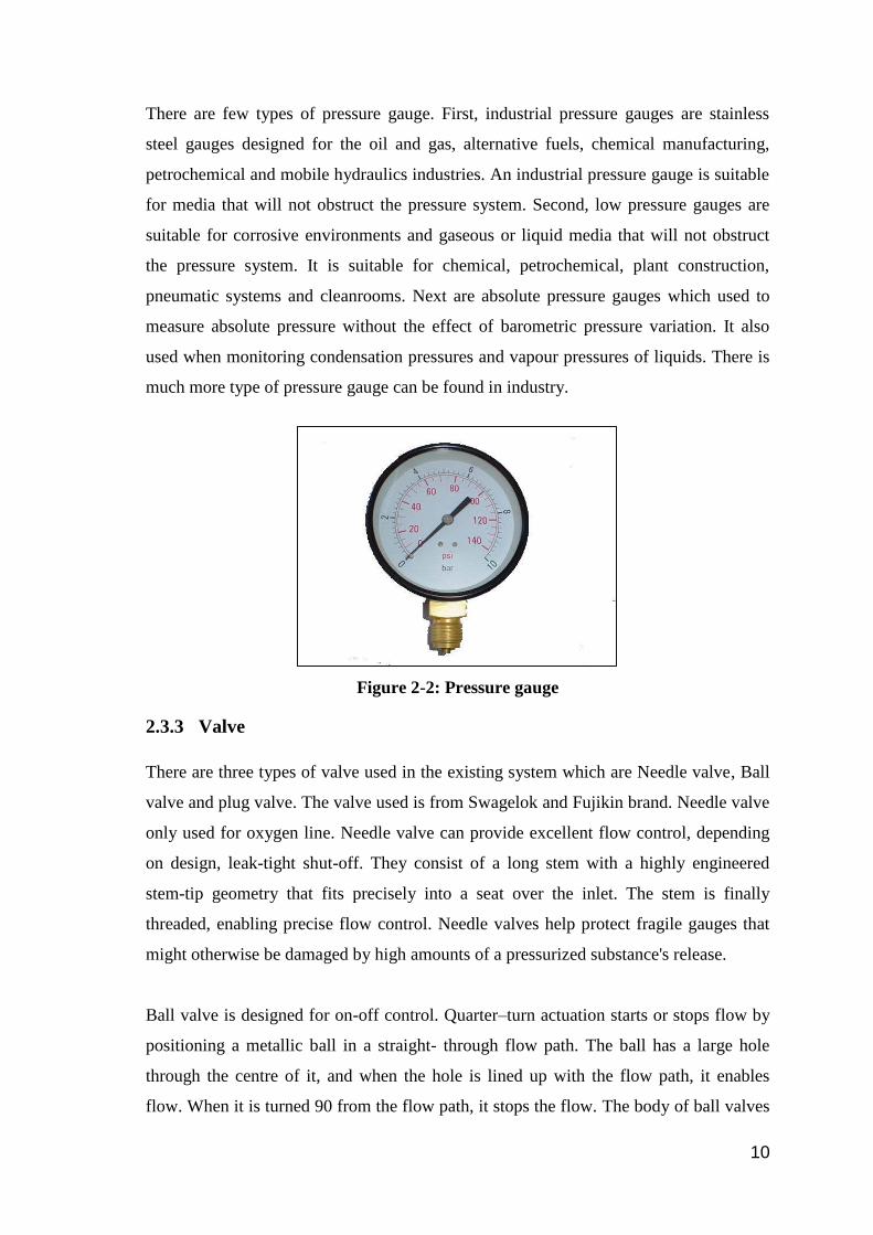
There are few types of pressure gauge. First, industrial pressure gauges are stainless
steel gauges designed for the oil and gas, alternative fuels, chemical manufacturing,
petrochemical and mobile hydraulics industries. An industrial pressure gauge is suitable
for media that will not obstruct the pressure system. Second, low pressure gauges are
suitable for corrosive environments and gaseous or liquid media that will not obstruct
the pressure system. It is suitable for chemical, petrochemical, plant construction,
pneumatic systems and cleanrooms. Next are absolute pressure gauges which used to
measure absolute pressure without the effect of barometric pressure variation. It also
used when monitoring condensation pressures and vapour pressures of liquids. There is
much more type of pressure gauge can be found in industry.
Figure 2-2: Pressure gauge
2.3.3 Valve
There are three types of valve used in the existing system which are Needle valve, Ball
valve and plug valve. The valve used is from Swagelok and Fujikin brand. Needle valve
only used for oxygen line. Needle valve can provide excellent flow control, depending
on design, leak-tight shut-off. They consist of a long stem with a highly engineered
stem-tip geometry that fits precisely into a seat over the inlet. The stem is finally
threaded, enabling precise flow control. Needle valves help protect fragile gauges that
might otherwise be damaged by high amounts of a pressurized substance's release.
Ball valve is designed for on-off control. Quarter–turn actuation starts or stops flow by
positioning a metallic ball in a straight- through flow path. The ball has a large hole
through the centre of it, and when the hole is lined up with the flow path, it enables
flow. When it is turned 90 from the flow path, it stops the flow. The body of ball valves

11
may be made of metal, plastic or metal with a ceramic centre. The ball is often chrome
plated to make it more durable. Ball valves are used extensively in industrial
applications because they are very versatile, supporting pressures up to 1000 bar and
temperatures up to 482°F (250°C). Sizes typically range from 0.2 to 11.81 inches (0.5
cm to 30 cm). They are easy to repair and operate. In this existing piping system, ball
valve used is from Fujikin. Figure 2-4 shows the specification of the valve.
Plug valves are either cylindrical or conically tapered. Conical valves are equipped with
a handle attached to one end of the plug which allow better handling and control of the
flow of the fluid whenever the device is opened or closed. There are many different
models of plug valves, and among them is the two-port valve, which is simple to use
and allows the fluid or gas to flow whenever it is opened, as well as stop the flow each
time the valve is shut closed.
Type: Isolation / Needle valve
Size: 3/8”
Connection: Compression
Wetted Material: 316 Stainless Steel
Seats and Seals: PTFE
Pressure Range PSIG: Up to 5000
Temperature Rating: Up to 450
Flow Coefficient (Cv): 0.73
Figure 2-3: Isolation/Needle Valve
12
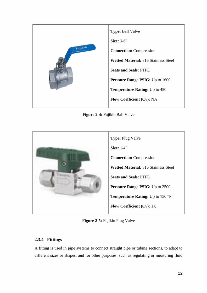
Type: Ball Valve
Size: 3/8”
Connection: Compression
Wetted Material: 316 Stainless Steel
Seats and Seals: PTFE
Pressure Range PSIG: Up to 1600
Temperature Rating: Up to 450
Flow Coefficient (Cv): NA
Figure 2-4: Fujikin Ball Valve
Type: Plug Valve
Size: 1/4”
Connection: Compression
Wetted Material: 316 Stainless Steel
Seats and Seals: PTFE
Pressure Range PSIG: Up to 2500
Temperature Rating: Up to 150 °F
Flow Coefficient (Cv): 1.6
Figure 2-5: Fujikin Plug Valve
2.3.4 Fittings
A fitting is used in pipe systems to connect straight pipe or tubing sections, to adapt to
different sizes or shapes, and for other purposes, such as regulating or measuring fluid
13
flow. There are five types of fittings used in the existing piping system. These fittings
are from Swagelok. The specification of the fittings is shown in figure below:
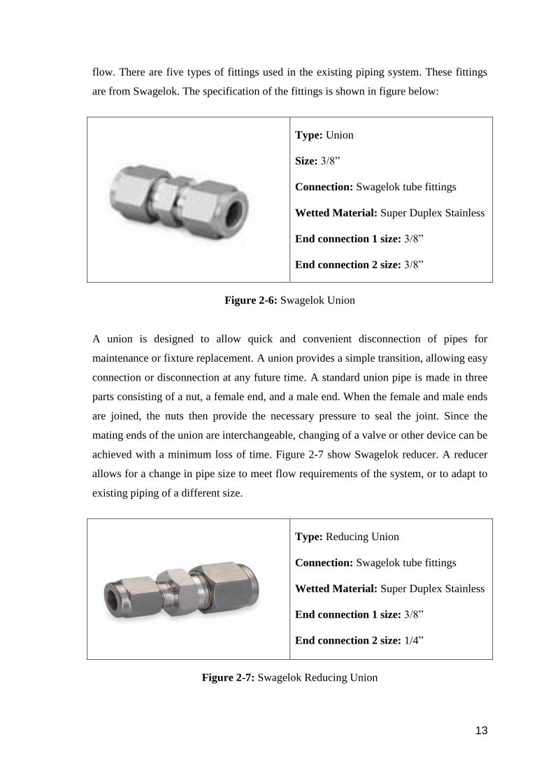
Type: Union
Size: 3/8”
Connection: Swagelok tube fittings
Wetted Material: Super Duplex Stainless
End connection 1 size: 3/8”
End connection 2 size: 3/8”
Figure 2-6: Swagelok Union
A union is designed to allow quick and convenient disconnection of pipes for
maintenance or fixture replacement. A union provides a simple transition, allowing easy
connection or disconnection at any future time. A standard union pipe is made in three
parts consisting of a nut, a female end, and a male end. When the female and male ends
are joined, the nuts then provide the necessary pressure to seal the joint. Since the
mating ends of the union are interchangeable, changing of a valve or other device can be
achieved with a minimum loss of time. Figure 2-7 show Swagelok reducer. A reducer
allows for a change in pipe size to meet flow requirements of the system, or to adapt to
existing piping of a different size.
Type: Reducing Union
Connection: Swagelok tube fittings
Wetted Material: Super Duplex Stainless
End connection 1 size: 3/8”
End connection 2 size: 1/4”
Figure 2-7: Swagelok Reducing Union

14
Type: Tee
Size: 3/8”
Connection: Swagelok tube fittings
Wetted Material: Super Duplex Stainless
End connection 1 size: 3/8”
End connection 2 size: 3/8”
Figure 2-8: Swagelok Tee
A tee is the most common pipe fitting. It is available with all female thread sockets, all
solvent weld sockets, or with opposed solvent weld sockets and a side outlet with
female threads. It is used to either combine or split a fluid flow. It is a type of pipe
fitting which is T-shaped having two outlets, at 90° to the connection to the main line. It
is a short piece of pipe with a lateral outlet. A tee is used for connecting pipes of
different diameters or for changing the direction of pipe runs. They are made of various
materials and available in various sizes and finishes. They are extensively used in
pipeline networks to transport two-phase fluid mixtures. When the size of the branch is
same as header pipes, equal tee is used and when the branch size is less than that of
header size, reduced tee will be used. Figure 2-9 show reducing tee from Swagelok.
Type: Reducing Union Tee
Connection: Swagelok tube fittings
Wetted Material: 316 Stainless Steel
Connection 1 size: 3/8”
Connection 2 size: 1/4”
Connection 3 size: 3/8”
Figure 2-9: Swagelok Reducing Union Tee
15
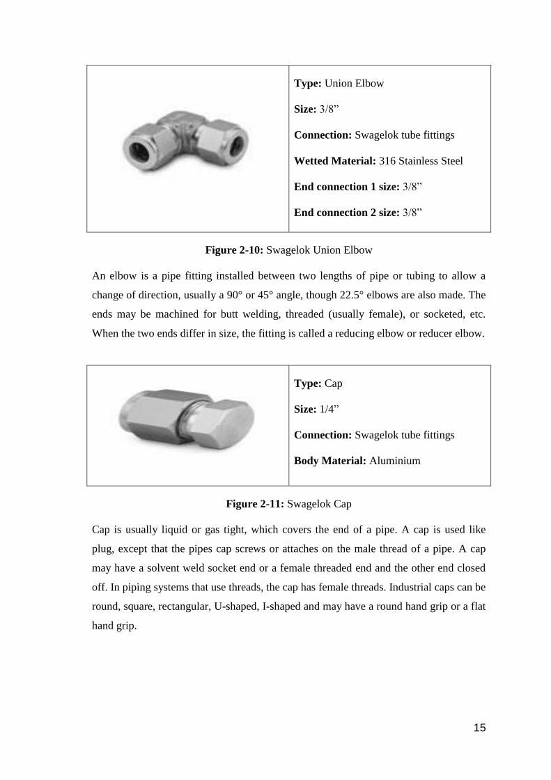
Type: Union Elbow
Size: 3/8”
Connection: Swagelok tube fittings
Wetted Material: 316 Stainless Steel
End connection 1 size: 3/8”
End connection 2 size: 3/8”
Figure 2-10: Swagelok Union Elbow
An elbow is a pipe fitting installed between two lengths of pipe or tubing to allow a
change of direction, usually a 90° or 45° angle, though 22.5° elbows are also made. The
ends may be machined for butt welding, threaded (usually female), or socketed, etc.
When the two ends differ in size, the fitting is called a reducing elbow or reducer elbow.
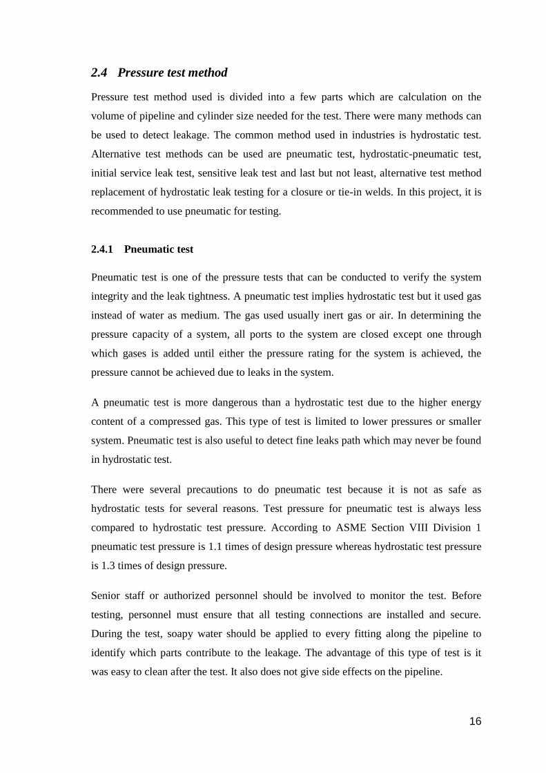
Type: Cap
Size: 1/4”
Connection: Swagelok tube fittings
Body Material: Aluminium
Figure 2-11: Swagelok Cap
Cap is usually liquid or gas tight, which covers the end of a pipe. A cap is used like
plug, except that the pipes cap screws or attaches on the male thread of a pipe. A cap
may have a solvent weld socket end or a female threaded end and the other end closed
off. In piping systems that use threads, the cap has female threads. Industrial caps can be
round, square, rectangular, U-shaped, I-shaped and may have a round hand grip or a flat
hand grip.
16
2.4 Pressure test method
Pressure test method used is divided into a few parts which are calculation on the
volume of pipeline and cylinder size needed for the test. There were many methods can
be used to detect leakage. The common method used in industries is hydrostatic test.
Alternative test methods can be used are pneumatic test, hydrostatic-pneumatic test,
initial service leak test, sensitive leak test and last but not least, alternative test method
replacement of hydrostatic leak testing for a closure or tie-in welds. In this project, it is
recommended to use pneumatic for testing.
2.4.1 Pneumatic test
Pneumatic test is one of the pressure tests that can be conducted to verify the system
integrity and the leak tightness. A pneumatic test implies hydrostatic test but it used gas
instead of water as medium. The gas used usually inert gas or air. In determining the
pressure capacity of a system, all ports to the system are closed except one through
which gases is added until either the pressure rating for the system is achieved, the
pressure cannot be achieved due to leaks in the system.
A pneumatic test is more dangerous than a hydrostatic test due to the higher energy
content of a compressed gas. This type of test is limited to lower pressures or smaller
system. Pneumatic test is also useful to detect fine leaks path which may never be found
in hydrostatic test.
There were several precautions to do pneumatic test because it is not as safe as
hydrostatic tests for several reasons. Test pressure for pneumatic test is always less
compared to hydrostatic test pressure. According to ASME Section VIII Division 1
pneumatic test pressure is 1.1 times of design pressure whereas hydrostatic test pressure
is 1.3 times of design pressure.
Senior staff or authorized personnel should be involved to monitor the test. Before
testing, personnel must ensure that all testing connections are installed and secure.
During the test, soapy water should be applied to every fitting along the pipeline to
identify which parts contribute to the leakage. The advantage of this type of test is it
was easy to clean after the test. It also does not give side effects on the pipeline.

17
2.4.2 Leak test solution
For leak detector solution, the Snoop liquid is suitable to use. Snoop liquid leak
detectors detect gas leaks in hard-to-reach areas. This snoop liquid can be obtained from
Swagelok. It has advantages in term of characteristic which are:
o Sustained bubble action works even on very small leaks and vertical surfaces.
o Flexible snooper tube extends for hard-to-reach areas.
o Noncorrosive, non-flammable formula does not contain chlorine.
o Contains corrosion inhibitor for added protection.
o Formula dries clean, without staining
It can be obtained in various sizes such as 59mL, 236 mL and 3.8 L (Swagelok web
catalogue).
2.4.3 Test Procedure (According to ASME B31.3)
a) Calculate test pressure at 1.1 x design pressure.
b) Pressurize test circuit with air or nitrogen to a gage pressure, which is the lesser
of one-half the test pressure or 25 psig.
c) Perform a preliminary check of all joints.
d) If no leaks are found, or all leaks are repaired, continue to increase pressure in
stages, allowing piping strains to equalize until the test pressure is reached.
e) Hold test pressure for 10 minutes then reduce to the design pressure.
f) Hold design pressure for 10 minutes or for a period of time required to examine
all joints and seals for leaks.
g) If leaks are found, release pressure, repair leaks and start again. If not, the
system is ready for service.
2.4.4 Safety precaution during conducting the test
While the test is in progress, all station personnel must be kept out of the testing area.
Personnel who are involved in testing must stand behind a barrier to ensure their safety,
and the testing area must be marked as a dangerous site. The section of pipeline being
tested must be supervised at all times during the test. Leakage or rupture during testing
can result in property damage or serious injury. All piping in the test section must be
restrained prior to testing so that no movement occurs. Before testing begins, personnel