industrial hydraulic valves - fluid power solutions valve industrial manifold and... · 2f1c.indd,...
TRANSCRIPT
Industrial Hydraulic Valves
Catalog HY14-2500/US
Directional Control, Pressure Control, Sandwich, Subplates & Manifolds, Accessories

Parker Hannifin CorporationHydraulic Valve DivisionElyria, Ohio, USA
Cat HY14-2500-frtcvr.indd, dd
II
Industrial Hydraulic ValvesCatalog HY14-2500/US
FAILURE OR IMPROPER SELECTION OR IMPROPER USE OF THE PRODUCTS DESCRIBED HEREIN OR RELATED ITEMS CAN CAUSE DEATH, PERSONAL INJURY AND PROPERTY DAMAGE.
• This document and other information from Parker-Hannifin Corporation, its subsidiaries and authorized distributors provide product or system options for further investigation by users having technical expertise.
• The user, through its own analysis and testing, is solely responsible for making the final selection of the system and components and assuring that all performance, endurance, maintenance, safety and warning requirements of the application are met. The user must analyze all aspects of the application, follow applicable industry standards, and follow the information concerning the product in the current product catalog and in any other materials provided from Parker or its subsidiaries or authorized distributors.
• To the extent that Parker or its subsidiaries or authorized distributors provide component or system options based upon data or specifications provided by the user, the user is responsible for determining that such data and specifications are suitable and sufficient for all applications and reasonably foreseeable uses of the components or systems.
WARNING – USER RESPONSIBILITY
The items described in this document are hereby offered for sale by Parker-Hannifin Corporation, its subsidiaries or its authorized distributors. This offer and its acceptance are governed by the provisions stated in the detailed “Offer of Sale” elsewhere in this document or available at www.parker.com/hydraulicvalve.
© Copyright 2011 Parker Hannifin Corporation, All Rights Reserved
OFFER OF SALE
For safety information, see Safety Guide SG HY14-1000 at www.parker.com/safety or call 1-800-CParker.
SAFETY GUIDE

2F1C.indd, dd
E1 Parker Hannifin CorporationHydraulic Valve DivisionElyria, Ohio, USA
Catalog HY14-2500/US Flow Control and Check Valves
E
Series 2F1C General Description ............................ 2-Way Flow Control Valves, Subplate Mounted ................................. E2 Operation ........................................................................................................................................................ E2 Features ......................................................................................................................................................... E2 Ordering Information ...................................................................................................................................... E2 Specifications ................................................................................................................................................. E3 Performance Curves ............................................................................................................................... E4 - E6 Dimensions ..................................................................................................................................................... E7
Series C4V General Description ............................ Direct Operated Check Valves, Subplate Mounted ............................ E8 Operation ........................................................................................................................................................ E8 Features ......................................................................................................................................................... E8 Ordering Information ...................................................................................................................................... E8 Specifications ................................................................................................................................................. E9 Performance Curves ....................................................................................................................................... E9 Dimensions ................................................................................................................................................... E10
Series C4V General Description ........................... Pilot Operated Check Valves, Subplate Mounted ............................ E12 Operation ...................................................................................................................................................... E12 Features ....................................................................................................................................................... E12 Ordering Information .................................................................................................................................... E12 Specifications ............................................................................................................................................... E13 Performance Curves ..................................................................................................................................... E13 Dimensions ................................................................................................................................................... E14
Series C5P General Description ............................ Pilot Operated Check Valves, SAE Flange ...................................... E15 Operation ...................................................................................................................................................... E15 Features ....................................................................................................................................................... E15 Ordering Information .................................................................................................................................... E15 Specifications ............................................................................................................................................... E16 Performance Curves ..................................................................................................................................... E16 Dimensions ................................................................................................................................................... E17
Series C5V General Description ............................ Direct Operated Check Valves, SAE Flange .................................... E18 Operation ...................................................................................................................................................... E18 Features ....................................................................................................................................................... E18 Ordering Information .................................................................................................................................... E18 Specifications ............................................................................................................................................... E19 Performance Curves ..................................................................................................................................... E19 Dimensions ................................................................................................................................................... E20
Terms of Sale and Warranty Limitations .......................................................................................................... E21
Safety Guide ...............................................................................................................................................E22 - E23
Contents

2F1C.indd, dd
E2 Parker Hannifin CorporationHydraulic Valve DivisionElyria, Ohio, USA
Pressure Compensated Flow Control ValvesCatalog HY14-2500/US
Series 2F1C
E
General Description
Series 2F1C 2-way flow control valves provide pres-sure and viscosity compensated flow from port A to port B. The counter direction is blocked (standard) or can be open via an integral reverse flow check valve (optional).
Operation
The compensator spool is located in front of the meter-ing spool. The metering spool is closed in the neutral position to avoid undesired initial actuator motion. The oil flow to open the metering spool has to pass a needle valve (not shown in the sectional drawing). The needle valve can be adjusted from the front panel to set the response time of the 2F1C.
The metering spool is adjusted by the main control knob. The key lock has three positions:
Lock: Adjustment is locked.
Adjust: Full adjustment is permitted.
Trim: Fine adjustment of ±5% is possible.
Features• 2 way flow control valve.
• Subplate mounting according to ISO 6263.
• Excellent fine adjustment.
• Adjustable response time.
• Closed in neutral position.
• Optional reverse flow check valve.
• 2 sizes: NG10 (3/8"), NG16 (3/4").
Technical Information
Weight:
2F1C02 6.0 kg (13.2 lbs.)
2F1C03 9.0 kg (19.8 lbs.)
2-Way Flow Control Valve
Size Adjustment Knob with
Lock
Design Series
Options Check with
Factory
2F1C
Code Description 02 NG10 (3/8")
03 NG16 (3/4")
Code Description 0 Without Check
C With Check
Seal
01 B
Fluorocarbon
Reverse Flow Check
5
Ordering Information

2F1C.indd, dd
E3 Parker Hannifin CorporationHydraulic Valve DivisionElyria, Ohio, USA
Pressure Compensated Flow Control ValvesCatalog HY14-2500/US
Series 2F1C
E
Size NG10 NG16
Actuator Manual flow rate adjustment
Mounting Type ISO 6263
Mounting Position Unrestricted
Fluid Temperature +70°C (+158°F) Maximum
Ambient Temprature -25°C to +50°C (-13°F to +122°F)
Viscosity Range 2.8 to 400 cSt / mm2/s (13 to 1854 SSU)
Filtration ISO 4406 (1999); 18/16/13 (meet NAS 1638:7
Maximum Pressure Difference See Diagram
Maximum Operating Pressure
Port A
Port B
2F1C02 14 - 280 Bar (203 - 4060 PSI)
0 - 270 Bar (0 - 3915 PSI)
2F1C03 14 - 350 Bar (203 - 5075 PSI)
0 - 340 Bar (0 - 4930 PSI)
Flow Direction A–B
B–A
Flow control function
Blocked or free flow through check valve
Specifications
2F1C.indd, dd
E4 Parker Hannifin CorporationHydraulic Valve DivisionElyria, Ohio, USA
Pressure Compensated Flow Control ValvesCatalog HY14-2500/US
Series 2F1C
E
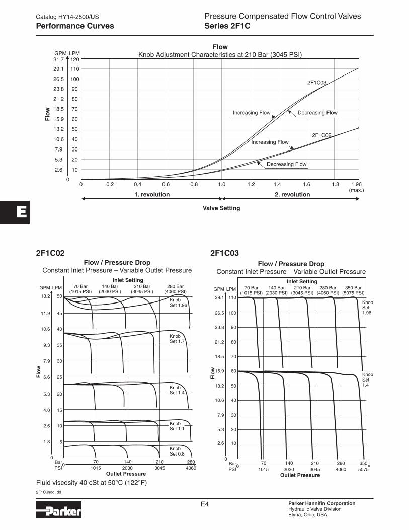
Performance Curves
2F1C02 2F1C03
Fluid viscosity 40 cSt at 50°C (122°F)
2F1C.indd, dd
E5 Parker Hannifin CorporationHydraulic Valve DivisionElyria, Ohio, USA
Pressure Compensated Flow Control ValvesCatalog HY14-2500/US
Series 2F1C
E
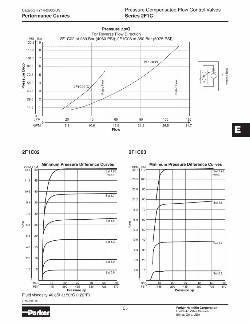
2F1C02 2F1C03
Performance Curves
Fluid viscosity 40 cSt at 50°C (122°F)

2F1C.indd, dd
E6 Parker Hannifin CorporationHydraulic Valve DivisionElyria, Ohio, USA
Pressure Compensated Flow Control ValvesCatalog HY14-2500/US
Series 2F1C
E2F1C02 2F1C03
Performance Curves
Fluid viscosity 40 cSt at 50°C (122°F)

2F1C.indd, dd
E7 Parker Hannifin CorporationHydraulic Valve DivisionElyria, Ohio, USA
Pressure Compensated Flow Control ValvesCatalog HY14-2500/US
Series 2F1C
E
Inch equivalents for millimeter dimensions are shown in (**)
Size ISO-code x1 x2 x3 x4 x5 x6 y1 y2 y3 y4 y5
02 6263-AM-07-2-A76.2
(3.00)79.4
(3.13)9.5
(0.37)44.5
(1.75)19.0
(0.75)–
82.5 (3.25)
23.8 (0.94)
30.2 (1.19)
41.3 (1.63)
39.7 (1.56)
03 6263-AK-06-2-A101.6 (4.00)
103.2 (4.06)
20.6 (0.81)
52.4 (2.06)
31.8 (1.25)
0.8 (0.03)
101.6 (4.00)
28.6 (1.13)
15.1 (0.59)
75.4 (2.97)
26.2 (1.03)
Size ISO-code B1 B2 H1 H2 H3 L1 L2 d1 d2 d3 d4
02 6263-AM-07-2-A101.6 (4.00)
38.1 (1.50)
119.6 (4.71)
87.4 (3.44)
6.4 (0.25)
95.2 (3.75)
47.6 (1.87)
6.4 (0.25)
57.2 (2.25)
8.7 (0.34)
14.2 (0.56)
03 6263-AK-06-2-A123.8 (4.87)
42.9 (1.69)
121.4 (4.78)
89.2 (3.51)
6.4 (0.25)
123.8 (4.87)
61.9 (2.44)
9.5 (0.37)
57.2 (2.25)
10.5 (0.41)
22.4 (0.88)
Size ISO-Code Bolt Kit DIN912 12.9 Surface Finish
02 6263-AM-07-2-A BK-700-70842-8 4xM8x100 31.8 Nm (23.5 lb.-ft.) ±15%S26-98617-5
03 6263-AK-06-2-A BK395 4xM10x100 63 Nm (46.5 lb.-ft.) ±15%
Dimensions
FluorocarbonSeal
Valve Subplate Size
2F1C02 518-00115-0 3/8" NPT Side Ported
2F1C03 518-00118-0 1/2" NPT Side Ported
C4V-DO.indd, dd
E8 Parker Hannifin CorporationHydraulic Valve DivisionElyria, Ohio, USA
Check ValvesCatalog HY14-2500/US
Series C4V (Direct Operated)
E
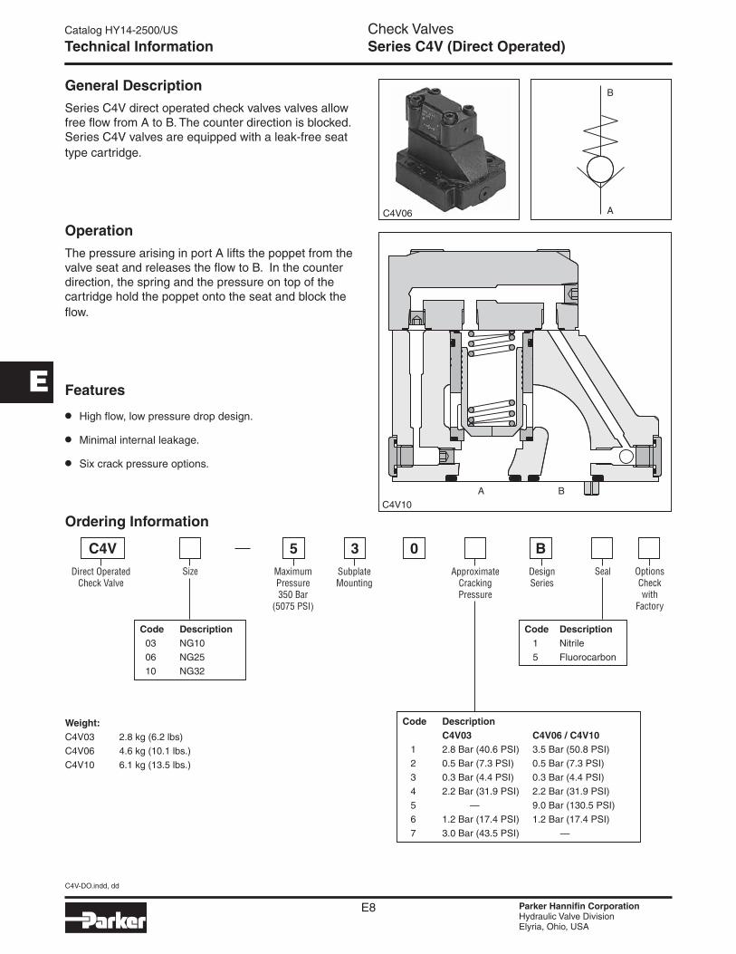
General Description
Series C4V direct operated check valves valves allow free flow from A to B. The counter direction is blocked. Series C4V valves are equipped with a leak-free seat type cartridge.
Operation
The pressure arising in port A lifts the poppet from the valve seat and releases the flow to B. In the counter direction, the spring and the pressure on top of the cartridge hold the poppet onto the seat and block the flow.
Features
• High flow, low pressure drop design.
• Minimal internal leakage.
• Six crack pressure options.
C4V10
C4V06
Technical Information
Direct Operated Check Valve
Design Series
BC4V
Ordering Information
Size
Code Description 03 NG10
06 NG25
10 NG32
Maximum Pressure 350 Bar
(5075 PSI)
5
Code Description C4V03 C4V06 / C4V10 1 2.8 Bar (40.6 PSI) 3.5 Bar (50.8 PSI)
2 0.5 Bar (7.3 PSI) 0.5 Bar (7.3 PSI)
3 0.3 Bar (4.4 PSI) 0.3 Bar (4.4 PSI)
4 2.2 Bar (31.9 PSI) 2.2 Bar (31.9 PSI)
5 — 9.0 Bar (130.5 PSI)
6 1.2 Bar (17.4 PSI) 1.2 Bar (17.4 PSI)
7 3.0 Bar (43.5 PSI) —
Seal
Code Description 1 Nitrile
5 Fluorocarbon
Weight:C4V03 2.8 kg (6.2 lbs)
C4V06 4.6 kg (10.1 lbs.)
C4V10 6.1 kg (13.5 lbs.)
Subplate Mounting
3Approximate
Cracking Pressure
0Options Check with
Factory

C4V-DO.indd, dd
E9 Parker Hannifin CorporationHydraulic Valve DivisionElyria, Ohio, USA
Check ValvesCatalog HY14-2500/US
Series C4V (Direct Operated)
E
SpecificationsGeneral
Size NG10 NG25 NG32
Subplate Mounting ISO 5781
Mounting Position Unrestricted
Ambient Temperature Range -20°C to +80°C (-4°F to +176°F)
Hydraulic
Maximum Operating Pressure 350 Bar (5075 PSI)
Pressure Range 105 Bar (1523 PSI), 210 Bar (3045 PSI), 350 Bar (5075 PSI)
Nominal Flow 150 LPM (39.7 GPM)
270 LPM (71.4 GPM)
450 LPM (119.0 GPM)
Fluid Hydraulic oil to DIN 51524
Viscosity Recommended Permitted
30 to 50 cSt / mm2/s (139 to 232 SSU) 20 to 380 cSt / mm2/s (93 to 1761 SSU)
Fluid Temperature Recommended Permitted
+30°C to +50°C (86°F to +122°F) -20°C to +70°C (-4°F to +158°F)
Filtration ISO Class 4406 (1999) 18/16/13 (meet NAS 1638:7)
Technical Information
Performance Curve
C4V-DO.indd, dd
E10 Parker Hannifin CorporationHydraulic Valve DivisionElyria, Ohio, USA
Check ValvesCatalog HY14-2500/US
E
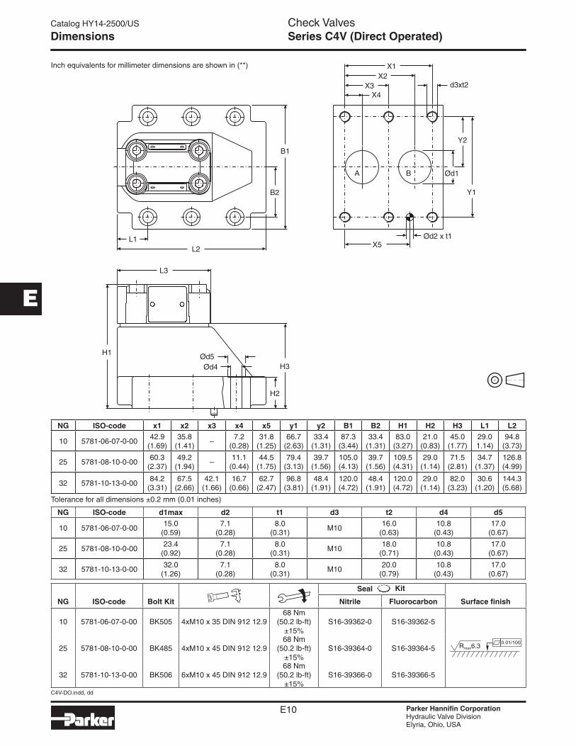
Inch equivalents for millimeter dimensions are shown in (**)
Dimensions Series C4V (Direct Operated)
Tolerance for all dimensions ±0.2 mm (0.01 inches)
NG ISO-code x1 x2 x3 x4 x5 y1 y2 B1 B2 H1 H2 H3 L1 L2
10 5781-06-07-0-0042.9
(1.69)35.8
(1.41)–
7.2(0.28)
31.8(1.25)
66.7(2.63)
33.4(1.31)
87.3(3.44)
33.4(1.31)
83.0(3.27)
21.0(0.83)
45.0(1.77)
29.01.14)
94.8(3.73)
25 5781-08-10-0-0060.3
(2.37)49.2
(1.94)–
11.1(0.44)
44.5(1.75)
79.4(3.13)
39.7(1.56)
105.0(4.13)
39.7(1.56)
109.5(4.31)
29.0(1.14)
71.5(2.81)
34.7(1.37)
126.8(4.99)
32 5781-10-13-0-0084.2
(3.31)67.5
(2.66)42.1
(1.66)16.7
(0.66)62.7
(2.47)96.8
(3.81)48.4
(1.91)120.0(4.72)
48.4(1.91)
120.0(4.72)
29.0(1.14)
82.0(3.23)
30.6(1.20)
144.3(5.68)
NG ISO-code d1max d2 t1 d3 t2 d4 d5
10 5781-06-07-0-0015.0
(0.59)7.1
(0.28)8.0
(0.31)M10
16.0(0.63)
10.8(0.43)
17.0(0.67)
25 5781-08-10-0-0023.4
(0.92)7.1
(0.28)8.0
(0.31)M10
18.0(0.71)
10.8(0.43)
17.0(0.67)
32 5781-10-13-0-0032.0
(1.26)7.1
(0.28)8.0
(0.31)M10
20.0(0.79)
10.8(0.43)
17.0(0.67)
NG ISO-code Bolt Kit Nitrile Fluorocarbon Surface finish
10 5781-06-07-0-00 BK505 4xM10 x 35 DIN 912 12.968 Nm
(50.2 lb-ft) ±15%
S16-39362-0 S16-39362-5
25 5781-08-10-0-00 BK485 4xM10 x 45 DIN 912 12.968 Nm
(50.2 lb-ft) ±15%
S16-39364-0 S16-39364-5
32 5781-10-13-0-00 BK506 6xM10 x 45 DIN 912 12.968 Nm
(50.2 lb-ft) ±15%
S16-39366-0 S16-39366-5
Seal

C4V-PO.indd, dd
E12 Parker Hannifin CorporationHydraulic Valve DivisionElyria, Ohio, USA
Check ValvesCatalog HY14-2500/US
Series C4V (Pilot Operated)
E
General DescriptionSeries C4V hydraulically pilot operated check valves allow free flow from A to B. The counter-flow direction is blocked.
When pressure is applied to control port X, the ring chamber flow from B to A is released.
Up to four different pilot control ratios are available (see Ordering Information).
Check valves allow free flow from A to B. The counter direction is blocked. The C4V series are equipped with a leak-free seat type cartridge.
OperationWhen no pressure is applied to the X-port, the flow from B to A is blocked, because the pressure in B is also in effect on top of the poppet.
Pressurizing the X port relieves the area on top of the poppet to the drain port and allows flow from B to A.
The seat design of the C4V valve series provides leak-free separation of port A and B in the closed position.
Features
• High flow, low pressure drop design.
• Minimal internal leakage.
must be connected to tank
Technical Information
Ordering Information
Code Description 1 1:1
3 3:1
8 8:1
9 10:1
Pilot Operated Check Valve
Design Series
BC4VSize
Code Description 03 NG10
06 NG25
10 NG32
Maximum Pressure 350 Bar
(5075 PSI)
5
Code Description Flow A to B Flow A to B C4V03 C4V06 / C4V10 2 1.0 Bar (14.5 PSI) 1.0 Bar (14.5 PSI)
4 4.0 Bar (58.0 PSI) 3.5 Bar (50.8 PSI)
6 2.0 Bar (29.0 PSI) 2.2 Bar (31.9 PSI)
Flow B to A Flow B to A C4V03 C4V06 / C4V10 2 1.5 Bar (21.8 PSI) 1.7 Bar (24.7 PSI)
4 5.5 Bar (79.8 PSI) 6.0 Bar (87.0 PSI)
6 3.0 Bar (43.5 PSI) 3.8 Bar (55.1 PSI)
Seal
Code Description 1 Nitrile
5 Fluorocarbon
Weight:C4V03 2.8 kg (6.2 lbs)
C4V06 4.6 kg (10.1 lbs.)
C4V10 6.1 kg (13.5 lbs.)
Y1 Port G1/4"
9Approximate
Cracking Pressure
Opening Ratio
Options Check with
Factory

C4V-PO.indd, dd
E13 Parker Hannifin CorporationHydraulic Valve DivisionElyria, Ohio, USA
Check ValvesCatalog HY14-2500/US
Series C4V (Pilot Operated)
E
Technical Information
Performance Curve
SpecificationsGeneral
Size NG10 NG25 NG32
Subplate Mounting ISO 5781
Mounting Position Unrestricted
Ambient Temperature Range -20°C to +80°C (-4°F to +176°F)
Hydraulic
Maximum Operating Pressure 350 Bar (5075 PSI)
Nominal Flow 150 LPM (39.7 GPM) 270 LPM (71.4 GPM) 450 LPM (119.0 GPM)
Fluid Hydraulic oil to DIN 51524
Viscosity Recommended Permitted
30 to 50 cSt / mm2/s (139 to 232 SSU) 20 to 380 cSt / mm2/s (93 to 1761 SSU)
Fluid Temperature Recommended Permitted
+30C° to +50°C (86°F to +122°F) -20°C to +70°C (-4°F to +158°F)
Filtration ISO Class 4406 (1999) 18/16/13 (meet NAS 1638:7)

C4V-PO.indd, dd
E14 Parker Hannifin CorporationHydraulic Valve DivisionElyria, Ohio, USA
Check ValvesCatalog HY14-2500/US
Series C4V (Pilot Operated)
E
Inch equivalents for millimeter dimensions are shown in (**)
Dimensions
Tolerance for all dimensions ±0.2 mm (0.01 inches)
NG ISO-code B1 B2 H1 H2 H3 H4 H5 H6 L1 L2 L3 L4 L5 L6
10 5781-06-07-0-0087.3
(3.44)33.4
(1.31)83.0
(3.27)21.0
(0.83)62.5
(2.46)– – –
29.4(1.16)
95.2(3.75)
43.7(1.72)
111.0(4.37)
5.0(0.20)
–
25 5781-08-10-0-00105
(4.13)39.7
(1.56)109.5(4.31)
29.0(1.14)
89.0(3.50)
– – –35.1
(1.38)127.2(5.01)
43.7(1.72)
111.0(4.37)
5.0(0.20)
–
32 5781-10-13-0-00120
(4.72)48.4
(1.91)120.0(4.72)
29.0(1.14)
99.5(3.92)
– – –31.0
(1.22)144.7(5.70)
43.7(1.72)
111.0(4.37)
5.0(0.20)
–
NG ISO-code d1max d2max d3 t3 d4 t4 d5 d6
10 5781-06-07-0-0015.0
(0.59)7.0
(0.28)7.1
(0.28)8.0
(0.31)M10
16.0(0.63)
10.8(0.43)
17.0(0.67)
25 5781-08-10-0-0023.4
(0.92)7.1
(0.28)7.1
(0.28)8.0
(0.31)M10
18.0(0.71)
10.8(0.43)
17.0(0.67)
32 5781-10-13-0-0032.0
(1.26)7.1
(0.28)7.1
(0.28)8.0
(0.31)M10
20.0(0.79)
10.8(0.43)
17.0(0.67)
NG ISO-code x1 x2 x3 x4 x5 x6 x7 y1 y2 y3 y4 y5 y6
10 5781-06-07-0-0042.9
(1.69)35.8
(1.41)– –
7.2(0.28)
21.5(0.85)
31.8(1.25)
66.7(2.63)
58.8(2.31)
33.4(1.31)
– – –
25 5781-08-10-0-0060.3
(2.37)49.2
(1.94)– –
11.1(0.44)
20.6(0.81)
44.5(1.75)
79.4(3.13)
73.0(2.87)
39.7(1.56)
– – –
32 5781-10-13-0-0084.2
(3.31)67.5
(2.66)–
42.1(1.66)
16.7(0.66)
24.6(0.97)
62.7(2.47)
96.8(3.81)
92.8(3.65)
48.4(1.91)
– – –
NG ISO-code Bolt Kit Nitrile Fluorocarbon Surface finish
10 5781-06-07-0-00 BK505 4xM10 x 35 DIN 912 12.968 Nm
(50.2 lb-ft) ±15%
S16-39362-0 S16-39362-5
25 5781-08-10-0-00 BK485 4xM10 x 45 DIN 912 12.968 Nm
(50.2 lb-ft) ±15%
S16-39364-0 S16-39364-5
32 5781-10-13-0-00 BK506 6xM10 x 45 DIN 912 12.968 Nm
(50.2 lb-ft) ±15%
S16-39366-0 SS16-39366-5
Seal
NG ISO-code Subplate Size
10 5781-06-07-0-00 SPP3M6B910 A, B = 3/4" BSPP x, y = 1/4" BSPP
25 5781-08-10-0-00 SPP6M8B910 A, B = 1" BSPP x, y = 1/4" BSPP
32 5781-10-13-0-00 SPP10M12B910 A, B = 1 1/2" BSPP x, y = 1/4" BSPP
C5P.indd, dd
E15 Parker Hannifin CorporationHydraulic Valve DivisionElyria, Ohio, USA
Check ValvesCatalog HY14-2500/US
Series C5P (Pilot Operated)
E
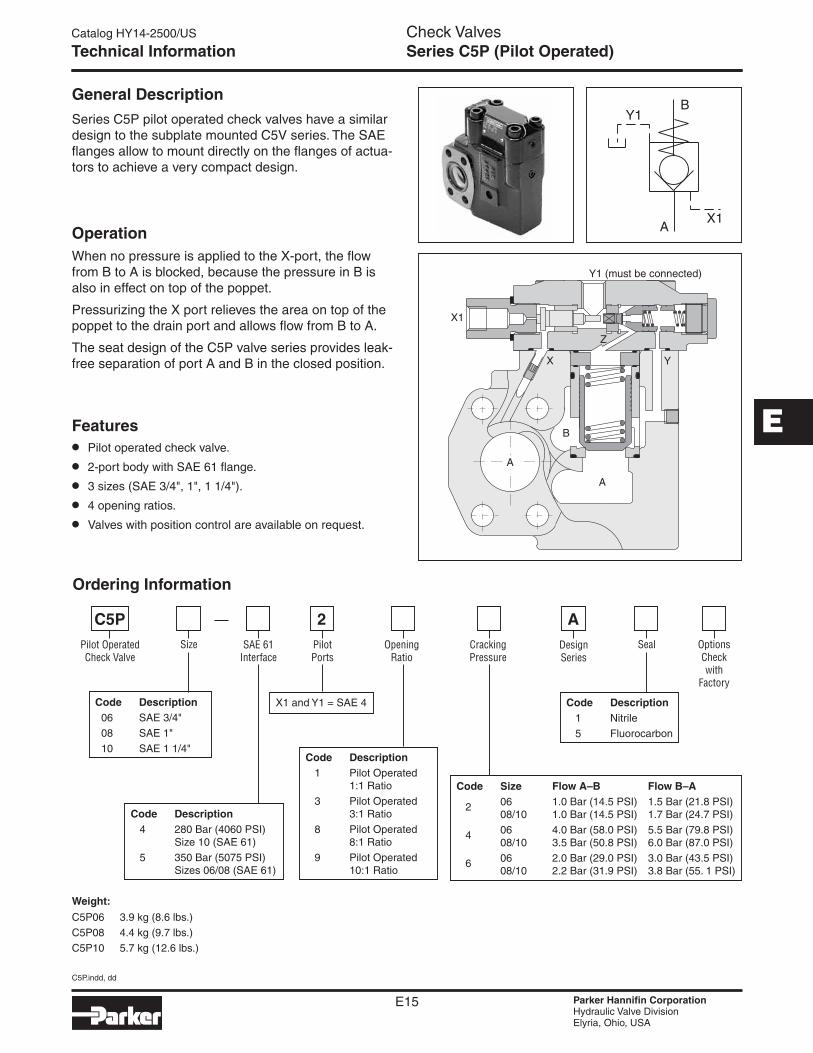
General Description
Series C5P pilot operated check valves have a similar design to the subplate mounted C5V series. The SAE flanges allow to mount directly on the flanges of actua-tors to achieve a very compact design.
OperationWhen no pressure is applied to the X-port, the flow from B to A is blocked, because the pressure in B is also in effect on top of the poppet.
Pressurizing the X port relieves the area on top of the poppet to the drain port and allows flow from B to A.
The seat design of the C5P valve series provides leak-free separation of port A and B in the closed position.
Features• Pilot operated check valve.
• 2-port body with SAE 61 flange.
• 3 sizes (SAE 3/4", 1", 1 1/4").
• 4 opening ratios.
• Valves with position control are available on request.
Technical Information
Weight:
C5P06 3.9 kg (8.6 lbs.)
C5P08 4.4 kg (9.7 lbs.)
C5P10 5.7 kg (12.6 lbs.)
Pilot Operated Check Valve
Size SAE 61 Interface
Pilot Ports
Options Check with
Factory
C5P
Code Description 06 SAE 3/4"
08 SAE 1"
10 SAE 1 1/4"
Code Description 4 280 Bar (4060 PSI) Size 10 (SAE 61)
5 350 Bar (5075 PSI) Sizes 06/08 (SAE 61)
Opening Ratio
Code Description 1 Nitrile
5 Fluorocarbon
SealDesign Series
A
Code Description 1 Pilot Operated 1:1 Ratio
3 Pilot Operated 3:1 Ratio
8 Pilot Operated 8:1 Ratio
9 Pilot Operated 10:1 Ratio
2Cracking Pressure
Code Size Flow A–B Flow B–A 2 06 1.0 Bar (14.5 PSI) 1.5 Bar (21.8 PSI) 08/10 1.0 Bar (14.5 PSI) 1.7 Bar (24.7 PSI)
4 06 4.0 Bar (58.0 PSI) 5.5 Bar (79.8 PSI) 08/10 3.5 Bar (50.8 PSI) 6.0 Bar (87.0 PSI)
6 06 2.0 Bar (29.0 PSI) 3.0 Bar (43.5 PSI) 08/10 2.2 Bar (31.9 PSI) 3.8 Bar (55. 1 PSI)
X1 and Y1 = SAE 4
Ordering Information
C5P.indd, dd
E16 Parker Hannifin CorporationHydraulic Valve DivisionElyria, Ohio, USA
Check ValvesCatalog HY14-2500/US
Series C5P (Pilot Operated)
E
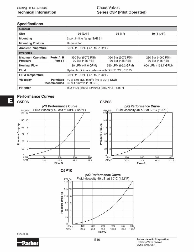
SpecificationsGeneral
Size 06 (3/4") 08 (1") 10 (1 1/4")
Mounting 2-port in-line flange SAE 61
Mounting Position Unrestricted
Ambient Temprature -20°C to +50°C (-4°F to +122°F)
Hydraulic
Maximum Operating Pressure
Ports A, B Port Y1
350 Bar (5075 PSI) 30 Bar (435 PSI)
350 Bar (5075 PSI) 30 Bar (435 PSI)
280 Bar (4060 PSI) 30 Bar (435 PSI)
Nominal Flow 180 LPM (47.6 GPM) 360 LPM (95.2 GPM) 600 LPM (158.7 GPM)
Fluid Hydraulic oil in accordance with DIN 51524...51525
Fluid Temperature -20°C to +80°C (-4°F to +176°F)
Viscosity Permitted Recommended
10 to 650 cSt / mm2/s (46 to 3013 SSU) 30 cSt / mm2/s (139 SSU)
Filtration ISO 4406 (1999) 18/16/13 (acc. NAS 1638:7)
Technical Information
C5P06 C5P08
C5P10
Performance Curves
C5P.indd, dd
E17 Parker Hannifin CorporationHydraulic Valve DivisionElyria, Ohio, USA
Check ValvesCatalog HY14-2500/US
Series C5P (Pilot Operated)
E
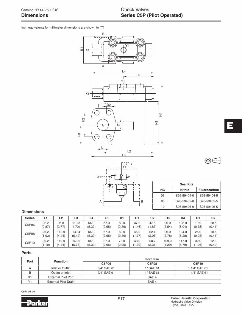
Inch equivalents for millimeter dimensions are shown in (**)
Dimensions
Ports
Series L1 L2 L3 L4 L5 B1 H1 H2 H3 H4 D1 D2
C5P0622.2
(0.87)95.8
(3.77)119.8 4.72)
137.0 (5.39)
67.3 (2.65)
60.0 (2.36)
37.0 (1.46)
47.6 (1.87)
90.0 (3.54)
128.0 (5.04)
19.0 (0.75)
10.5 (0.41)
C5P0826.2
(1.03)112.9 (4.44)
139.4 (5.49)
137.0 (5.39)
67.3 (2.65)
60.0 (2.36)
45.0 (1.77)
52.4 (2.06)
96.0 (3.78)
134.0 (5.28)
25.0 (0.93)
10.5 (0.41)
C5P1030.2
(1.19)112.9 (4.44)
146.9 (5.78)
137.0 (5.39)
67.3 (2.65)
75.0 (2.95)
48.0 (1.39)
58.7 (2.31)
109.0 (4.29)
147.0 (5.79)
32.0 (1.26)
12.5 (0.49)
Port FunctionPort Size
C5P06 C5P08 C5P10A Inlet or Outlet 3/4" SAE 61 1" SAE 61 1 1/4" SAE 61B Outlet or Inlet 3/4" SAE 61 1" SAE 61 1 1/4" SAE 61
X1 External Pilot Port SAE 4Y1 External Pilot Drain SAE 4
Dimensions
Seal Kits
NG Nitrile Fluorocarbon
06 S26-59404-0 S26-59404-5
08 S26-59405-0 S26-59405-5
10 S26-59406-0 S26-59406-5

C5V.indd, dd
E18 Parker Hannifin CorporationHydraulic Valve DivisionElyria, Ohio, USA
Check ValvesCatalog HY14-2500/US
E
Series C5V (Direct Operated)
General Description
Series C5V direct operated check valves provide free flow in one direction and block the flow in the counter direction.
The SAE flanges allow to mount the C5V directly on the pressure port of pumps for protection against pres-sure shocks from the system.
Operation
The ball is held on its seat by a spring under zero pres-sure condition. When flow is increased to the cracking pressure, free flow is allowed from port A to port B. Blocked flow is created when operating pressure and spring on Port B exceed pressure on port A.
Features• Direct operated check valve.
• SAE 61 and SAE 62 flanges.
• 4 sizes (SAE 3/4", 1", 1 1/4", 1 1/2").
• 3 springs.
• 2 different seal configurations.
Technical Information
Code Description 1 Nitrile
5 Fluorocarbon
Code Description Omit Standard
019* C5V10 for M14 Mounting Screws
Direct Operated Check Valve
Size Flange Body Sealing
Seal Options
C5V
Design Series
Code Description 06 SAE 3/4"
08 SAE 1"
10 SAE 1 1/4"
12 SAE 1 1/2"
Code Description 3 SAE 61
6 SAE 62
Cracking Pressure
B
Code Description 0 0.5 Bar (7 PSI)
1 1.0 Bar (15 PSI)
2 2.0 Bar (29 PSI)
Code Description 1 Sealing for Port A
2* Sealing for Ports A and X
3 Without Sealing
* For combination with R5U Unloading Valve (SAE 61 only).
* For SAE 62 only.
Weight:
C5V06 0.6 kg (1.3 lbs.)
C5V08 0.9 kg (2.0 lbs.)
C5V10 1.3 kg (2.9 lbs.)
C5V12 1.8 kg (4.0 lbs.)
Ordering Information

C5V.indd, dd
E19 Parker Hannifin CorporationHydraulic Valve DivisionElyria, Ohio, USA
Check ValvesCatalog HY14-2500/US
E
Series C5V (Direct Operated)
SpecificationsGeneral
Size 06 (3/4") 08 (1") 10 (1 1/4") 12 (1 1/2")
Mounting 2-port in-line flange SAE 61 and SAE 62
Mounting Position Unrestricted
Ambient Temprature -20°C to +50°C (-4°F to +122°F)
Hydraulic
Maximum Operating Pressure
SAE 61 SAE 62
350 Bar (5075 PSI) 420 Bar (6090 PSI)
350 Bar (5075 PSI) 420 Bar (6090 PSI)
280 Bar (4060 PSI) 420 Bar (6090 PSI)
210 Bar (3045 PSI) 420 Bar (6090 PSI)
Nominal Flow 100 LPM (26.5 GPM) 200 LPM (52.9 GPM) 400 LPM (105.8 GPM) 750 LPM (198.4 GPM)
Fluid Hydraulic oil in accordance with DIN 51524...51525
Fluid Temperature -20°C to +80°C (-4°F to +176°F)
Viscosity Permitted Recommended
10 to 650 cSt / mm2/s (46 to 3013 SSU) 30 cSt / mm2/s (139 SSU)
Filtration ISO 4406 (1999) 18/16/13 (acc. NAS 1638:7)
Technical Information
C5V06
C5V10 C5V12
C5V08
Performance Curves

C5V.indd, dd
E20 Parker Hannifin CorporationHydraulic Valve DivisionElyria, Ohio, USA
Check ValvesCatalog HY14-2500/US
E
Series C5V (Direct Operated)
Inch equivalents for millimeter dimensions are shown in (**)
Series Nominal Size L1 L2 L3 H1 H2 H3 B1 D1 D2 D3 + 0.8 D4
C5V06 3/4"
SAE 6148.0
(1.89)22.2
(0.87)27.2
(1.07)64.0
(2.52)47.6
(1.87)22.4
(0.88)45.0
(1.77)10.5
(0.41)Ø3.0 (0.12)
19.0 (0.75)
19.0 (0.75)
SAE 6248.0
(1.89)23.8
(0.94)27.2
(1.07)64.0
(2.52)50.8
(2.00)22.4
(0.88)45.0
(1.77)10.5
(0.41)–
19.0 (0.75)
19.0 (0.75)
C5V08 1"SAE 61
60.0 (2.36)
26.2 (1.03)
27.2 (1.07)
74.0 (2.91)
52.4 (2.06)
22.4 (0.88)
45.0 (1.77)
10.5 (0.41)
Ø3.0 (0.12)
25.0 (0.98)
25.0 (0.98)
SAE 6260.0
(2.36)27.8
(1.09)27.2
(1.07)74.0
(2.91)57.2
(2.25)22.4
(0.88)45.0
(1.77)12.5
(0.49)–
25.0 (0.98)
25.0 (0.98)
C5V10 1 1/4"SAE 61
68.0 (2.68)
30.2 (1.19)
27.2 (1.07)
85.0 (3.35)
58.7 (2.31)
22.4 (0.88)
50.0 (1.97)
12.5 (0.49)
Ø3.0 (0.12)
32.0 (1.26)
32.0 (1.26)
SAE 6268.0
(2.68)31.8
(1.25)27.2
(1.07)85.0
(3.35)66.7
(2.63)22.4
(0.88)50.0
(1.97)13.5* (0.53)
–32.0
(1.26)32.0
(1.26)
C5V12 1 1/2"SAE 61
80.0(3.15)
35.7 (1.41)
27.2 (1.07)
104.0 (4.09)
69.8 (2.75)
22.4 (0.88)
50.0 (1.97)
13.5 (0.53)
Ø3.0 (0.12)
42.0 (1.65)
38.0 (1.50)
SAE 6280.0
(3.15)36.5
(1.44)27.2
(1.07)104.0 (4.09)
79.4 (3.13)
22.4 (0.88)
50.0 (1.97)
17.0 (0.67)
–42.0
(1.65)38.0
(1.50)
* D1 = 15 (0.59) at option code 019 for M14 mounting screws.
Dimensions
Seal Kits
NG Nitrile Fluorocarbon
3 S26-75409-0 S26-75409-5
6 S26-75410-0 S26-75410-5
10 S26-75411-0 S26-75411-5
12 S26-75412-0 S26-75412-5

C5V.indd, dd
E18 Parker Hannifin CorporationHydraulic Valve DivisionElyria, Ohio, USA
Check ValvesCatalog HY14-2500/US
E
Series C5V (Direct Operated)
General Description
Series C5V direct operated check valves provide free flow in one direction and block the flow in the counter direction.
The SAE flanges allow to mount the C5V directly on the pressure port of pumps for protection against pres-sure shocks from the system.
Operation
The ball is held on its seat by a spring under zero pres-sure condition. When flow is increased to the cracking pressure, free flow is allowed from port A to port B. Blocked flow is created when operating pressure and spring on Port B exceed pressure on port A.
Features• Direct operated check valve.
• SAE 61 and SAE 62 flanges.
• 4 sizes (SAE 3/4", 1", 1 1/4", 1 1/2").
• 3 springs.
• 2 different seal configurations.
Technical Information
Code Description 1 Nitrile
5 Fluorocarbon
Code Description Omit Standard
019* C5V10 for M14 Mounting Screws
Direct Operated Check Valve
Size Flange Body Sealing
Seal Options
C5V
Design Series
Code Description 06 SAE 3/4"
08 SAE 1"
10 SAE 1 1/4"
12 SAE 1 1/2"
Code Description 3 SAE 61
6 SAE 62
Cracking Pressure
B
Code Description 0 0.5 Bar (7 PSI)
1 1.0 Bar (15 PSI)
2 2.0 Bar (29 PSI)
Code Description 1 Sealing for Port A
2* Sealing for Ports A and X
3 Without Sealing
* For combination with R5U Unloading Valve (SAE 61 only).
* For SAE 62 only.
Weight:
C5V06 0.6 kg (1.3 lbs.)
C5V08 0.9 kg (2.0 lbs.)
C5V10 1.3 kg (2.9 lbs.)
C5V12 1.8 kg (4.0 lbs.)
Ordering Information

C5V.indd, dd
E19 Parker Hannifin CorporationHydraulic Valve DivisionElyria, Ohio, USA
Check ValvesCatalog HY14-2500/US
E
Series C5V (Direct Operated)
SpecificationsGeneral
Size 06 (3/4") 08 (1") 10 (1 1/4") 12 (1 1/2")
Mounting 2-port in-line flange SAE 61 and SAE 62
Mounting Position Unrestricted
Ambient Temprature -20°C to +50°C (-4°F to +122°F)
Hydraulic
Maximum Operating Pressure
SAE 61 SAE 62
350 Bar (5075 PSI) 420 Bar (6090 PSI)
350 Bar (5075 PSI) 420 Bar (6090 PSI)
280 Bar (4060 PSI) 420 Bar (6090 PSI)
210 Bar (3045 PSI) 420 Bar (6090 PSI)
Nominal Flow 100 LPM (26.5 GPM) 200 LPM (52.9 GPM) 400 LPM (105.8 GPM) 750 LPM (198.4 GPM)
Fluid Hydraulic oil in accordance with DIN 51524...51525
Fluid Temperature -20°C to +80°C (-4°F to +176°F)
Viscosity Permitted Recommended
10 to 650 cSt / mm2/s (46 to 3013 SSU) 30 cSt / mm2/s (139 SSU)
Filtration ISO 4406 (1999) 18/16/13 (acc. NAS 1638:7)
Technical Information
C5V06
C5V10 C5V12
C5V08
Performance Curves

C5V.indd, dd
E20 Parker Hannifin CorporationHydraulic Valve DivisionElyria, Ohio, USA
Check ValvesCatalog HY14-2500/US
E
Series C5V (Direct Operated)
Inch equivalents for millimeter dimensions are shown in (**)
Series Nominal Size L1 L2 L3 H1 H2 H3 B1 D1 D2 D3 + 0.8 D4
C5V06 3/4"
SAE 6148.0
(1.89)22.2
(0.87)27.2
(1.07)64.0
(2.52)47.6
(1.87)22.4
(0.88)45.0
(1.77)10.5
(0.41)Ø3.0 (0.12)
19.0 (0.75)
19.0 (0.75)
SAE 6248.0
(1.89)23.8
(0.94)27.2
(1.07)64.0
(2.52)50.8
(2.00)22.4
(0.88)45.0
(1.77)10.5
(0.41)–
19.0 (0.75)
19.0 (0.75)
C5V08 1"SAE 61
60.0 (2.36)
26.2 (1.03)
27.2 (1.07)
74.0 (2.91)
52.4 (2.06)
22.4 (0.88)
45.0 (1.77)
10.5 (0.41)
Ø3.0 (0.12)
25.0 (0.98)
25.0 (0.98)
SAE 6260.0
(2.36)27.8
(1.09)27.2
(1.07)74.0
(2.91)57.2
(2.25)22.4
(0.88)45.0
(1.77)12.5
(0.49)–
25.0 (0.98)
25.0 (0.98)
C5V10 1 1/4"SAE 61
68.0 (2.68)
30.2 (1.19)
27.2 (1.07)
85.0 (3.35)
58.7 (2.31)
22.4 (0.88)
50.0 (1.97)
12.5 (0.49)
Ø3.0 (0.12)
32.0 (1.26)
32.0 (1.26)
SAE 6268.0
(2.68)31.8
(1.25)27.2
(1.07)85.0
(3.35)66.7
(2.63)22.4
(0.88)50.0
(1.97)13.5* (0.53)
–32.0
(1.26)32.0
(1.26)
C5V12 1 1/2"SAE 61
80.0(3.15)
35.7 (1.41)
27.2 (1.07)
104.0 (4.09)
69.8 (2.75)
22.4 (0.88)
50.0 (1.97)
13.5 (0.53)
Ø3.0 (0.12)
42.0 (1.65)
38.0 (1.50)
SAE 6280.0
(3.15)36.5
(1.44)27.2
(1.07)104.0 (4.09)
79.4 (3.13)
22.4 (0.88)
50.0 (1.97)
17.0 (0.67)
–42.0
(1.65)38.0
(1.50)
* D1 = 15 (0.59) at option code 019 for M14 mounting screws.
Dimensions
Seal Kits
NG Nitrile Fluorocarbon
3 S26-75409-0 S26-75409-5
6 S26-75410-0 S26-75410-5
10 S26-75411-0 S26-75411-5
12 S26-75412-0 S26-75412-5