industrial winch · winching v.s. hoisting. a pulling winch should not be used for lifting. a...
TRANSCRIPT

Industrial Winch
Thank you for purchasing a Winch. This manual covers operation and maintenance of the winch. All information in this publication is based on the latest production information available at the time of printing. We reserve the right to make changes without notice because of continued productimprovement.
The winch has been designed to give safe and dependable service if operated according to the instructions. Please read and understand this manual before installation and operation of winch. Careless winch operation can result in serious injury or property damage.
When requesting information or ordering replacement parts, always give the following information: 1. Winch Model and Voltage 2. Serial Number 3. Item. No. and Part Number 4. Part Description
1. The winch is a very powerful machine. Treat with extreme care and observe all caution and warnings.2. The winch is rated at the first layer of wire rope on the drum for intermittent-periodic duty.3. The winch is not to be used to lift, support or otherwise transport personnel. 4. A minimum of five (5) wraps of rope around the drum is necessary to support the rated load.5. Keep clear of winch, rope, hook, and fairlead while operating.6. Wire rope can break without warning. Always keep a safe distance from the winch and rope while under a load.7. Failure to adequately align, support, or attach winch to a suitable mounting base could result in a loss of efficiency of performance or damage the winch, wire rope and mounting channel.
1
WARNING!
I . Safety Requirement
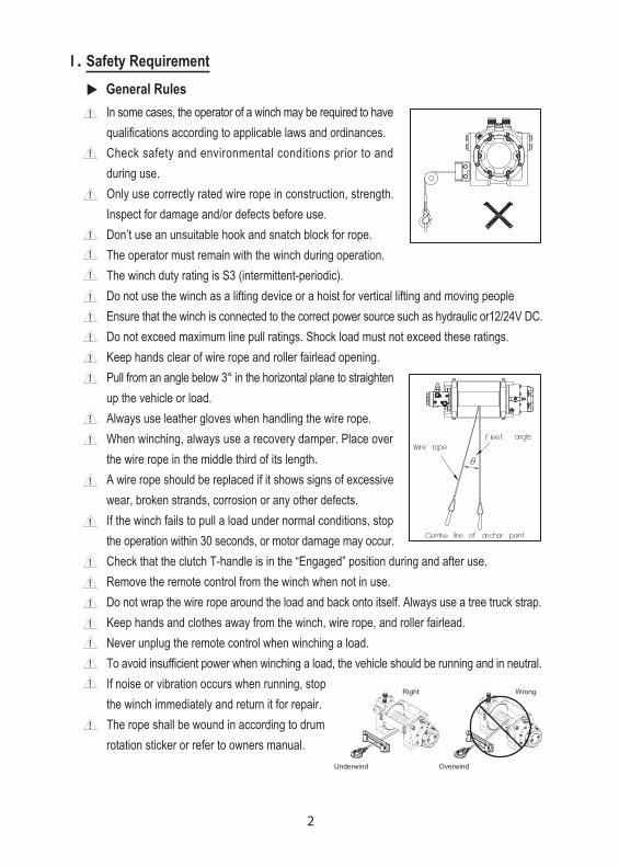
In some cases, the operator of a winch may be required to have qualifications according to applicable laws and ordinances.Check safety and environmental conditions prior to and during use.Only use correctly rated wire rope in construction, strength. Inspect for damage and/or defects before use.Don’t use an unsuitable hook and snatch block for rope.The operator must remain with the winch during operation.The winch duty rating is S3 (intermittent-periodic).Do not use the winch as a lifting device or a hoist for vertical lifting and moving people Ensure that the winch is connected to the correct power source such as hydraulic or12/24V DC. Do not exceed maximum line pull ratings. Shock load must not exceed these ratings.Keep hands clear of wire rope and roller fairlead opening.Pull from an angle below 3° in the horizontal plane to straighten up the vehicle or load.Always use leather gloves when handling the wire rope.When winching, always use a recovery damper. Place over the wire rope in the middle third of its length.A wire rope should be replaced if it shows signs of excessive wear, broken strands, corrosion or any other defects.If the winch fails to pull a load under normal conditions, stop the operation within 30 seconds, or motor damage may occur.Check that the clutch T-handle is in the “Engaged” position during and after use.Remove the remote control from the winch when not in use.Do not wrap the wire rope around the load and back onto itself. Always use a tree truck strap.Keep hands and clothes away from the winch, wire rope, and roller fairlead.Never unplug the remote control when winching a load.To avoid insufficient power when winching a load, the vehicle should be running and in neutral.If noise or vibration occurs when running, stop the winch immediately and return it for repair.The rope shall be wound in according to drum rotation sticker or refer to owners manual.
2
!
!
!
!
!
!
!
!
!
!
!
!
!
!
!
!
!
!
!
!
!
!
!
General Rules

I I . Hydraulic System Installation
3
(Powered by PTO / power take off unit driven pump)
Advantage: Professional winch system for “Working” applications, cost effective, extremely powerful, reliable, light weight and variable line speed for high work rate.
For HV winch
For Bison winch
4
Hydraulic Fluid ● The hydraulic fluid should be a high grade, petroleum based fluid, with rust, oxidation and wear resistance. Fluid cleanliness and operating viscosity are critical to winch reliability, efficiency and service lift.
Hydraulic Pump ● To maintain the maximum performance, the hydraulic pump must supply the maximum flow of hydraulic fluid at the hydraulic pressure stated in specification. ● With a max. oil supply mentioned on the instruction manual at top motor rpm and the pump must be capable of delivering the operation pressure mentioned on the instruction manual too.
Hydraulic Control Valve ● The control valve must have a four-way spring return to neutral feature, which provides for open flow from the pressure ports of the winch to the reservoir in neutral position of the control (motor spool).
Hydraulic Pressure Relief ● The hydraulic system requires a pressure relief set at the operating pressured. ● Failure to use the correct pressure and flow may result in damage to the winch, property or personal injury.
Hydraulic Reservoir ● The hydraulic reservoir has sufficient capacity to provide good heat dissipation in order to prevent over-heating of the hydraulic fluid. ● Must be fitted with an oil filler device comprising strainer and filter and a dip stick.The capacity of the tank should be at least 60 liters.
Over-Center Valve / Counterbalance Valve ● Give smoothly controlled winch out when under load and to provide full dynamic braking. It must be installed to hold full load. ● The Port A of over-center valve means the inlet port of oil from reservoir and the Port B meaning the return port of oil to reservoir. ● Over-center valve is a standard accessory for HV winch and counterbalance valve for Bison winch.
Hydraulic Hoses ● The following hydraulic hoses are recommended for maximum efficiency of the hydraulic winch. The bigger nominal bore hose, the better winch performance. ● All hose lengths are kept to a minimum because pressure and flow loss is increased as hose length increases. ● Pressure and return lines in excess of 3.5 meter (11.5”) should be compensated with an increase in nominal bore size. Motor drain line pipe shall be rated at1/4” BSP N.B. Inlet line ………….…... 1 1/4” – 1 1/2” nominal bore (N.B.) from reservoir to pump Return line …………… 1” (N.B.) from control to reservoir Pressure hoses …....... 1/2” (N.B.) from control valve to over-center valve Motor drain line pipe… 1/4” BSP N.B.
5
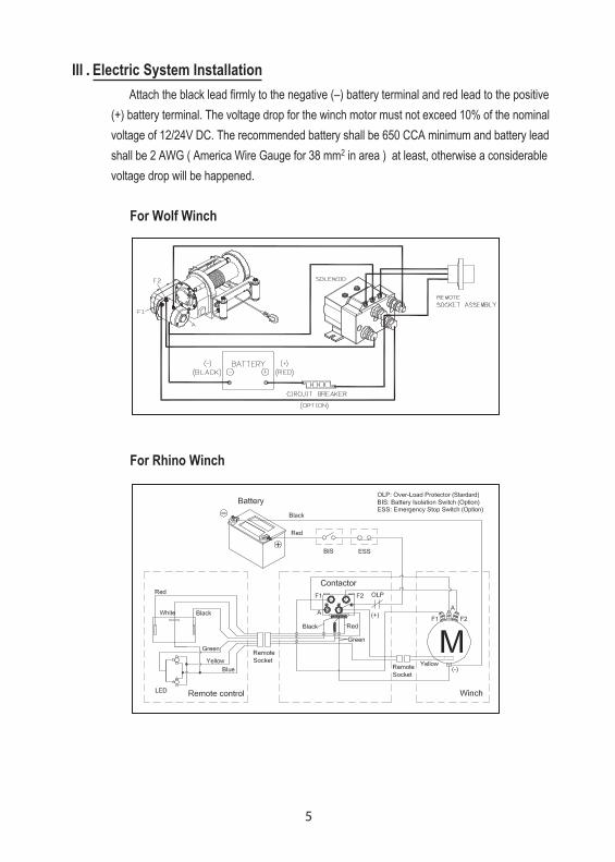
For Rhino Winch
III . Electric System Installation Attach the black lead firmly to the negative (–) battery terminal and red lead to the positive (+) battery terminal. The voltage drop for the winch motor must not exceed 10% of the nominal voltage of 12/24V DC. The recommended battery shall be 650 CCA minimum and battery lead shall be 2 AWG ( America Wire Gauge for 38 mm2 in area ) at least, otherwise a considerable voltage drop will be happened.
For Wolf Winch
6
Duty Cycle Ratings All industrial winches are rated at S3 10%ED & 1min/10min rating intermittent periodic duty.
IV . Winching PrinciplesCalculating Fleet Angle
To obtain the best wire rope service, the direction of pull will be on a horizontal within ±3 degrees and perpendicular to be centerline of the winch drum within ±3 degrees. If the fleet angle is bigger than the recommended angles, a good spooling cannot be obtained as the rope will spoon on to one side of the rope drum.
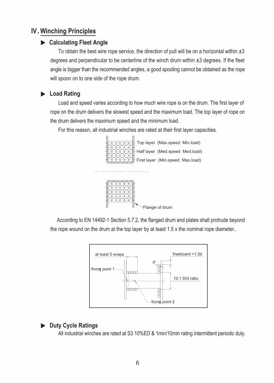
Load Rating Load and speed varies according to how much wire rope is on the drum. The first layer of rope on the drum delivers the slowest speed and the maximum load. The top layer of rope on the drum delivers the maximum speed and the minimum load. For this reason, all industrial winches are rated at their first layer capacities.
According to EN 14492-1 Section 5.7.2, the flanged drum end plates shall protrude beyond the rope wound on the drum at the top layer by at least 1.5 x the nominal rope diameter..
7
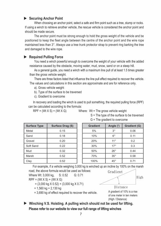
For example, if a vehicle weighing 3,000 kg is winched up an incline by 100% on the marsh road, the above formula would be used as follows: Where Wt: 3,000 kg, S: 0.52 G: 0.71 RPF = (Wt X S) + (Wt X G) = (3,000 kg X 0.52) + (3,000 kg X 0.71) = 1,560 kg + 2,130 kg = 3,690 kg of effect required to recover the vehicle.
Winching V.S. Hoisting. A pulling winch should not be used for lifting. Please refer to our website to view our full range of lifting winches
A gradient of 10% is a rise of one meter in ten meters (High / Distance)
Surface Type Surface Drag (S) Gradient Angle ( ) Gradient (G)
Metal 0.15 5% 3° 0.06
Sand 0.18 10% 6° 0.11
Gravel 0.20 20% 11° 0.2
Soft Sand 0.22 30% 17° 0.3
Mud 0.32 50% 26° 0.44
Marsh 0.52 70% 35° 0.58
Clay 0.52 100% 45° 0.71
°
In recovery and loading the winch is used to pull something, the required pulling force (RPF) can be calculated according to the formula: RPF = (Wt X S) + (Wt X G) Where: Wt = The gross vehicle weight S = The type of the surface to be traversed G = The gradient to overcome
Securing Anchor Point When choosing an anchor point, select a safe and firm point such as a tree, stump or rocks. If using a winch to retrieve another vehicle, the rescue vehicle is considered the anchor point and should be made secure. The anchor point must be strong enough to hold the gross weight of the vehicle and be positioned to keep the fleet angle between the centre of the anchor point and the wire rope maintained less than 3°. Always use a tree trunk protector strap to prevent ring barking the tree and damaged to the wire rope.
Required Pulling Force You need a winch powerful enough to overcome the weight of your vehicle with the added resistance caused by the obstacle, moving water, mud, snow, sand or on a steep hill. As a general guide, you need a winch with a maximum line pull of at least 1.5 times greater than the gross vehicle weight. There are three factors listed that influence the line pull effect required to recover the vehicle. The values and calculations in this section are approximate and are for reference only. a). Gross vehicle weight b). Type of the surface to be traversed c). Gradient to overcome
VI . Accessories
8
Roller Fairlead The use of 4 ways roller fairlead can eliminate the contacting friction because the fairlead rollers contact with the wire rope. But the fairlead does not insure the wire rope will wind onto the drum in an orderly manner. The proper fleet angle within 3° must be maintained for the wire rope to wind onto the drum in an orderly manner. If the proper fleet angle is not maintained, it can result in damage to the winch and wire rope.
Cable Tensioner The purpose of cable tensioner device is to keep the wire rope tight on the drum while the winch is in free spool mode or while there is no load on the wire rope.
V . Standards ComplianceComeup Industrial Winches comply with the following regulations
1. European Standards of EN 14492-1 for Power Driven Winches came to effect from 29th. December 2009 2. The latest Machinery Safety regulations of 2006/42/EC for machinery Directive. 3. The latest Machinery Safety regulations of 2004/108/EC for EMC Directive. 4. SAE International Surface Vehicle Standard J706
Extracts from the Directive & Comeup compliance: 1. EN 14492-1 Section 5.15.6 Wire Rope Wire rope minimum break to be twice winch rating 2. EN 14492-1 Section 5.7.2 Rope Drum Rope drum mean diameter to be 10 times the diameter of the wire rope 3. EN 14492-1 Section 5.7.6 Rope Fastening onto the rope drum Rope attachment to withstand 2.5 times the winch rating Rope must have at least two wraps winding before fixing point 4. EN 14492-1 Section 5.15.5 Brake Winch to hold full rated load 5. EN 14492-1 Section 5.15.2 Rated Capacity limiters The thermal overload cutout limit the driving power of the motor prevents overloading
To comply with EN 14492-1, the following optional accessories must be fitted to all winches ● Wire rope with 1,960 N/mm2 grade ● Rope drum cover ● Emergency stop kit ● Isolator switch When using and installing a winch, the owner or end user shall ensure that all legal requirements are completely complied with
VII. Hydraulic Operation (For Yak Winch and HV Winch)
9
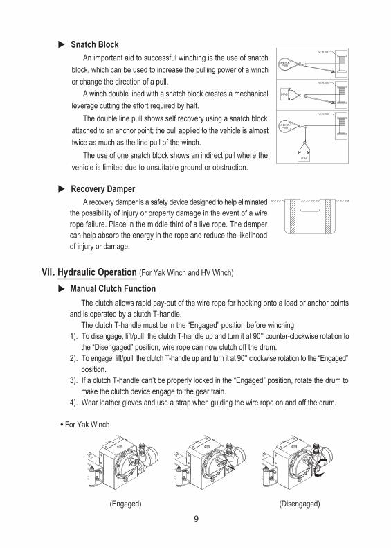
Manual Clutch Function The clutch allows rapid pay-out of the wire rope for hooking onto a load or anchor points and is operated by a clutch T-handle. The clutch T-handle must be in the “Engaged” position before winching. 1). To disengage, lift/pull the clutch T-handle up and turn it at 90° counter-clockwise rotation to the “Disengaged” position, wire rope can now clutch off the drum. 2). To engage, lift/pull the clutch T-handle up and turn it at 90° clockwise rotation to the “Engaged” position. 3). If a clutch T-handle can’t be properly locked in the “Engaged” position, rotate the drum to make the clutch device engage to the gear train. 4). Wear leather gloves and use a strap when guiding the wire rope on and off the drum.
● For Yak Winch
(Engaged) (Disengaged)
Recovery Damper A recovery damper is a safety device designed to help eliminated the possibility of injury or property damage in the event of a wire rope failure. Place in the middle third of a live rope. The damper can help absorb the energy in the rope and reduce the likelihood of injury or damage.
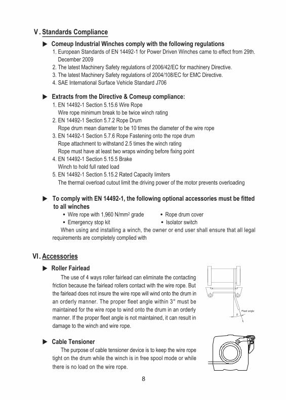
Snatch Block An important aid to successful winching is the use of snatch block, which can be used to increase the pulling power of a winch or change the direction of a pull. A winch double lined with a snatch block creates a mechanical leverage cutting the effort required by half. The double line pull shows self recovery using a snatch block attached to an anchor point; the pull applied to the vehicle is almost twice as much as the line pull of the winch. The use of one snatch block shows an indirect pull where the vehicle is limited due to unsuitable ground or obstruction.
10
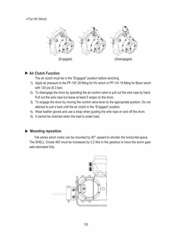
Mounting reposition Yak series winch motor can be mounted by 90° upward to shorten the horizontal space. The SHELL Omala 460 must be increased by 0.2 litre in the gearbox to have the worm gear sets lubricated fully.
Air Clutch Function The air clutch must be in the “Engaged” position before winching. 1). Apply air pressure to the PF-1/8”-28 fitting for HV winch or PF-1/4’-19 fitting for Bison winch with 120 psi (8.3 bar). 2). To disengage the drum by operating the air control valve to pull out the wire rope by hand. Pull out the wire rope but leave at least 5 wraps on the drum. 3). To engage the drum by moving the control valve lever to the appropriate position. Do not attempt to pull a load until the air clutch in the “Engaged” position. 4). Wear leather gloves and use a strap when guiding the wire rope on and off the drum. 5). It cannot be clutched when the load is under load.
(Engaged) (Disengaged)
● For HV Winch
11
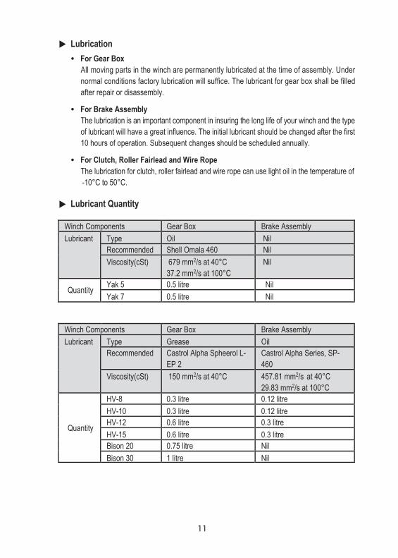
Lubrication ● For Gear Box All moving parts in the winch are permanently lubricated at the time of assembly. Under normal conditions factory lubrication will suffice. The lubricant for gear box shall be filled after repair or disassembly.
● For Brake Assembly The lubrication is an important component in insuring the long life of your winch and the type of lubricant will have a great influence. The initial lubricant should be changed after the first 10 hours of operation. Subsequent changes should be scheduled annually.
● For Clutch, Roller Fairlead and Wire Rope The lubrication for clutch, roller fairlead and wire rope can use light oil in the temperature of -10°C to 50°C.
Lubricant Quantity
Winch Components Gear Box Brake Assembly Lubricant Type Oil Nil
Recommended Shell Omala 460 Nil Viscosity(cSt) 679 mm2/s at 40°C
37.2 mm2/s at 100°C Nil
Quantity Yak 5 0.5 litre Nil Yak 7 0.5 litre Nil
Winch Components Gear Box Brake Assembly Lubricant Type Grease Oil
Recommended Castrol Alpha Spheerol L-EP 2
Castrol Alpha Series, SP-460
Viscosity(cSt) 150 mm2/s at 40°C 457.81 mm2/s at 40°C 29.83 mm2/s at 100°C
Quantity
HV-8 0.3 litre 0.12 litre HV-10 0.3 litre 0.12 litre HV-12 0.6 litre 0.3 litre HV-15 0.6 litre 0.3 litre Bison 20 0.75 litre Nil Bison 30 1 litre Nil
12
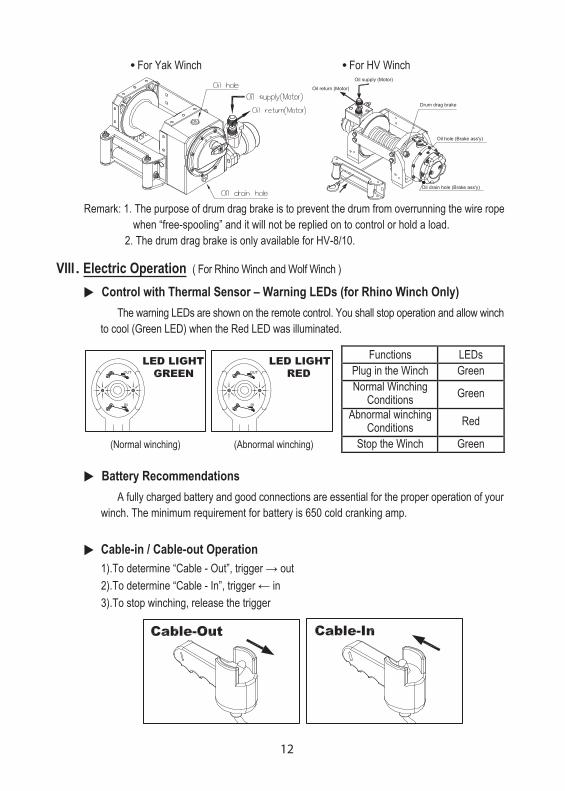
Cable-in / Cable-out Operation 1).To determine “Cable - Out”, trigger → out 2).To determine “Cable - In”, trigger ← in 3).To stop winching, release the trigger
VIII . Electric Operation ( For Rhino Winch and Wolf Winch )
Control with Thermal Sensor – Warning LEDs (for Rhino Winch Only) The warning LEDs are shown on the remote control. You shall stop operation and allow winch to cool (Green LED) when the Red LED was illuminated.
Battery Recommendations A fully charged battery and good connections are essential for the proper operation of your winch. The minimum requirement for battery is 650 cold cranking amp.
Remark: 1. The purpose of drum drag brake is to prevent the drum from overrunning the wire rope when “free-spooling” and it will not be replied on to control or hold a load. 2. The drum drag brake is only available for HV-8/10.
Functions LEDs Plug in the Winch Green Normal Winching
Conditions Green
Abnormal winching Conditions Red
Stop the Winch Green (Normal winching) (Abnormal winching)
● For Yak Winch ● For HV Winch

13
● For Yak/HV/Bison/Wolf Winch ● For Rhino Winch
Clutch Function The clutch allows rapid pay-out of the wire rope for hooking onto a load or anchor points and is operated by a clutch T-handle. The clutch T-handle must be in the “Engaged” position before winching. 1). To disengage, lift the clutch T-handle up for Rhino Winch and turn it at 90° counter-clockwise rotation to the “Disengaged” position, wire rope can now clutch off the drum. 2). To engage, lift the clutch T-handle up for Rhino Winch and turn it at 90° clockwise rotation to the “Engaged” position. 3). If a clutch T-handle can’t be properly locked in the “Engaged” position, rotate the drum to make the clutch device engage to the gear train. 4). Wear leather gloves and use a strap when guiding the wire rope on and off the drum.
● For Rhino Winch ● For Wolf Winch
Wire Rope Replacement Never use a wire rope of a different size or material. The wire rope end shall be inserted through a hole in the drum and a screw is used to clamp the wire rope in place. This rope attachment is simple and ingenious. 1). Disengage the clutch T-handle. 2). Spool the entire wire rope, and then remove it from the drum. 3). For Yak/HV/Bison/Wolf Winch, place the replacement wire rope through the roller fairlead opening, pass below the drum, and insert it into the hole on the drum core. 3-1). For Rhino Winch, place the replacement wire rope through the roller fairlead opening and drum core. Escape from hole 2 and wind 5 wraps on the drum. Insert the rope to the drum core from hole 1 4). Tighten the screw downwards to secure the wire rope. 5). The red paint markings on the wire rope means 3 metres remains on the drum.
(Engaged) (Disengaged) (Engaged) (Disengaged)
14
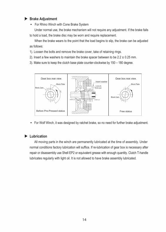
Brake Adjustment ● For Rhino Winch with Cone Brake System Under normal use, the brake mechanism will not require any adjustment. If the brake fails to hold a load, the brake disc may be worn and require replacement. When the brake wears to the point that the load begins to slip, the brake can be adjusted as follows: 1). Loosen the bolts and remove the brake cover, take of retaining rings. 2). Insert a few washers to maintain the brake spacer between to be 2.2 ± 0.25 mm. 3). Make sure to keep the clutch base plate counter-clockwise by 150 – 180 degree.
● For Wolf Winch, it was designed by ratchet brake, so no need for further brake adjustment.
Lubrication All moving parts in the winch are permanently lubricated at the time of assembly. Under normal conditions factory lubrication will suffice. If re-lubrication of gear box is necessary after repair or disassembly use Shell EP2 or equivalent grease with enough quantity. Clutch T-handle lubricates regularly with light oil. It is not allowed to have brake assembly lubricated.
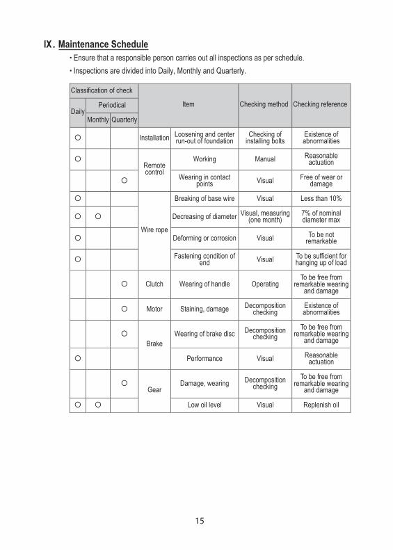
15
Classification of check
Periodical Daily
Monthly Quarterly
Item Checking method Checking reference
Installation Loosening and center run-out of foundation
Checking of installing bolts
Existence of abnormalities
Working Manual Reasonable actuation
Remote control Wearing in contact
points Visual Free of wear or damage
Breaking of base wire Visual Less than 10%
Decreasing of diameter Visual, measuring (one month)
7% of nominal diameter max
Deforming or corrosion Visual To be not remarkable
Wire rope
Fastening condition of end Visual To be sufficient for
hanging up of load
Clutch Wearing of handle Operating To be free from
remarkable wearing and damage
Motor Staining, damage Decomposition checking
Existence of abnormalities
Wearing of brake disc Decomposition checking
To be free from remarkable wearing
and damage
Brake
Performance Visual Reasonable actuation
Damage, wearing Decomposition checking
To be free from remarkable wearing
and damage
Gear
Low oil level Visual Replenish oil
IX . Maintenance Schedule ● Ensure that a responsible person carries out all inspections as per schedule. ● Inspections are divided into Daily, Monthly and Quarterly.

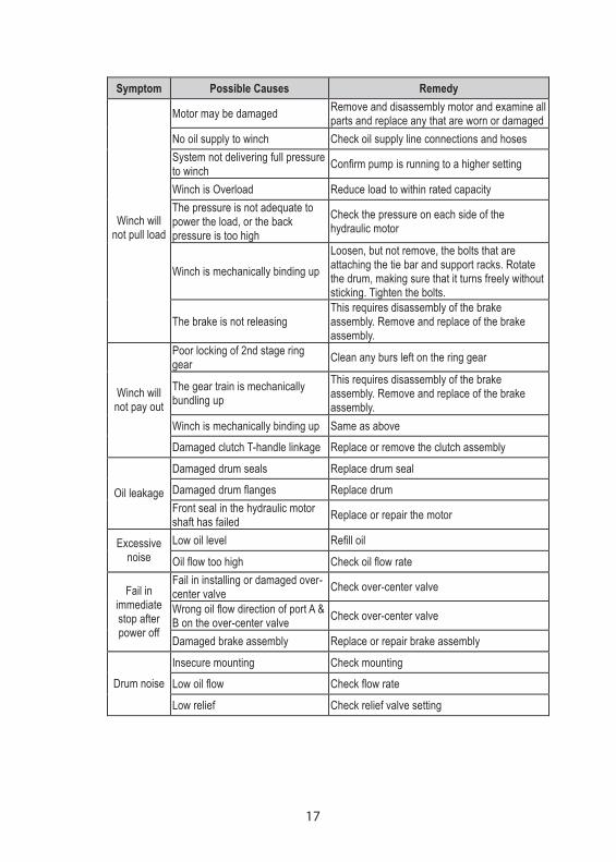
X . Trouble Shooting
16
For Hydraulic Winch (Yak Winch, HV Winch and Bison Winch) In most cases, the cause of malfunction is found in the hydraulic system. Before the winch
is removed from its mounting and disassembled, all of hydraulic system components should be
check for proper function. When checking oil pressure and volume in the hydraulic system, make
certain that the hydraulic reservoir is filled to the top level.
1. Hydraulic Oil Volume The hydraulic oil volume relates to the line speed or rpm of the winch. Therefore if the winch
does not produce the specified maximum line speed or drum rpm, a loss of hydraulic flow in the
hydraulic system can be analysed. In this condition exists, install a flow meter into the hydraulic
system to check the volume supplied to the pressure port of the hydraulic winch motor when the
winch control is completely opened.
2. Hydraulic Pressure The hydraulic pressure relates to the line pull of the winch. Therefore if the winch does not
produce the specified maximum line pull, a loss of hydraulic pressure in the hydraulic system
can be analysed. In the condition exists, install a pressure gauge into the pressure line leading
to the pulling port on the hydraulic winch motor.
3. Troubleshooting chart Only if the hydraulic system has been checked and found to be in order, use the following
indications for possible causes of failure in the winch.
17
Symptom Possible Causes Remedy
Motor may be damaged Remove and disassembly motor and examine all parts and replace any that are worn or damaged
No oil supply to winch Check oil supply line connections and hoses System not delivering full pressure to winch Confirm pump is running to a higher setting
Winch is Overload Reduce load to within rated capacity The pressure is not adequate to power the load, or the back pressure is too high
Check the pressure on each side of the hydraulic motor
Winch is mechanically binding up Loosen, but not remove, the bolts that are attaching the tie bar and support racks. Rotate the drum, making sure that it turns freely without sticking. Tighten the bolts.
Winch will
not pull load
The brake is not releasing This requires disassembly of the brake assembly. Remove and replace of the brake assembly.
Poor locking of 2nd stage ring gear Clean any burs left on the ring gear
The gear train is mechanically bundling up
This requires disassembly of the brake assembly. Remove and replace of the brake assembly.
Winch is mechanically binding up Same as above
Winch will not pay out
Damaged clutch T-handle linkage Replace or remove the clutch assembly
Damaged drum seals Replace drum seal
Damaged drum flanges Replace drum Oil leakage Front seal in the hydraulic motor shaft has failed Replace or repair the motor
Low oil level Refill oil Excessive noise Oil flow too high Check oil flow rate
Fail in installing or damaged over- center valve Check over-center valve
Wrong oil flow direction of port A & B on the over-center valve Check over-center valve
Fail in immediate stop after power off
Damaged brake assembly Replace or repair brake assembly
Insecure mounting Check mounting
Low oil flow Check flow rate Drum noise
Low relief Check relief valve setting
18
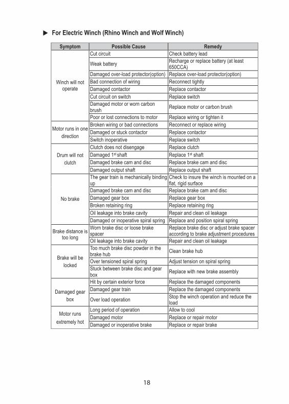
For Electric Winch (Rhino Winch and Wolf Winch)
Symptom Possible Cause Remedy Cut circuit Check battery lead
Weak battery Recharge or replace battery (at least 650CCA)
Damaged over-load protector(option) Replace over-load protector(option) Bad connection of wiring Reconnect tightly Damaged contactor Replace contactor Cut circuit on switch Replace switch Damaged motor or worn carbon brush Replace motor or carbon brush
Winch will not operate
Poor or lost connections to motor Replace wiring or tighten it Broken wiring or bad connections Reconnect or replace wiring Damaged or stuck contactor Replace contactor Motor runs in one
direction Switch inoperative Replace switch Clutch does not disengage Replace clutch Damaged 1st shaft Replace 1st shaft Damaged brake cam and disc Replace brake cam and disc
Drum will not clutch
Damaged output shaft Replace output shaft The gear train is mechanically binding up
Check to insure the winch is mounted on a flat, rigid surface
Damaged brake cam and disc Replace brake cam and disc Damaged gear box Replace gear box Broken retaining ring Replace retaining ring Oil leakage into brake cavity Repair and clean oil leakage
No brake
Damaged or inoperative spiral spring Replace and position spiral spring Worn brake disc or loose brake spacer
Replace brake disc or adjust brake spacer according to brake adjustment procedures Brake distance is
too long Oil leakage into brake cavity Repair and clean oil leakage Too much brake disc powder in the brake hub Clean brake hub
Over tensioned spiral spring Adjust tension on spiral spring Brake will be locked Stuck between brake disc and gear
box Replace with new brake assembly
Hit by certain exterior force Replace the damaged components Damaged gear train Replace the damaged components
Damaged gear
box Over load operation Stop the winch operation and reduce the load
Long period of operation Allow to cool Damaged motor Replace or repair motor Motor runs
extremely hot Damaged or inoperative brake Replace or repair brake

PN 881408 Ver:03Specifications subject to change without notice
COMEUP INDUSTRIES INC.No.112, Nanyang St., Xizhi Dist., New Taipei City, Taiwan 22152Tel: +886-2-2694-7011 / Fax: +886-2-2694-7053Email: [email protected]://www.comeupwinch.com