industry binder 2010 -...
TRANSCRIPT

Industry binder 2010
FOAMGLAS® Products, Insulation systems,
Accessories products
www.foamglas.com
Table of contents
General O1 Production
O2 10 properties
O3 Why to use FOAMGLAS®
O4 Where to use FOAMGLAS®
Insulation Systems I02 Low temperature piping and
equipment
I02-10 Liquid nitrogen and oxygen pipes
I02-20 LNG piping and equipment
I02-25 Ethylene piping and equipment
I02-60 Hydrocarbon fire resistance at low temperature
I02-70 TEROSTAT-PC for cold-service applications
I02-90 Chilled water
I03 High temperature piping and equipment
I03-70 TEROSTAT-PC for hot-service applications
I04 Dual temperature piping and equipment
I06 Vertical storage tank walls and roofs
I07 Low temperature storage spheres
I08 Secondary insulation protection for LNG tank walls
I10 Offshore platforms and ships
I21 Industrial chimneys
I22 Liquefied gas tank bases
I23 Installation procedure for a LNG tank corner protection
I26 Liquefied oxygen and nitrogen tank bases
I28-20 Hot tank bases up to +150°C
I28-30 Hot tank bases up to +250°C
I28-40 Hot salt tank bases
I30 Pool Fire Suppressant (PFS)
Products A02 FOAMGLAS® T4 A03 FOAMGLAS® S3 A05 FOAMGLAS® F A08 Block dimensions A10 Facts and Figures A11 Pipe shells – PSH A12 Pipe segments – PSG/PSQ A13 Elbows – E90/E45 A14.1 Flanges – F15/F30 A14.2 Valves – V15/V30 A15 Tank segments – TSG A16 Head segments – HKH/HEH A40 Inside, outside and joint surface
Accessories P05 PC® 88 Adhesive P06 PC® 56 Adhesive P08 PC® 58 Adhesive P11 PC® 11 Adhesive P12 PC® 500 P13 PC® 74A2 P14 PC® Hotmelt Adhesive P18 PC® 18 Adhesive P20 PC® Low temperature anti-abrasive
(LTAA) P21 PC® High temperature anti-abrasive
(HTAA) P22 PC® 85 Powder P30 PITTCOTE® 300 P31 PITTCOTE® 404 P41 PITTSEAL® 444 P45 PC® 80M Mortar P50 PC® Fabric 79 P52 PC® 150 P60 PITTWRAP Standard P61 PITTWRAP Self-Sealing P70 TEROSTAT-PC / PC® 700K / PITTCOURSE® 100 / PC® 47 Adhesive

Pittsburgh Corning GmbH (Austria)
Pittsburgh Corning Nederland B.V.
Pittsburgh Corning Schweiz A.G.
FOAMGLAS® Península Ibérica
Pittsburgh Corning Scandinavia ab.
Deutsche Pittsburgh Corning GmbH
Pittsburgh Corning UK Ltd.
Pittsburgh Corning Norway
Pittsburgh Corning Italy
Pittsburgh Corning France S.A.
The innovative insulation people
Pittsburgh Corning Europe is also represented in: Croatia, Czech Republic, Denmark, Greece, Hungary, Poland, Rumania, Russian Federation, Slovak Republic, Slovenia, Ukraine and Africa.
O1
08/02
1. MANUFACTURING PROCESSThe manufacturing process of FOAMGLAS® comprises 4 stages: − Glass production − Grinding of the glass to form a glass
powder, and mixing with carbon. − Foaming and annealing of glass − Finishing of the product. Sand is the basic material. Additives introduced during the first stage of production produce a special type of glass. This product is then extruded and crushed to form a glass powder. A mixture of the powder
and carbon is placed into special moulds and put into an oven heated to approximately 1000°C. In the oven, the carbon oxidises and forms gas bubbles that start expansion. The excess carbon gives FOAMGLAS® its characteristic black colour. When the expansion process is complete, the product is taken out of the moulds and passed trough a long annealing furnace. The slabs are then cut to size, tested and packed. To assure the best insulation product possible, Pittsburgh Corning technicians run several quality control tests throughout all stages of production.
2. PRODUCTION SCHEME
Weigh batching
Introduction ofraw materials
Oven 1400°C
Molten glass
Pure glass Control roomSolid glass
Ball mill Addition ofcarbon
Weigh batching
Cellulating furnace
Annealing furnace
Cutting, squaring
Packing
Stacking on pallets
Flat slabs to fabricating shop
PRODUCTION

O2-07/93 1/2
O2
08/02
10 EXCEPTIONAL PROPERTIES OF FOAMGLAS® CELLULAR GLASS 1. Waterproof. FOAMGLAS® insulation, composed of hermetically sealed glass cells, is totally waterproof. Its thermal resistance remains constant in damp atmospheres.
2. Impervious to water vapour. FOAMGLAS® cellular glass is completely impervious to water vapour. Its insulating capacity cannot be affected by internal condensation.
3. Resistant to attack by acids. FOAMGLAS® cellular glass is not affected by atmospheric chemicals and is highly resistant to most acids. Its properties and characteristics remain constant throughout its service life.
ACID
4. High compressive strength. FOAMGLAS® cellular glass has exceptionally high compressive strength, and there is thus no risk of deterioration under heavy load conditions.
10 PROPERTIES

Pittsburgh Corning GmbH (Austria)
Pittsburgh Corning Nederland B.V.
Pittsburgh Corning Schweiz A.G.
FOAMGLAS® Península Ibérica
Pittsburgh Corning Scandinavia ab.
Deutsche Pittsburgh Corning GmbH
Pittsburgh Corning UK Ltd.
Pittsburgh Corning Norway
Pittsburgh Corning Italy
Pittsburgh Corning France S.A.
The innovative insulation people
Pittsburgh Corning Europe is also represented in: Croatia, Czech Republic, Denmark, Greece, Hungary, Poland, Rumania, Russian Federation, Slovak Republic, Slovenia, Ukraine and Africa.
5. Dimensionally stable. With its perfect dimensional stability, FOAMGLAS® cellular glass remains totally free from deformation under varying conditions of relative humidity.
6. Incombustible. Being composed of pure glass, FOAMGLAS® cellular glass is completely incombustible. It is totally flame retarding and does not support any combustion, thus constituting a safety factor in the event of fire.
9. Fibre, CFC and HCFC free FOAMGLAS® cellular glass contains no fibers, CFC or HCFC.
7. Easy to cut. FOAMGLAS® cellular glass can easily be cut to a high degree of accuracy using ordinary cutting tools.
8. Vermin proof. FOAMGLAS® cellular glass is an inorganic material and therefore provides neither food nor protection for rodents, insects, micro-organisms and bacteria.
10. Ecological Product. FOAMGLAS® cellular glass quickly pays back the energy used for its production.

1/4 O3 – 08/02
O3
08/02
1. FIRE AND SMOKE Fire is a very serious problem for industrial and building applications. It causes every year several thousand deaths and damages are evaluated at several billion dollars in the USA and at a similar level in Europe. Insulation material plays a major role in its development and propagation. During a long time, a misleading terminology based on some equally misleading testing methods have lead to questionable evaluation of the fire risk. This confusion especially applies to some plastic
foams which also present a particular danger caused by smoke and toxic gases - the first cause of death before flames. In contrast, FOAMGLAS® insulation presents a high degree of fire safety as proven by severe product and insulation system tests and confirmed by large fire analysis and expert opinions. In some countries, it is recognised by favourable insurance rates.
FOAMGLAS® cellular glass is classified noncombustible.
ISO 1182 • ASTM E-136 • BS 476 - Part 4 • NEN 3881 • DIN 4102 Teil 1
2. COMBUSTIBLE LIQUIDS IN INSULATION Fires can result from the absorption of combustible liquids, such as oils and heat transfer fluids, in insulation. This comes about from a slow oxidation of the organic liquids that will cause a temperature build-up within the insulation that will eventually lead to ignition. As a consequence, non absorptive and non combustible FOAMGLAS® insulation is
recommended for application where leaks of organic liquids are possible. A variety of FOAMGLAS® insulation systems have been employed for such applications in both the US and Europe. FOAMGLAS® insulation should also be considered for low temperature applications to minimise the possibility of the condensation of hydrocarbon gases or liquid oxygen.
FOAMGLAS® insulation is non-wicking and totally noncombustible.
3. LIQUID WATER ABSORPTION AND RETENTION IN INSULATION It has been estimated that "98% of the problems with insulation systems are due to moisture." Moisture generally enters an insulation system through ineffective vapor barrier. Surprisingly, even insulation materials operating at high temperature can retain extremely high quantities of water. Since FOAMGLAS® insulation is composed of a
network of non-interconnecting glass cells, it has outstanding resistance to liquid water and even water vapour. This resistance to water intrusion has been demonstrated in both the laboratory and the field. High temperature industrial applications that rely on the water resistance of FOAMGLAS® insulation include pipe lines, tanks and process equipment.
WHY TO USE FOAMGLAS®

2/4 O3 – 08/02
4. WATER VAPOUR TRANSPORT AND CONDENSATION Practically all materials allow water vapour to pass, only glass and metal do not. When water vapour enters a material layer where the dew point temperature is met, it condenses to water or even if the temperature is below freezing point, ice is formed. This affects seriously the insulation efficiency, because insulation must be dry and stay dry. In practice it is extremely
difficult to keep insulation dry only by using a vapour check, as it is only a thin layer and easily damaged. Condensation not only occurs in the cold field, but also when dealing with operating temperatures that are above ambient air conditions. Condensation means also corrosion that is also one of the big problems to deal with.
FOAMGLAS® cellular glass µ value = ∞∞∞∞
permeability = 0
5. THERMAL EFFICIENCY IN REAL LIFE The task of thermal insulation is to provide reliable and long-term thermal resistance despite potential harsh environmental and service conditions. The efficiency of many thermal insulations is easily degraded by moisture and/or mechanical abuse. This degradation leads to increased operating costs and can cause problems with process control or personnel protection, and can
lead to additional degradation both of the insulation and the vessel or equipment. There are many causes or mechanisms for the increased conductivity of insulations. Unfortunately designers/users may be mislead by common but incorrect concepts that result in the severity of these problems being significantly underestimated.
Thermal conductivity of Water 0.55 W/(m.K) Ice at 0°C 2.20 W/(m.K)
1 % vol. of moisture increases thermal conductivity by 30%
("Common In-Plant Problems Encountered with Insulation", George Lang, Chemical Processing,Jan (1984), pp. 38-39)
6. METAL CORROSION Wet thermal insulation can accelerate metal corrosion that, in turn, can cause serious economic and safety consequences. Serious corrosion is generally associated with absorptive insulations. Corrosion is most severe in the temperature range where liquid water can be present. The corrosion of carbon steel is accelerated by acidity while chloride content is
required for the stress corrosion cracking of stainless steel. Since FOAMGLAS® insulation is impermeable, it provides a barrier to moisture intrusion. Since it is slightly alkaline there is no possibility of accelerated corrosion of carbon steel. In addition it is qualified for use with stainless steel.
FOAMGLAS® cellular glass is compatible with carbon steel and stainless steel

3/4 O3 – 08/02
7. CHEMICAL DURABILITY The ultimate performance of an insulation product may be critically affected by the chemical environment to which it is exposed while in service. Therefore, the insulation product selected for an application must be resistant to all
liquids and/or vapours to which it may be exposed. FOAMGLAS® cellular glass insulation is, without question, the most chemically durable of all the insulation products available in the marketplace.
FOAMGLAS® insulation is 100% glass.
8. DIMENSIONAL STABILITY The dimensional stability of an insulation material is a property that is absolutely necessary for the faultiness function of an insulating system. The term implies not only the reversible linear coefficient of expansion that depends on the temperature but also irreversible changes of dimensions, which can be caused by influences of temperature, water or humidity and by too high loads. Damages created from inadequate dimensional stability become apparent in different ways: Between slabs and shells the
joints appear as heat- or cold bridges. Slabs can warp or bowl, resulting in damages of coatings or waterproofing materials. Finally insufficient dimensional stability affects also the insulating power of an insulation system in an extent that can be neither foreseen nor predetermined. With FOAMGLAS® as insulating material all these problems are avoided because this material has not only a very small coefficient of expansion but also an excellent dimensional stability under the influence of temperature and/or humidity.
9. COMPRESSIVE STRENGTH In the case of insulating materials, compressive strength is needed for many applications like cryogenic tank bottom insulation, low temperature tank bottom, semi-underground conical digesters, high temperature tank bottoms, industrial floors, underground pipe and vessel insulation, insulated pipe supports and hangers and more generally to withstand mechanical abuses like traffic that does happen in real life. The different types of FOAMGLAS® insulation have average ultimate compressive strengths
ranging from 0.5 to 1.2 N/mm², measured with extremely limited deformation. This fact favours easy and simple design for load bearing insulation systems. In contrast, many other insulating materials have lower compressive strength and they are measured under 10 % deformation. Within the application temperature limit, FOAMGLAS® compressive strength is practically not affected by the temperature.
Compressive strength of FOAMGLAS® cellular glass From 0.5 N/mm² up to 1.2 N/mm²
and unaffected up to its temperature limits.

Pittsburgh Corning GmbH (Austria)
Pittsburgh Corning Nederland B.V.
Pittsburgh Corning Schweiz A.G.
FOAMGLAS® Península Ibérica
Pittsburgh Corning Scandinavia ab.
Deutsche Pittsburgh Corning GmbH
Pittsburgh Corning UK Ltd.
Pittsburgh Corning Norway
Pittsburgh Corning Italy
Pittsburgh Corning France S.A.
The innovative insulation people
Pittsburgh Corning Europe is also represented in: Croatia, Czech Republic, Denmark, Greece, Hungary, Poland, Rumania, Russian Federation, Slovak Republic, Slovenia, Ukraine and Africa.
10. VERMIN RESISTANCE OF INSULATION MATERIALS The resistance of insulation materials against rodents and vermin is a property that is not very often considered when buildings and/or technical installations are planned. When insulation is used for underground walls and foundations, for agricultural buildings or for exterior technical installations, gnawing or boring animals can cause heavy damage. This can have consequences from the loss of thermal performance and/or mechanical strength up to
the complete deterioration of the insulating system itself. Not only carefully executed tests but also practical experience shows that FOAMGLAS® insulation is not only resistant against rats and mice but it is also not destroyed by gnawing and boring insects or termites. No other insulation material offers such a high safety factor from the damage caused by such animals as does FOAMGLAS® insulation.
11. ECOLOGICAL INSULATION FOAMGLAS® cellular glass is produced in 2 major steps. The first consists in producing glass. This glass is crushed and converted to powder in a ball mill. The second step is the foaming and annealing of the cellulated glass "FOAMGLAS®". No foaming agent is used during this phase, such as CFCs or HCFCs that deplete the ozone layer. This process is consuming energy at a relatively low level and the consumed energy is commonly recovered in much less than 1 year of the service
life of the insulation. The gas in the cells is CO2 and is only released when the material is cut or destroyed. The amount of CO2 coming out of the cells is negligible compared to the amount released by one man when breathing. Therefore this amount does not contribute to the greenhouse effect. FOAMGLAS® cellular glass can be recycled without special protection measures for the Environment or people's health and its reinsertion in nature remains neutral.
Ecological classification of FOAMGLAS® cellular glass Recommended without reservations
Class 3

9/4 O4 – 08/02
O4
08/02
1. MAIN REASONS TO USE FOAMGLAS® Process and application temperatures have been classified in three ranges where the main reasons to use FOAMGLAS® cellular glass are: Below ambient: − perfect moisture resistance − protection against the corrosion risk, − protection against freezing − dimensional stability − compressive strength Ambient to +120°C: − protection against corrosion risk − fire hazard in case of leakage of combustible
product − no water absorption − dimensional stability − compressive strength
From +120 to 430°C: − fire hazard with combustible liquids − compressive strength − protection against corrosion − dimensional stability Many FOAMGLAS® cellular glass applications are mentioned with an appreciation of their use: - = very limited ± = limited to moderate + = moderate to high ++ = very high
2. REFINERY PROCESS COLD
< 20°C WARM
20 to 120°C HOT
> 120°C COMMENTS
ATMOSPHERIC DISTILLATION -
GAS, LPG, GASOLINE FRACTIONATION + ± Fire
VACUUM DISTILLATION ± Heat Tracing Lines
CATALYTIC REFORMING -
ISOMERISATION -
CATALYTIC CRACKING -
VISBREAKING
COKING PROCESSES -
HYDROCONVERSION ± -
ALKYLATION (HF) - -
ALKYLATION (H2S04) + -
DIMERSOL -
POLYMERISATION -
HYDROTREATMENT PROCESSES -
CHEMICAL TREATMENT PROCESSES Limited insulation required
SOLVENT DESASPHALTING ± ±
AMINE UNIT +
SULPHUR UNIT + + On traced lines, crystallisation risk
WHERE TO USE
FOAMGLAS®

10/4 O4 – 08/02
3. GAS PROCESSING
PROCESS COLD < 20°C
WARM 20 to 120°C
HOT > 120°C
COMMENTS
H2S, CO2 REMOVAL PROCESSES ++ ± Depending on process LPG, LNG RECOVERY PROCESSES ++ ± LIQUEFACTION PROCESSES ++ Low temperature process LNG RECEIVING TERMINAL ++ All FOAMGLAS® cellular
glass to be considered SYNTHESIS GASES ++ INDUSTRIAL GASES ++ LOX/LIN - no organics
4. PETROCHEMISTRY
PROCESS COLD < 20°C
WARM 20 to 120°C
HOT > 120°C
COMMENTS
AMMONIA ++ ± - Storage (++) CARBON MONOXIDE ++ Cryogenic process: (++) METHANOL ++ ± Leakage MTBE ± Leakage UREA ± - BUTADIENE ++ ± - STEAM CRACKING ++ + ± ISOBUTENE ++ + AROMATICS + + CUMENE ± ± Traced PHENOL/ACETONE ± ± ETHYLBENZENE ± - STYRENE + Fractionation section NITROBENZENE ± ANILINE ± - PARAXYLENE: (CRYSTALLISATION) + ± Crystallisation process PARAXYLENE: (PAREX) ± - ETHYLENE OXIDE ++ ++ explosion risk ETHYLENE GLYCOL ++ ++ PROPYLENE OXIDE ++ ++ PROPYLENE GLYCOL ++ ++ N. BUTANOL ± ISOPROPANOL + HIGHER ALCOHOLS + + 2-ETHYL HEXANOL + + ACETALDEHYDE ± ACETIC ACID ± ± ACRYLATES ± ACRYLIC ACID ± ± ACRYLONITRILE ++ ± ± VINYL ACETATE ± VINYL CHLORIDE ++ + ± ADIPIC ACID ± - MALEIC ANHYDRIDE ± - DMT ± ± TPA ± ± MDI + ± ± TDI ++ ± ± POLYETHER-POLYOLS ± POLYETHYLENE (LDPE) ± - POLYETHYLENE (HDPE) ++ + POLYETHYLENE (LINEAR LDPE) + POLYPROPYLENE ++ + + POLYSTYRENE ± ± PVC ± LAB ± ± POLYBUTADIENE + + + SBR +

11/4 O4 – 08/02
5. STORAGE TANKS
APPLICATION COLD < 20°C
WARM 20 to 120°C
HOT > 120°C
COMMENTS
VERTICAL TANK: BOTTOM ++ ++ ++ Compressive strength VERTICAL TANK: WALLS AND ROOFS ++ + - SPHERICAL TANK ++ +
6. MISCELLANEOUS
APPLICATION COLD < 20°C
WARM 20 to 120°C
HOT > 120°C
COMMENTS
OFF-SHORE ++ ++ ++ Fire-corrosion BITUMEN TANKS - TANKERS ++ ++ Fire HEAT TRANSFER ++ Fire-Explosion SULPHUR PITS ++ PHARMACEUTICAL ++ ++ ++ Corrosion - bacteriological
cycling temperature COSMETICS ++ +
7. FOOD
APPLICATION COLD < 20°C
WARM 20 to 120°C
HOT > 120°C
COMMENTS
BREWERIES ++ + Stress corrosion on stainless steel bacteriological resistance temperature control
MALT-HOUSE ++ High humidity DAIRIES-CHEESE + + Refrigeration lines MEAT-POULTRY + Refrigeration lines
8. COLD STORES
APPLICATION COLD < 20°C
WARM 20 to 120°C
HOT > 120°C
COMMENTS
WALLS + FLOOR ++ High load ROOF + Steel Deck ++ FREEZING LINES ++ Freon (-40) NH3 (-30)
9. HEATING - VENTILATION - AIR CONDITIONING
APPLICATION COLD < 20°C
WARM 20 to 120°C
HOT > 120°C
COMMENTS
CHILLED WATER + Moisture-fire MINING + Fire AIR DUCTS + + HEATING + UNDERGROUND + ± +

Pittsburgh Corning GmbH (Austria)
Pittsburgh Corning Nederland B.V.
Pittsburgh Corning Schweiz A.G.
FOAMGLAS® Península Ibérica
Pittsburgh Corning Scandinavia ab.
Deutsche Pittsburgh Corning GmbH
Pittsburgh Corning UK Ltd.
Pittsburgh Corning Norway
Pittsburgh Corning Italy
Pittsburgh Corning France S.A.
The innovative insulation people
Pittsburgh Corning Europe is also represented in: Croatia, Czech Republic, Denmark, Greece, Hungary, Poland, Rumania, Russian Federation, Slovak Republic, Slovenia, Ukraine and Africa.
10. OTHERS
APPLICATION COLD < 20°C
WARM 20 to 120°C
HOT > 120°C
COMMENTS
ICE RINKS ++ PAPER MILLS: ROOFS ++ PAPER MILLS: KRAFT PROCESS + PAPER MILLS: SULPHITE PROCESS + DIGESTER ++ Bacteriological WATER TREATMENT + POWER PLANTS + Corrosion NUCLEAR PLANTS + ++ Corrosion CHIMNEYS ++ H2SO4 ROAD TUNNELS ++ Fire risk BUILDING: FLAT ROOFS ++ Compact roof technique BUILDING: PITCHED ROOFS ± BUILDING: WALLS + BUILDING: FLOORS +

1/2 A02 – 07/03
A02
PRODUCT CHARACTERISTICS
COMPOSITION Alumino-silicated cellular glass with a specially elaborated composition; totally inorganic; contains no binders
TEMPERATURE LIMITS From -260°C to + 430°C
SOFTENING POINT Glass softening point : about 730°C
WATER ABSORPTION Zero, except for some temporary water retention on the surface
HYGROSCOPICITY Zero
PERMEABILITY Zero
RESISTANCE TO WATER VAPOUR TRANSMISSION µ = ∞
CAPILLARITY Zero
RESISTANCE TO ACIDS Impervious to common acids and their fumes
COMBUSTIBILITY Non combustible
DIMENSIONAL STABILITY Perfect
AIRBORNE SOUND TRANSMISSION LOSS (AVERAGE AT NORMAL FREQUENCY)
28 dB for a 10 cm thickness
FOAMGLAS® T4

Pittsburgh Corning GmbH (Austria)
Pittsburgh Corning Nederland B.V.
Pittsburgh Corning Schweiz A.G.
FOAMGLAS® Península Ibérica
Pittsburgh Corning Scandinavia ab.
Deutsche Pittsburgh Corning GmbH
Pittsburgh Corning UK Ltd.
Pittsburgh Corning Norway
Pittsburgh Corning Italy
Pittsburgh Corning France S.A.
The innovative insulation people
Pittsburgh Corning Europe is also represented in: Croatia, Czech Republic, Denmark, Greece, Hungary, Poland, Rumania, Russian Federation, Slovak Republic, Slovenia, Ukraine and Africa.
FOAMGLAS® T4
Produced for all applications where high insulation is the prime requirement.
Length Width Thickness
300 450 40,45*,50,60,65*,70,75*,80,90,100,110,120,130,140,150,160,170,180
600 450 40,45*,50,60,65*,70,75*,80,90,100,110,120,130,140,150,160,170,180 Metric sizes in mm * These thicknesses are available on special request.
SI
SPECIFIC WEIGHT (± 10% tolerance)
120 kg/m3
THERMAL CONDUCTIVITY
(declared value /90/90 at 10 °C)
0.042 W/(m.K)
COMPRESSIVE STRENGTH (1) (average at break point)
700 kPa
FLEXURAL STRENGTH
400 kPa
FLEXURAL MODULUS OF ELASTICITY
800 MPa
COEFFICIENT OF THERMAL EXPANSION
9 x 10⁻⁶ K-1
SPECIFIC HEAT
0.84 kJ/(kg.K)
THERMAL DIFFUSIVITY AT 0°C
4.2 x 10⁻⁷ m2/sec
(1) The engineering office will choose the safety factor relevant for the application : 3 is a frequently adopted value. When not specified, FOAMGLAS® properties are given at ambient temperature and correspond to EN test methods EN 13167, EN 822, EN 823, EN 826, EN 1602, EN 1603, EN 1604, EN 12086, EN 12087, EN 12089, EN 12667, EN 12939, EN 13471 and ISO 1182.

1/2 A03 – 08/02
A03
08/02
PRODUCT CHARACTERISTICS
COMPOSITION Alumino-silicated cellular glass with a specially elaborated composition; totally inorganic; contains no binders
TEMPERATURE LIMITS From -260°C to + 430°C
SOFTENING POINT Glass softening point : about 730°C
WATER ABSORPTION Zero, except for some temporary water retention on the surface
HYGROSCOPICITY Zero
PERMEABILITY Zero
RESISTANCE TO WATER VAPOUR TRANSMISSION µ = ∞
CAPILLARITY Zero
RESISTANCE TO ACIDS Impervious to common acids and their fumes
COMBUSTIBILITY Non combustible
DIMENSIONAL STABILITY Perfect
AIRBORNE SOUND TRANSMISSION LOSS (AVERAGE AT NORMAL FREQUENCY)
28 dB for a 10 cm thickness
FOAMGLAS®
S3

Pittsburgh Corning GmbH (Austria)
Pittsburgh Corning Nederland B.V.
Pittsburgh Corning Schweiz A.G.
FOAMGLAS® Península Ibérica
Pittsburgh Corning Scandinavia ab.
Deutsche Pittsburgh Corning GmbH
Pittsburgh Corning UK Ltd.
Pittsburgh Corning Norway
Pittsburgh Corning Italy
Pittsburgh Corning France S.A.
The innovative insulation people
Pittsburgh Corning Europe is also represented in: Croatia, Czech Republic, Denmark, Greece, Hungary, Poland, Rumania, Russian Federation, Slovak Republic, Slovenia, Ukraine and Africa.
FOAMGLAS® S3
Produced for use where compressive strength is the prime requirement.
Length Width Thickness
300 450 40, 50
600 450 40, 50, 60, 80, 90, 100, 120, 140,160 Metric sizes in mm Other thicknesses are available on special request
M SI
SPECIFIC WEIGHT (+/- 10% tolerance)
135 kg/m³ 135 kg/m³
THERMAL CONDUCTIVITY AT 0°C (± 5%) AT + 10°C (± 5%)
0.0380 kcal/mh°C 0.0397 kcal/mh°C
0.044 W/(m.K) 0.046 W/(m.K)
COMPRESSIVE STRENGTH (1) (average at break point)
9 kg/cm² 900 kPa
FLEXURAL STRENGTH 5 kg/cm² 500 kPa
FLEXURAL MODULUS OF ELASTICITY
12000 kg/cm²
1200 Mpa
COEFFICIENT OF THERMAL EXPANSION
9 x 10⁻⁶/°C
9 x 10⁻⁶ K-1
SPECIFIC HEAT 0.20 kcal/kg°C 0.84 kJ/(kg.K)
THERMAL DIFFUSIVITY AT 0°C 4.2 x 10⁻³ cm²/sec 4.2 x 10⁻⁷ m²/sec
(1) The engineering office will choose the safety factor relevant for the application : 3 is a frequently adopted value. When not specified, FOAMGLAS® properties are given at ambient temperature and correspond to ASTM test methods N° C165, C203, C240-91, C303, C518, E96, E136 and ISO 8302. For the insulation of applications in which high loads are involved, as for instance tank bases, please refer to the latest issue of specification i22 - FOAMGLAS® HLB being the only recommended cellular glass for the insulation of liquefied gas tank bases.

1/2 A05 - 07/03
A05
PRODUCT CHARACTERISTICS
COMPOSITION Alumino-silicated cellular glass with a specially elaborated composition; totally inorganic; contains no binders
TEMPERATURE LIMITS From -260°C to + 430°C
SOFTENING POINT Glass softening point : about 730°C
WATER ABSORPTION Zero, except for some temporary water retention on the surface
HYGROSCOPICITY Zero
PERMEABILITY Zero
RESISTANCE TO WATER VAPOUR TRANSMISSION µ = ∞
CAPILLARITY Zero
RESISTANCE TO ACIDS Impervious to common acids and their fumes
COMBUSTIBILITY Non combustible
DIMENSIONAL STABILITY Perfect
AIRBORNE SOUND TRANSMISSION LOSS (AVERAGE AT NORMAL FREQUENCY)
28 dB for a 10 cm thickness
FOAMGLAS® F

Pittsburgh Corning GmbH (Austria)
Pittsburgh Corning Nederland B.V.
Pittsburgh Corning Schweiz A.G.
FOAMGLAS® Península Ibérica
Pittsburgh Corning Scandinavia ab.
Deutsche Pittsburgh Corning GmbH
Pittsburgh Corning UK Ltd.
Pittsburgh Corning Norway
Pittsburgh Corning Italy
Pittsburgh Corning France S.A.
The innovative insulation people
Pittsburgh Corning Europe is also represented in: Croatia, Czech Republic, Denmark, Greece, Hungary, Poland, Rumania, Russian Federation, Slovak Republic, Slovenia, Ukraine and Africa.
FOAMGLAS® F
Produced for use where high compressive strength is the prime requirement.
Length Width Thickness
600 450 40, 50, 60, 80, 100, 120, 140, 150*, 160*
Metric sizes in mm * these thicknesses are available on special request
SI
SPECIFIC WEIGHT (± 10% tolerance)
160 kg/m3
THERMAL CONDUCTIVITY
(declared value /90/90 at 10 °C)
0.050 W/(m.K)
COMPRESSIVE STRENGTH (1) (average at break point)
1700 kPa
FLEXURAL STRENGTH
600 kPa
FLEXURAL MODULUS OF ELASTICITY
1500 MPa
COEFFICIENT OF THERMAL EXPANSION
9 x 10⁻⁶ K-1
SPECIFIC HEAT
0.84 kJ/(kg.K)
THERMAL DIFFUSIVITY AT 0°C
3.5 x 10⁻⁷ m2/sec
(1) The engineering office will choose the safety factor relevant for the application : 3 is a frequently adopted value. When not specified, FOAMGLAS® properties are given at ambient temperature and correspond to EN test methods EN 13167, EN 822, EN 823, EN 826, EN 1602, EN 1603, EN 1604, EN 12086, EN 12087, EN 12089, EN 12667, EN 12939, EN 13471 and ISO 1182. For the insulation of applications in which high loads are involved, as for instance tank bases, please refer to the latest issue of specification i22 - FOAMGLAS® HLB for the insulation of liquefied gas tank bases.

1/2 A08 – 08/02
A08
08/02
FOAMGLAS® BLOCKS
Thick- Pack Pallet ness # of blocks surface volume type weight sizes in cm weight
mm 300x450 600x450 m2 m3 net kg gross kg l w h gross kg
25 30 35 40 45 50 55 60 65 70 75 80 85 90
100 110 120 125 130 140 150 160
* * * * * * * * * * * * * * *
40 32 28 24 24 20 18 16 16 14 14 12 12 12 10 10 8 8
12 12 10 9 8 8 7 7 6 6 6 5 5 4 4 4 4 3 3
5.40 4.32 3.78 3.24 3.24 2.70 2.43 2.16 2.16 1.89 1.89 1.62 1.62 1.62 1.35 1.35 1.08 1.08 1.08 1.08 0.81 0.81
0.1350 0.1296 0.1323 0.1296 0.1458 0.1350 0.1337 0.1296 0.1404 0.1323 0.1418 0.1296 0.1377 0.1458 0.1350 0.1485 0.1296 0.1350 0.1404 0.1512 0.1215 0.1296
C E D E A C C E B D F E B A C F E C B G H E
17.8 17.1 17.5 17.1 19.2 17.8 17.6 17.1 18.5 17.5 18.7 17.1 18.2 19.2 17.8 19.6 17.1 17.8 18.5 20.0 16.0 17.1
18.3 17.6 18.0 17.6 19.7 18.3 18.1 17.6 19.0 18.0 19.2 17.6 18.7 19.7 18.3 20.1 17.6 18.3 19.0 20.5 16.5 17.6
122 122 122 122 122 122 122 122 122 122 122 122 122 122 122 122 122 122 122 122 122 122
103 100 101 100 111 103 102 100 107 101 113 100 105 111 103 113 100 103 107 115 95
100
145 145 145 145 145 145 145 145 145 145 145 145 145 145 145 145 145 145 145 145 145 145
230 221 226 221 247 230 228 221 238 226 241 221 234 247 230 251 221 230 238 256 208 221
* Not available in all sizes and sometimes only on request. Check delivery time
Pack sizes in cm
Type Length Width Height Type Length Width Height A 60.5 55 45.5 E 60.5 49 45.5 B 60.5 52 45.5 F 60.5 56 45.5 C 60.5 51 45.5 G 60.5 57 45.5 D 60.5 50 45.5 H 60.5 46 45.5 Each pallet holds 12 packages
BLOCK DIMENSIONS
PACKING DATA
FOAMGLAS® BOARDS
Thick- Pack Pallet ness # of boards surface volume size weight sizes in cm weight
mm 600 x 1200 m2 m3 cm net kg gross kg l w h gross kg
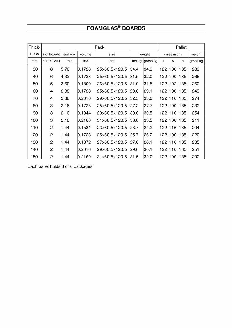
30 8 5.76 0.1728 25x60.5x120.5 34.4 34.9 122 100 135 289
40 6 4.32 0.1728 25x60.5x120.5 31.5 32.0 122 100 135 266
50 5 3.60 0.1800 26x60.5x120.5 31.0 31.5 122 102 135 262
60 4 2.88 0.1728 25x60.5x120.5 28.6 29.1 122 100 135 243
70 4 2.88 0.2016 29x60.5x120.5 32.5 33.0 122 116 135 274
80 3 2.16 0.1728 25x60.5x120.5 27.2 27.7 122 100 135 232
90 3 2.16 0.1944 29x60.5x120.5 30.0 30.5 122 116 135 254
100 3 2.16 0.2160 31x60.5x120.5 33.0 33.5 122 100 135 211
110 2 1.44 0.1584 23x60.5x120.5 23.7 24.2 122 116 135 204
120 2 1.44 0.1728 25x60.5x120.5 25.7 26.2 122 100 135 220
130 2 1.44 0.1872 27x60.5x120.5 27.6 28.1 122 116 135 235
140 2 1.44 0.2016 29x60.5x120.5 29.6 30.1 122 116 135 251
150 2 1.44 0.2160 31x60.5x120.5 31.5 32.0 122 100 135 202 Each pallet holds 8 or 6 packages

Pittsburgh Corning GmbH (Austria)
Pittsburgh Corning Nederland B.V.
Pittsburgh Corning Schweiz A.G.
FOAMGLAS® Península Ibérica
Pittsburgh Corning Scandinavia ab.
Deutsche Pittsburgh Corning GmbH
Pittsburgh Corning UK Ltd.
Pittsburgh Corning Norway
Pittsburgh Corning Italy
Pittsburgh Corning France S.A.
The innovative insulation people
Pittsburgh Corning Europe is also represented in: Croatia, Czech Republic, Denmark, Greece, Hungary, Poland, Rumania, Russian Federation, Slovak Republic, Slovenia, Ukraine and Africa.
A10
08/02
PREFABRICATED INSULATION IN SHELLS, SEGMENTS AND ELBOWS
FOAMGLAS® cellular glass shells and segments are available in a great variety of diameters and thicknesses. They correspond to the requirements of the user and allow a precise selection of the correct dimensions for the considered application.
The following documents show the great variety of elements prefabricated from FOAMGLAS® slabs. On top of these "standardised" elements, special pieces can be fabricated on request.
Document Prefabricated elements Diameter to be insulated in mm
from to
A11
Shells for straight pipes
13.5 244.5 - 368
A12
Segments for straight pipes
273 - 381 920
A13
Elbows
21.3 920
A14
Shells and segments for fittings
21.3 609.6
A15
Vessel segments
921 8000
A16
Vessel head segments
950 5000 and +
A17
Cone segments
450 20000
FACTS AND
FIGURES

A11-08/02 1/2
A11
08/02
1. NECESSARY DATA FOR FABRICATING FOAMGLAS® insulation will be prefabricated in shells up to an exterior diameter of 450 mm. If the exterior insulation diameter exceeds 450 mm, curved segments will be prefabricated (see A 12). 1.1. Dimensions of pipe to be insulated − pipe diameter − straight length − insulation thickness and number of layers 1.2. Service temperature Shells with a diameter up to 298.5 mm are fabricated from two monolithic pieces of FOAMGLAS® cellular glass. These shells are used in the whole service temperature range of the cellular glass (Fig.1)
150mmmax.
450 mm
Fig.1 Cutting of shells from a monolithic slab
Shells with an exterior diameter exceeding 298.5 mm have an adhesive joint since they are cut out of several preassembled cellular glass slabs (Fig.2). − If the temperature on the warm side of the
shells does not reach +120°C, the two slabs are adhered with hot bitumen,
− if the temperature of the shells exceeds +120°C, adhesion must be carried out by means of High Temperature Adhesive.
1. Hot bitumen t < +120°C or HT. Adhesive t > +120°C Fig.2 Cutting of shells from preassembled slabs
1.3. Anti-abrasive coating. Depending on service conditions, it will be applied to the inner surface of the FOAMGLAS® shells. The possible application of an anti-abrasive on site has to be indicated with the order since its application requires an increase of the interior diameter. Service temperature has to be indicated to apply the correct coating : 1.3.1. LOW TEMPERATURE ANTI-ABRASIVE for temperatures from -180 to +120°C. 1.3.2. PC® HIGH TEMPERATURE ANTI-ABRASIVE for high temperatures up to 350°C and temperatures lower than -180°C where inorganic materials are requested.
2. TOLERANCES Tolerances applied to FOAMGLAS® shells, they ensure a normal free movement between shells and the pipes :
− Inside shell diameter : 0 to 3 mm − Length : ± 2 mm − Thickness : ± 2 mm
PSH
SHELLS FOR STRAIGHT PIPES
Diameter from 13.5 to 244.5 - 368 mm

Pittsburgh Corning GmbH (Austria)
Pittsburgh Corning Nederland B.V.
Pittsburgh Corning Schweiz A.G.
FOAMGLAS® Península Ibérica
Pittsburgh Corning Scandinavia ab.
Deutsche Pittsburgh Corning GmbH
Pittsburgh Corning UK Ltd.
Pittsburgh Corning Norway
Pittsburgh Corning Italy
Pittsburgh Corning France S.A.
The innovative insulation people
Pittsburgh Corning Europe is also represented in: Croatia, Czech Republic, Denmark, Greece, Hungary, Poland, Rumania, Russian Federation, Slovak Republic, Slovenia, Ukraine and Africa.
3. DIMENSIONS OF PIPE SHELLS
FOAMGLAS® thicknesses and outside diameters (mm)
Diameter 1" 1 1/2" 2" 2 1/2" 3" 3 1/2" 4" of pipes FG OD FG OD FG OD FG OD FG OD FG OD FG OD
DN inch mm mm mm mm mm mm mm mm mm mm mm mm mm mm mm 8 1/4 13.5 31 76.1 37 88.9 50 114.3 63 139.7 77 168.3 90 193.7 102 219.1
10 3/8 17.2 29 76.1 42 101.6 55 127.0 61 139.7 75 168.3 88 193.7 100 219.1 15 1/2 21.3 27 76.1 40 101.6 52 127.0 68 159.0 85 193.7 98 219.1 111 244.5 20 3/4 26.9 24 76.1 37 101.6 50 127.0 65 159.0 83 193.7 96 219.1 108 244.5
30.0 29 88.9 42 114.3 54 139.7 69 168.3 81 193.7 94 219.1 107 244.5 25 1 33.7 27 88.9 40 114.3 53 139.7 67 168.3 80 193.7 92 219.1 105 244.5
38.0 25 88.9 38 114.3 50 139.7 65 168.3 77 193.7 90 219.1 103 244.5 32 1 1/4 42.4 23 88.9 42 127.0 48 139.7 62 168.3 75 193.7 88 219.1 101 244.5
44.5 28 101.6 41 127.0 47 139.7 61 168.3 74 193.7 87 219.1 99 244.5 40 1 1/2 48.3 26 101.6 39 127.0 54 159.0 72 193.7 85 219.1 97 244.5 111 273.0
51.0 25 101.6 38 127.0 53 159.0 70 193.7 83 219.1 96 244.5 110 273.0 57.0 28 114.3 41 139.7 50 159.0 68 193.7 81 219.1 93 244.5 108 273.0
50 2 60.3 27 114.3 39 139.7 54 168.3 66 193.7 79 219.1 92 244.5 106 273.0 70.0 28 127.0 44 159.0 49 168.3 61 193.7 74 219.1 87 244.5 101 273.0
65 2 1/2 76.1 25 127.0 41 159.0 58 193.7 71 219.1 83 244.5 98 273.0 110 298.5 80 3 88.9 25 139.7 39 168.3 52 193.7 65 219.1 77 244.5 92 273.0 104 298.5
3 1/2 101.6 33 168.3 46 193.7 57 219.1 71 244.5 85 273.0 98 298.5 111 323.9 108.0 30 168.3 42 193.7 55 219.1 68 244.5 82 273.0 94 298.5 107 323.9
100 4 114.3 27 168.3 39 193.7 52 219.1 65 244.5 79 273.0 92 298.5 104 323.9 4 1/2 127.0 33 193.7 46 219.1 58 244.5 73 273.0 85 298.5 98 323.9 114 355.6 133.0 30 193.7 42 219.1 55 244.5 69 273.0 82 298.5 95 323.9 111 355.6
125 5 139.7 26 193.7 39 219.1 52 244.5 66 273.0 78 298.5 91 323.9 107 355.6 159.0 29 219.1 42 244.5 56 273.0 69 298.5 82 323.9 98 355.6 110 381.0
150 6 168.3 25 219.1 37 244.5 52 273.0 64 298.5 77 323.9 93 355.6 106 381.0 7 193.7 39 273.0 51 298.5 64 323.9 80 355.6 93 381.0 106 406.4
200 8 219.1 39 298.5 52 323.9 67 355.6 80 381.0 93 406.4 106 431.8 9 244.5 39 323.9 55 355.6 67 381.0 80 406.4 93 431.8 100 445.0
250 10 273.0 40 355.6 53 381.0 66 406.4 79 431.8 88 450.0 11 298.5 41 381.0 53 406.4 66 431.8
300 12 323.9 41 406.4 53 431.8 350 14 355.6 37 431.8 47 450.0
368.0 40 449.0 Thicknesses are determined so that the outer diameter of a FOAMGLAS® shell always corresponds to the outside diameter of a standard pipe. This guarantees an adequate fitting of the successive insulation layers. The inside diameter of a FOAMGLAS® shell is equal to the outside diameter of a standard pipe, taking into account the corresponding ISO tolerances. Standard length (SL) Half shells for pipe insulation are furnished in "Standard Length" of 600 mm. The length to be insulated is divided by 0.6 and rounded off to the
half standard length, i.e. one half shell to be cut in two. Example Required length 80.5 m. Number of standard lengths : 80.5 m : 0.6 m/SL = 134.16 SL. When rounding off to the half standard length, we will obtain 134.5 standard length (SL). The furnished length will be : 134.5 SL x 0.6 m/SL = 80.7 m.
Monolithic piece With adhesive joint

A12-08/02 1/2
A12
08/02
1. NECESSARY DATA FOR FABRICATING Curved segments will be prefabricated if the outside insulation diameter exceeds 450 mm. FOAMGLAS® insulation shells will be prefabricated up to an outside diameter of 450 mm (see A11). 1.1. Dimensions of pipe to be insulated − pipe diameter − straight length − insulation thickness and number of layers 1.2. Service temperature The segments to be used at service temperatures above 120°C are cut out of one monolithic slab. The segments for lower temperatures are cut with a double ribbon saw from a pile of FOAMGLAS® slabs adhered with hot bitumen. Certain pieces will thus have a bituminous joint not in contact with the piping.
1.3. Anti-abrasive coating. Depending on service conditions, it will be applied to the inner surface of the FOAMGLAS® segments. The possible application of an anti-abrasive on site has to be indicated with the order since its application requires an increase of the interior diameter. Service temperature has to be indicated to apply the correct coating : 1.3.1. LOW TEMPERATURE ANTI-ABRASIVE for temperatures from -180 to +120°C. 1.3.2. PC® HIGH TEMPERATURE ANTI-ABRASIVE for high temperatures up to +350°C and temperatures lower than -180°C where inorganic materials are requested.
225 mm
600 mm
For temperatures < +120°Csegments cut out
of a pile of FOAMGLAS slabs
For temperatures > +120°Csegments cut out
of a monolithic FOAMGLAS slabs
Hot bitumen1
2
3
45
6
7
8
225 mm
600 mm
1
2
3
4
5
6
7
8
® ®
2. TOLERANCES Tolerances applied to FOAMGLAS® segments, they ensure a normal free movement between segments and the pipes :
− Curvature : ± 3 to 5 mm following the ∅ of the pipe − Thickness : ± 2 mm − Length : ± 2 mm − Width : ± 2 mm
PSG SEGMENTS FOR STRAIGHT PIPES
Diameter from 273-381 mm to 920 mm

Pittsburgh Corning GmbH (Austria)
Pittsburgh Corning Nederland B.V.
Pittsburgh Corning Schweiz A.G.
FOAMGLAS® Península Ibérica
Pittsburgh Corning Scandinavia ab.
Deutsche Pittsburgh Corning GmbH
Pittsburgh Corning UK Ltd.
Pittsburgh Corning Norway
Pittsburgh Corning Italy
Pittsburgh Corning France S.A.
The innovative insulation people
Pittsburgh Corning Europe is also represented in: Croatia, Czech Republic, Denmark, Greece, Hungary, Poland, Rumania, Russian Federation, Slovak Republic, Slovenia, Ukraine and Africa.
3. DIMENSIONS OF PIPE SEGMENTS
Diameter 40 mm 50 mm 60 mm 70 mm 80 mm 90 mm 100 mm of pipes segm/ outside segm/ outside segm/ outside segm/ outside segm/ outside segm/ outside segm/ outside
DN inch mm circumf. dia mm circumf. dia mm circumf. dia mm circumf. dia mm circumf. dia mm circumf. dia mm circumf. dia mm 250 10 273.0 353.0 7.0 473.0
11 298.5 379.0 6.5 459.0 7.0 479.0 7.0 499.0 300 12 323.9 404.0 6.5 444.0 6.5 464.0 7.0 484.0 7.0 504.0 7.5 524.0 350 14 355.6 436.0 6.5 456.0 7.0 476.0 7.0 496.0 7.5 516.0 7.5 536.0 8.0 556.0
368.0 448.0 6.5 468.0 7.0 488.0 7.5 508.0 7.5 528.0 8.0 548.0 8.0 568.0 15 381.0 6.5 461.0 7.0 481.0 7.0 501.0 7.5 521.0 8.0 541.0 8.0 561.0 8.5 581.0
400 16 406.4 7.0 486.0 7.5 506.0 7.5 526.0 8.0 546.0 8.0 566.0 8.5 586.0 8.5 606.0 419.0 7.0 499.0 7.5 519.0 7.5 539.0 8.0 559.0 8.5 579.0 8.5 599.0 9.0 619.0 17 431.8 7.5 512.0 7.5 532.0 8.0 552.0 8.0 572.0 8.5 592.0 9.0 612.0 9.0 632.0
450 18 457.2 7.5 537.0 8.0 557.0 8.5 577.0 8.5 597.0 9.0 617.0 9.0 637.0 9.5 657.0 470.0 8.0 550.0 8.0 570.0 8.5 590.0 8.5 610.0 9.0 630.0 9.5 650.0 9.5 670.0 19 482.6 8.0 563.0 8.5 583.0 8.5 603.0 9.0 623.0 9.0 643.0 9.5 663.0 9.5 683.0
500 20 508.0 8.5 588.0 8.5 608.0 9.0 628.0 9.5 648.0 9.5 668.0 10.0 688.0 10.0 708.0 521.0 8.5 601.0 9.0 621.0 9.0 641.0 9.5 661.0 9.5 681.0 10.0 701.0 10.5 721.0 21 533.4 9.0 613.0 9.0 633.0 9.5 653.0 9.5 673.0 10.0 693.0 10.0 713.0 10.5 733.0
550 22 558.8 9.0 639.0 9.5 659.0 9.5 679.0 10.0 699.0 10.0 719.0 10.5 739.0 11.0 759.0 570.0 9.5 650.0 9.5 670.0 10.0 690.0 10.0 710.0 10.5 730.0 10.5 750.0 11.0 770.0 23 584.2 9.5 664.0 10.0 684.0 10.0 704.0 10.5 724.0 10.5 744.0 11.0 764.0 11.0 784.0
600 24 609.6 10.0 690.0 10.0 710.0 10.5 730.0 10.5 750.0 11.0 770.0 11.0 790.0 11.5 810.0 622.0 10.0 702.0 10.5 722.0 10.5 742.0 11.0 762.0 11.0 782.0 11.5 802.0 11.5 822.0 25 635.0 10.0 715.0 10.5 735.0 11.0 755.0 11.0 775.0 11.5 795.0 11.5 815.0 12.0 835.0
650 26 660.4 10.5 740.0 11.0 760.0 11.0 780.0 11.5 800.0 11.5 820.0 12.0 840.0 12.0 860.0 27 685.8 11.0 766.0 11.0 786.0 11.5 806.0 11.5 826.0 12.0 846.0 12.5 866.0 12.5 886.0
700 28 711.2 11.5 791.0 11.5 811.0 12.0 831.0 12.0 851.0 12.5 871.0 12.5 891.0 13.0 911.0 720.0 11.5 800.0 11.5 820.0 12.0 840.0 12.0 860.0 12.5 880.0 13.0 900.0 13.0 920.0 29 736.6 11.5 817.0 12.0 837.0 12.0 857.0 12.5 877.0 12.5 897.0 13.0 917.0 13.5 937.0
750 30 762.0 12.0 842.0 12.0 862.0 12.5 882.0 13.0 902.0 13.0 922.0 13.5 942.0 13.5 962.0 31 787.4 12.5 867.0 12.5 887.0 13.0 907.0 13.0 927.0 13.5 947.0 13.5 967.0 14.0 987.0
800 32 812.8 12.5 893.0 13.0 913.0 13.0 933.0 13.5 953.0 14.0 973.0 14.0 993.0 14.5 1013.0 820.0 13.0 900.0 13.0 920.0 13.5 940.0 13.5 960.0 14.0 980.0 14.0 1000.0 14.5 1020.0 33 838.2 13.0 918.0 13.5 938.0 13.5 958.0 14.0 978.0 14.0 998.0 14.5 1018.0 14.5 1038.0 34 863.6 13.5 944.0 13.5 964.0 14.0 984.0 14.0 1004.0 14.5 1024.0 15.0 1044.0 15.0 1064.0 35 889.0 13.5 969.0 14.0 989.0 14.5 1009.0 14.5 1029.0 15.0 1049.0 15.0 1069.0 15.5 1089.0
900 36 914.4 14.0 994.0 14.5 1014.0 14.5 1034.0 15.0 1054.0 15.0 1074.0 15.5 1094.0 16.0 1114.0 920.0 14.0 1000.0 14.5 1020.0 14.5 1040.0 15.0 1060.0 15.5 1080.0 15.5 1100.0 16.0 1120.0
By using thicknesses that are graded by a factor of ten, we obtain "non-standard" exterior diameters. For the calculation of a second insulation layer the nearest larger diameter will be chosen. Standard Length (SL) The segments have a length of 600 mm. The length of the pipe to be insulated will be divided by 0.6 to determine the number of Standard Lengths. The number will be rounded off to furnished half-lengths. Example : see half shells A11. Number of segments per circumference (Fig.1). All segments have an exterior width of 225 mm. The number necessary per circumference, per Standard Length, is rounded up to the next half unit.
225 mm
Fig.1 Last segment will be adjusted.
The last segment of the circumference will have to be adjusted during application, and the cut off exceeding 110 mm to be reused.

A13-08/02 1/2
A13
08/02
1. NECESSARY DATA FOR FABRICATING FOAMGLAS® elbows have a curvature where R = 1.5 D (type 3D) and can be furnished in the same thicknesses as shells and segments for straight pipes. 1.1. Dimensions of elbows to be insulated − pipe diameter − if different from standard (90°, R = 1.5 D,
type 3 D) : angle and curvature radius. − insulation thickness and number of layers − number of elbows. 1.2. Service temperature FOAMGLAS® elbows with an exterior diameter up to 298.5 mm are fabricated from 2 monolithic cellular glass pieces. These shells can be used at any temperature for which the cellular glass is specified (Fig.1).
90°R=1.5 x D
D
Fig.1 Two monolithic pieces
FOAMGLAS® elbows with an exterior diameter exceeding 298.5 mm are preassembled with the adequate adhesive. If temperature on the warm side does not reach +120°C, they will be adhered with hot bitumen. If temperature on the warm side exceeds +120°C, adhesion must be carried out with High Temperature Adhesive.
12
3
490°
Fig.2 Preassembled elbow
1.3. Anti-abrasive coating. Depending on service conditions, it will be applied to the inner surface of the FOAMGLAS® elbows. The possible application of an anti-abrasive on site has to be indicated with the order since its application requires an increase of the interior diameter.Service temperature has to be indicated to apply the correct coating. 1.3.1. LOW TEMPERATURE ANTI-ABRASIVE for temperatures from -180 to +120°C. 1.3.2. PC® HIGH TEMPERATURE ANTI-ABRASIVE for high temperatures up to +350°C and temperatures lower than -180°C where inorganic materials are requested.
2. TOLERANCES FOAMGLAS® elbows : − Inside diameter :
≤ 273 mm : 0 to 3 mm > 273 mm : 0 to 5 mm
− Curvature radius : ≤ 371 mm : ± 3 mm > 371 mm : ± 5 mm
− Insulation thickness : ± 2 mm
E90 E45
ELBOWS
Diameter from 21.3 mm to 920 mm

3. DIMENSIONS OF ELBOWS The thickness tables as detailed for the insulation of straight pipes with shells and segments are applicable (see documents A 11 and A 12). This guarantees a good connection between the different insulation elements. One single insulation layer is normally applied if thickness is below or equal to 100 mm since no staggering of joints is possible between layers. The curvature radius normally used is equal to one and a half diameter. These elbows are also called
type 3D. (The rule R = 1.5 D applies to the diameter in inches). P.S. Elbows with an exterior diameter up to 298.5 mm can be cut to a different curvature radius. Cutting on site (Fig.3 and table) Cutting on site of elbows for large diameters can be made from half shells or segments for straight pipes. When using segments, it is important to assemble them in half shells that cover exactly half the circumference.
1 2 3 4 5 6 7 8 9 10 11 12/212/1180°
Fig.3 Example 323.9 mm / 12" x 50 mm
88 mm 45 mm
90°
12/1 1 2 34
56
7
8
9
10
1112/2
The table below has been conceived for large elbows type 3D (R = 1.5 D).
Diameter 40 mm 50 mm 60 mm 70 mm 80 mm 90 mm 100 mm of elbow
DN inch mm N A B A B A B A B A B A B A B 250 10 273.0 11 80 41 81 42 82 43 84 45 85 46 87 48 88 49
11 298.5 11 87 44 88 46 90 47 91 49 93 50 94 51 95 53 300 12 323.9 12 86 44 88 45 89 47 90 48 92 49 93 50 94 52350 14 355.6 12 98 52 100 53 101 54 102 56 104 57 105 58 106 60
368.0 13 94 49 95 51 96 52 97 53 99 54 100 55 101 57 15 381.0 13 97 51 98 52 99 53 101 54 102 56 103 57 104 58
400 16 406.4 13 103 54 104 55 105 56 107 58 108 59 109 60 110 61 419.0 14 99 52 100 53 101 54 102 55 103 56 104 57 105 58 17 431.8 14 101 53 103 54 104 55 105 56 106 57 107 59 108 60
450 18 457.2 14 107 56 108 57 109 58 110 59 112 60 113 61 114 63 470.0 14 110 57 111 58 112 59 113 61 114 62 116 63 117 64
19 482.6 14 113 59 114 60 115 61 116 62 117 63 118 64 120 65 500 20 508.0 15 111 57 112 58 113 59 114 61 115 62 116 63 117 64
521.0 15 113 59 114 60 115 61 116 62 117 63 118 64 120 65 21 533.4 15 116 60 117 61 118 62 119 63 120 64 121 65 122 66
550 22 558.8 16 114 59 115 60 116 61 117 62 118 63 119 64 120 65 570.0 16 116 60 117 61 118 62 119 63 120 64 121 65 122 66 23 584.2 16 119 61 120 62 121 63 122 64 123 65 124 66 125 67
600 24 609.6 16 124 64 125 65 126 66 127 67 128 68 129 69 130 70 622.0 16 126 65 127 66 128 67 129 68 130 69 131 70 132 71
25 635.0 17 121 62 122 63 123 64 124 65 125 66 126 67 127 68650 26 660.4 17 126 65 127 66 128 67 129 67 129 68 130 69 131 70
27 685.8 17 130 67 131 68 132 69 133 70 134 71 135 72 136 73 700 28 711.2 17 135 69 136 70 137 71 138 72 139 73 140 74 141 75
720.0 18 129 67 130 67 131 68 132 69 133 70 134 71 135 72 29 736.6 18 132 68 133 69 134 70 135 70 136 71 136 72 137 73
750 30 762.0 18 136 70 137 71 138 72 139 73 140 73 141 74 142 75 31 787.4 18 141 72 142 73 143 74 144 75 144 76 145 77 146 77
800 32 812.8 19 138 71 139 71 139 72 140 73 141 74 142 75 143 75 820.0 19 139 71 140 72 141 73 141 74 142 74 143 75 144 76
33 838.2 19 142 73 143 73 144 74 144 75 145 76 146 77 147 78 34 863.6 19 146 75 147 76 148 76 149 77 149 78 150 79 151 80 35 889.0 20 143 73 144 74 144 75 145 75 146 76 147 77 147 78
900 36 914.4 20 147 75 148 76 148 77 149 77 150 78 151 79 151 80 920.0 20 148 75 148 76 149 77 150 78 151 76 152 79 152 80
Pittsburgh Corning GmbH (Austria)
Pittsburgh Corning Nederland B.V.
Pittsburgh Corning Schweiz A.G.
FOAMGLAS® Península Ibérica
Pittsburgh Corning Scandinavia ab.
Deutsche Pittsburgh Corning GmbH
Pittsburgh Corning UK Ltd.
Pittsburgh Corning Norway
Pittsburgh Corning Italy
Pittsburgh Corning France S.A.
The innovative insulation people
Pittsburgh Corning Europe is also represented in: Croatia, Czech Republic, Denmark, Greece, Hungary, Poland, Rumania, Russian Federation, Slovak Republic, Slovenia, Ukraine and Africa.

A14.1-08/02 1/2
A14.1
08/02
1. NECESSARY DATA FOR FABRICATING 1.1. Dimensions of flange to be insulated − diameter of connected pipe − number of flanges − insulation thickness and number of layers − nominal pressure and type of flange or:
− exterior diameter of flange − total length, including tightening bolts
1.2. Service temperature Service temperature should be indicated so as to allow factory to choose the best adapted fabrication method for adhesion on site.
1.3. Anti-abrasive coating. Depending on service conditions, it can be applied to the part which will be in contact with the pipe, i.e. packing pieces (dutchman). Service temperature has to be indicated to apply the correct coating. 1.3.1. LOW TEMPERATURE ANTI-ABRASIVE for temperatures from -180 to +120°C. 1.3.2. PC® HIGH TEMPERATURE ANTI-ABRASIVE for high temperatures up to 350°C and temperatures lower than -180°C where inorganic materials are requested.
2. TOLERANCES Tolerances applied to FOAMGLAS® shells, they ensure a normal free movement between shells and the pipes :
− Inside shell diameter : 0 to 5 mm − Length : ± 2 mm − Thickness : ± 2 mm − Width : ± 2 mm
3. HOW TO APPLY FOAMGLAS® FLANGE INSULATION. Example : Pipe diameter 4” (114.3 mm), Flange class 150, FOAMGLAS® thickness 2” Material delivered A : 1 half shell of 600 mm
type PSH 4” x 2 ½”, to be cut in 4 pieces of 150 mm for the packing piece (dutchman)
B : 2 half shells of 600
mm type PSH 9” x 2”, to be applied over the dutchman and to be adjusted in length
F15 F30
FLANGES
Diameter from 21.3 to 609.6 mm

4. DIMENSIONS OF FLANGE INSULATION
Class 150 Pipe diameter Flange FOAMGLAS® packing piece
FOAMGLAS® flange insulation
Type F15 dia length thickness length inside diameter length
DN Inch mm mm mm inch mm m inch mm m 15 ½ 21.3 89 48 1 ½ 40 0.3 3 ½ 101.6 0.6 20 ¾ 26.9 99 53 1 ½ 37 0.3 3 ½ 101.6 0.6 25 1 33.7 108 56 1 ½ 40 0.3 4 114.3 0.6 32 1 ¼ 42.4 118 57 1 ½ 42 0.3 4 ½ 127.0 0.6 40 1 ½ 48.3 127 62 1 ½ 39 0.3 4 ½ 127.0 0.6 50 2 60.3 153 64 2 54 0.3 6 168.3 0.6 65 2 ½ 76.1 178 70 2 58 0.3 7 193.7 0.6 80 3 88.9 191 70 2 52 0.3 7 193.7 0.6
Example 100 4 114.3 229 76 2 ½ 65 0.3 9 244.5 0.6125 5 139.7 254 89 2 ½ 66 0.3 10 273.0 0.6 150 6 168.3 280 89 2 ½ 64 0.3 11 298.5 0.6 200 8 219.1 343 102 2 ½ 67 0.3 14 355.6 0.6 250 10 273.0 407 102 2 ½ 66 0.3 16 406.4 0.6 300 12 323.9 483 114 80 0.3 19 482.6 0.6 350 14 355.6 534 127 90 0.3 21 533.4 0.6 400 16 406.4 597 127 100 0.3 24 609.6 0.6 450 18 457.2 635 140 100 0.3 26 660.4 0.6 500 20 508.0 699 145 100 0.3 28 711.2 0.6 600 24 609.6 813 152 100 0.3 32 812.8 0.9
Class 300 Pipe diameter Flange FOAMGLAS® packing piece
FOAMGLAS® flange insulation
Type F30 dia length thickness length inside diameter length
DN Inch mm mm mm inch mm m inch mm m 15 ½ 21.3 96 53 1 ½ 40 0.3 3 ½ 101.6 0.620 ¾ 26.9 118 57 2 50 0.3 4 ½ 127.0 0.6 25 1 33.7 124 62 2 53 0.3 5 139.7 0.6 32 1 ¼ 42.4 134 65 2 48 0.3 5 139.7 0.6 40 1 ½ 48.3 156 69 2 54 0.3 159.0 0.650 2 60.3 165 70 2 54 0.3 6 168.3 0.6 65 2 ½ 76.1 191 77 2 58 0.3 7 193.7 0.6 80 3 88.9 210 80 2 ½ 65 0.3 8 219.1 0.6
100 4 114.3 254 86 3 79 0.3 10 273.0 0.6125 5 139.7 280 99 3 78 0.3 11 298.5 0.6 150 6 168.3 318 99 3 77 0.3 12 323.9 0.6 200 8 219.1 381 112 3 80 0.3 15 381.0 0.6 250 10 273.0 445 118 3 ½ 88 0.3 18 457.2 0.6300 12 323.9 521 131 100 0.3 21 533.4 0.6 350 14 355.6 585 143 60+50 0.3 23 584.2 0.6 400 16 406.4 648 146 80+50 0.3 27 685.8 0.6 450 18 457.2 712 159 80+50 0.3 726.0 0.9500 20 508.0 775 162 80+60 0.3 31 787.4 0.9 600 24 609.6 915 169 80+80 0.3 930.0 0.9
Pittsburgh Corning GmbH (Austria)
Pittsburgh Corning Nederland B.V.
Pittsburgh Corning Schweiz A.G.
FOAMGLAS® Península Ibérica
Pittsburgh Corning Scandinavia ab.
Deutsche Pittsburgh Corning GmbH
Pittsburgh Corning UK Ltd.
Pittsburgh Corning Norway
Pittsburgh Corning Italy
Pittsburgh Corning France S.A.
The innovative insulation people
Pittsburgh Corning Europe is also represented in: Croatia, Czech Republic, Denmark, Greece, Hungary, Poland, Rumania, Russian Federation, Slovak Republic, Slovenia, Ukraine and Africa.

A14.2-08/02 1/2
A14.2
08/02
1. NECESSARY DATA FOR FABRICATING 1.1. Dimensions of valve to be insulated − diameter of connected pipe − number of valves − insulation thickness and number of layers − nominal pressure and type of valve or:
− exterior diameter of flanged valve − total length, including tightening bolts − height of valve
1.2. Service temperature Service temperature should be indicated so as to allow factory to choose the best adapted fabrication method for adhesion on site.
1.3. Anti-abrasive coating. Depending on service conditions, it can be applied to the part which will be in contact with the pipe, i.e. packing pieces (dutchman). Service temperature has to be indicated to apply the correct coating : 1.3.1. LOW TEMPERATURE ANTI-ABRASIVE for temperatures from -180 to +120°C. 1.3.2. PC® HIGH TEMPERATURE ANTI-ABRASIVE for high temperatures up to 350°C and temperatures lower than -180°C where inorganic materials are requested.
2. TOLERANCES Tolerances applied to FOAMGLAS® shells, they ensure a normal free movement between shells and the pipes :
− Inside shell diameter : 0 to 5 mm − Length : ± 2 mm − Thickness : ± 2 mm − Width : ± 2 mm
3. HOW TO APPLY FOAMGLAS® VALVE INSULATION Example: Pipe diameter 3” (88.9 mm), Valve class 150,
FOAMGLAS® thickness 2”
Material delivered: A : 1 half shell of 600 mm type PSH 3” x 2”,
to be cut in 4 pieces of 150 mm for the packing piece (dutchman) B : 4 half shells of 600 mm type PSH 7” x 2”,
B1 : to be cut at 45° and adjusted in length (1half shell) B2 : to be adjusted in length and placed at the bottom (1 half shell) B3 : to be cut at 45° and adjusted in length (2 half shells)
C: 1 flat block of
300 x 450 x 50 mm to be cut in 2 and adjusted around spindle
V15 V30
VALVES
Diameter from 48.3 to 609.6 mm
A
B1 B1
B2
B3 B3C
45°

Pittsburgh Corning GmbH (Austria)
Pittsburgh Corning Nederland B.V.
Pittsburgh Corning Schweiz A.G.
FOAMGLAS® Península Ibérica
Pittsburgh Corning Scandinavia ab.
Deutsche Pittsburgh Corning GmbH
Pittsburgh Corning UK Ltd.
Pittsburgh Corning Norway
Pittsburgh Corning Italy
Pittsburgh Corning France S.A.
The innovative insulation people
Pittsburgh Corning Europe is also represented in: Croatia, Czech Republic, Denmark, Greece, Hungary, Poland, Rumania, Russian Federation, Slovak Republic, Slovenia, Ukraine and Africa.
4. DIMENSIONS OF VALVE INSULATION
Class 150 Pipe diameter Valve FOAMGLAS® packing piece
FOAMGLAS® valve insulation
Type V15 dia length thickness length inside diameter length
DN Inch mm mm mm inch mm m inch mm m 40 1 ½ 48.3 127 178 1 ½ 39 0.3 4 ½ 127.0 0.9 50 2 60.3 153 191 2 54 0.3 6 168.3 0.9 65 2 ½ 76.1 178 203 2 58 0.3 7 193.7 1.2
Example 80 3 88.9 191 216 2 52 0.3 7 193.7 1.2 100 4 114.3 229 241 2 ½ 65 0.3 9 244.5 1.2 125 5 139.7 254 267 2 ½ 66 0.3 10 273.0 1.2 150 6 168.3 280 279 2 ½ 64 0.3 11 298.5 1.2 200 8 219.1 343 305 2 ½ 67 0.3 14 355.6 1.5 250 10 273.0 407 343 2 ½ 66 0.3 16 406.4 1.5 300 12 323.9 483 368 80 0.3 19 482.6 1.5 350 14 355.6 534 394 90 0.3 21 533.4 1.5 400 16 406.4 597 419 100 0.3 24 609.6 1.8 450 18 457.2 635 445 100 0.3 26 660.4 1.8 500 20 508.0 699 470 100 0.3 28 711.2 1.8 600 24 609.6 813 521 100 0.3 32 812.8 2.1
Class 300 Pipe diameter Valve FOAMGLAS® packing piece
FOAMGLAS® valve insulation
Type V30 dia length thickness length inside diameter length
DN Inch mm mm mm inch mm m inch mm m 40 1 ½ 48.3 156 203 2 54 0.3 159.0 1.2 50 2 60.3 165 232 2 54 0.3 6 168.3 1.2 65 2 ½ 76.1 191 257 2 58 0.3 7 193.7 1.2 80 3 88.9 210 298 2 ½ 65 0.3 8 219.1 1.2
100 4 114.3 254 321 3 79 0.3 10 273.0 1.5 125 5 139.7 280 397 3 78 0.3 11 298.5 1.5 150 6 168.3 318 419 3 77 0.3 12 323.9 1.8 200 8 219.1 381 435 3 80 0.3 15 381.0 1.8 250 10 273.0 445 473 3 ½ 88 0.3 18 457.2 1.8 300 12 323.9 521 518 100 0.3 21 533.4 2.1 350 14 355.6 585 778 60+50 0.3 23 584.2 2.7 400 16 406.4 648 854 80+50 0.3 27 685.8 3.0 450 18 457.2 712 930 80+50 0.3 726.0 3.3 500 20 508.0 775 1010 80+60 0.3 31 787.4 3.6 600 24 609.6 915 1114 80+80 0.3 930.0 3.9

A15-08/02 1/2
A15
08/02
1. NECESSARY DATA FOR FABRICATING As for large diameter pipes, these segments are also prefabricated to be applied to the cylindrical vessel walls. 1.1. Dimensions of vessel to be insulated − exterior vessel diameter − insulation thickness and number of layers − length of cylindrical part to be insulated 1.2. Service temperature The service temperature must be indicated to allow the factory to choose the most adaptable prefabrication method. The segments foreseen for a use at service temperatures above 120°C are cut out of one monolithic slab. The segments for lower temperatures are cut with a double ribbon saw from a pile of FOAMGLAS® slabs adhered with hot bitumen. Certain pieces will thus have a bituminous joint that is not in contact with the piping. (Fig.1 and Fig.2) 1.3. Anti-abrasive coating. Depending on service conditions, it will be applied to the inner surface of the FOAMGLAS® segments.
Service temperature has to be indicated to apply the correct coating : 1.3.1. LOW TEMPERATURE ANTI-ABRASIVE for temperatures from -180 to +120°C. 1.3.2. PC® HIGH TEMPERATURE ANTI-ABRASIVE for high temperatures up to +350°C and temperatures lower than -180°C where inorganic materials are requested.
295 mm
450 mm
Fig.2 Temperatures > 120°C
600 mm
220 mm445 mm
hot bitumen
Fig.1 Temperatures < 120°C
2. TOLERANCES FOAMGLAS® vessel segments : Curvature : ± 5 mm Thickness : ± 2 mm Length : ± 2 mm Width : ± 2 mm
TSG
VESSEL SEGMENTS
Diameter from 900 mm to 8000 mm and more

3. DIMENSIONS OF VESSEL SEGMENTS Dimensions of vessel segments supplied by Pittsburgh Corning Thicknesses 40 - 50 - 60 - 70 - 80 - 90 - 100 mm Width and length of segments Low temperature application : Vessel diameter from 920 to 3000 mm segments of 220 x 600 mm Vessel diameter from 3000 to 8000 mm segments of 445 x 600 mm High temperature application: Vessel diameters between 920 and 8000 mm monolithic segments 295 x 450 mm On site fabrication When the vessel diameter exceeds 3 m and service temperature exceeds ambient temperature, the segments can be cut out of flat slabs. This operation will be limited by two factors :
− The maximum deflection between flat FOAMGLAS® slab and curved wall.
− The joint opening between cut slab and right angle.
Maximum deflection. The following table has been elaborated to limit the theoretical deflection to a maximum of 2 mm (Fig.3). Width of flat Minimum diameter of FOAMGLAS® slab cylindrical vessel mm mm 150 3000 225 7000 300 12000 450 25000
R R'
a
b
b ≅ R' - R
R' = R a2 2+ Fig.3 Maximum deflection Axial joint opening. It is recommended to limit the opening(x) to 3 mm at the outside. To achieve this, at least the longitudinal sides should be bevelled in most cases (Fig.4).
R
X
da
xd2
= a R
x 2a x dR
≅
Fig.4 Axial opening
Pittsburgh Corning GmbH (Austria)
Pittsburgh Corning Nederland B.V.
Pittsburgh Corning Schweiz A.G.
FOAMGLAS® Península Ibérica
Pittsburgh Corning Scandinavia ab.
Deutsche Pittsburgh Corning GmbH
Pittsburgh Corning UK Ltd.
Pittsburgh Corning Norway
Pittsburgh Corning Italy
Pittsburgh Corning France S.A.
The innovative insulation people
Pittsburgh Corning Europe is also represented in: Croatia, Czech Republic, Denmark, Greece, Hungary, Poland, Rumania, Russian Federation, Slovak Republic, Slovenia, Ukraine and Africa.

A16-08/02 1/2
A16
08/02
1. NECESSARY DATA FOR FABRICATING For the insulation of vessel heads Pittsburgh Corning offers segments for the insulation of dished heads (HEH) (R = D and r = 0.1 D) and basket heads (HKH) (R = 0.8 D and r = 0.154 D). 1.1. Dimensions of vessel head to be insulated − exterior vessel diameter − greater radius of head or curvature radius − small radius of head or knuckle radius − insulation thickness and number of layers 1.2. Service temperature Segments for spherical heads (SHS) are fabricated from a monolithic FOAMGLAS® cellular glass slab, they are used in the whole service temperature range of FOAMGLAS® cellular glass (Fig.1).
Rr
Fig.1 Spherical head segments for central part (Type SHS)
Segments for the small radius (SRS) (Fig.2) are precut from curved segments for straight pipe and assembled with bitumen at the factory or by means of HT Adhesive on site depending on temperature.
If the temperature on the warm side of the segments does not reach +120°C, the two parts are adhered with hot bitumen. If the temperature of the segments exceeds 120°C, adhesion must be carried out by means of High Temperature Adhesive.
R
r
1. Hot bitumen t < +120°C or H.T. Adhesive t > +120°C Fig.2 Small radius segment (Type SRS)
1.3. Anti-abrasive coating. Depending on service conditions, it will be applied to the inner surface of the FOAMGLAS® segments. Service temperature has to be indicated to apply the correct coating : 1.3.1. LOW TEMPERATURE ANTI-ABRASIVE for temperatures from -180 to +120°C. 1.3.2. PC® HIGH TEMPERATURE ANTI-ABRASIVE for high temperatures up to +350°C and temperatures lower than -180°C where inorganic materials are requested.
2. TOLERANCES Tolerances that apply to FOAMGLAS® vessel head segments : Curvature : ± 3 to ± 5 mm depending on radius
Thickness : ± 2 mm Length : ± 2 mm Width : ± 2 mm
HEH HKH
HEAD SEGMENTS
Diameter from 750 mm to 5000 mm and more

3. DIMENSIONS OF HEAD SEGMENTS Dimensions of head segments supplied by Pittsburgh Corning Thicknesses 40 - 50 - 60 - 70 - 80 - 90 - 100 mm
Width and length of segments for central part (Fig.3).
Radius Dimensions of of curvature segments mm mm 750 to 900 215 x 295 901 to 5000 295 x 440
Fig.3 SHS segment
Dimensions of segments for small radius (Fig.4). Width at the base : 145 mm Covered section of circle : ± 60°
max. 145 mm
± 60°
Fig.4 SRS segment
4. SIMPLIFIED CALCULATION OF NUMBER OF PIECESDished head HEH
R = D r = 0.10 x D
Number of spherical segments for central part SHS :
N = 5.35 x OD²
For curvature radius from 750 up to 900 mm multiply number of segments by 2.
Number of segments for smaller radius for the connection to the cylindrical wall SRS :
N = 22.1 x OD
OD = Cylindrical vessel diameter + 2 x insulation thickness, i.e. exterior insulation diameter in meters.
Basket head HKH
R = 0.8 D r = 0.154 x D
Number of spherical segments for central part SHS :
N = 5.10 x OD²
For curvature radius from 750 up to 900 mm multiply number of segments by 2.
Number of segments for smaller radius for the connection to the cylindrical wall SRS :
N = 22.1 x OD
OD = Cylindrical vessel diameter + 2 x insulation thickness, i.e. exterior insulation diameter in meters.
SHS SRS
r
R
Pittsburgh Corning GmbH (Austria)
Pittsburgh Corning Nederland B.V.
Pittsburgh Corning Schweiz A.G.
FOAMGLAS® Península Ibérica
Pittsburgh Corning Scandinavia ab.
Deutsche Pittsburgh Corning GmbH
Pittsburgh Corning UK Ltd.
Pittsburgh Corning Norway
Pittsburgh Corning Italy
Pittsburgh Corning France S.A.
The innovative insulation people
Pittsburgh Corning Europe is also represented in: Croatia, Czech Republic, Denmark, Greece, Hungary, Poland, Rumania, Russian Federation, Slovak Republic, Slovenia, Ukraine and Africa.

A40-08/02 1/4
A40
08/02
1. PIPE SHELLS - TYPE PSH
1" 1 1/2" 2" 2 1/2" 3" 3 1/2" 4"
DIAMETER inside FG joint outside FG joint outside FG joint outside FG joint outside FG joint outside FG joint outside FG joint outside
DN inch mm m²/lm mm m²/lm m²/lm mm m²/lm m²/lm mm m²/lm m²/lm mm m²/lm m²/lm mm m²/lm m²/lm mm m²/lm m²/lm mm m²/lm m²/lm
8 1/4 13.5 0.042 31 0.069 0.237 37 0.084 0.275 50 0.117 0.357 63 0.151 0.438 77 0.190 0.526 90 0.229 0.608 102 0.266 0.683
10 3/8 17.2 0.054 29 0.065 0.236 42 0.097 0.318 55 0.131 0.400 61 0.147 0.437 75 0.186 0.525 88 0.224 0.607 100 0.261 0.682
15 1/2 21.3 0.067 27 0.061 0.237 40 0.093 0.318 52 0.124 0.394 68 0.168 0.494 85 0.217 0.601 98 0.257 0.683 111 0.299 0.764
20 3/4 26.9 0.085 24 0.054 0.235 37 0.086 0.317 50 0.120 0.399 65 0.161 0.493 83 0.214 0.606 96 0.254 0.688 108 0.292 0.763
30.0 0.094 29 0.067 0.276 42 0.100 0.358 54 0.132 0.434 69 0.174 0.528 81 0.209 0.603 94 0.249 0.685 107 0.291 0.767
25 1 33.7 0.106 27 0.063 0.276 40 0.095 0.357 53 0.130 0.439 67 0.169 0.527 80 0.208 0.609 92 0.245 0.684 105 0.286 0.766
38.0 0.119 25 0.058 0.276 38 0.091 0.358 50 0.123 0.434 65 0.165 0.528 77 0.200 0.603 90 0.240 0.685 103 0.282 0.767
32 1 1/4 42.4 0.133 23 0.054 0.278 42 0.103 0.397 48 0.119 0.435 62 0.158 0.523 75 0.196 0.604 88 0.236 0.686 101 0.278 0.768
44.5 0.140 28 0.067 0.316 41 0.100 0.397 47 0.117 0.435 61 0.156 0.523 74 0.194 0.605 87 0.234 0.686 99 0.272 0.762
40 1 1/2 48.3 0.152 26 0.062 0.315 39 0.096 0.397 54 0.137 0.491 72 0.189 0.604 85 0.229 0.686 97 0.268 0.761 111 0.315 0.849
51.0 0.160 25 0.060 0.317 38 0.094 0.399 53 0.135 0.493 70 0.184 0.600 83 0.224 0.682 96 0.266 0.763 110 0.313 0.851
57.0 0.179 28 0.068 0.355 41 0.103 0.437 50 0.128 0.493 68 0.181 0.606 81 0.221 0.688 93 0.259 0.763 108 0.309 0.858
50 2 60.3 0.189 27 0.066 0.359 39 0.098 0.434 54 0.140 0.529 66 0.176 0.604 79 0.216 0.686 92 0.257 0.767 106 0.304 0.855
70.0 0.220 28 0.070 0.396 44 0.114 0.496 49 0.129 0.528 61 0.164 0.603 74 0.204 0.685 87 0.246 0.767 101 0.292 0.855
65 2 1/2 76.1 0.239 25 0.063 0.396 41 0.107 0.497 58 0.157 0.603 71 0.197 0.685 83 0.235 0.761 98 0.285 0.855 110 0.327 0.930
80 3 88.9 0.279 25 0.065 0.436 39 0.104 0.524 52 0.142 0.606 65 0.182 0.688 77 0.221 0.763 92 0.271 0.857 104 0.313 0.933
3 1/2 101.6 0.319 33 0.089 0.527 46 0.128 0.608 57 0.161 0.677 71 0.206 0.765 85 0.253 0.853 98 0.298 0.935 111 0.346 1.017
108.0 0.339 30 0.082 0.528 42 0.117 0.603 55 0.157 0.685 68 0.199 0.767 82 0.246 0.855 94 0.287 0.930 107 0.334 1.012
100 4 114.3 0.359 27 0.074 0.529 39 0.109 0.604 52 0.149 0.686 65 0.191 0.767 79 0.238 0.855 92 0.283 0.937 104 0.327 1.013
4 1/2 127.0 0.399 33 0.094 0.606 46 0.134 0.688 58 0.172 0.763 73 0.222 0.858 85 0.264 0.933 98 0.311 1.015 114 0.372 1.115
133.0 0.418 30 0.086 0.606 42 0.122 0.682 55 0.164 0.763 69 0.211 0.851 82 0.256 0.933 95 0.303 1.015 111 0.364 1.115
125 5 139.7 0.439 26 0.075 0.602 39 0.114 0.684 52 0.156 0.766 66 0.203 0.854 78 0.245 0.929 91 0.292 1.011 107 0.352 1.111
159.0 0.500 29 0.087 0.682 42 0.128 0.763 56 0.175 0.851 69 0.220 0.933 82 0.267 1.015 98 0.328 1.115 110 0.375 1.191
150 6 168.3 0.529 25 0.075 0.686 37 0.114 0.761 52 0.164 0.855 64 0.206 0.931 77 0.253 1.013 93 0.313 1.113 106 0.364 1.195
7 193.7 0.609 39 0.126 0.854 51 0.167 0.929 64 0.214 1.011 80 0.275 1.111 93 0.326 1.193 106 0.378 1.275
200 8 219.1 0.688 39 0.131 0.933 52 0.178 1.015 67 0.234 1.109 80 0.285 1.191 93 0.338 1.273 106 0.392 1.354
9 244.5 0.768 39 0.136 1.013 55 0.196 1.114 67 0.243 1.189 80 0.296 1.271 93 0.350 1.352 100 0.380 1.396
250 10 273.0 0.858 40 0.146 1.109 53 0.196 1.191 66 0.249 1.272 79 0.304 1.354 88 0.342 1.411
11 298.5 0.938 41 0.155 1.195 53 0.204 1.271 66 0.258 1.352
300 12 323.9 1.018 41 0.160 1.275 53 0.211 1.351
350 14 355.6 1.117 37 0.150 1.350 47 0.193 1.412
368.0 1.156 40 0.165 1.407
INSIDE OUTSIDE
JOINT SURFACES

2/4 A40-08/02
2. ELBOWS 90° - TYPE E90
1" 1 1/2" 2" 2 1/2" 3" 3 1/2" 4"
DIAMETER inside FG joint outside FG joint outside FG joint outside FG joint outside FG joint outside FG joint outside FG joint outside
DN inch mm m²/pc mm m²/pc m²/pc mm m²/pc m²/pc mm m²/pc m²/pc mm m²/pc m²/pc mm m²/pc m²/pc mm m²/pc m²/pc mm m²/pc m²/pc
15 1/2 21.3 0.0034 27 0.0069 0.0119 40 0.0118 0.0160 52 0.0175 0.0198 68 0.0263 0.0248 85 0.0376 0.0302 98 0.0472 0.0343 111 0.0577 0.0384
20 3/4 26.9 0.0054 24 0.0070 0.0149 37 0.0122 0.0201 50 0.0184 0.0253 65 0.0275 0.0312 83 0.0394 0.0384 96 0.0493 0.0436 108 0.0601 0.0484
30.0 0.0067 29 0.0096 0.0195 42 0.0155 0.0253 54 0.0223 0.0306 69 0.0313 0.0373 81 0.0402 0.0426 94 0.0503 0.0484 107 0.0614 0.0542
25 1 33.7 0.0084 27 0.0096 0.0219 40 0.0157 0.0284 53 0.0229 0.0348 67 0.0320 0.0418 80 0.0413 0.0483 92 0.0514 0.0543 105 0.0627 0.0608
38.0 0.0107 25 0.0095 0.0248 38 0.0159 0.0321 50 0.0231 0.0388 65 0.0328 0.0473 77 0.0421 0.0540 90 0.0527 0.0613 103 0.0643 0.0686
32 1 1/4 42.4 0.0133 23 0.0094 0.0277 42 0.0196 0.0397 48 0.0235 0.0434 62 0.0332 0.0522 75 0.0430 0.0604 88 0.0539 0.0685 101 0.0657 0.0767
44.5 0.0147 28 0.0124 0.0331 41 0.0197 0.0417 47 0.0236 0.0456 61 0.0335 0.0548 74 0.0434 0.0634 87 0.0544 0.0720 99 0.0662 0.0799
40 1 1/2 48.3 0.0173 26 0.0122 0.0359 39 0.0197 0.0452 54 0.0303 0.0559 72 0.0440 0.0688 85 0.0552 0.0780 97 0.0672 0.0866 111 0.0820 0.0966
51.0 0.0193 25 0.0121 0.0381 38 0.0198 0.0479 53 0.0306 0.0593 70 0.0442 0.0721 83 0.0556 0.0819 96 0.0680 0.0917 110 0.0829 0.1023
57.0 0.0240 28 0.0152 0.0477 41 0.0238 0.0586 50 0.0307 0.0662 68 0.0452 0.0814 81 0.0569 0.0924 93 0.0694 0.1025 108 0.0850 0.1152
50 2 60.3 0.0269 27 0.0151 0.0510 39 0.0236 0.0617 54 0.0347 0.0751 66 0.0454 0.0858 79 0.0573 0.0974 92 0.0702 0.1090 106 0.0858 0.1215
70.0 0.0363 28 0.0181 0.0653 44 0.0303 0.0819 49 0.0346 0.0870 61 0.0457 0.0995 74 0.0583 0.1130 87 0.0718 0.1264 101 0.0880 0.1409
65 2 1/2 76.1 0.0429 25 0.0171 0.0710 41 0.0298 0.0891 58 0.0457 0.1082 71 0.0586 0.1229 83 0.0722 0.1364 98 0.0891 0.1533 110 0.1049 0.1668
80 3 88.9 0.0585 25 0.0196 0.0914 39 0.0324 0.1098 52 0.0450 0.1269 65 0.0587 0.1440 77 0.0730 0.1598 92 0.0909 0.1796 104 0.1073 0.1954
3 1/2 101.6 0.0764 33 0.0299 0.1260 46 0.0434 0.1456 57 0.0569 0.1621 71 0.0728 0.1832 85 0.0911 0.2043 98 0.1088 0.2238 111 0.1274 0.2434
108.0 0.0863 30 0.0284 0.1343 42 0.0417 0.1535 55 0.0565 0.1743 68 0.0724 0.1951 82 0.0911 0.2174 94 0.1087 0.2366 107 0.1277 0.2574
100 4 114.3 0.0967 27 0.0265 0.1424 39 0.0402 0.1627 52 0.0555 0.1847 65 0.0717 0.2067 79 0.0908 0.2304 92 0.1093 0.2524 104 0.1282 0.2727
4 1/2 127.0 0.1194 33 0.0365 0.1814 46 0.0526 0.2059 58 0.0690 0.2284 73 0.0896 0.2566 85 0.1082 0.2792 98 0.1284 0.3036 114 0.1549 0.3337
133.0 0.1309 30 0.0344 0.1900 42 0.0501 0.2136 55 0.0675 0.2392 69 0.0879 0.2668 82 0.1075 0.2924 95 0.1280 0.3180 111 0.1550 0.3495
125 5 139.7 0.1445 26 0.0313 0.1982 39 0.0480 0.2251 52 0.0659 0.2520 66 0.0867 0.2810 78 0.1060 0.3058 91 0.1270 0.3327 107 0.1544 0.3658
159.0 0.1871 29 0.0396 0.2554 42 0.0586 0.2860 56 0.0806 0.3190 69 0.1018 0.3496 82 0.1240 0.3802 98 0.1529 0.4178 110 0.1766 0.4461
150 6 168.3 0.2097 25 0.0353 0.2720 37 0.0540 0.3019 52 0.0775 0.3392 64 0.0985 0.3691 77 0.1212 0.4015 93 0.1508 0.4414 106 0.1758 0.4738
7 193.7 0.2777 39 0.0647 0.3896 51 0.0871 0.4240 64 0.1113 0.4613 80 0.1429 0.5071 93 0.1694 0.5444 106 0.1970 0.5817
200 8 219.1 0.3553 39 0.0725 0.4818 52 0.0984 0.5240 67 0.1308 0.5727 80 0.1589 0.6148 93 0.1880 0.6570 106 0.2182 0.6992
9 244.5 0.4425 39 0.0804 0.5837 55 0.1157 0.6416 67 0.1443 0.6850 80 0.1749 0.7321 93 0.2066 0.7791 100 0.2238 0.8045
250 10 273.0 0.5517 40 0.0922 0.7133 53 0.1237 0.7659 66 0.1561 0.8184 79 0.1895 0.8710 88 0.2137 0.9073
11 298.5 0.6596 41 0.1017 0.8407 53 0.1343 0.8938 66 0.1693 0.9512
300 12 323.9 0.7766 41 0.1099 0.9732 53 0.1449 1.0307
350 14 355.6 0.9360 37 0.1091 1.1308 47 0.1385 1.1834
368.0 1.0024 40 0.1213 1.2204

A40-08/02 3/4
3. PIPE SEGMENTS - TYPE PSG
40 mm 50 mm 60 mm 70 mm 80 mm 90 mm 100 mm
DIAMETER inside joint outside joint outside joint outside joint outside joint outside joint outside joint outside
DN inch mm surface m²/m m²/m m²/m m²/m m²/m m²/m m²/m m²/m m²/m m²/m m²/m m²/m m²/m m²/m
250 10 273.0 0.858 0.895 1.486
11 298.5 0.938 0.679 1.440 0.813 1.503 0.909 1.566
300 12 323.9 1.018 0.599 1.457 0.729 1.520 0.825 1.583 0.972 1.646
350 14 355.6 1.117 0.551 1.494 0.646 1.557 0.782 1.620 0.885 1.683 1.039 1.745
368.0 1.156 0.434 1.470 0.554 1.533 0.686 1.596 0.788 1.659 0.936 1.722 1.045 1.784
15 381.0 1.197 0.348 1.448 0.463 1.511 0.559 1.574 0.690 1.637 0.833 1.700 0.942 1.762 1.102 1.825
400 16 406.4 1.277 0.373 1.528 0.494 1.591 0.597 1.654 0.735 1.717 0.844 1.779 0.999 1.842 1.115 1.905
419.0 1.316 0.376 1.568 0.498 1.630 0.600 1.693 0.739 1.756 0.889 1.819 1.005 1.882 1.172 1.945
17 431.8 1.357 0.399 1.608 0.501 1.671 0.635 1.734 0.744 1.796 0.894 1.859 1.056 1.922 1.178 1.985
450 18 457.2 1.436 0.404 1.688 0.533 1.750 0.672 1.813 0.788 1.876 0.945 1.939 1.068 2.002 1.242 2.065
470.0 1.477 0.427 1.728 0.536 1.791 0.677 1.854 0.793 1.916 0.950 1.979 1.119 2.042 1.248 2.105
19 482.6 1.516 0.429 1.767 0.564 1.830 0.680 1.893 0.833 1.956 0.956 2.019 1.125 2.082 1.255 2.144
500 20 508.0 1.596 0.455 1.847 0.571 1.910 0.718 1.973 0.877 2.036 1.006 2.099 1.182 2.161 1.318 2.224
521.0 1.637 0.457 1.888 0.599 1.951 0.723 2.014 0.882 2.077 1.012 2.139 1.188 2.202 1.375 2.265
21 533.4 1.676 0.480 1.927 0.603 1.990 0.756 2.053 0.886 2.116 1.057 2.178 1.194 2.241 1.382 2.304
550 22 558.8 1.756 0.485 2.007 0.634 2.070 0.764 2.133 0.930 2.195 1.068 2.258 1.251 2.321 1.445 2.384
570.0 1.791 0.508 2.042 0.637 2.105 0.798 2.168 0.935 2.231 1.112 2.293 1.256 2.356 1.451 2.419
23 584.2 1.835 0.511 2.087 0.666 2.149 0.802 2.212 0.975 2.275 1.118 2.338 1.308 2.401 1.458 2.464
600 24 609.6 1.915 0.536 2.166 0.673 2.229 0.840 2.292 0.984 2.355 1.169 2.418 1.320 2.481 1.522 2.543
622.0 1.954 0.539 2.205 0.701 2.268 0.844 2.331 1.024 2.394 1.174 2.457 1.371 2.520 1.528 2.582
25 635.0 1.995 0.541 2.246 0.704 2.309 0.878 2.372 1.028 2.435 1.219 2.498 1.377 2.560 1.585 2.623
650 26 660.4 2.075 0.567 2.326 0.736 2.389 0.886 2.452 1.073 2.515 1.230 2.577 1.434 2.640 1.598 2.703
27 685.8 2.155 0.592 2.406 0.743 2.469 0.924 2.531 1.082 2.594 1.281 2.657 1.491 2.720 1.661 2.783
700 28 711.2 2.234 0.617 2.486 0.774 2.548 0.962 2.611 1.126 2.674 1.331 2.737 1.503 2.800 1.725 2.863
720.0 2.262 0.619 2.513 0.777 2.576 0.965 2.639 1.130 2.702 1.335 2.765 1.552 2.827 1.729 2.890
29 736.6 2.314 0.623 2.565 0.806 2.628 0.970 2.691 1.171 2.754 1.342 2.817 1.560 2.880 1.788 2.942
750 30 762.0 2.394 0.648 2.645 0.813 2.708 1.008 2.771 1.215 2.834 1.393 2.897 1.616 2.959 1.801 3.022
31 787.4 2.474 0.673 2.725 0.844 2.788 1.046 2.851 1.224 2.914 1.443 2.976 1.628 3.039 1.865 3.102
800 32 812.8 2.553 0.679 2.805 0.876 2.868 1.054 2.930 1.269 2.993 1.494 3.056 1.685 3.119 1.928 3.182
820.0 2.576 0.700 2.827 0.878 2.890 1.086 2.953 1.271 3.016 1.497 3.079 1.689 3.142 1.932 3.204
33 838.2 2.633 0.704 2.885 0.908 2.947 1.092 3.010 1.313 3.073 1.505 3.136 1.742 3.199 1.941 3.262
34 863.6 2.713 0.729 2.964 0.914 3.027 1.130 3.090 1.322 3.153 1.555 3.216 1.799 3.279 2.005 3.341
35 889.0 2.793 0.735 3.044 0.946 3.107 1.168 3.170 1.366 3.233 1.606 3.296 1.811 3.358 2.068 3.421
900 36 914.4 2.873 0.760 3.124 0.977 3.187 1.176 3.250 1.411 3.312 1.617 3.375 1.868 3.438 2.131 3.501
920.0 2.890 0.761 3.142 0.979 3.204 1.178 3.267 1.413 3.330 1.659 3.393 1.871 3.456 2.134 3.519
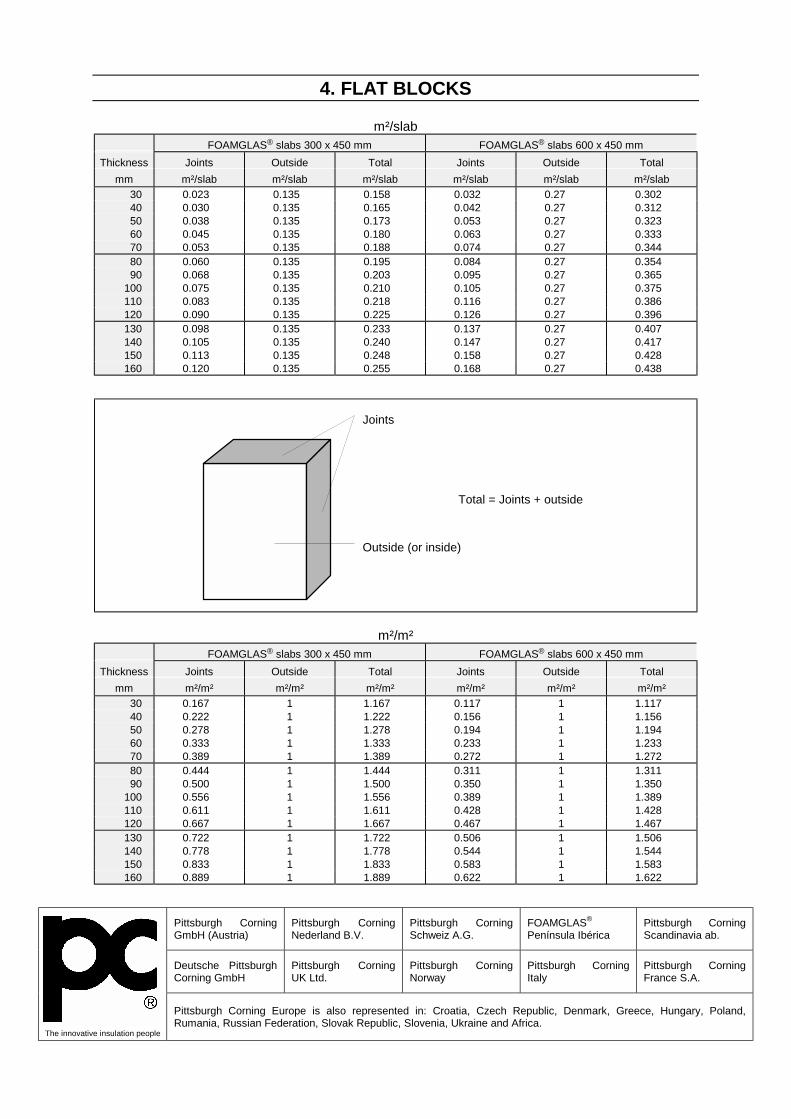
4. FLAT BLOCKS
m²/slab FOAMGLAS® slabs 300 x 450 mm FOAMGLAS® slabs 600 x 450 mm
Thickness Joints Outside Total Joints Outside Total mm m²/slab m²/slab m²/slab m²/slab m²/slab m²/slab
30 0.023 0.135 0.158 0.032 0.27 0.302 40 0.030 0.135 0.165 0.042 0.27 0.312 50 0.038 0.135 0.173 0.053 0.27 0.323 60 0.045 0.135 0.180 0.063 0.27 0.333 70 0.053 0.135 0.188 0.074 0.27 0.344 80 0.060 0.135 0.195 0.084 0.27 0.354 90 0.068 0.135 0.203 0.095 0.27 0.365
100 0.075 0.135 0.210 0.105 0.27 0.375 110 0.083 0.135 0.218 0.116 0.27 0.386 120 0.090 0.135 0.225 0.126 0.27 0.396 130 0.098 0.135 0.233 0.137 0.27 0.407 140 0.105 0.135 0.240 0.147 0.27 0.417 150 0.113 0.135 0.248 0.158 0.27 0.428 160 0.120 0.135 0.255 0.168 0.27 0.438
Joints
Outside (or inside)
Total = Joints + outside
m²/m² FOAMGLAS® slabs 300 x 450 mm FOAMGLAS® slabs 600 x 450 mm
Thickness Joints Outside Total Joints Outside Total mm m²/m² m²/m² m²/m² m²/m² m²/m² m²/m²
30 0.167 1 1.167 0.117 1 1.117 40 0.222 1 1.222 0.156 1 1.156 50 0.278 1 1.278 0.194 1 1.194 60 0.333 1 1.333 0.233 1 1.233 70 0.389 1 1.389 0.272 1 1.272 80 0.444 1 1.444 0.311 1 1.311 90 0.500 1 1.500 0.350 1 1.350
100 0.556 1 1.556 0.389 1 1.389 110 0.611 1 1.611 0.428 1 1.428 120 0.667 1 1.667 0.467 1 1.467 130 0.722 1 1.722 0.506 1 1.506 140 0.778 1 1.778 0.544 1 1.544 150 0.833 1 1.833 0.583 1 1.583 160 0.889 1 1.889 0.622 1 1.622
Pittsburgh Corning GmbH (Austria)
Pittsburgh Corning Nederland B.V.
Pittsburgh Corning Schweiz A.G.
FOAMGLAS® Península Ibérica
Pittsburgh Corning Scandinavia ab.
Deutsche Pittsburgh Corning GmbH
Pittsburgh Corning UK Ltd.
Pittsburgh Corning Norway
Pittsburgh Corning Italy
Pittsburgh Corning France S.A.
The innovative insulation people
Pittsburgh Corning Europe is also represented in: Croatia, Czech Republic, Denmark, Greece, Hungary, Poland, Rumania, Russian Federation, Slovak Republic, Slovenia, Ukraine and Africa.

i02-08/02 1/8
i02
08/02
1. SERVICE CONDITIONSThis specification applies to the insulation of cold piping and equipment installed in the open air or
under cover with a service temperature between +20°C and -260°C.
2. PRELIMINARY CONDITIONS2.1. FOAMGLAS® slabs and pieces should be transported and stored vertically. Handle the packages with care. FOAMGLAS® insulation packages should be protected from the elements whilst in storage and not allowed to come into direct contact with the ground. 2.2. The surface to be insulated should be clean and free from all traces of grease, rust, dust and any foreign matter. The design engineer should decide whether a coat of anticorrosion paint is necessary, and the type of paint compatible with the service temperature and the adhesive used (if any). If he decides to specify a paint, the following rules should be observed: 2.2.1. The surface, if corroded or other wise unsuitable, should be sandblasted before the possible anticorrosion coat is applied (SS-Sa-2 1/2). 2.2.2. Any surface imperfection should be wire brushed and then coated with a new layer of anticorrosion paint. The surface should be perfectly dry before the insulation is applied.
2.2.3. When adhesive is used, the compatibility between the anticorrosion paint and the adhesive should be verified before the insulation is applied. 2.3. The surface and the materials used should be dry before and during application, and should remain dry until start up. 2.4. The application of FOAMGLAS® insulation on pipes or equipment should be done at ambient temperature (no application when piping or equipment is in service without precautions. Do be determined for each case.). 2.5. The temperature limits of the accessory products should be respected during both storage and application. 2.6. Hydrostatic, radiographic and other tests should be completed before the insulation is applied.
3. DETERMINATION OF INSULATION THICKNESS REQUIRED3.1. Heat transfers should be limited to acceptable values regarding both economic and functional aspects. 3.2. The formation of condensation on the external surface of the insulation should be limited. 3.3. For service temperatures below -50°C the thickness of the different insulation layers should
be chosen according to the temperature range of PITTSEAL® 444N: -50°C to +80°C in order to have the external layer in this temperature range. For temperatures ranging from -165°C to -50°C, please consult Pittsburgh Corning Technical Service
LOW
TEMPERATURE PIPING AND EQUIPMENT

2/8 i02-08/02
3.4. Recommended FOAMGLAS® T4 insulation thicknesses. The following table gives the lowest possible operating temperature to control surface condensation and heat gain when conditions are: Ambient temperature : 25°C Wind speed : 5 km/h Relative humidity : 80% Emittance : 0.3 Maximum heat gain of 30 W/m².
Diameter
FOAMGLAS® insulation thicknesses in mm see Facts & Figures (Data sheets A11 and A12)
inch mm 25 40 50 60 70 80 90 100 110 120 130 140 150 160 170 180 190 200 1/4 13.5 -14 -48 -75 -108 -146 -193 -254 3/8 17.2 -12 -43 -68 -97 -131 -172 -223 1/2 21.3 -10 -38 -61 -88 -119 -156 -200 -257 3/4 26.9 -8 -34 -55 -79 -107 -140 -178 -226 1 33.7 -6 -30 -49 -72 -97 -126 -160 -201 -251 11/4 42.4 -4 -27 -44 -64 -87 -113 -143 -179 -221 11/2 48.3 -3 -25 -42 -61 -82 -107 -135 -168 -206 -254 2 60.3 -2 -22 -38 -55 -75 -97 -122 -151 -184 -224 21/2 76.1 -1 -20 -34 -50 -68 -88 -110 -136 -165 -199 -239 3 88.9 -1 -18 -32 -47 -64 -82 -103 -127 -154 -184 -220 -263 4 114.3 0 -16 -29 -43 -58 -75 -93 -114 -138 -164 -194 -230 -272 6 168.3 1 -14 -25 -37 -50 -65 -81 -99 -118 -139 -163 -191 -222 -259 8 219.1 -12 -23 -34 -46 -60 -74 -90 -107 -126 -147 -171 -197 -227 -262 10 273.0 -11 -21 -32 -44 -56 -70 -84 -100 -117 -136 -157 -180 -206 -236 -271 12 323.9 -11 -20 -31 -42 -54 -67 -80 -95 -111 -129 -148 -169 -193 -220 -250 14 355.6 -10 -20 -30 -41 -53 -65 -78 -93 -108 -125 -144 -164 -187 -212 -240 16 406.4 -10 -19 -29 -40 -51 -63 -76 -90 -105 -121 -138 -157 -178 -202 -228 -258 18 457.2 -10 -19 -29 -39 -50 -62 -74 -87 -102 -117 -134 -152 -172 -194 -218 -246 24 609.6 -9 -18 -27 -37 -47 -58 -70 -82 -95 -109 -124 -141 -158 -178 -199 -222 -248 28 711.2 -9 -18 -27 -36 -46 -57 -68 -80 -93 -106 -120 -136 -153 -171 -190 -212 -236 32 812.8 -9 -17 -26 -35 -45 -56 -67 -78 -90 -103 -117 -132 -148 -165 -184 -204 -227 36 914.4 -9 -17 -26 -35 -45 -55 -66 -77 -89 -101 -115 -129 -145 -161 -179 -199 -220 1000.0 -8 -17 -26 -35 -44 -54 -65 -76 -88 -100 -113 -127 -142 -158 -176 -194 -215 2000.0 -8 -16 -24 -33 -42 -51 -61 -71 -81 -92 -104 -116 -129 -143 -157 -173 -189 3000.0 -8 -16 -24 -32 -41 -50 -59 -69 -79 -90 -101 -112 -125 -137 -151 -165 -181
FLAT -7 -15 -23 -31 -39 -48 -57 -66 -75 -85 -95 -105 -116 -127 -139 -151 -164 For other design conditions please contact Pittsburgh Corning.
4. MATERIALS USED4.1. Insulation material The insulation should be FOAMGLAS® cellular glass (see data sheets A11 to A16) in preformed sections, radiused and bevelled lags or slabs. When ordering the insulation, service temperature should be indicated to allow the choice of suitable adhesive for the fabrication of pipe sections or radiused and bevelled lags. The insulation of standard 90° or 45° - bends (R=1.5 D) may be prefabricated in the factory, as for the straight pipe sections. Non-standard bends, T-pieces, reducers and other equipment should be insulated with pieces cut to size and adapted on site. Flanges and valves should be insulated with pipe shells of larger dimensions adapted on site and eventually adhered with PC® 88 ADHESIVE to the inside of the outer casing. This allows for removal of the insulation and control of flanges and valves.
4.2. Anti-corrosion layer If PC® 88 ADHESIVE is used as an adhesive the anti-corrosion layer should not be based on bitumen, tar, silicone or polyurethane. Zinc chromates or similar coatings are generally compatible. The compatibility should be verified before insulation is applied. 4.3. Anti-abrasive LOW TEMPERATURE ANTI-ABRASIVE should be chosen for temperatures from -180°C to +120°C (see data sheet P20) and PC® HIGH TEMPERATURE ANTI-ABRASIVE for temperatures above 120°C or below -180°C (see data sheet P21). This coating is only to be applied if the piping should be submitted to frequent and significant thermal movements or to strong vibrations. The anti-abrasive coating should be applied onto the inner side of the FOAMGLAS® elements which will be in contact with the metal pipe or equipment. Never apply the anti-abrasive on the pipe itself. Application of

3/8 i02 – 08/02
anti-abrasive coating can be done in the factory by spraying or on site by brushing a thin layer to the inside of the insulation layer. The anti-abrasive should be completely dry before the insulation material is applied. 4.4. Joint sealant To take full benefit of the complete tightness of FOAMGLAS® insulation all joints of the outer layer or the only layer must be sealed with appropriate sealers specially if service temperature in below ambient. Most suitable FOAMGLAS® sealers are butyl based products like PITTSEAL® 444NN. PITTSEAL® 444N is a one-component sealer based on polyisobutylene (see data sheet P41). PITTSEAL® 444N should be applied with caulking cartridge or an extrusion gun in beads to one of the jointing edges. 4.5. Adhesive. Care should be taken in selecting an adhesive for cold temperatures. At temperatures down to -50°C the adhesive should, after curing, remain flexible and absorb mechanical and thermal stresses. Down to -50°C this can be done with PC® 88 ADHESIVE, a two-component adhesive based on bitumen modified with polyurethane (see data sheet P05). The temperature of the metal surface should not be lower than +5°C during application. If rapid adhesion is needed the surface to be insulated should be maintained between +20°C and +35°C. 4.6. Resilient insulating material. Low density glass wool or neoprene foam insulation. 4.7. Insulation fixing straps. The straps should be in AISI type 304 (BSI 304 S16) stainless steel and should measure 12.7 mm wide x 0.5 mm thick. Wire to fix FOAMGLAS® shells or segments should be avoided, due to the wire cutting of the FOAMGLAS® surface. 4.8. Tape. Self-adhesive glass fibre reinforced tape.
4.9. Contraction joint covering. Butyl-rubber sheets of +/- 1.2 mm thick should be used. 4.10. Finishes and jackets. A metal jacket or a flexible mastic coating should be chosen. 4.10.1. Metal jacket as finishing cover. 4.10.1.1. Cell filler for outdoor applications. In high wind areas or when the metal jacketing is expected to be subject to mechanical loads or vibrations, a cell filler is recommended for outdoor applications. The cut surface cells may be filled with PITTCOTE® 300 (see data sheet P30). Coverage as a cell filler is about 1.5 kg/m². 4.10.1.2. The metal jacket should be aluminium, steel or aluminised steel sheets, corrugated, flat or hammered, of suitable thickness. The easiest way to applied the jacket is to band it. Pop rivets or screws may also be used after having held the jacket tightly with temporary bands. A cushion layer of fibrous insulation between FOAMGLAS® insulation and the jacket should be avoided. This top layer will absorb the ambient moisture during humid weather and could result in corroding the metal jacket. 4.10.2. Flexible mastic with fabric reinforcement. 4.10.2.1. PITTCOTE® 404 coating (see data sheet P31) is an acrylic water borne mastic giving excellent results in aggressive atmospheres. It is not a vapour barrier but a weather barrier. A regular control and maintenance of mastic finish is recommended. 4.10.2.2. Reinforcement. The reinforcement should be PC® FABRIC 79P (polyester) (see data sheet P50). This product together with PITTCOTE® 404 offers a very flexible outer finish. PC® FABRIC 79G (glass) (see data sheet P51) should be avoided if important differential thermal movements are expected.
5. INSULATION SYSTEMSService temperature of the pipe or equipment will guide requirements made on the insulation system as well as the insulation thickness. 5.1. Service temperatures below ambient to -50°C. (Fig.1) A one layer system is sufficient for this temperature range. A double layer system should be applied when the recommended insulation thickness should be bigger than the maximum
available thickness (see data sheets A11 to A16 regarding thicknesses). 5.1.1. Piping, elbows and fittings. Shells and segments appropriate to the shape of the surface to be insulated should be applied with staggered joints and the joints filled with PITTSEAL® 444N or other suitable mastic. Care should be taken to ensure that the joints are tightly butted when the mastic is applied. This or another mastic should not be used to fill joints

4/8 i02 – 08/02
that are too wide as a result of poor fitting. After applying the shells or segments to the pipe or equipment they will be held in place by means of 2 steel straps per shell or segment.
a a
b bb 1 LOW TEMPERATURE ANTI-ABRASIVE (if specified - see 4.3.) 2 FOAMGLAS® cellular glass 3 PITTSEAL® 444N sealer 4 Metal fixing strap 5a PITTCOTE® 300 cell filler (if specified - see 4.10.1.1.) 5b PC® FABRIC 79 reinforcement 6a Metal jacket 6b PITTCOTE® 404 Fig.1 Single layer systems for service temperatures below ambient to -50°C.
5.1.2. Vessels. (Fig.2 and Fig.3) Segments appropriate to the shape of the surface to be insulated should be applied with staggered joints. Staggering the segments is not needed for vessel heads or other irregular forms. Segments will be adhered and joints filled with PC® 88 ADHESIVE. Temporary banding is needed to give PC® 88 ADHESIVE time to set. Excess of adhesive running out of the joints should be removed before it sets. Extra steel straps are not needed when using PC® 88 ADHESIVE. 5.2. Service temperatures from -50°C down to -180°C. (Fig.4) A double layer system is generally sufficient for this temperature range. The insulation layers should be chosen in such a way that the interface temperature of the two layers is not lower than -50°C.
5.2.1. Piping, elbows, fittings and vessels. Shells and segments appropriate to the shape of the surface to be insulated should be applied with joints that are staggered regarding each other and to the second layer. The first layer should be dry applied and fixed with tape or steel straps. Depending on the diameter of vessels it could be possible that the first layer has to be fixed with steel straps. The second layer should have its joints filled with PITTSEAL® 444N or other suitable mastic. Care should be taken to ensure that the joints are tightly butted when the mastic or adhesive is applied. This or another mastic should not be used to fill joints that are too wide as a result of poor fitting. The second layer will always be held in place by means of 2 steel straps per shell or segment. The insulation of the bottom heads, manholes and other individual items should also be fixed in place with steel straps. These straps should be attached to support rings welded onto the body of the vessel.
1 2 3 4 5 6 7a a
1 2 3 4 5 6 77b b b 1 LOW TEMPERATURE ANTI-ABRASIVE (if specified - see 4.3.) 2 FOAMGLAS® insulation 3 Tape or metal fixing straps 4 PITTSEAL® 444N sealant in the joints of the outer layer 5 Metal fixing straps 6a PITTCOTE® 300 cell filler (if specified - see 4.10.1.1.) 6b PC® FABRIC 79 reinforcement 7a Metal jacket 7b PITTCOTE® 404 Fig.4 Double layer systems for service temperatures from -50°C down to -180°C

5/8 i02 – 08/02
5.3. Service temperatures below -180°C. At this temperature a three layer system should be used. For small pipe diameters a double layer system could be apply depending of weather or service conditions. Many designers and some national codes impose the liquid oxygen compatibility requirements to all applications at temperatures below -180°C. The risk exists that an explosion occurs when liquid oxygen condenses from the air at this temperature or below it. PC® HIGH TEMPERATURE ANTI-ABRASIVE is an inorganic product and should be
used at these temperatures. It can be used to fabricate the FOAMGLAS® elements and as anti-abrasive layer at least for the inner layer. 5.3.1. Piping, elbows, fittings and vessels. All insulation layer should be applied with staggered joints regarding each other and to the other layers. The first and second layer will be dry applied and fixed with steel straps. The outer insulation layer should have its joints filled with PITTSEAL® 444N or other suitable mastic and fixed with steel straps.
12 3
4 1 Horizontal vessel with domed ends.2 FOAMGLAS® vessel segments adhered
with PC® 88 ADHESIVE.3 PC® 88 ADHESIVE in the joints.4 Manhole insulated with same insulation
thickness as vessel.
Fig.2 Vessel insulation. Single layer system for service temperatures below ambient to -50°C. FOAMGLAS® segments adhered and joints sealed with PC® 88 ADHESIVE.
6. PARTICULAR POINTS6.1. Vertical pipe insulation supports. (Fig.5) Vertical insulation should be supported appropriately, the self-supporting height of the insulation is determined taking into account the mechanical resistance of FOAMGLAS® insulation. Angle iron or metal plates should be welded or fixed onto the vessel or piping to support the insulation. The width of the support should be chosen to maintain half the thickness of the outer insulation layer. Should there be varying thicknesses of insulation on a vessel, a support should be placed at the point where the different thicknesses meet.
6.2. Horizontal pipe supports. (Fig.6 and Fig.7) FOAMGLAS® should not be used for fixed points but only for sliding supports that take vertical loads. The high compressive strength of FOAMGLAS® cellular glass allows to avoid thermal bridges by not penetrating the insulation layer at pipe supports. 120° curved rigid metal plates should be placed between the support and the insulation. The surface area of these plates and the distance between supports should be designed to limit the compressive stress on the FOAMGLAS®. Due to the uncertainty related to the outside contact area, a safety factor of 5 is

6/8 i02 – 08/02
recommended. Shells at the support area should be coated with an anti-abrasive, both internally and externally, to fill the surface cells; this is not
necessary for the external surface if it is to be finished with a mastic coating.
SCHEDULES & DETAILS
R
R = T
Pipe diameter
Insulation thickness
Cradle thickness
Minimum length of cradle
L (mm)
Inch min mm
max. mm
T mm
Maximum span in m 3.0 3.5 4.5 5.5 6.0
1/2 & 3/4 25 60
110
50 100 130
2.0 3.2 4.8
260 260 260
_ _ _
_ _ _
_ _ _
_ _ _
1 to 1 1/2 25 50
100
40 90
140
2.0 3.2 4.8
260 260 260
260 260 260
_ _ _
_ _ _
_ _ _
2 to 3 1/2 25 50 90
140
40 80
130 150
2.0 3.2 4.8 6.4
260 260 260 260
260 260 260 260
260 260 260 260
_ _ _ _
_ _ _ _
4 & 5 25 60
110
50 100 180
3.2 4.8 6.4
260 260 260
260 260 260
260 260 260
300 300 300
_ _ _
6 & 8 40 70
150
60 140 180
4.8 6.4 8.0
260 260 260
300 300 300
400 400 400
400 400 400
510 510 510
10 to 12 40
100 160
90 150 200
6.4 8.0 9.5
300 300 300
400 400 400
510 510 510
610 610 610
610 610 610
14 & 16 40 60
130 190
50 120 180 230
6.4 8.0 9.5
11.0
400 400 400 400
510 510 510 510
610 610 610 610
915 915 915 915
915 915 915 915
18 & 20 40 70
140 200
50 130 190
8.0 9.5
11.0 12.7
510 510 510 510
610 610 610 610
760 760 760 760
915 915 915 915
915 915 915 915
24 40 90
150
80 140 200
9.5 11.0 12.7
610 610 610
760 760 760
915 915 915
1070 1070 1070
1070 1070 1070
30 40 130
120 230
12.7 15.9
760 760
915 915
1070 1070
1220 1220
1370 1370
36 40 170
160 230
15.9 19.0
915 915
1070 1070
1220 1220
1370 1370
1530 1530
Fig. 6 SADDLES : FOAMGLAS® S3 insulation (compressive strength : 0.9 N/mm² ).
6.3. Welded connections Supports, cradles, skirts and legs welded directly onto the equipment should be insulated with the same thickness of insulating material as the equipment itself, to avoid thermal bridges. This insulation should extend over a distance equal to
four times the insulation thickness and should in no case be less than 30 cm. 6.4. Joints and precautions for differential thermal movements. (Fig.8) The location of contraction joints should be determined considering the expected pipe

7/8 i02 – 08/02
movements. In addition to contraction joints for a given length of piping, contraction joints should also be placed at any direction change in the piping. Contraction joints should be installed in the inner and outer insulation layers of horizontal piping and equipment. Vertical lines and equipment having support rings should have a contraction joint immediately below each support ring. Each contraction joint should be filled with resilient insulation material. For multi-layer insulation systems a sliding compound should be applied between the insulation layers. This could
be done with PITTSEAL® 444N if temperature allows it. The contraction joint of the outer insulation layer should be covered with a butyl-rubber sheet (+/-1.2 mm thick). This sheet should be sealed with PITTSEAL® 444N and fixed with steel straps. 6.5. Flashing Appropriate techniques and materials should be used to make the areas around nozzles, manholes and other protrusions watertight; this also applies to junctions of horizontal and vertical surfaces.
Thermal contraction of FOAMGLAS® cellular glass and metals based on 20°C ambient
temperature. Operating temperature
in °C FOAMGLAS® cellular glass
mm/m
Carbon steel
mm/m
Stainless steel
mm/m
Aluminium
mm/m -200 -1.54 -1.94 -2.83 -3.93 -150 -1.21 -1.68 -2.37 -3.38 -100 -0.89 -1.26 -1.76 -2.52
-50 -0.53 -0.77 -1.06 -1.53 0 -0.15 -0.23 -0.32 -0.45
50 +0.24 +0.34 +0.47 +0.65
7. SURFACE PROTECTION7.1. Metal jacket Apply sheets of aluminium, steel or aluminised steel, corrugated, flat or hammered to the external surface of the FOAMGLAS® cellular glass. If appropriate due to climatic or mechanical conditions, the external surface of the FOAMGLAS® insulation may first be coated with a single layer of PITTCOTE® 300 mastic that will be given enough drying time before jacket application.
7.2. Mastic coating. Apply a layer of PITTCOTE® 404 with a brush, trowel, gun or gloves. Embed the reinforcement fabric into the layer while it is still tacky. Make sure that the fabric does not tear or wrinkle. The overlap of fabric at joints should be 10 cm. When the first coat is dry to touch, apply a second layer of PITTCOTE® 404 mastic to completely cover the reinforcement fabric and provide a smooth uniform surface (see data sheet P31 for PITTCOTE® 404 and data sheets P50/P51 for PC® FABRIC 79). Ensure that the mastic is completely dry before applying any compatible paint.
1 2 3 1 Adhere +/- 120° of the circumference with small radius segments using PC® 88 ADHESIVE and give adhesive
time to set. Use tape to keep segments temporary in place.(Type SRS, see data sheet A16) 2 Finish the circumference with small radius segments and PC® 88 ADHESIVE when the adhesive of the 120° part
is completely dry. 3 Fill central part with radiused and bevelled segments (Type SHS, see data sheet A16) Fig.3 Application method for tank head segments (Type SHS and SRS) on horizontal
domed ends.

7
8
1 Pipe 2 FOAMGLAS® pipe shells 3 Vertical pipe support 4 Resilient insulating material (see 4.6) 5 Insulation fixing straps 6 PITTSEAL® 444N 7 Metal jacket 8 Butyl-rubber sheet ceiling outer contraction
joint. Fig.5 Vertical pipe support Single layer system for service
temperatures below ambient to -50°C.
1 Piping 2 LOW TEMPERATURE ANTI-ABRASIVE
3 FOAMGLAS® insulation 4 PC® 88 ADHESIVE or other adhesive
(depends of service temperature) 5 Metal jacket 6 Steel saddle or collar Fig.7 Horizontal pipe supports or hangers
(no fixed points).
8
6
1 FOAMGLAS® cellular glass 2 Resilient insulation material 3 Sliding compound, PITTSEAL® 444N if
temperature allows it. 4 PITTCOTE® 300 cell filler (if specified - see
4.10.1.1) 5 Metal jacket 6 PITTSEAL® 444N 7 Butyl-rubber sheet ceiling outer contraction
joint 8 Metal straps Fig.8 Contraction joint double layer
system
While great care is taken in formulating specifications, we cannot be held responsible for them do to imponderables of each specific jobsite.
Pittsburgh Corning GmbH (Austria)
Pittsburgh Corning Nederland B.V.
Pittsburgh Corning Schweiz A.G.
FOAMGLAS® Península Ibérica
Pittsburgh Corning Scandinavia ab.
Deutsche Pittsburgh Corning GmbH
Pittsburgh Corning UK Ltd.
Pittsburgh Corning Norway
Pittsburgh Corning Italy
Pittsburgh Corning France S.A.
The innovative insulation people
Pittsburgh Corning Europe is also represented in: Croatia, Czech Republic, Denmark, Greece, Hungary, Poland, Rumania, Russian Federation, Slovak Republic, Slovenia, Ukraine and Africa.

1/4 i02-10 – 08/02
i02-10
08/02
1. SERVICE CONDITIONS These specifications give guidelines for the insulation of piping and equipment installed in the open air or under cover with a service
temperature between -200°C and -180°C. The insulation system is adapted to steam out the piping.
2. PRELIMINARY CONDITIONS2.1. FOAMGLAS® slabs and pieces should be transported and stored vertically. Handle the packages with care. FOAMGLAS® insulation packages should be protected from the elements whilst in storage and not allowed to come into direct contact with the ground. 2.2. The surface to be insulated should be clean and free from all traces of grease, rust, dust and any foreign matter. The design engineer should decide whether a coat of anticorrosion paint is necessary, and the type of paint compatible with the service temperature and the adhesive used (if any). If he decides to specify a paint, the following rules should be observed: 2.2.1. The surface, if corroded or otherwise unsuitable, should be sandblasted before the possible anticorrosion coat is applied (SS-Sa-2 1/2) 2.2.2. Any surface imperfection should be wire brushed and then coated with a new layer of
anticorrosion paint. The surface should be perfectly dry before the insulation is applied. 2.2.3. When an adhesive is used, the compatibility between the anticorrosion paint and the adhesive should be verified before applying the insulation. 2.3. The surface and the materials used should be dry before and during application, and should remain dry until start up. 2.4. The application of FOAMGLAS® insulation on pipes or equipment should be done at ambient temperature (no application when piping or equipment is in service). 2.5. The temperature limits of the accessory products should be respected during both storage and application. 2.6. Hydrostatic, radiographic and other tests should be completed before the insulation is applied.
3. DETERMINATION OF INSULATION THICKNESS REQUIRED3.1. Heat transfers should be limited to acceptable values regarding both economic and functional aspects. 3.2. The formation of condensation on the external surface of the insulation should be limited. 3.3. To avoid the hardening of the sealant in the joints, the thickness of the different insulation layers should be chosen according to the temperature range of PITTSEAL® 444N (-50 to +80°C) in order to have the external layer in this temperature range. 3.4. Recommended FOAMGLAS® insulation thickness and number of layers for the following conditions: Ambient temperature 20°C, wind speed 5 km/h, emissivity 0.3 (sheet cover), relative humidity 78%, maximum heat gain on the external surface 30 W/m².
PIPE Thicknesses in mm DN inch mm Inside Layer 2 Layer 3 15 25 40 50 80
1/2 1
1 1/2 2 3
21.3 33.7 48.3 60.3 88.9
50 55 65 70 80
50 50 50 50 60
100 150 200 300 350
4 6 8
12 14
114.3 168.3 219.1 323.9 355.6
80 80 80 90
100
60 70 80 80 75
500 600 750
20 24 30
508.0 609.6 762.8
1500.0 3000.0
70 70 70 70 80
70 70 70 70 80
40 50 60 70 70
LIQUID NITROGEN AND OXYGEN
PIPES

2/4 i02-10 – 08/02
4. MATERIALS USED4.1. Insulation material The insulation should be FOAMGLAS® cellular glass (see data sheets A01 to A17) in preformed sections, radiused and bevelled lags or slabs. When ordering the insulation, service temperature should be indicated to allow the choice of suitable adhesive for the fabrication of pipe sections or radiused and bevelled lags. The insulation of standard 90° or 45° - bends (R=1.5 D) may be prefabricated in the factory, as for the straight pipe sections. Non-standard bends, T-pieces, reducers and other equipment should be insulated with pieces cut to size and adapted on site. Flanges and valves should be insulated with pipe shells of larger dimensions adapted on site. 4.2. Anti-corrosion layer The anti-corrosion layer should be compatible with the service temperature. 4.3. Anti-abrasive Layer PC® HIGH TEMPERATURE ANTI-ABRASIVE (see Data Sheet P21) is an inorganic material for high temperatures up to +350°C and for temperatures < -180°C. 4.4. Joint Sealant PITTSEAL® 444N is a one-component, permanent non-hardening butyl based sealer (see Product Sheet P41). It can be applied from cartridges or by extrusion gun. This sealant has been successfully tested for applications where there is a risk of stress corrosion. It has not been tested for its compatibility with liquid oxygen.
4.5. Adhesive. PC® 88 ADHESIVE is a flexible two-component adhesive based on bitumen and polyurethane (see Data Sheet P05). This adhesive has been successfully tested for applications where there is a risk of stress corrosion. It has not been tested for its compatibility with liquid oxygen. 4.6. Resilient Insulating Material Low density mineral wool. 4.7. Fixing Straps The straps should be annealed stainless steel AISI type 304 (AFNOR Z6CN 18-09) and should measure 12.7 mm wide x 0.5 mm thick. Wire to fix FOAMGLAS® shells or segments should be avoided, due to the wire cutting of the FOAMGLAS® surface. 4.8. Surface Protection Metal jacket of corrugated, flat or hammered stainless steel. A thickness of 0.4 mm is usually foreseen for normal uses. The easiest way to apply the jacket is to band it. Pop rivets or screws may also be used after having held the jacket tightly with temporary bands. A cushion layer of fibrous insulation between FOAMGLAS® insulation and the jacket should be avoided. This top layer will absorb the ambient moisture during humid weather.
5. APPLICATION OF PIPE INSULATIONIf possible, all factors influencing the insulation should already be considered at planning stage: temperature ranges and fluctuations, movements and vibrations of the pipe. When the field conditions allow it, the particular points should be insulated first (elbows, T-junctions, flanges, valves and other equipment). 5.1. Anti-abrasive The inner side of the first FOAMGLAS® insulation layer can be coated with an anti-abrasive applied either in the factory or on site, according to service conditions. This can reduce the abrasion caused by frequent differential movements or vibrations. If the anti-abrasive is applied on site, it has to be completely dry before applying the insulation material. 5.2. Pipe Insulation Straight pipe sections should be insulated with appropriate FOAMGLAS® shells or segments.
5.2.1. The insulation is dry applied on the pipes with staggered joints. Whenever possible, the insulation pieces should be staggered vertically by one half element with respect to each other; for short sections (under 2 m), a radial staggering is more suitable. (Fig.1)
Fig.1

3/4 i02-10 – 08/02
5.2.2. It is suitable to keep the inner layer in place by reinforced self-adhesive tape, as the additional thickness of metal strap clamps makes it difficult for the successive layers to be applied upon each other. 5.2.3. To take full benefit of the complete tightness of FOAMGLAS® insulation, all joints of the outer layer must be sealed with PITTSEAL® 444N. Care should be taken that the pieces fit before applying the sealant. Do not use this or any other sealant to fill joints that are too wide, because this results in the formation of thermal bridges. The temperature ranges specified for the sealant should be taken into account when calculating the insulation thickness. (Fig.2) The outer insulation layer should always be held in place by two fixing straps per standard length (600 mm). The sealant will spread in the joints thanks to an even strap tightening; too high tension will cause the insulation shells to break and will thus damage the insulation system. Any damaged pieces should be replaced or at least fixed with sealant at the breaking point.
Fig.2 PITTSEAL® 444N in the joints of the outer layer
5.2.4. The compressive strength of FOAMGLAS® on vertical pipes allows the insulation to be self-supporting up to a great height. But, in order to avoid excessive thermal movement, supporting ring with contraction joints should be placed at suitable distances on vertical straight lines and near singular points like elbows. 5.3. Elbows, Reducers, T-junctions The insulation elbows type 3D (R=1.5 D) may be prefabricated in the factory. Other elbow types, reducers and T-junctions should be insulated with pipe shells or segments adapted on site. As for the pipe insulation, all external layer joints must be sealed with PITTSEAL® 444N. Fixing straps should also be used to keep these insulating parts in place. Wire should be avoided whenever possible due to the wire cutting of the FOAMGLAS® surface.
The tightening of the fixing straps should be performed evenly and carefully to avoid breaking the insulating shells. 5.4. Flanges, Valves and Other Equipment (Pressure Control Valves, Strainers...) Insulation units made of the required shells, segments and slabs are adapted and assembled on site. 5.4.1. Hollow spaces between equipment and insulation should be filled with insulating materials to prevent "pumping" of the enclosed air, in case of extreme temperature changes. These hollow spaces may be filled with small FOAMGLAS® parts (made of chopped up cuttings). 5.4.2. For Flanges, valves and other equipment; since the overall dimensions of these insulating coverings are bigger and therefore more prone to be damaged, metal jackets adapted to the external diameter of the shells should be used. The insulating parts should be adhered inside the metal box. 5.4.3. As was the case for the previous insulating work, all connection joints of these pieces should be sealed to the pipe insulant with a mastic. 5.4.4. The fixing straps should be placed is the same way as for the pipe and elbow insulation. 5.5. Movement joints Movement joints should be foreseen in the insulation system if the thermal movement of the pipe exceeds 1.5 mm/m. Movement joints should also be placed between fixed elements such as fixed points, elbows, T-pieces, flanges, valves and devices when the thermal movement of the pipe exceeds 1.5 mm/m. NOTA: Distance between contraction/expansion
joints is usually foreseen on the basis of a 15 mm differential movement
5.5.1. Thermal contraction of FOAMGLAS® and stainless steel in mm/m
Average temperature
°C
FOAMGLAS®
cellular glass mm/m
Stainless steel
mm/m
-200 - 1.36 - 2.83 -150 - 1.11 - 2.37 -100 - 0.84 - 1.76 -50 - 0.51 - 1.06 0 - 0.16 - 0.47
Ambient temperature: 20°C
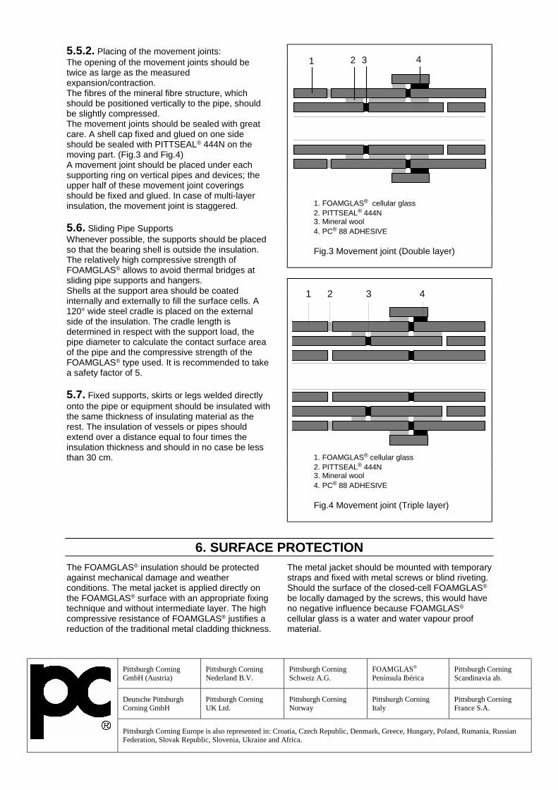
Pittsburgh Corning GmbH (Austria)
Pittsburgh Corning Nederland B.V.
Pittsburgh Corning Schweiz A.G.
FOAMGLAS® Península Ibérica
Pittsburgh Corning Scandinavia ab.
Deutsche Pittsburgh Corning GmbH
Pittsburgh Corning UK Ltd.
Pittsburgh Corning Norway
Pittsburgh Corning Italy
Pittsburgh Corning France S.A.
Pittsburgh Corning Europe is also represented in: Croatia, Czech Republic, Denmark, Greece, Hungary, Poland, Rumania, Russian
Federation, Slovak Republic, Slovenia, Ukraine and Africa.
5.5.2. Placing of the movement joints: The opening of the movement joints should be twice as large as the measured expansion/contraction. The fibres of the mineral fibre structure, which should be positioned vertically to the pipe, should be slightly compressed. The movement joints should be sealed with great care. A shell cap fixed and glued on one side should be sealed with PITTSEAL® 444N on the moving part. (Fig.3 and Fig.4) A movement joint should be placed under each supporting ring on vertical pipes and devices; the upper half of these movement joint coverings should be fixed and glued. In case of multi-layer insulation, the movement joint is staggered. 5.6. Sliding Pipe Supports Whenever possible, the supports should be placed so that the bearing shell is outside the insulation. The relatively high compressive strength of FOAMGLAS® allows to avoid thermal bridges at sliding pipe supports and hangers. Shells at the support area should be coated internally and externally to fill the surface cells. A 120° wide steel cradle is placed on the external side of the insulation. The cradle length is determined in respect with the support load, the pipe diameter to calculate the contact surface area of the pipe and the compressive strength of the FOAMGLAS® type used. It is recommended to take a safety factor of 5. 5.7. Fixed supports, skirts or legs welded directly onto the pipe or equipment should be insulated with the same thickness of insulating material as the rest. The insulation of vessels or pipes should extend over a distance equal to four times the insulation thickness and should in no case be less than 30 cm.
1 2 3 4
1. FOAMGLAS® cellular glass 2. PITTSEAL® 444N 3. Mineral wool 4. PC® 88 ADHESIVE Fig.3 Movement joint (Double layer)
1 2 3 4
1. FOAMGLAS® cellular glass 2. PITTSEAL® 444N 3. Mineral wool 4. PC® 88 ADHESIVE Fig.4 Movement joint (Triple layer)
6. SURFACE PROTECTIONThe FOAMGLAS® insulation should be protected against mechanical damage and weather conditions. The metal jacket is applied directly on the FOAMGLAS® surface with an appropriate fixing technique and without intermediate layer. The high compressive resistance of FOAMGLAS® justifies a reduction of the traditional metal cladding thickness.
The metal jacket should be mounted with temporary straps and fixed with metal screws or blind riveting. Should the surface of the closed-cell FOAMGLAS® be locally damaged by the screws, this would have no negative influence because FOAMGLAS® cellular glass is a water and water vapour proof material.

FOAMGLAS® INSULATION SPECIFICATION
APPLICATION OF FOAMGLAS® INSULATION ONLNG PIPING AND EQUIPMENT
SPECIFICATION # I-COLD-LNG REVISION 01/12/2010 Page 1 of 7
Pittsburgh Corning Pittsburgh Corning Europe S.A./ N.V.800 Presque Isle Drive Pittsburgh, PA 15239-2799 USA (EMEA Headquarters)Toll Free: 800-545-5001 Phone: (724)327-6100 Fax: (724)387-3806 Albertkade 1 Tessenderlo Belgiumhttp://www.foamglas.com/ Phone: +32-13-66-17-21 Fax: +432-13-66-78-54
1. GENERAL NOTES
1.1. This specification covers theapplication of FOAMGLAS® insulation onliquid natural gas piping and equipment(LNG), operating at or near –160°C (-260°F)for control of heat gain. This specificationmay be applicable for indoor or outdoorinstallations.
1.2. This specification is subject to revisionwithout notice. Contact PittsburghCorning for current revision data beforeusing. This specification is offered as aguide for the purpose described herein andshould be employed at the discretion of theuser. No warranty of procedures, either
expressed or implied, is intended. Thefinal application procedure is theresponsibility of the project designerand/or owner.
1.3. The product data sheets referenced inthe text are listed at the end of thespecification. Product data sheets forPittsburgh Corning products may beaccessed on line at:http://www.foamglas.com/industry/en//
1.4. English unit conversions have beenrounded to nearest SI unit equivalent
2. PRELIMINARY CONDITIONS
2.1. FOAMGLAS® pipe insulation andfabricated fittings should be transportedand stored vertically. Handle the packageswith care. FOAMGLAS® insulationpackages should be protected from theelements while in storage and should notbe allowed to come into direct contact withthe ground.
2.2. The surface to be insulated should beclean and free from all traces of grease,rust, dust and any foreign matter. Thedesign engineer should decide whether acoat of anticorrosion paint is necessary,and the type of paint compatible with theservice temperature and the adhesive used(if any). If he decides to specify a paint, thefollowing rules should be observed:
2.2.1. The specifying engineer or ownershall at their option designate a rustinhibitor or corrosion resistant paint to beapplied before the application of anyinsulation. The application of such paintor coating is not a requirement of thisspecification.
2.2.2. Any surface imperfection should bewire brushed and then coated with a newlayer ofanticorrosion paint. The surface should beperfectly dry before the insulation isapplied.
2.2.3. When an adhesive is used, thecompatibility between the anticorrosionpaint and the adhesive should be verifiedbefore applying the insulation.

i02-20 LNG PIPING AND EQUIPMENT REV 01/10/2010 Page 2 of 7
Pittsburgh Corning Pittsburgh Corning Europe S.A./ N.V.800 Presque Isle Drive Pittsburgh, PA 15239-2799 USA (EMEA Headquarters)Toll Free: 800-545-5001 Phone: (724)327-6100 Fax: (724)387-3806 Albertkade 1 B-3980 Tessenderlo Belgiumhttp://www.foamglas.com/ Phone: +32-13-66-17-21 Fax: +32-13-66-78-54
2.3. The surface and the materials usedshould be dry before and duringapplication, and should remain dry untilstart up.
2.4. The application of FOAMGLAS®insulation on pipes or equipment shouldbe done at ambient temperature (noapplication when piping or equipment is inservice).
2.5. The temperature limits of the accessoryproducts should be respected during bothstorage and application.
2.6. Hydrostatic, radiographic and othertests should be completed before theinsulation is applied.
3. DETERMINATION OF REQUIRED INSULATION THICKNESS
3.1. The heat transfers should be limited toacceptable values with respect to botheconomic and functional aspects. Designthickness criteria will limit heat gain tobetween 25 to 37 W/m2 (8 to 12 Btu/hr ft2).In some cases this may also limitcondensation (recommendable). The
insulation thickness shall be determinedthrough calculations based on particularand unique environmental and operatingconditions .Thickness calculations are available fromPittsburgh Corning.
4. MATERIALS USED
4.1. Insulation materialInsulation shall be FOAMGLAS® cellularglass insulation manufactured inaccordance with ASTM C552, “StandardSpecification for Cellular Glass ThermalInsulation”, by Pittsburgh Corning whosequality system for manufacturing,inspecting, and testing of FOAMGLAS®insulation is certified to meet therequirements of ISO 9001:2008.FOAMGLAS® pipe insulation shall be
fabricated according to the requirements ofASTM C1639 “Standard Specification forFabrication of Cellular Glass Pipe andTubing Insulation”.
4.2. Anti-abrasiveThis coating is only to be applied if thepiping should be submitted to frequent andsignificant thermal movements or to strong
vibrations. The anti-abrasive coatingshould be applied onto the inner side of theFOAMGLAS® elements which will be incontact with the metal pipe or equipment.4.2.1 PC® LTAA4.2.2 . Hydrocal® B-11 gypsum cement (seeData Sheet FI-169) or,4.2.3 PC 136 adhesive, used for stainlesssteel piping (see Data Sheet FI-252)
4.3. Joint sealantPITTSEAL® 444N sealant, a one-component, permanent non-hardeningbutyl based sealant or equivalent.
4.4.Contraction joint filler/cushioningblankets if necessary, shall beTEMP-MAT® as supplied by AlphaAssociates 2 Amboy Avenue Woodbridge,NJ 07095 Telephone: (732)634-5700 Fax:

i02-20 LNG PIPING AND EQUIPMENT REV 01/10/2010 Page 3 of 7
Pittsburgh Corning Pittsburgh Corning Europe S.A./ N.V.800 Presque Isle Drive Pittsburgh, PA 15239-2799 USA (EMEA Headquarters)Toll Free: 800-545-5001 Phone: (724)327-6100 Fax: (724)387-3806 Albertkade 1 B-3980 Tessenderlo Belgiumhttp://www.foamglas.com/ Phone: +32-13-66-17-21 Fax: +32-13-66-78-54
(732)634-1430 http://www.alphainc.com/site/ orequal, or Type E needled glass fiber feltthermal insulation containing no organicbinders, manufactured in accordance withASTM C1086. or light density (48 kg/m3 or3 lb/ft3) fibreglass
4.5. Metal Bands shall be
AISI type 304 (BSI 304 S16) stainless steel,13 mm wide x 0.4 mm thick (0.5 in. x 0.016in.), with matching seals.OrAluminum bands with matching seals, 13 x0.5 mm (0.5 in. x 0.020 in.) for piping andequipment with O.D. up to 1219mm (48in.), 19 x 0.5 mm (0.75 in. x 0.020 in.) forlarger O.D.
4.6 Tape shall be Scotch No. 898 tape, ahigh tensile strength, fiber reinforced tapeavailable from 3M Corporation, orequivalent
4.7. Contraction Joint vapour barrierContraction Joint Barrier Sheet shall beminimum 1.6 mm (0.062 in.) thick solidneoprene or butyl rubber as supplied by AAAAcme Rubber Company 2003 E. Fifth St., Bldg#1 Tempe, AZ 85281 Telephone: (480)966-9311Fax: (480)966-2273http://www.acmerubber.com/neosheet.htm or approved equal.
4.8 Reinforcing Mesh Fabric for theweather barrier coating shall be syntheticfabric, 6.5 x 6 mesh, PC® Fabric 79 assupplied by Pittsburgh Corning .Or approved equal
4.9. Protective Coatings or Membranes andFinishesA vapour retarder has to be installed. Thismaterial will fill the cells, improvesmechanical resistance of the system, and isan additional barrier to vapour and liquids.4.9.1 Vapour Retarder Mastic –PITTCOTE® 300 coating, an asphalt mastic,as supplied by Pittsburgh Corning.PITTCOTE® 300 coating must be coveredwith metal jacket.4.9.2 TEROSTAT PCFR monomer coating,as supplied by PC.4.9.3 Hypalon® based coating (typeMonolar® or similar), to be reinforced withsynthetic fabric, as PC® Fabric 79 orsimilar.4.9.4. Alu-butyl sheet4.9.5 Metal JacketUse minimum 0.4 mm (0.016 in.) metaljacket for insulation. Use minimum 0.4 mm(0.016 in.) smooth stainless steel jacket forcaustic service or where the FOAMGLAS®insulation is being used for fire protectionapplications.
5. APPLICATION OF PIPE INSULATION
5.1. Before application of the insulation:5.1.1. apply vapour stop system tocryogenic supports (when required)5.1.2. mark location of insulationterminations (at flanges, , valves, … ) andcontraction/expansion joint location (whenrequired) on the object,5.2. Application of insulation
5.2.1 It is necessary to install the insulationin multiple layers. Two layers willnormally suffice, when respective thicknessare commercially available.5.2.2. The insulation of straight piping,bends, T-pieces, equipment heads,…, willbe fully fabricated to fit; number of pieces

i02-20 LNG PIPING AND EQUIPMENT REV 01/10/2010 Page 4 of 7
Pittsburgh Corning Pittsburgh Corning Europe S.A./ N.V.800 Presque Isle Drive Pittsburgh, PA 15239-2799 USA (EMEA Headquarters)Toll Free: 800-545-5001 Phone: (724)327-6100 Fax: (724)387-3806 Albertkade 1 B-3980 Tessenderlo Belgiumhttp://www.foamglas.com/ Phone: +32-13-66-17-21 Fax: +32-13-66-78-54
as few as possible, and defined bytransport conditions5.2.3 it is strongly recommended to startapplication with fittings; straight pipes tobe cut on site to fit between fittings/marks5.2.4 The first layer of FOAMGLAS®insulation shall be installed dry (using nojoint sealant). The first layer shall besecured with fiber reinforced tape appliedon 300 mm (12 in.) centers, with a 50%overlap of the tape per wrap, or with metalbands5.2.5 Intermediate layers ofFOAMGLAS® insulation shall be appliedwith all joints staggered from those of thepreceding layer. Securement of each layershall be with fiber reinforced tape usingtwo (2) wraps per section or with metalbands5.2.6 The final layer of insulation shall beapplied with all joints staggered from thoseof the preceding layer and sealed with jointsealer. A continuous seal must be providedfor the full length of all joints; care is to betaken sealant in longitudinal andcircumferential joints meet, in order toavoid gaps. poor fitting. It is recommendedto apply the sealant by extrusion (gun orcartridges).5.2.7 The outer layer of FOAMGLAS®insulation shall be secured with 13 wide x0.4 mm thick (1/2 in. x .015 in.) stainlesssteel bands at the rate of two (2) bands,equally spaced, per section of insulation.Bands are to be well secured, closingtightly the longitudinal joints5.2.8 Care must be taken that the outerlayer of FOAMGLAS® insulation is notcracked when secured with the stainlesssteel bands. Cracked or brokenFOAMGLAS® insulation shall be replaced.
5.3 EXPANSION/CONTRACTION JOINTS
Physical contraction of the object, whencooled down to cryogenic temperaturesmay affect insulation system, as differencesin temperature and expansion coefficientwill result in the creation of gaps in theinsulation and finishing, or undue stress,causing cracks.
FOAMGLAS® insulation is thermallystable, having an expansion coefficientlower than and closer to steel than otherinsulation materials. This creates thesituation that when an object is cooled,joints in the insulation will have a tendencyto close; no gaps will be created.
Providing that during application someconsiderations are followed, and a fullyflexible vapour retarder is used, thesolution described in 5.3.1 is moreadequate than a classic exp/contr jointdescribed in 5.3.2, as contraction jointsremain a weak point in the system (fibrous, application, closing of the vapourbarrier foil, …)
5.3.1 NO EXPANSION/CONTRACTIONJOINTSThis system will only function usingvapour barriers that are appropriate forthis system:- Terostat ( as extremely flexible)- Alu/butyl foil, providing anappropriate tape is used on the joints
Every circumferential joint will allowmovement.
- insulation of the inner layers will beapplied so as to leave a circumferentialjoint width of 1mm (0.04 in.) (no sealant)- circumferential joints in the outer layerwill be 3 to 5 mm wide (0.12 in. to 0.20 in.);sealant is applied in beads of sufficient

i02-20 LNG PIPING AND EQUIPMENT REV 01/10/2010 Page 5 of 7
Pittsburgh Corning Pittsburgh Corning Europe S.A./ N.V.800 Presque Isle Drive Pittsburgh, PA 15239-2799 USA (EMEA Headquarters)Toll Free: 800-545-5001 Phone: (724)327-6100 Fax: (724)387-3806 Albertkade 1 B-3980 Tessenderlo Belgiumhttp://www.foamglas.com/ Phone: +32-13-66-17-21 Fax: +32-13-66-78-54
thickness to close the joint at installation; itis recommended to apply two beads in thecircumferential joint (note that completefilling of joint will result in too muchmaterial when closed at service)
It is a good practice to use a wedge atapplication, in order to ensure joint width.
This system is NOT applicable on verticalpiping, as insulation weight will closejoints .
5.3.2 EXPANSION/CONTRACTIONJOINTSThe physical contraction/expansion of thepiping and equipment shall be determinedby the design engineer so thatcontraction/expansion joints in theinsulation can be positioned or located toeliminate any undue stress on theinsulation.Application is recommended between twofixed points ( supports, insulationterminations at valve and flange locations,fittings ), maximum spacing to be 6 m (20ft), providing maximum contraction of25mm (1 in.) can be met.
Contraction joint to be applied in all layers,minimum 150 mm (6 in.) offset, width to be50mm (2 in.) , and filled with resilient lowdensity glass fibre ( fibre directionperpendicular on the pipe )The rubber vapour barrier sheet is wrappedaround the joint, completely sealed withjoint sealer, and banded with stainless steelbands.
On vertical piping, expansion/contractionjoints will be installed at- Under insulation support ring- under pipe support- under top elbow
5.4. valve and flange insulationValves and flanges to be insulatedapplying the same thickness and layeringas the adjacent piping.The adjacent straight piping is provided astep-type juncture in order to allowinsulation to be installed with staggeredjoints.Vapour stop mastic (if required) is appliedto juncture in time to allow completedrying before box installation.
It is recommended to insulate valves andflanges with prefabricated boxes (fittingcovers) made to fit.All voids (if applicable) between object andboxes to be filled with loose wool.
5.5 MISCELLANEOUS5.5.1 Vertical insulation should besupported in an appropriate manner; theself-supporting height of the insulation isdetermined by taking the mechanicalresistance of FOAMGLAS® insulation intoaccount, as well as the movement duringcontraction. For the purpose of dead loadin a vertical support, the insulation willsupport its own weight on the face of thebutt end of the insulation segment for adistance of 15 m (50 ft). The thermalcontraction requirements of the pipe metalwith respect to the insulation system,however, would ultimately govern thenumber of supports and their location.Angle iron or metal plates should bewelded onto the vessel or piping tosupport the insulation. The width of thesupport should be chosen so as to supportthe inner layer(s).To prevent a thermalbreak, the outer layer of insulation shouldbe applied with the mid-point of theinsulation section covering the insulationsupport ring.

i02-20 LNG PIPING AND EQUIPMENT REV 01/10/2010 Page 6 of 7
Pittsburgh Corning Pittsburgh Corning Europe S.A./ N.V.800 Presque Isle Drive Pittsburgh, PA 15239-2799 USA (EMEA Headquarters)Toll Free: 800-545-5001 Phone: (724)327-6100 Fax: (724)387-3806 Albertkade 1 B-3980 Tessenderlo Belgiumhttp://www.foamglas.com/ Phone: +32-13-66-17-21 Fax: +32-13-66-78-54
Should the ring be wider, a supplementarylayer may have to be installed at theinsulation support location. Should therebe varying thicknesses of insulation on a vessel, a support should be placed atthe point where the different thicknessesmeet.5.5.2. Supports, cradles, skirts and legswelded directly onto the equipment shouldbe insulated with the same thickness ofinsulating material as the equipment itself,in order to avoid thermal bridges. Thisinsulation should extend over a distanceequal to four times the insulation thicknessand should never be less than 30 cm (12
in.). The cradle shall be designed toprovide a sufficient bearing area to limitthe compressive force on the insulation to1.4 kg/cm2 (20 psi) maximum at any point.5.5.3 The insulation of the bottom heads,manholes and other individual itemsshould also be fixed in place with stainlesssteel straps.5.5.4 Hollow spaces between object andinsulation should be filled with insulatingmaterials to prevent "pumping" of enclosedair, in case of extreme temperature changes.Hollow spaces may be filled with smallFOAMGLAS® parts (made of chopped upcuttings).
6. INSULATION FINISH
6.1. Mastic & metal finish6.1.1 Over the completed insulationinstallation apply a coat of vapour retardermastic as specified in 4.9.1., at the rate of0.8 to 1.2 liter/m2 (2 - 3 gal./100 ft2).6.1.2 Metal jacketing shall be applied overthe mastic coating with the jointspositioned to shed water. Follow standardpractice of engineers specifications forjacket application.6.1.3 As it may be impossible to avoidmoisture under the cladding due to waterpenetration or condensation, care needs tobe taken to evacuate this as efficiently aspossible (no wicking space materials, drainholes, …)6.2 TEROSTAT coatingTEROSTAT-PCFR is a sprayable andgunable one component polymer.It will be factory applied on all outer layerFOAMGLAS® elements; jointing of theseelements or treatment of minor surfacescan be done on site, using adequatetooling. For this purpose, TEROSTAT-PCFR shall be delivered in suitablecontainers and cartridges.
Apply a bead of TEROSTAT-PCFR on topof all joints, by cartridge, trowel, or gun.The TEROSTAT-PCFR bead will besmoothed flush with the factory appliedTEROSTAT-PCFR surface, on such waythat the coverage will be at least as thick asthe pre-applied coat, and that there will bea complete closure of the coating system.Use an adequate tool like a flexible spatula(Teflon), covered with a soapy watersolution, in order to achieve a smoothfinish with no drag marks.Due to its elasticity, this coating is suited tobe installed on systems requiring noEXPANSION/CONTRACTION joints.
6.3 Alu/butyl foil6.3.1 When applied at site, wrap this sheetover the insulation, avoiding wrinkles andholidays. It is good practice to work withsheets on straight piping, and tapes or cut-to-fit sheets on the fittings. Sufficientpressure should be given at theoverlapping seams, to create a firm bondbetween foils at the butyl material level.

i02-20 LNG PIPING AND EQUIPMENT REV 01/10/2010 Page 7 of 7
Pittsburgh Corning Pittsburgh Corning Europe S.A./ N.V.800 Presque Isle Drive Pittsburgh, PA 15239-2799 USA (EMEA Headquarters)Toll Free: 800-545-5001 Phone: (724)327-6100 Fax: (724)387-3806 Albertkade 1 B-3980 Tessenderlo Belgiumhttp://www.foamglas.com/ Phone: +32-13-66-17-21 Fax: +32-13-66-78-54
It is recommended to heat the material atcolder application temperatures.6.3.2 When the material is pre-applied onthe outer insulation layer, it has a perfectfit with inner layer insulation.Sealing on site is done by covering thejoints by means of Alu/butyl tape,recommended width to be 4” (100mm).Sufficient pressure will ensure sufficientbond between pre-applied foil and tape atbutyl level.
This pre-applied foil application is suitedto be installed on systems, requiring noExpansion/Contraction joints, providing a
specific tape is used over thecircumferential joints ( tape with a non-adhering section in the middle, allowingjoint movements)
6.4. Metal jacketing (optional)Metal jacketing applied as per goodpractice.Reference can be made to existing manuals( CINI, PIP, …)As it may be impossible to avoid moisturein the cladding due to condensation, careneeds to be taken to evacuate this asefficient as possible ( drain holes, nowicking spacer materials, …)
7. INSPECTION/QUALITY ASSURANCE
The general contractor, insulationcontractor and owner shall providesufficient inspection during the insulationand finish application. Continuousinspection of the application is not to beconsidered a requirement of PittsburghCorning.Inspect all insulation and accessorymaterials to be certain they are applied inconformance with the specification
recommendations. Joints should be tight,sealing and flashing should be thoroughand water-tight, and finishes should beuniform and free of defects.
QUALITY ASSURANCEThe insulation manufacturer’s qualitysystem including its implementation, shallmeet the requirements of ISO 9001:2008.
8. CERTIFICATES
The manufacturer will furnish evidence of compliance with the quality system requirementsof ISO 9001:2008
Product Data Sheets
1. PITTSEAL® 444N Sealant: FI-164 4. Hydrocal® B-11 Powder: FI-1692. PITTCOTE® 300: FI-120. 5. PC® Fabric 79: FI-1593. TEROSTAT-PCFR: FI-260
This specification has been prepared by Pittsburgh Corning using generally accepted and appropriate technical information, but it is not intended to be solely relied upon for specific design ortechnical applications. Having no control over the elements of design, installation, workmanship or site conditions, Pittsburgh Corning assumes that persons trained and qualified in theappropriate disciplines will make the actual design choices and installation. Therefore, Pittsburgh Corning disclaims all liability potentially arising from the use or misuse of this specification

FOAMGLAS® INSULATION SPECIFICATION
APPLICATION OF FOAMGLAS® INSULATION ONETHYLENE PIPING AND EQUIPMENT
SPECIFICATION # I-Cold-Ethylene REVISION 01/012/2010 Page 1 of 8
Pittsburgh Corning Corporation Pittsburgh Corning Europe S.A./ N.V.800 Presque Isle Drive Pittsburgh, PA 15239-2799 USA (EMEA Headquarters)Toll Free: 800-545-5001 Phone: (724)327-6100 Fax: (724)387-3806 Albertkade 1 Tessenderlo Belgiumhttp://www.foamglas.com/ Phone: +32-13-611-415 Fax: +32-13-351-567
1. GENERAL NOTES
1.1 This specification covers theapplication of FOAMGLAS® insulation onliquid ethylene piping and equipment,operating at or near –100°C (-150°F) forcontrol of heat gain. This specificationmay be applicable for indoor or outdoorinstallations.1.2. This specification is subject to revisionwithout notice. Contact PittsburghCorning for current revision data beforeusing. This specification is offered as aguide for the purpose described herein andshould be employed at the discretion of theuser. No warranty of procedures, eitherexpressed or implied, is intended. The
final application procedure is theresponsibility of the project designerand/or owner.
1.3. The product data sheets referenced inthe text are listed at the end of thespecification. Product data sheets forPittsburgh Corning products may beaccessed on line at:http://www.foamglas.com/industry/en//
1.4. English unit conversions have beenrounded to nearest SI unit equivalent
2. PRELIMINARY CONDITIONS
2.1. FOAMGLAS® pipe insulation andfabricated fittings should be transportedand stored vertically. Handle the packageswith care. FOAMGLAS® insulationpackages should be protected from theelements while in storage and should notbe allowed to come into direct contact withthe ground.
2.2. The surface to be insulated should beclean and free from all traces of grease,rust, dust and any foreign matter. Thedesign engineer should decide whether acoat of anticorrosion paint is necessary,and the type of paint compatible with theservice temperature and the adhesive used(if any). If he decides to specify a paint, thefollowing rules should be observed:
2.2.1. The specifying engineer or ownershall at their option designate a rustinhibitor or corrosion resistant paint to beapplied before the application of anyinsulation. The application of such paintor coating is not a requirement of thisspecification.2.2.2. Any surface imperfection should bewire brushed and then coated with a newlayer ofanticorrosion paint. The surface should beperfectly dry before the insulation isapplied.2.2.3. When an adhesive is used, thecompatibility between the anticorrosionpaint and the adhesive should be verifiedbefore applying the insulation.

i02-25 ETHYLENE PIPING AND EQUIPMENT REV 01/12/2010 Page 2 of 8
Pittsburgh Corning Corporation Pittsburgh Corning Europe S.A./ N.V.800 Presque Isle Drive Pittsburgh, PA 15239-2799 USA (EMEA Headquarters)Toll Free: 800-545-5001 Phone: (724)327-6100 Fax: (724)387-3806 Albertkade 1 Tessenderlo Belgiumhttp://www.foamglas.com/ Phone: +32-13-611-415 Fax: +32-13-351-567
2.3. The surface and the materials usedshould be dry before and duringapplication, and should remain dry untilstart up.
2.4. The application of FOAMGLAS®insulation on pipes or equipment shouldbe done at ambient temperature (noapplication when piping or equipment is inservice).
2.5. The temperature limits of the accessoryproducts should be respected during bothstorage and application.
2.6. Hydrostatic, radiographic and othertests should be completed before theinsulation is applied.
3. DETERMINATION OF REQUIRED INSULATION THICKNESS
3.1. The heat transfers should be limited toacceptable values with respect to botheconomic and functional aspects. Designthickness criteria will limit heat gain tobetween 25 to 37 W/m2 (8 to 12 Btu/hr ft2).In some cases this may also limitcondensation (recommendable). The
insulation thickness shall be determinedthrough calculations based on particularand unique environmental and operatingconditions .Thickness calculations are available fromPittsburgh Corning.
4. MATERIALS USED
4.1. Insulation materialInsulation shall be FOAMGLAS® cellularglass insulation manufactured inaccordance with ASTM C552, “StandardSpecification for Cellular Glass ThermalInsulation”, by Pittsburgh Corning whosequality system for manufacturing,inspecting, and testing of FOAMGLAS®insulation is certified to meet therequirements of ISO 9001:2008.FOAMGLAS® pipe insulation shall be
fabricated according to the requirements ofASTM C1639 “Standard Specification forFabrication of Cellular Glass Pipe andTubing Insulation”.
4.2. Anti-abrasiveThis coating is only to be applied if thepiping should be submitted to frequent andsignificant thermal movements or to strong
vibrations. The anti-abrasive coatingshould be applied onto the inner side of theFOAMGLAS® elements which will be incontact with the metal pipe or equipment.4.2.1 PC® LTAA4.2.2 . Hydrocal® B-11 gypsum cement (seeData Sheet FI-169) or,4.2.3 PC 136 adhesive, used for stainlesssteel piping (see Data Sheet FI-252)
4.3. Joint sealantPITTSEAL® 444N sealant, a one-component, permanent non-hardeningbutyl based sealant or equivalent.
4.4.Contraction joint filler/cushioningblankets if necessary, shall beTEMP-MAT® as supplied by AlphaAssociates 2 Amboy Avenue Woodbridge,NJ 07095 Telephone: (732)634-5700 Fax:

i02-25 ETHYLENE PIPING AND EQUIPMENT REV 01/12/2010 Page 3 of 8
Pittsburgh Corning Corporation Pittsburgh Corning Europe S.A./ N.V.800 Presque Isle Drive Pittsburgh, PA 15239-2799 USA (EMEA Headquarters)Toll Free: 800-545-5001 Phone: (724)327-6100 Fax: (724)387-3806 Albertkade 1 Tessenderlo Belgiumhttp://www.foamglas.com/ Phone: +32-13-611-415 Fax: +32-13-351-567
(732)634-1430 http://www.alphainc.com/site/ orequal, or Type E needled glass fiber feltthermal insulation containing no organicbinders, manufactured in accordance withASTM C1086. or light density (48 kg/m3 or3 lb/ft3) fibreglass
4.5. Metal Bands shall be
AISI type 304 (BSI 304 S16) stainless steel,12.7 mm wide x 0.4 mm thick (0.5 in. x0.016 in.), with matching seals.OrAluminium bands with matching seals, 13x 0.5 mm (0.5 in. x 0.020 in.) for piping andequipment with O.D. up to 1219mm (48in.), 19 x 0.5 mm (0.75 in. x 0.020 in.) forlarger O.D.
4.6 Tape shall be Scotch No. 898 tape, ahigh tensile strength, fiber reinforced tapeavailable from 3M Corporation, orequivalent
4.7. Contraction Joint vapor barrierContraction Joint Vapor Barrier Sheet shallbe minimum 1.6 mm (0.062 in.) thick solidneoprene or butyl rubber as supplied by AAAAcme Rubber Company 2003 E. Fifth St., Bldg#1 Tempe, AZ 85281 Telephone: (480)966-9311Fax: (480)966-2273http://www.acmerubber.com/neosheet.htm orapproved equal.
4.8 Reinforcing Mesh Fabric for theweather barrier coating shall be syntheticfabric, 6.5 x 6 mesh, PC® Fabric 79 as
supplied by Pittsburgh CorningCorporation.Or approved equal
4.9. FinishesA vapor retarder has to be installed. Thismaterial will fill the cells, improvesmechanical resistance of the system, and isan additional barrier to vapor and liquids. As it may be this will not be covered bymetal jacket, it has to be, in such cases,resistant to weather conditions.
Finishes may be:
4.9.1 Vapor Retarder Mastic – PITTCOTE®300 coating, an asphalt mastic, as suppliedby Pittsburgh Corning Corporation.4.9.2 Terostat PCFR monomer coating, assupplied by PC4.9.2 PITTWRAP® CW30 Jacketing – 30 milself-sealing non-metallic sheet for aboveground applications. Metal jacketing mustbe used over PITTWRAP® CW30 for UVprotection4.9.3Hypalon® based coating (type Monolar® orsimilar), to be reinforced with synthetic fabric, asPC® Fabric 79 or similar4.9.4Terostat PCFR monomer coating, assupplied by P4.9.5Alu-butyl sheet,4.9.5. Metal JacketThe metal jacket should be aluminium, steel oraluminised steel sheets, corrugated, flat orhammered, of suitable thickness.For fire protection applications, a minimum0.016” (0,4 mm) smooth stainless steel jacketshould be used.
5. APPLICATION OF PIPE INSULATION
5.1. Before application of the insulation: 5.1.1. apply vapor stop system tocryogenic supports (when required)

i02-25 ETHYLENE PIPING AND EQUIPMENT REV 01/12/2010 Page 4 of 8
Pittsburgh Corning Corporation Pittsburgh Corning Europe S.A./ N.V.800 Presque Isle Drive Pittsburgh, PA 15239-2799 USA (EMEA Headquarters)Toll Free: 800-545-5001 Phone: (724)327-6100 Fax: (724)387-3806 Albertkade 1 Tessenderlo Belgiumhttp://www.foamglas.com/ Phone: +32-13-611-415 Fax: +32-13-351-567
5.1.2. mark location of insulationterminations (at flanges, , valves, … ) andcontraction joint location (when required)on the object,5.2. Application of insulation5.2.1 It is necessary to install theinsulation in multiple layers. Two layerswill normally suffice, when respectivethickness are commercially available.5.2.2. The insulation of straight piping,bends, T-pieces, equipment heads,…, willbe fully fabricated to fit; number of piecesas few as possible, and defined bytransport conditions5.2.3 it is strongly recommended to startapplication with fittings; straight pipes tobe cut on site to fit between fittings/marks5.2.4 The first layer of FOAMGLAS®insulation shall be installed dry (using nojoint sealant). The first layer shall besecured with fiber reinforced tape appliedon 300 mm (12 in.) centers, with a 50%overlap of the tape per wrap, or with metalbands5.2.5 Intermediate layers ofFOAMGLAS® insulation shall be appliedwith all joints staggered from those of thepreceding layer. Securement of each layershall be with fiber reinforced tape usingtwo (2) wraps per section or with metalbands
5.2.6 The final layer of insulation shall beapplied with all joints staggered from thoseof the preceding layer and sealed with jointsealer. A continuous seal must be providedfor the full length of all joints; care is to betaken sealant in longitudinal andcircumferential joints meet, in order toavoid gaps. poor fitting. It is recommendedto apply the sealant by extrusion (gun orcartridges).5.2.7 The outer layer of FOAMGLAS®insulation shall be secured with 13 wide x
0.38 mm thick (1/2 in. x .015 in.) stainlesssteel bands at the rate of two (2) bands,equally spaced, per section of insulation.Bands are to be well secured, closingtightly the longitudinal joints5.2.8 Care must be taken that the outerlayer of FOAMGLAS® insulation is notcracked when secured with the stainlesssteel bands. Cracked or brokenFOAMGLAS® insulation shall be replaced.
5.3 EXPANSION/CONTRACTION JOINTS
Physical contraction of the object, whencooled down to cryogenic temperaturesmay affect insulation system, as differencesin temperature and expansion coefficientwill result in the creation of gaps in theinsulation and finishing, or undue stress,causing cracks.
FOAMGLAS® insulation is thermallystable, having an expansion coefficientlower than and closer to steel than otherinsulation materials. This creates thesituation that when an object is cooled,joints in the insulation will have a tendencyto close; no gaps will be created.
Providing that during application someconsiderations are followed, and a fullyflexible vapor retarder is used, the solutiondescribed in 5.3.1 is more adequate than aclassic exp/contr joint described in 5.3.2, ascontraction joints remain a weak point inthe system ( fibrous, application, closing ofthe vapor barrier foil, …)5.3.1 NO EXPANSION/CONTRACTIONJOINTS
This system will only function using vaporbarriers that are appropriate for thissystem:- Terostat ( as extremely flexible)

i02-25 ETHYLENE PIPING AND EQUIPMENT REV 01/12/2010 Page 5 of 8
Pittsburgh Corning Corporation Pittsburgh Corning Europe S.A./ N.V.800 Presque Isle Drive Pittsburgh, PA 15239-2799 USA (EMEA Headquarters)Toll Free: 800-545-5001 Phone: (724)327-6100 Fax: (724)387-3806 Albertkade 1 Tessenderlo Belgiumhttp://www.foamglas.com/ Phone: +32-13-611-415 Fax: +32-13-351-567
- Alu/butyl foil, providing anappropriate tape is used on the joints
Every circumferential joint will allowmovement.
- insulation of the inner layers will benormally applied (no sealant)- circumferential joints in the outer layerwill be circa 3 mm wide (0.12 in. to 0.20 in.);sealant is applied in beads of sufficientthickness to close the joint at installation; itis recommended to apply two beads in thecircumferential joint (note that completefilling of joint will result in too muchmaterial when closed at service)
It is a good practice to use a wedge atapplication, in order to ensure joint width.
This system is NOT applicable on verticalpiping, as insulation weight will closejoints .5.3.2 EXPANSION/CONTRACTIONJOINTS
The physical contraction/expansion of thepiping and equipment shall be determinedby the design engineer so thatcontraction/expansion joints in theinsulation can be positioned or located toeliminate any undue stress on theinsulation.Application is recommended between twofixed points ( supports, insulationterminations at valve and flange locations,fittings ), maximum spacing to be 10 m (30ft), providing maximum contraction of25mm (1 in.) can be met.
Contraction joint to be applied in all layers,minimum 150 mm (6 in.) offset, width to be50mm (2 in.) , and filled with resilient low
density glass fibre ( fibre directionperpendicular on the pipe )The rubber vapor barrier sheet is wrappedaround the joint, completely sealed withjoint sealer, and banded with stainless steelbands.
On vertical piping, expansion/contractionjoints will be installed at- Under insulation support ring- under pipe support- under top elbow
5.4. valve and flange insulationValves and flanges to be insulatedapplying the same thickness and layeringas the adjacent piping.The adjacent straight piping is provided astep-type juncture in order to allowinsulation to be installed with staggeredjoints.Vapor stop mastic (if required) is appliedto juncture in time to allow completedrying before box installation.
It is recommended to insulate valves andflanges with prefabricated boxes made tofit.All voids between object and boxes to befilled with loose wool.
5.5 MISCELLANEOUS5.5.1 Vertical insulation should besupported in an appropriate manner; theself-supporting height of the insulation isdetermined by taking the mechanicalresistance of FOAMGLAS® insulation intoaccount, as well as the movement duringcontraction. For the purpose of dead loadin a vertical support, the insulation willsupport its own weight on the face of thebutt end of the insulation segment for adistance of 15 m (50 ft). The thermal

i02-25 ETHYLENE PIPING AND EQUIPMENT REV 01/12/2010 Page 6 of 8
Pittsburgh Corning Corporation Pittsburgh Corning Europe S.A./ N.V.800 Presque Isle Drive Pittsburgh, PA 15239-2799 USA (EMEA Headquarters)Toll Free: 800-545-5001 Phone: (724)327-6100 Fax: (724)387-3806 Albertkade 1 Tessenderlo Belgiumhttp://www.foamglas.com/ Phone: +32-13-611-415 Fax: +32-13-351-567
contraction requirements of the pipe metalwith respect to the insulation system,however, would ultimately govern thenumber of supports and their location.Angle iron or metal plates should bewelded onto the vessel or piping tosupport the insulation. The width of thesupport should be chosen so as to supportthe inner layer(s).To prevent a thermalbreak, the outer layer of insulation shouldbe applied with the mid-point of theinsulation section covering the insulationsupport ring.Should the ring be wider, a supplementarylayer may have to be installed at theinsulation support location.Should there be varying thicknesses ofinsulation on a vessel, a support should be placed atthe point where the different thicknessesmeet.5.5.2. Supports, cradles, skirts and legswelded directly onto the equipment should
be insulated with the same thickness ofinsulating material as the equipment itself,in order to avoid thermal bridges. Thisinsulation should extend over a distanceequal to four times the insulation thicknessand should never be less than 30 cm (12in.). The cradle shall be designed toprovide a sufficient bearing area to limitthe compressive force on the insulation to1.4 kg/cm2 (20 psi) maximum at any point.5.5.3 The insulation of the bottom heads,manholes and other individual itemsshould also be fixed in place with stainlesssteel straps.5.5.4 Hollow spaces between object andinsulation should be filled with insulatingmaterials to prevent "pumping" of enclosedair, in case of extreme temperature changes.Hollow spaces may be filled with smallFOAMGLAS® parts (made of chopped upcuttings).
6. INSULATION FINISH
6.1. Mastic finish with fabric reinforcement.(type Hypalon® based)Apply a layer of mastic with a brush, trowel, gunor gloves. Embed the reinforcement fabric intothe layer while it is still tacky. Make sure that thefabric does not tear or wrinkle. The overlap offabric at joints should be 10 cm. Before the firstcoat becomes dry to touch, apply a second layerof mastic to completely cover the reinforcementfabric and provide a smooth uniform surfaceThickness to apply to obtain the required drycoverage: see client specific requirements and/orproduct specifications
Mastics being organic products with normalageing, regular maintenance is required.
6.2 Terostat coating
TEROSTAT-PC is a sprayable and gunableone component polymer.It will be factory applied on all outer layerFOAMGLAS® elements; jointing of theseelements or treatment of minor surfacescan be done on site, using adequatetooling. For this purpose, Terostat-PC shallbe delivered in suitable containers andcartridges.
Apply a bead of TEROSTAT-PC on top ofall joints, by cartridge, trowel, or gun. TheTerostat-PC bead will be smoothed flushwith the factory applied Terostat-PCsurface, on such way that the coverage willbe at least as thick as the pre-applied coat,and that there will be a complete closure ofthe coating system. Use an adequate tool

i02-25 ETHYLENE PIPING AND EQUIPMENT REV 01/12/2010 Page 7 of 8
Pittsburgh Corning Corporation Pittsburgh Corning Europe S.A./ N.V.800 Presque Isle Drive Pittsburgh, PA 15239-2799 USA (EMEA Headquarters)Toll Free: 800-545-5001 Phone: (724)327-6100 Fax: (724)387-3806 Albertkade 1 Tessenderlo Belgiumhttp://www.foamglas.com/ Phone: +32-13-611-415 Fax: +32-13-351-567
like a flexible spatula (Teflon), coveredwith a soapy water solution, in order toachieve a smooth finish with no dragmarks.Due to its elasticity, this coating is suited tobe installed on systems requiring no E/Cjoints
6.3Asphalt Mastic / PITTWRAP® CW30jacketing) Over the straight runs of pipingapply single layer of wrap, sealing lapseams with manual pressure. All fittings andtransition areas should be covered with a coatingof the PITTCOTE® 300 Finish and PC® 79Fabric. Refer to section 6.1 for application rates.When used in applications subject tosunlight, system must be covered with ametal jacket.
6.4 Alu/butyl foil6.4.1When applied at site, wrap this sheetover the insulation, avoiding wrinkles andholidays.It is good practice to work withsheets on straight piping, and tapes or cut-to-fit sheets on the fittings Sufficientpressure should be given at theoverlapping seams, to create a firm bondbetween foils at the butyl material level.
It is recommended to heat the material atcolder application temperatures.6.4.2When the material is pre-applied onthe outer insulation layer, it has a perfectfit with tulationSealing on site is done by covering thejoints by means of alybutyl tape,recommended width to be 4” (100mm).Sufficient pressure will ensure sufficientbond between pre-applied foil and tape atbutyl level.
This pre-applied foil application is suitedto be installed on systems, requiring no E/Cjoints, providing a specific tape is usedover the circumferential joints ( tape with anon-adhering section in the middle,allowing joint movements)
6.5. Metal jacketing (optional)Metal jacketing applied as per goodpractice.Reference can be made to existing manuals( CIN, Pip, …)As it may be impossible to avoid moisturein the cladding due to condensation, careneeds to be taken to evacuate this asefficient as possible ( drain holes, nowicking spacer materials, …)
7. INSPECTION/QUALITY ASSURANCE
The general contractor, insulation contractor andowner shall provide sufficient inspection duringthe insulation and finish application. Continuousinspection of the application is not to beconsidered a requirement of Pittsburgh Corning .Inspect all insulation and accessory materials tobe certain they are applied in conformance withthe specification recommendations. Joints shouldbe tight, sealing and flashing should be thoroughand water-tight, and finishes should be uniformand free of defects.
QUALITY ASSURANCE
The insulation manufacturer’s quality systemincluding its implementation, shall meet therequirements of ISO 9001:2008.
The manufacturer will furnish evidence ofcompliance with the quality system requirementsof ISO 9001:2008.

FOAMGLAS® INSULATION SPECIFICATION
APPLICATION OF FOAMGLAS® INSULATION ONETHYLENE PIPING AND EQUIPMENT
SPECIFICATION # I-Cold-Ethylene REVISION 01/012/2010 Page 1 of 8
Pittsburgh Corning Corporation Pittsburgh Corning Europe S.A./ N.V.800 Presque Isle Drive Pittsburgh, PA 15239-2799 USA (EMEA Headquarters)Toll Free: 800-545-5001 Phone: (724)327-6100 Fax: (724)387-3806 Albertkade 1 Tessenderlo Belgiumhttp://www.foamglas.com/ Phone: +32-13-611-415 Fax: +32-13-351-567
8. CERTIFICATES
The manufacturer will furnish evidence of compliance with the quality system requirements of ISO9001:2008
Product Data Sheets
1. PITTSEAL® 444N Sealant: FI-164 4. TEROSTAT-PC: FI-2602. PITTCOTE® 300 Finish: FI-120 5. PITTWRAP® CW30: FI-2353. PC® Fabric 79: FI-159 6. Hydrocal® B-11 Powder: FI-169
This specification has been prepared by Pittsburgh Corning Corporation using generally accepted and appropriate technical information, but it is not intended to be solely relied upon for specificdesign or technical applications. Having no control over the elements of design, installation, workmanship or site conditions, Pittsburgh Corning assumes that persons trained and qualified in theappropriate disciplines will make the actual design choices and installation. Therefore, Pittsburgh Corning disclaims all liability potentially arising from the use or misuse of this specification

1/7 i02-60 – 09/00
i02-60
09/00
1. SERVICE CONDITIONSThis specification applies to the insulation of cold piping and equipment installed in the open air or
under cover with a service temperature between +20°C and -260°C.
2. PRELIMINARY CONDITIONS2.1. FOAMGLAS®® slabs and pieces should be transported and stored vertically. Handle the packages with care. FOAMGLAS®® insulation packages should be protected from the elements whilst in storage and not allowed to come into direct contact with the ground. 2.2. The surface to be insulated should be clean and free from all traces of grease, rust, dust and any foreign matter. The design engineer should decide whether a coat of anticorrosion paint is necessary, and the type of paint compatible with the service temperature and the adhesive used (if any). If he decides to specify a paint, the following rules should be observed: 2.2.1. The surface, if corroded or otherwise unsuitable, should be sandblasted before the possible anticorrosion coat is applied (SS-Sa-2 1/2). 2.2.2. Any surface imperfection should be wire brushed and then coated with a new layer of
anticorrosion paint. The surface should be perfectly dry before the insulation is applied. 2.2.3. When adhesive is used, the compatibility between the anticorrosion paint and the adhesive should be verified before the insulation is applied. 2.3. The surface and the materials used should be dry before and during application, and should remain dry until start up. 2.4. The application of FOAMGLAS® insulation on pipes or equipment should be done at ambient temperature (no application without precaution when piping or equipment is in service. To be determined for each case. 2.5. The temperature limits of the accessory products should be respected during both storage and application. 2.6. Hydrostatic, radiographic and other tests should be completed before the insulation is applied.
3. DETERMINATION OF REQUIRED INSULATION THICKNESS The thickness shall be chosen according to the most stringent criteria among the following: 3.1 Heat transfer 3.2 Condensation 3.3 Fire resistance 3.4 Service temperature of sealer and adhesive 3.1. Heat transfers should be limited to acceptable values regarding both economic and functional aspects. 3.2. The formation of condensation on the external surface of the insulation should be limited. 3.3. Several fire resistance tests on steel pipes insulated with FOAMGLAS® cellular glass have been carried out according to prEN
1363-Part 2 - Oct 1996 (hydrocarbon fire). A fire resistance time calculation program has been developed at Ghent University, on the basis of the experimental results. Depending on the needed fire resistance criterion, the Technical Service of Pittsburgh Corning Europe can estimate the required minimum thickness of FOAMGLAS® insulation. The required insulation thickness depends on:
the allowable temperature increase of the steel wall (i.e. 400°C), the diameter of the pipe or vessel, the steel wall thickness, ….
3.4. For service temperatures below -50°C, the thickness of the different FOAMGLAS® T4 insulation layers should be chosen according to the temperature range of PITTSEAL® 444:
HYDROCARBON FIRE RESISTANCE AT LOW TEMPERATURE FOR
PIPING AND EQUIPMENT

2/7 i02-60 – 09/00
-50°C to +80°C in order to have the external layer in this temperature range.
3.5. The recommended FOAMGLAS® T4 insulation thickness to satisfy the hydrocarbon fire resistance requirements has been calculated with the RUG fire resistance computer program based on several tests or comes directly from the tests. Table 1 has been established taking into account an admissible steel pipe temperature of 400°C.
Pipe parameters
Fire resistance of 30 minutes Build-up:
Fire resistance of 60 minutes Build-up:
Fire resistance of 90 minutes Build-up:
Diameter :89 mm Pipe thickness : 5.5 mm
104 mm FOAMGLAS® T4 Stainless steel 0.5 mm
104 mm FOAMGLAS® T4 Pittcote® 300 (optional) 50 mm: Firemaster Stainless steel 0.5 mm CPT
145 mm FOAMGLAS® T4 Pittcote® 300 (optional) 50 mm : Firemaster Stainless steel 0.5 mm CPT
Diameter :168.3 mm Pipe thickness : 5.5 mm
106 mm FOAMGLAS® T4 Stainless steel 0.5 mm
106 mm FOAMGLAS® T4 Pittcote® 300 (optional) 38 mm: Firemaster Stainless steel 0.5 mm CPT
106 mm FOAMGLAS® T4 Pittcote® 300 (optional) 50 mm : Firemaster Stainless steel 0.5 mm CPT
Diameter :273 mm Pipe thickness : 9.3 mm
77 mm FOAMGLAS® T4 Stainless steel 0.5 mm
77 mm FOAMGLAS® T4 Pittcote® 300 (optional) 38 mm: Firemaster Stainless steel 0.5 mm CPT
77 mm FOAMGLAS® T4 Pittcote® 300 (optional) 50 mm : Firemaster Stainless steel 0.5 mm CPT
Diameter :406 mm Pipe thickness : 9.5 mm
70 mm FOAMGLAS® T4 Stainless steel 0.5 mm
70 mm FOAMGLAS® T4 Pittcote® 300 (optional) 25 mm: Firemaster Stainless steel 0.5 mm CPT
70 mm FOAMGLAS® T4 Pittcote® 300 (optional) 38 mm : Firemaster Stainless steel 0.5 mm CPT
Diameter :508 mm Pipe thickness : 9.5 mm
60 mm FOAMGLAS® T4 Stainless steel 0.7 mm
60 mm FOAMGLAS® T4 Pittcote® 300 (optional) 25 mm : Firemaster Stainless steel 0.5 mm CPT
60 mm FOAMGLAS® T4 Pittcote® 300 (optional) 38 mm : Firemaster Stainless steel 0.5 mm CPT
Diameter :813 mm Pipe thickness : 9.5 mm
50 mm FOAMGLAS® T4 Stainless steel 0.7 mm
50 mm FOAMGLAS® T4 Pittcote® 300 (optional) 25 mm : Firemaster Stainless steel 0.5 mm CPT
50 mm FOAMGLAS® T4 Pittcote® 300 (optional) 38 mm : Firemaster Stainless steel 0.5 mm CPT
Table 1 Symbols: Firemaster : Firemaster Blanket X 607TM CPT: ScotchrapTM 52 Corrosion protection tape or equivalent.
4. MATERIALS USED
4.1. Insulation material The insulation should be FOAMGLAS® cellular glass (see data sheets A11 to A17) in preformed shells, radiused and bevelled lags or slabs. When ordering the insulation, service temperature should be indicated to allow the choice of suitable adhesive for the fabrication of pipe shells or radiused and bevelled lags. The insulation of standard 90° or 45° - elbows (R=1.5 D) may be prefabricated in the factory, as for the straight pipe shells. Non-standard elbows, T-pieces, reducers and other equipment should be insulated with pieces cut to size and adapted on site.
Flanges and valves should be insulated with pipe shells of larger dimensions adapted on site and eventually adhered with PC®88 ADHESIVE to the inside of the outer casing. This allows for removal of the insulation and control of flanges and valves. 4.2. Anti corrosion layer If PC® 88 ADHESIVE is used as an adhesive, the anti corrosion layer should not be based on bitumen, tar, silicone or polyurethane. Zinc chromates or similar coatings are generally compatible. The compatibility should be verified before the insulation is applied.

3/7 i02-60 – 09/00
4.3. Anti-abrasive PC® ANTI-ABRASIVE COMPOUND 2A should be chosen for temperatures from -180°C to +120°C (see data sheet P20) and PC® HIGH TEMPERATURE ANTI-ABRASIVE for temperatures above 120°C or below -180°C (see data sheet P21). This coating is only to be applied if the piping should be submitted to frequent and significant thermal movements or to strong vibrations. The anti-abrasive coating should be applied onto the inner side of the FOAMGLAS® elements which will be in contact with the metal pipe or equipment. Never apply the anti-abrasive on the pipe itself. Application of anti-abrasive coating can be done in the factory by spraying or on site by brushing a thin layer to the inside of the insulation layer. The anti-abrasive should be completely dry before the insulation material is applied. 4.4. Joint sealant To take full benefit of the complete tightness of FOAMGLAS® insulation, all joints of the outer layer or of the only layer must be sealed with appropriate sealers, specially if service temperature is below ambient. Most suitable FOAMGLAS® sealers are butyl based products like PITTSEAL® 444. PITTSEAL® 444 is a one-component sealer based on polyisobutylene (see data sheet P41). Temperature range –50°C to +80°C. PITTSEAL® 444 should be applied with a caulking cartridge or extrusion gun in beads to one of the jointing edges. 4.5. Adhesive. Care should be taken in selecting an adhesive for cold temperatures. At temperatures down to -50°C the adhesive should, after curing, remain flexible and absorb mechanical and thermal stresses. Down to -50°C this can be done with PC® 88 ADHESIVE, a two-component adhesive based on bitumen and polyol for component one and isocyanate for component two (see data sheet P05). The temperature of the metal surface should not be lower than +5°C during application. If rapid adhesion is needed the surface to be insulated should be maintained between +20°C and +35°C. 4.6. Firemaster Blanket X 607TM or equivalent. Firemaster Blanket X 607TM is a non-combustible, flexible mat manufactured from alkaline earth silicate fibres suitable
for use in both cellulosic and hydrocarbon fire protection applications. The required quality has a density of 128 kg/m³. 4.7. Resilient insulating material. Low density glass wool. 4.8. Scotchrap
TM 52 Corrosion Protection Tape
The tape is a composite of an all-weather, polyvinyl chloride (PVC) backing and a thick, rubber mastic based, pressure-sensitive adhesive. 4.9. Cell filler PITTCOTE
® 300 is an asbestos-free single
component solvent cutback of a selected bitumen base containing a high percentage of fibres and other mineral fillers blended to give a resilient, resistant, flexible and watertight coating with a very low permeability to water vapour. If specified, the cut outer surface of the outer layer of the FOAMGLAS® T4 insulation cells shall be filled with PITTCOTE® 300 (see data sheet P30). The coverage as a cell filler is about 1.5 kg/m². 4.10. Tape. Self-adhesive glass fibre reinforced tape. 4.11. Insulation fixing straps. The straps should be in AISI type 304 (BSI 304 S16) stainless steel and should measure 12.7 mm wide x 0.5 mm thick or 19 mm wide x 0.75 mm thick depending on the dimensions of the vessels or pipings. Wire to fix FOAMGLAS® shells or segments should be avoided, due to the wire cutting of the FOAMGLAS® surface. 4.12 Metal jacket for covering. The metal jacket should be flat stainless steel of suitable thickness. For pipe diameters ≤ 273 mm, the recommended stainless steel thickness should be equal to minimum 0.5 mm. For pipe diameters > 273 mm, the recommended stainless steel thickness should be equal to minimum 0.7 mm. The easiest way to apply the jacket is to band it, 3 stainless steel straps per meter run. 4.13. Contraction joint covering. Butyl-rubber sheets of +/- 1.2 mm thick should be used.

4/7 i02-60 – 09/00
5. HYDROCARBON FIRE RESISTANCE OF 30 MINUTES 5.1. Service temperatures below ambient to -50°C. (Fig.1) A one-layer FOAMGLAS® T4 insulation system is sufficient for this temperature range. A double layer FOAMGLAS® T4 system should be applied when the recommended insulation thickness is bigger than the maximum available thickness (see data sheets A11 to A17). 5.1.1. Piping, elbows and fittings. Shells and segments appropriate to the shape of the surface to be insulated should be applied
with staggered joints filled with PITTSEAL® 444 or another suitable mastic. Care should be taken to ensure that the joints are tightly butted when the mastic is applied. This or another mastic should not be used to fill joints that are too wide as a result of poor fitting. After applying the shells or segments to the pipe or equipment they will be held in place by means of 2 stainless steel straps per shell or segment. A stainless steel jacketing of suitable thickness is held in place by means of 3 stainless steel straps per meter run.
7
1 PC
® ANTI- ABRASIVE Compound 2A (if specified -see 4.3)
2 FOAMGLAS® Cellular Glass Insulation 3 PITTSEAL
® 444 sealer
4 Stainless steel straps (2 per standard length) 5 PITTCOTE
® 300 as cell filler (if specified – see 4.9)
6 Stainless steel straps (3 per meter run) 7 Stainless steel jacketing Fig.1 Single layer systems for service temperatures below ambient to -50°C.
5.1.2. Vessels. Segments appropriate to the shape of the surface to be insulated should be applied with staggered joints. Staggering the segments is not needed for vessel heads or other irregular forms. Segments will be adhered and joints filled with PC® 88 ADHESIVE. Temporary banding is needed to give PC® 88 ADHESIVE time to set. Excess of adhesive running out of the joints should be removed before it sets. Extra stainless steel straps are not needed when using PC® 88 ADHESIVE.
A stainless steel jacketing of suitable thickness is held in place by means of 3 stainless steel straps per meter run. 5.2. Service temperatures from -50°C down to -180°C. (Fig.2) A double layer system is generally sufficient for this temperature range. The insulation layers should be chosen in such a way that the interface temperature of the two layers is not lower than -50°C.

5/7 i02-60 – 09/00
5.2.1. Piping, elbows, fittings and vessels. Shells and segments appropriate to the shape of the surface to be insulated should be applied with joints that are staggered to each other and to the second layer. The first layer should be dry applied and fixed with tape or stainless steel straps. Depending on the diameter of the vessel, it could be necessary the first layer to fix with stainless steel straps. The second layer should have its joints filled with PITTSEAL® 444 or another suitable mastic. Care should be taken to ensure that the joints are tightly butted when the mastic or adhesive is applied. This or
another mastic should not be used to fill joints that are too wide as a result of poor fitting. The second layer will always be held in place by means of 2 stainless steel straps per shell or segment. The insulation of the bottom heads, manholes and other individual items should also be fixed in place with stainless steel straps. These straps should be attached to support rings welded onto the body of the vessel. A stainless steel jacketing of suitable thickness is held in place by means of 3 stainless steel straps per meter run.
1 2 3 4 5 6 7 8
1 PC
® ANTI- ABRASIVE Compound 2A (if specified -see 4.3)
2 FOAMGLAS®® Cellular Glass Insulation
3 Self adhesive glass reinforced tape or stainless steel straps (2 per standard length) 4 PITTSEAL
® 444 sealant in the joints of the outer layer
5 Stainless steel straps (2 per standard length) 6 PITTCOTE
® 300 as cell filler (if specified - see 4.9)
7 Stainless steel jacketing 8 Stainless steel straps ( 3 per meter run) Fig.2 Double layer systems for fire resistance of 30 minutes and service temperatures from -50°C down to -180°C
5.3. Service temperatures below -180°C. At this temperature a three-layer system should be used. For small pipe diameters a double layer system could be applied depending on weather or service conditions. Many designers and some national codes impose the liquid oxygen compatibility requirements to all applications at temperatures below -180°C. The risk exists that an explosion occurs when liquid oxygen condenses from the air at this temperature or below it. PC® HIGH TEMPERATURE ANTI-ABRASIVE is an inorganic product and should be used at these temperatures. It can be used to fabricate the
FOAMGLAS® elements and as anti-abrasive layer at least for the inner layer. 5.3.1. Piping, elbows, fittings and vessels. All insulation layers should be applied with joints staggered to each other and to the other layers. The first and second layers will be dry applied and fixed with stainless steel straps. The outer insulation layer should have its joints filled with PITTSEAL® 444 or another suitable mastic and fixed with stainless steel straps. A stainless steel jacketing of suitable thickness is held in place by means of 3 stainless steel straps per meter run.

6/7 i02-60 – 09/00
6. HYDROCARBON FIRE RESISTANCE OF 60 AND 90 MINUTES When the fire requirement is particularly high, it can be advisable to recommend a FOAMGLAS® / Firemaster Blanket X 607TM composite system. The FOAMGLAS® insulation should ensure that the thermal requirements are met. 6.1. Service temperatures below ambient to -50°C. (Figure 3 ) Based on thermal requirements, one layer of FOAMGLAS® T4 insulation is generally sufficient for this temperature range. Two layers of FOAMGLAS® T4 insulation should be applied when the recommended insulation thickness is bigger than the maximum available thickness (see data sheets A11 to A17 regarding thicknesses). 6.1.1. Piping, elbows and fittings. Shells and segments appropriate to the shape of the surface to be insulated should be applied with staggered joints and the joints filled with PITTSEAL® 444 or another suitable mastic. Care should be taken to ensure that the joints are tightly butted when the mastic is applied. This or another mastic should not be used to fill joints that are too wide as a result of poor fitting. After applying the shells or segments to the pipe or equipment they will be held in place by means of 2 stainless steel straps per shell or segment. If specified, the cut surface of the FOAMGLAS® T4 insulation cells shall be filled with PITTCOTE® 300. A determined thickness of Firemaster Blanket X 607TM (table 1) is correctly unrolled and fixed on the FOAMGLAS® surface. A stainless steel jacketing of suitable thickness is held in place by means of 3 stainless steel straps per meter run. A good vapour barrier, Scotchrap
TM 52
Corrosion Protection Tape or equivalent, is carefully applied on the stainless steel jacketing to avoid any water or water vapour penetration. 6.1.2. Vessels. Segments appropriate to the shape of the surface to be insulated should be applied with staggered joints. Staggering the segments is not needed for vessel heads or other irregular forms. Segments will be adhered and joints filled with PC® 88 ADHESIVE. Temporary banding is needed to give PC® 88 ADHESIVE time to set. Excess of adhesive running out of the joints should be removed before it sets. Extra stainless steel straps are not needed when using PC® 88 ADHESIVE. If specified, the cut surface of the FOAMGLAS® T4 insulation cells shall be filled with PITTCOTE® 300. A determined thickness of Firemaster Blanket X 607TM or equivalent (table 1) is correctly unrolled and fixed on the FOAMGLAS® surface.
A stainless steel jacketing of suitable thickness is held in place by means of 3 stainless steel straps per meter run. A good vapour barrier, Scotchrap
TM 52
Corrosion Protection Tape or equivalent, is carefully applied on the stainless steel jacketing to avoid any water or water vapour penetration. 6.2. Service temperatures from -50°C down to -180°C. (Figure 3 ) Based on thermal requirements, two layers of FOAMGLAS® T4 insulation are generally sufficient for this temperature range. The FOAMGLAS® T4 insulation layers should be chosen in such a way that the interface temperature of the two layers is not lower than -50°C. 6.2.1. Piping, elbows, fittings and vessels. Shells and segments appropriate to the shape of the surface to be insulated should be applied with joints that are staggered to each other and to the second layer. The first layer should be dry applied and fixed with tape or stainless steel straps. Depending on the diameter of the vessel, it could be necessary to fix the first layer with stainless steel straps. The second layer should have its joints filled with PITTSEAL® 444 or another suitable mastic. Care should be taken to ensure that the joints are tightly butted when the mastic or adhesive is applied. This or another mastic should not be used to fill joints that are too wide as a result of poor fitting. The second layer will always be held in place by means of 2 stainless steel straps per section or segment. The insulation of the bottom heads, manholes and other individual items should also be fixed in place with stainless steel straps. These straps should be attached to support rings welded onto the body of the vessel. If specified, the cut surface of the FOAMGLAS® T4 insulation cells shall be filled with PITTCOTE 300. A determined thickness of Firemaster Blanket X 607TM or equivalent (table 1) is correctly unrolled and fixed on the FOAMGLAS® surface. A stainless steel jacketing of suitable thickness is held in place by means of 3 stainless steel straps per meter run. A good vapour barrier, Scotchrap
TM 52
Corrosion Protection Tape or equivalent, is carefully applied on the stainless steel jacketing to avoid any water or water vapour penetration.

6.3. Service temperatures below -180°C. At this temperature, three layers of FOAMGLAS® T4 insulation should be used. For small pipe diameters a double layer system could be applied depending on weather or service conditions. Many designers and some national codes impose the liquid oxygen compatibility requirements to all applications at temperatures below -180°C. The risk exists that an explosion occurs when liquid oxygen condenses from the air at this temperature or below it. PC® HIGH TEMPERATURE ANTI-ABRASIVE is an inorganic product and should be used at these temperatures. It can be used to fabricate the FOAMGLAS® elements and as anti-abrasive layer at least for the inner layer. 6.3.1. Piping, elbows, fittings and vessels. All insulation layers should be applied with joints staggered to each other and to the other layers. The first and second layers will be dry applied and fixed with stainless steel straps.
The outer insulation layer should have its joints filled with PITTSEAL® 444 or another suitable mastic and fixed with stainless steel straps. If specified, the cut surface of the FOAMGLAS® T4 insulation cells shall be filled with PITTCOTE® 300. A determined thickness of Firemaster Blanket X 607TM or equivalent (table 1) is correctly unrolled and fixed on the FOAMGLAS® surface. A stainless steel jacketing of suitable thickness is held in place by means of 3 stainless steel straps per meter run. A good vapour barrier Scotchrap
TM 52 Corrosion
Protection Tape or equivalent, is carefully applied on the stainless steel jacketing to avoid any water or water vapour penetration.
Pittsburgh Corning GmbH (Austria)
Pittsburgh Corning Nederland B.V.
Pittsburgh Corning Schweiz A.G.
FOAMGLAS® Península Ibérica
Pittsburgh Corning Scandinavia ab.
Deutsche Pittsburgh Corning GmbH
Pittsburgh Corning UK Ltd.
Pittsburgh Corning Norway
Pittsburgh Corning Italy
Pittsburgh Corning France S.A.
The innovative insulation people
Pittsburgh Corning Europe is also represented in: Croatia, Czech Republic, Denmark, Greece, Hungary, Poland, Rumania, Russian Federation, Slovak Republic, Slovenia, Ukraine and Africa.

i02-70 - 02/05 Page 1/3
i02-70 02/05
1. SERVICE CONDITIONS This specification covers the application of cellular glass insulation and accessory materials
to piping and equipment systems operating at below ambient temperatures.
2. PRELIMINARY CONDITIONS2.1. FOAMGLAS® slabs and pieces should be transported and stored vertically. Handle the packages with care. FOAMGLAS® insulation packages should be protected from the elements whilst in storage and not allowed to come into direct contact with the ground. 2.2. The surface to be insulated should be clean and free from all traces of grease, rust, dust and any foreign matter. The design engineer should decide whether a coat of anticorrosion paint is necessary, and the type of paint compatible with the service temperature and the adhesive used (if any). If he decides to specify a paint, the following rules should be observed: 2.2.1. The surface, if corroded or otherwise unsuitable, should be sandblasted before the possible anticorrosion coat is applied (SS-Sa-21/2). 2.2.2. Any surface imperfection should be wire brushed and then coated with a new layer of anticorrosion paint. The surface should be perfectly dry before the insulation is applied. 2.2.3. When an adhesive is used, the compatibility between the anticorrosion paint and
the adhesive should be verified before applying the insulation. 2.3. The surface and the materials used should be dry before and until the end of the application. 2.4. The application of FOAMGLAS® insulation on pipes or equipment should be done at ambient temperature (No application when piping or equipment is in service; special precautions should be taken and determined on a case by case basis). 2.5. The temperature limits of the accessory products should be respected during both storage and application. 2.6. Any deformation of the piping shall be avoided during application. For this purpose, the piping shall be supported at adequate intervals. 2.7. Hydrostatic, radiographic and other tests should be completed before the insulation is applied.
3. DETERMINATION OF THE REQUIRED INSULATION THICKNESS3.1. Heat transfers should be limited to acceptable values regarding both economic and functional aspects. 3.2. The formation of condensation on the external surface of the insulation should be limited.
3.3. For service temperatures below -60°C, the thickness of the different FOAMGLAS® T4 insulation layers should be chosen according to the temperature range of TEROSTAT PC: -60°C to +100°C in order to have the external layer in this temperature range.
4. MATERIALS USEDThe materials listed below are appropriate for this specification.
APPLICATION OF FOAMGLAS® -TEROSTAT INSULATION SYSTEM
FOR BELOW-AMBIENT PIPING AND EQUIPMENT SYSTEMS

i02-70 - 02/05 Page 2/3
4.1. Insulation material The insulation should be FOAMGLAS® cellular glass in preformed sections, radiused and bevelled lags or slabs. The operating temperature must be indicated so that an adequate adhesive can be chosen when fabricating. 4.2. Anti-abrasive PC® LOW-TEMPERATURE ANTI ABRASIVE should be chosen for temperatures from -180°C to +120°C and PC® HIGH-TEMPERATURE ANTI-ABRASIVE for temperatures above 120°C (see data sheet P21). This coating should normally only be applied when the piping is submitted to frequent and significant thermal movements or strong vibrations. The anti-abrasive coating should be applied onto the inner side of the FOAMGLAS® elements which are in contact with the metal pipe or the equipment. Never apply the anti-abrasive on the pipe itself. The anti-abrasive coating can be applied in the factory by spraying or on site by brushing a thin layer on the inside of the insulation layer. The anti-abrasive should be completely dry before applying the insulation material. 4.3. Joint sealant To take full benefit of the complete water-vapour tightness of FOAMGLAS® insulation, all joints of the outer layer or of the only layer must be totally sealed with TEROSTAT PC, especially if service temperature is below ambient.
4.4. Tape Self-adhesive tape, reinforced with glass fabric. Or Aluminium lined butyl rubber self-adhesive tape 4.5. Insulation fixing straps The straps shall be in AISI type 304 (BSI 304 S16) stainless steel and should measure 12 mm wide x 0.4 mm thick or 19 mm wide x 0.5 mm thick depending on the dimensions of the vessels or piping. Wire to fix FOAMGLAS® shells or segments should be avoided, due to the wire cutting of the FOAMGLAS® surface. 4.6. Finishes and Claddings 4.6.1 Vapour retardant mastic Foamglas-Terostat elements will be supplied (Foamglas elements, covered with a factory applied layer of Terostat PC); Terostat PC shall be supplied in suitable containers for on the job finishing. 4.6.2 Metal jacket for covering. A metal-jacket finish is only required in high mechanical-abuse areas. The metal jacket should of suitable thickness. It is recommended to fix the jacket by banding it, 3 stainless steel straps per meter run. . 4.6.3 Contraction joint covering. Butyl-rubber sheets of +/- 1.2 mm thick should be used.
5. APPLICATION5.1. The FOAMGLAS® -Terostat insulation system is not adhered to the piping but firmly butted onto it. The cellular glass shells shall be applied with staggered and carefully butted joints. Each section of inner layer shall be tightly fixed in place with two self-adhesive, glass-fibre reinforced tapes, applied with minimum overlap of 150 mm, or stainless steel straps. All the joints shall be carefully adjusted to avoid any voids which can be eliminated by refitting the shells or by replacing them. Joint width to be 2-3mm.
Single layer applications and outer layer of multiple layer applications will have Terostat PC applied to all longitudinal and circumferential joints. The Terostat PC is applied by cartridge to one of the mating surfaces, to the outmost outer side of the joint to give a bead of 7 mm diameter, at outer layer thicknesses of 50 mm or less; for outer layer thicknesses of 60 mm and above, a second bead will be applied in the inner half of the joint. Foamglas-Terostat system will be firmly tensioned using tensioning band system.
Terostat PC squeezed out of the joint is to be smoothed flush with the factory applied Terostat PC surface ( use adequate tool, like a flexible spatula, covered with soapy water solution; this will enable to achieve a smooth surface without drag marks ). Insulation fixing straps or butyl rubber tape, if required, shall be applied after having smoothed the joints; tensioning straps to be removed. For application at service temperatures below – 100 °C, contact your PC industrial sales manager.

i02-70 - 02/05 Page 3/3
a a
1 PC® LOW TEMPERATURE ANTI-ABRASIVE (if specified - see 4.2.) 2 FOAMGLAS® cellular glass 3 TEROSTAT PC joint sealant 4 Metal fixing strap ( if required ) 5 TEROSTAT PC (factory applied) 6 Metal jacket (if specified) Fig.1 Single layer systems for service temperatures below ambient to -60°C.
1 2 3 4 5 6 7a a
1 PC® ANTI-ABRASIVE (if specified - see 4.3.) 2 FOAMGLAS® insulation 3 Tape or metal fixing straps 4 TEROSTAT PC sealant in the joints of the outer layer 5 Metal fixing straps ( if required ) 6a TEROSTAT PC (factory applied) 7a Metal jacket (if specified) Fig.2 Double layer systems for service temperatures below -60°C
Application of TEROSTAT to joints
Application of shells to pipe
Banding and finishing

i02-90-08/02 1/4
i02-90
08/02
1. SERVICE CONDITIONS. This specification applies to the insulation of chilled water pipes and equipment installed in the
open air or under cover with a service temperature between -4°C and +15°C.
2. PRELIMINARY CONDITIONS. 2.1. FOAMGLAS® slabs and pieces should be transported and stored vertically. Handle the packages with care. FOAMGLAS® insulation packages should be protected from the elements whilst in storage and not allowed to come into direct contact with the ground. 2.2. The surface to be insulated should be clean and free from all traces of grease, rust, dust and any foreign matter. An anticorrosion paint should be applied. The following rules should be applied: 2.2.1. The surface, if corroded or other wise unsuitable, should be sandblasted before the anticorrosion coat is applied (SS-Sa-2 1/2). 2.2.2. Any surface imperfection should be wire brushed and then coated with a new layer of anticorrosion paint. The surface should be perfectly dry before the insulation is applied.
2.2.3. The compatibility between the anticorrosion paint and the adhesive should be verified before the insulation is applied. 2.3. The surface and the materials used should be dry before and during application, and should remain dry until start up. 2.4. The application of FOAMGLAS® insulation on pipes or equipment should be done at ambient temperature (no application when piping or equipment is in service without precautions. Do be determined for each case.). 2.5. The temperature limits of the accessory products should be respected during both storage and application.
3. DETERMINATION OF INSULATION THICKNESS REQUIRED. 3.1. Heat transfers should be limited to acceptable values regarding both economical and functional aspects. 3.2. The formation of condensation on the external surface of the insulation should be limited.
Table 1. Recommended minimum insulation thicknesses :
Pipe diameter FOAMGLAS® DN mm mm ≤ 50 60.3 25
> 50 up to 100 60.3 - 114.3 40 >100 up to 150 114.3 - 168.3 40 >150 up to 200 168.3 - 219.1 50
CHILLED WATER

2/4 I02-90-08/02
4. MATERIALS USED. 4.1. Insulation material. The insulation should be FOAMGLAS® cellular glass (see data sheets A11 to A17) in preformed sections, radiused and bevelled lags or slabs. When ordering the insulation, service temperature should be indicated to allow the choice of suitable adhesive for the fabrication of pipe sections or radiused and bevelled lags. The insulation of standard 90° or 45° - bends (R=1.5 D) may be prefabricated in the factory, as for the straight pipe sections. Non-standard bends, T-pieces, reducers and other equipment should be insulated with pieces cut to size and adapted on site. Flanges and valves should be insulated with pipe shells of larger dimensions adapted on site. 4.2. Adhesive. PC® 18 ADHESIVE, a one -component bitumen adhesive shall best be used. PC® 56 ADHESIVE, a two component adhesive based on bitumen emulsion may also be used, provided that a good anti-corrosion coating has been applied. The adhesive should be used to fill the joints and to adhere the insulation shell and segment onto the piping. Coverage: ± 3 kg/m². Depending on pipe diameter and insulation thickness table 2 can be used as an indication to determine adhesive quantities. 4.3. Insulation fixing straps. Straps should measure 12.7 mm wide x 0.5 mm thick. Wire to fix shells and segments should be avoided, due to the wire cutting of the FOAMGLAS® surface. 4.4. Finishes. If insulated pipes are not visible and there is no risk of mechanical damage, the FOAMGLAS®
cellular glass surface can be left without any finish. For visible pipes following finishes can be applied: 4.4.1. Self-adhesive tape. Vinyl or aluminium self-adhesive tape can be spirally applied over FOAMGLAS® surface. A minimum of 2 cm overlaps is recommended. 4.4.2. All purpose jacketing. All purpose jacketing of Kraft paper, aluminium foil or vinyl coating can be used. 4.4.3. Mastic finish. PITTCOTE® 404 coating reinforced with PC® 79P fabric. 4.4.4. Metal jacket. Metal jacket of aluminium, steel or aluminised steel sheets, corrugated, flat or hammered of suitable thickness can be used. Fixing shall be done with bands and seals, pop rivets or screws of same material.
Pipe diameter
Coverage in kg/m depending on insulation
thickness DN mm 25 mm 40 mm 50 mm 25 33.7 0.3 0.5 0.7 40 48.3 0.5 0.6 0.8 50 60.3 0.7 0.8 1.0
100 114.3 0.8 1.0 1.1 150 168.3 1.0 1.3 1.5 200 219.1 1.6 1.8
Table 2. PC® 18 ADHESIVE coverage for different pipe diameters and insulation thicknesses
5. APPLICATION. 5.1. Insulation material. FOAMGLAS® shells and segments should be applied with staggered joints. PC® 18 ADHESIVE fully applied to radial and longitudinal joints. On the inside of the insulation shell an adhesive strip (width of trowel) should be applied at both ends and in the middle (See Fig.1). Finally shells should be fixed with 2 steel straps per shell or segment. Insulation of elbows and fittings should be done as for straight pipes.
Fig.1. PC® 18 ADHESIVE on pipe shell

3/4 i02-90 – 08/02
5.2. Pipe saddles and supports. FOAMGLAS® should not be used for fixed points but only for sliding supports that take vertical loads. The high compressive strength of FOAMGLAS® cellular glass allows to avoid thermal bridges by not penetrating the insulation layer at pipe supports. 120° curved rigid metal plates should be placed between the support and the insulation. The surface area of these plates
and the distance between supports should be designed to limit the compressive stress on the FOAMGLAS®. Due to the uncertainty related to the outside contact area, a safety factor of 5 is recommended. Shells at the support area should be fully adhered with PC® 18 ADHESIVE on the inside. The outer surface should be covered with an aluminium foil before applying it in the steel cradle (See Fig.2.)
SCHEDULES & DETAILS
R
R = T
Pipe diameter
Insulation thickness
Cradle thickness
Minimum length of cradle
L (mm)
Inch min mm
max. mm
T mm
Maximum span in m 3.0 3.5 4.5 5.5 6.0
1/2 & 3/4 25 60
50 100
2.0 3.2
260 260
_ _
_ _
_ _
_ _
1 to 1 1/2 25 50
40 90
2.0 3.2
260 260
260 260
_ _
_ _
_ _
2 to 3 1/2 25 50
40 80
2.0 3.2
260 260
260 260
260 260
_ _
_ _
4 & 5 25 60
50 100
3.2 4.8
260 260
260 260
260 260
300 300
_ _
6 & 8 40 70
60 140
4.8 6.4
260 260
300 300
400 400
400 400
510 510
10 to 12 40 100
90 150
6.4 8.0
300 300
400 400
510 510
610 610
610 610
14 & 16 40 60
50 120
6.4 8.0
400 400
510 510
610 610
915 915
915 915
Fig. 2. SADDLES: FOAMGLAS® S3 insulation (compressive strength : 0.9 N/mm² / safety factor 5). 5.3. Fire wall pipe penetrations. Insulated with FOAMGLAS® (Thickness see table 1), pipes have a fire rating of 120 minutes. Test report MPA - Dortmund - DIN 4102 - part 11 - no. 22.0839.0.93. Steel pipes DN 25 to DN 200 with insulation thicknesses as given in table 1. System includes: Insulation over a length of 1.8 m with 60 cm long half shells. Bonding with PC® 18 ADHESIVE of longitudinal and butt joints, and inside bonding of each individual shell to the pipe. (One spatula width at each shell end, with central shell fully adhered in the vicinity of the fire wall.) Securing of each shell with 2 metal straps. Jacketing with galvanised steel sheet, 0.8 mm thick, secured with screws on each side of the fire wall.
Concrete wallFOAMGLAS® half shells
PC® 18 ADHESIVE inlongitudinal and butt joints
Steel pipe
Metal strap
Mortar jointSteel sheet
Fire wall penetration system

Application of PC® 18 ADHESIVE on pipe shell
Application of metal straps.
Pipe saddle at outer surface of FOAMGLAS® shell.
Valve insulation with overdimensioned pipe shell.
Pittsburgh Corning GmbH (Austria)
Pittsburgh Corning Nederland B.V.
Pittsburgh Corning Schweiz A.G.
FOAMGLAS® Península Ibérica
Pittsburgh Corning Scandinavia ab.
Deutsche Pittsburgh Corning GmbH
Pittsburgh Corning UK Ltd.
Pittsburgh Corning Norway
Pittsburgh Corning Italy
Pittsburgh Corning France S.A.
The innovative insulation people
Pittsburgh Corning Europe is also represented in: Croatia, Czech Republic, Denmark, Greece, Hungary, Poland, Rumania, Russian Federation, Slovak Republic, Slovenia, Ukraine and Africa.

i03-11/98 1/8
i03
08/02
1. SERVICE CONDITIONS This specification applies to the insulation of hot piping and equipment installed in the open air or
under cover with a service temperature between +20°C and +430°C.
2. PRELIMINARY CONDITIONS2.1. FOAMGLAS® slabs and pieces should be transported and stored vertically. Handle the packages with care. FOAMGLAS® insulation packages should be protected from the elements whilst in storage and not allowed to come into direct contact with the ground. 2.2. The surface to be insulated should be clean and free from all traces of grease, rust, dust and any foreign matter. The design engineer should decide whether a coat of anticorrosion paint is necessary, and the type of paint compatible with the service temperature and the adhesive used (if any). If he decides to specify a paint, the following rules should be observed: 2.2.1. The surface, if corroded or other wise unsuitable, should be sandblasted before the possible anticorrosion coat is applied (SS-Sa-21/2).
2.2.2. Any surface imperfection should be wire brushed and then coated with a new layer of anticorrosion paint. The surface should be perfectly dry before the insulation is applied. 2.3. The surface and the materials used should be dry before and during application, and should remain dry until start up. 2.4. The application of FOAMGLAS® insulation on pipes or equipment should be done at ambient temperature (no application when piping or equipment is in service without precautions. Do be determined in each case.). 2.5. The temperature limits of the accessory products should be respected during both storage and application. 2.6. Hydrostatic, radiographic and other tests should be completed before the insulation is applied.
3. DETERMINATION OF INSULATION THICKNESS REQUIRED3.1. Heat transfers should be limited to acceptable values regarding both economic and functional aspects.
3.2. The surface temperature on the outer surface of the insulation should be kept under +60°C to prevent burns. For indoor applications a maximum surface temperature of +40°C is generally imposed to avoid excessive heating in closed spaces.
4. MATERIALS USED4.1. Insulation material The insulation should be FOAMGLAS® cellular glass (see data sheets A11 to A16) in preformed sections, radiused and bevelled lags or slabs. When ordering the insulation, service temperature should be indicated to allow the choice of suitable adhesive for the fabrication of pipe sections or radiused and bevelled lags. The insulation of standard 90° or 45° - bends (R=1.5 D) may be prefabricated in the factory, as for the straight pipe sections. Non-standard bends, T-pieces, reducers and other equipment
should be insulated with pieces cut to size and adapted on site. Flanges and valves should be insulated with pipe shells of larger dimensions adapted on site and eventually adhered with PC® 88 ADHESIVE to the inside of the outer casing. This allows for removal of the insulation and control of flanges and valves. 4.2. Anti-abrasive PC® HIGH TEMPERATURE ANTI-ABRASIVE for temperatures above +120°C (see data sheet P21). This coating is only to be applied if the
HIGH
TEMPERATURE PIPING AND EQUIPMENT

2/8 i03 – 08/02
piping should be submitted to frequent and significant thermal movements or to strong vibrations. The anti-abrasive coating should be applied onto the inner side of the FOAMGLAS® elements which will be in contact with the metal pipe or equipment. Never apply the anti-abrasive on the pipe itself. Application of anti-abrasive coating can be done in the factory by spraying or on site by brushing a thin layer to the inside of the insulation layer. The anti-abrasive should be completely dry before the insulation material is applied. 4.3. Joint sealant Most suitable FOAMGLAS® sealers are butyl based products like PITTSEAL® 444N. PITTSEAL® 444N is a one-component sealer based on polyisobutylene (see data sheet P41). PITTSEAL® 444N should be applied with caulking cartridge or an extrusion gun in beads to one of the jointing edges. 4.4. Adhesive. For vessels with operating temperatures up to +80°C or +120°C an adhered system using PC® 88 ADHESIVE, a two-component adhesive based on bitumen modified with polyurethane (see data sheet P05) is possible. If low working stresses are expected PC® 88 ADHESIVE can be used up to +120°C else the maximum operating temperature is limited up to +80°C. 4.5. Resilient insulating material. Low density glass wool. 4.6. Insulation fixing straps. The straps should be in AISI type 304 (BSI 304 S16) stainless steel and should measure 12.7 mm wide x 0.5 mm thick. Wire to fix FOAMGLAS® shells or segments should be avoided, due to the wire cutting of the FOAMGLAS® surface.
4.7. Tape. Self-adhesive glass fibre reinforced tape. 4.8. Contraction joint covering. Butyl-rubber sheets of +/- 1.2 mm thick should be used. 4.9. Finishes and jackets. A metal jacket or a flexible mastic coating should be chosen. 4.9.1. Metal jacket as finishing cover. 4.9.1.1. Cell filler for outdoor applications. In high wind areas or when the jacketing is expected to be subject to mechanical stresses or vibrations, a cell filler is recommended. The cut surface cells may be filled with PITTCOTE® 300 (see data sheet P30). Coverage as a cell filler is about 1.5 kg/m². 4.9.1.2. The metal jacket should be aluminium, steel or aluminised steel sheets, corrugated, flat or hammered, of suitable thickness. The easiest way to applied the jacket is to band it. Pop rivets or screws may also be used after having held the jacket tightly with temporary bands. A cushion layer of fibrous insulation between FOAMGLAS® insulation and the jacket should be avoided. This top layer will absorb the ambient moisture during humid weather and could result in corroding the metal jacket. 4.9.2. Flexible mastic with fabric reinforcement. 4.9.2.1. PITTCOTE® 404 coating (see data sheet P31) is an acrylic water borne mastic giving excellent results in aggressive atmospheres. It is not a vapour barrier but a weather barrier. A regular control and maintenance of mastic finish is recommended. 4.9.2.2. Reinforcement. The reinforcement should be PC® FABRIC 79P (polyester) (see data sheet P50). This product together with PITTCOTE® 404 offers a very flexible outer finish. PC® FABRIC 79G (glass) (see data sheet P51) should be avoided if important differential thermal movements are expected.
5. INSULATION SYSTEMSService temperature of the pipe or equipment will guide requirements made on the insulation system as well as the insulation thickness.
5.1. Service temperatures below +120°C (Fig.1). A one layer system is sufficient for this temperature range. A double layer system should be applied when the recommended

3/8 i03 – 08/02
insulation thickness should be bigger than the maximum available thickness (see data sheets A11 to A16 regarding thicknesses) 5.1.1. Piping, elbows and fittings. Shells and segments appropriate to the shape of the surface to be insulated should be dry applied with staggered joints. After applying the shells or segments to the pipe or equipment they will be held in place by means of 2 steel straps per shell or segment.
321 4a 5a
1 2 3 5b 4b 5b
1 PC® HIGH TEMPERATURE ANTI-ABRASIVE (if specified - see 4.2.) 2 FOAMGLAS® cellular glass 3 Metal fixing strap 4a PITTCOTE® 300 cell filler (if specified - see
4.9.1.1.) 4b PC® FABRIC 79 reinforcement 5a Metal jacket 5b PITTCOTE® 404 Fig.1 Single layer systems for service
temperatures below 120°C.
5.1.2. Vessels. (Fig.2, Fig.3 and Fig.4) 5.1.2.1. Vessel with dry applied segments. Segments appropriate to the shape of the surface to be insulated should be dry applied with staggered joints. Staggering the segments is not needed for vessel heads or other irregular forms. Segments will be held in place by means of 2 steel straps per segment for the walls. For vessel heads some extra floating rings (number depends of the vessel diameter) should be used to minimise the number steel straps at the centre of the head. The insulation of the bottom heads, manholes and other individual items should also be fixed in
place with steel straps attached to support rings welded onto the body of the vessel. 5.1.2.2. Vessel with adhered segments. Segments appropriate to the shape of the surface to be insulated should be applied with staggered joints. Staggering the segments is not needed for vessel heads or other irregular forms. Segments will be adhered and joints filled with PC® 88 ADHESIVE. Temporary banding is needed to give PC® 88 ADHESIVE time to set. Excess of adhesive running out of the joints should be removed before it sets. Extra steel straps are not needed when using PC® 88 ADHESIVE. 5.1.2.3 Vessel doomed roof. A metal jacketing over a cell filler or a bitumen adhered membrane should be applied on top of a vessel doomed roof. Proper maintenance of the membrane should be foreseen. 5.2. Service temperatures from +120°C to +430°C without rapid temperature variations (< 2 K/min). (Fig.5) If FOAMGLAS® is not restrained on the edges or by tight strapping, a sudden difference of about 120°C is acceptable between the two faces of an element. A single or double layer system is generally sufficient for this temperature range.
1 2 3 4 5 662
1 PC® HIGH TEMPERATURE ANTI-ABRASIVE (if specified - see 4.2.) 2 FOAMGLAS® insulation 3 Tape or metal fixing straps 4 Metal fixing straps 5 PC® FABRIC 79 reinforcement 6 PITTCOTE® 404 Fig.5 Double layer system for service temperatures from 120°C to +430°C
5.2.1. Shells and segments appropriate to the shape of the surface to be insulated should be dry applied with joints staggered regarding each other and to the second layer. The first layer should be fixed with tape or steel straps. Depending on the diameter of vessels it could be possible that the first layer has to be fixed with

4/8 i03 – 0/02
steel straps. The second layer will always be held in place by means of 2 steel straps per shell or segment. The insulation of the bottom heads, manholes and other individual items should also be fixed in place with steel straps. These straps should be attached to support rings welded onto the body of the vessel. 5.3. Service temperatures from 120°C to +430°C with rapid temperature variations. (Fig.6 and Fig.7) The number of layers is identical as for normal operation. Some extra precautions should be taken in order to minimise the effects of thermoshock that could result in some hairline cracks in the insulation layer. These cracks do not reduce the insulation value of FOAMGLAS® and insulation can be installed in such a way that they do not have negative consequences.
1 2 3 4 5 6 72
1 PC® HIGH TEMPERATURE ANTI-ABRASIVE (if specified - see 4.2.) 2 FOAMGLAS® insulation 3 PC® HIGH TEMPERATURE ANTI-ABRASIVE 4 PC® FABRIC 79 reinforcement 5 Metal fixing straps 6 PITTCOTE® 300 cell filler (if specified - see
4.9.1.1.) 7 Metal jacket Fig.6 Double layer system for service
temperatures from 120°C to +430°C with rapid temperature variations.
5.3.1. Piping, elbows, fittings and vessels. For a one layer system the outer surface should be covered with a mastic reinforced finish. Depending of outside or indoor application this finish can be done with : - PC® HIGH TEMPERATURE ANTI-ABRASIVE + PC® FABRIC 79G (indoor) - PITTCOTE® 300 + PC® FABRIC 79G (indoor and outdoor) - PITTCOTE® 404 + PC® FABRIC 79P (indoor and outdoor). For indoor applications this type of finish is sufficient an extra outer metal cladding is optional.
For outdoor application the PC® HIGH TEMPERATURE ANTI-ABRASIVE finish should not be used alone due to the possibility of water absorption, an extra metal cladding should be used. For a multi-layer system only the inner layer should be coated with a layer of PC® HIGH TEMPERATURE ANTI-ABRASIVE into which PC® FABRIC 79G has been embedded. The second layer can be dry applied over it as soon as the PC® HIGH TEMPERATURE ANTI-ABRASIVE is dry. External insulation layer should always be fixed with steel straps.
1 2 3 4 5 4 6
Outdoor application
1 PC® HIGH TEMPERATURE ANTI-ABRASIVE (if specified - see 4.2.) 2 FOAMGLAS® cellular glass 3 Metal fixing strap 4 PITTCOTE® 300 or PITTCOTE® 404 5 PC® FABRIC 79 reinforcement 6 Metal jacket (optional)
1 2 3 4 5 4 6
Indoor application
1 PC® HIGH TEMPERATURE ANTI-ABRASIVE (if specified - see 4.2.) 2 FOAMGLAS® cellular glass 3 Metal fixing strap 4 PITTCOTE® 300 or PC® HIGH TEMPERATURE ANTI-ABRASIVE or PITTCOTE® 404 5 PC® FABRIC 79 reinforcement 6 Metal jacket (optional) Fig.7 Single layer systems for service temperatures above 120°C with rapid temperature variations.
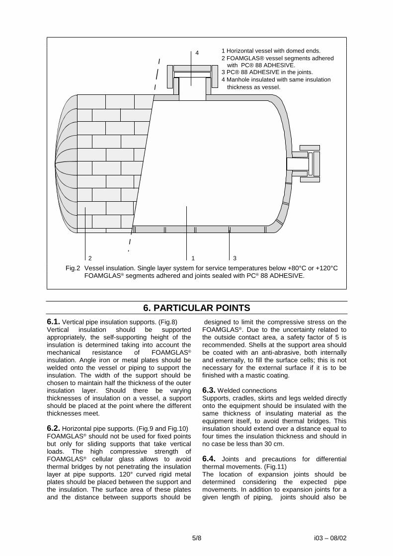
5/8 i03 – 08/02
12 3
4 1 Horizontal vessel with domed ends.2 FOAMGLAS® vessel segments adhered
with PC® 88 ADHESIVE.3 PC® 88 ADHESIVE in the joints.4 Manhole insulated with same insulation
thickness as vessel.
Fig.2 Vessel insulation. Single layer system for service temperatures below +80°C or +120°C FOAMGLAS® segments adhered and joints sealed with PC® 88 ADHESIVE.
6. PARTICULAR POINTS6.1. Vertical pipe insulation supports. (Fig.8) Vertical insulation should be supported appropriately, the self-supporting height of the insulation is determined taking into account the mechanical resistance of FOAMGLAS® insulation. Angle iron or metal plates should be welded onto the vessel or piping to support the insulation. The width of the support should be chosen to maintain half the thickness of the outer insulation layer. Should there be varying thicknesses of insulation on a vessel, a support should be placed at the point where the different thicknesses meet. 6.2. Horizontal pipe supports. (Fig.9 and Fig.10) FOAMGLAS® should not be used for fixed points but only for sliding supports that take vertical loads. The high compressive strength of FOAMGLAS® cellular glass allows to avoid thermal bridges by not penetrating the insulation layer at pipe supports. 120° curved rigid metal plates should be placed between the support and the insulation. The surface area of these plates and the distance between supports should be
designed to limit the compressive stress on the FOAMGLAS®. Due to the uncertainty related to the outside contact area, a safety factor of 5 is recommended. Shells at the support area should be coated with an anti-abrasive, both internally and externally, to fill the surface cells; this is not necessary for the external surface if it is to be finished with a mastic coating. 6.3. Welded connections Supports, cradles, skirts and legs welded directly onto the equipment should be insulated with the same thickness of insulating material as the equipment itself, to avoid thermal bridges. This insulation should extend over a distance equal to four times the insulation thickness and should in no case be less than 30 cm. 6.4. Joints and precautions for differential thermal movements. (Fig.11) The location of expansion joints should be determined considering the expected pipe movements. In addition to expansion joints for a given length of piping, joints should also be

6/8 i03 – 08/02
placed at any direction change in the piping. Expansion joints should be installed in the inner and outer insulation layers of horizontal piping and equipment. Vertical lines and equipment having support rings should have a joint immediately below each support ring. Each expansion joint should be filled with resilient insulation material. For multi-layer insulation systems a sliding compound should be applied between the insulation layers. This could be done with PITTSEAL® 444N if temperature
allows it. In order to avoid any water infiltration the expansion joint of the outer insulation layer should be covered with a butyl-rubber sheet (+/- 1.2 mm thick). This sheet should be sealed with PITTSEAL® 444N and fixed with steel straps. 6.5. Flashing Appropriate techniques and materials should be used to make the areas around nozzles, manholes and other protrusions watertight; this also applies to junctions of horizontal and vertical surfaces.
SCHEDULES & DETAILS
R
R = T
Pipe diameter
Insulation thickness
Cradle thickness
Minimum length of cradle
L (mm)
Inch min mm
max. mm
T mm
Maximum span in m 3.0 3.5 4.5 5.5 6.0
1/2 & 3/4 25 60
110
50 100 130
2.0 3.2 4.8
260 260 260
_ _ _
_ _ _
_ _ _
_ _ _
1 to 1 1/2 25 50
100
40 90
140
2.0 3.2 4.8
260 260 260
260 260 260
_ _ _
_ _ _
_ _ _
2 to 3 1/2 25 50 90
140
40 80
130 150
2.0 3.2 4.8 6.4
260 260 260 260
260 260 260 260
260 260 260 260
_ _ _ _
_ _ _ _
4 & 5 25 60
110
50 100 180
3.2 4.8 6.4
260 260 260
260 260 260
260 260 260
300 300 300
_ _ _
6 & 8 40 70
150
60 140 180
4.8 6.4 8.0
260 260 260
300 300 300
400 400 400
400 400 400
510 510 510
10 to 12 40
100 160
90 150 200
6.4 8.0 9.5
300 300 300
400 400 400
510 510 510
610 610 610
610 610 610
14 & 16 40 60
130 190
50 120 180 230
6.4 8.0 9.5
11.0
400 400 400 400
510 510 510 510
610 610 610 610
915 915 915 915
915 915 915 915
18 & 20 40 70
140 200
50 130 190
8.0 9.5
11.0 12.7
510 510 510 510
610 610 610 610
760 760 760 760
915 915 915 915
915 915 915 915
24 40 90
150
80 140 200
9.5 11.0 12.7
610 610 610
760 760 760
915 915 915
1070 1070 1070
1070 1070 1070
30 40 130
120 230
12.7 15.9
760 760
915 915
1070 1070
1220 1220
1370 1370
36 40 170
160 230
15.9 19.0
915 915
1070 1070
1220 1220
1370 1370
1530 1530
Fig. 9 SADDLES : FOAMGLAS® S3 insulation (compressive strength : 0.9 N/mm²).

7/8 i03 – 08/02
Thermal expansion of FOAMGLAS® cellular glass and metals based on 20°C ambient temperature.
Operating temperature
in °C
FOAMGLAS® cellular glass
mm/m
Carbon steel
mm/m
Stainless steel
mm/m
Aluminium
mm/m 0 -0.15 -0.23 -0.32 -0.45
50 +0.24 +0.34 +0.47 +0.65 100 +0.66 +0.91 +1.27 +1.74 150 +1.11 +1.50 +2.07 +2.87 200 +1.53 +2.12 +2.90 +4.05 300 +2.38 +3.36 +4.56 +6.44
7. SURFACE PROTECTION7.1. Metal jacket Apply sheets of aluminium, steel or aluminised steel, corrugated, flat or hammered to the external surface of the FOAMGLAS® cellular glass. If appropriate due to climatic or mechanical conditions, the external surface of the FOAMGLAS® insulation may first be coated with a single layer of PITTCOTE® 300 mastic that will be given enough drying time before jacket application.
7.2. Mastic coating. Apply a layer of PITTCOTE® 404 with a brush, trowel, gun or gloves. Embed the reinforcement fabric into the layer while it is still tacky. Make sure that the fabric does not tear or wrinkle. The overlap of fabric at joints should be 10 cm. When the first coat is dry to touch, apply a second layer of PITTCOTE® 404 mastic to completely cover the reinforcement fabric and provide a smooth uniform surface (see data sheet P31 for PITTCOTE® 404 and data sheets P50/P51 for PC® FABRIC 79). Ensure that the mastic is completely dry before applying any compatible paint.
1 2 3 1 Adhere +/- 120° of the circumference with small radius segments using PC® 88 ADHESIVE and give adhesive
time to set. Use tape to keep segments temporary in place. (Type SRS, see data sheet A16) 2 Finish the circumference with small radius segments and PC® 88 ADHESIVE when the adhesive of the 120° part
is completely dry. 3 Fill central part with radiused and bevelled segments (Type SHS, see data sheet A16).
Fig.3 Application method for tank head segments (Type SHS and SRS) on horizontal domed ends using PC® 88 ADHESIVE.
(a) 1 2 3 1 Preassemble about 3 small radius segments (Type SRS, see data sheet A16) together using temperature
resistant adhesive (a) like PC® HIGH TEMPERATURE ANTI-ABRASIVE. 2 Place small radius segments on vessel head and fix the preassembled segment using temporary rubber bends
and a floating ring in the centre. 3 Fill central part with radiused and bevelled segments (Type SHS, see data sheet A16) and finally fix with steel
straps. Fig.4 Application method for tank head segments (Type SHS and SRS) dry applied on
horizontal or vertical domed ends.

6
7
1 Pipe 2 FOAMGLAS® pipe shells 3 Vertical pipe support 4 Resilient insulating material (see 4.6) 5 Insulation fixing straps 6 Metal jacket 7 Butyl-rubber sheet ceiling outer expansion
joint. Fig.8 Vertical pipe support Single layer system for service
temperatures below 120°C
1 Piping 2 PC® HIGH TEMPERATURE ANTI-ABRASIVE
3 FOAMGLAS® insulation 4 PC® 88 ADHESIVE or other adhesive
(depends of service temperature) 5 Metal jacket 6 Steel saddle or collar Fig.10 Horizontal pipe supports or
hangers (no fixed points).
8
1 FOAMGLAS® cellular glass 2 Resilient insulation material 3 Sliding compound, PITTSEAL® 444N if
temperature allows it. 4 PITTCOTE® 300 cell filler (if specified - see
4.10.1.1) 5 Metal jacket 6 PITTSEAL® 444N 7 Butyl-rubber sheet ceiling outer expansion
joint 8 Metal straps Fig.11 Expansion joint.
Double layer system
While great care is taken in formulating specifications, we cannot be held responsible for them do to imponderables of each specific jobsite.
Pittsburgh Corning GmbH (Austria)
Pittsburgh Corning Nederland B.V.
Pittsburgh Corning Schweiz A.G.
FOAMGLAS® Península Ibérica
Pittsburgh Corning Scandinavia ab.
Deutsche Pittsburgh Corning GmbH
Pittsburgh Corning UK Ltd.
Pittsburgh Corning Norway
Pittsburgh Corning Italy
Pittsburgh Corning France S.A.
The innovative insulation people
Pittsburgh Corning Europe is also represented in: Croatia, Czech Republic, Denmark, Greece, Hungary, Poland, Rumania, Russian Federation, Slovak Republic, Slovenia, Ukraine and Africa.

i03-70 - 02/05 Page 1/4
I03-70 02/05
1. SERVICE CONDITIONS This specification covers the application of cellular glass insulation and accessory materials
to piping and equipment systems operating at above ambient temperatures.
2. PRELIMINARY CONDITIONS2.1. FOAMGLAS® slabs and pieces should be transported and stored vertically. Handle the packages with care. FOAMGLAS® insulation packages should be protected from the elements whilst in storage and not allowed to come into direct contact with the ground. 2.2. The surface to be insulated should be clean and free from all traces of grease, rust, dust and any foreign matter. The design engineer should decide whether a coat of anticorrosion paint is necessary, and the type of paint compatible with the service temperature and the adhesive used (if any). If he decides to specify a paint, the following rules should be observed: 2.2.1. The surface, if corroded or otherwise unsuitable, should be sandblasted before the possible anticorrosion coat is applied (SS-Sa-21/2). 2.2.2. Any surface imperfection should be wire brushed and then coated with a new layer of anticorrosion paint. The surface should be perfectly dry before the insulation is applied. 2.2.3. When an adhesive is used, the compatibility between the anticorrosion paint and
the adhesive should be verified before applying the insulation. 2.3. The surface and the materials used should be dry before and until the end of the application. 2.4. The application of FOAMGLAS® insulation on pipes or equipment should be done at ambient temperature (No application when piping or equipment are in service; special precautions should be taken and determined on a case by case basis). 2.5. The temperature limits of the accessory products should be respected during both storage and application. 2.6. Any deformation of the piping shall be avoided during application. For this purpose, the piping shall be supported at adequate intervals. 2.7. Hydrostatic, radiographic and other tests should be completed before the insulation is applied.
3. DETERMINATION OF THE REQUIRED INSULATION THICKNESS3.1. Heat transfers should be limited to acceptable values regarding both economic and functional aspects. 3.2. The surface temperature on the outer surface of the insulation should be kept under +60°C to prevent burns. For indoor applications a maximum surface temperature of +40°C is generally imposed to avoid excessive heating in closed spaces. 3.3.Service temperatures below +120°C (Fig.1). A one layer system is sufficient for this
temperature range. A double layer system should be applied when the recommended insulation thickness would be bigger than the maximum available thickness. 3.4. Service temperatures from +120°C to +430°C without rapid temperature variations (< 2 K/min). (Fig.2) If FOAMGLAS® is not restrained on the edges or by tight strapping, a sudden difference of about 120°C is acceptable between the two faces of an element.
APPLICATION OF FOAMGLAS® -TEROSTAT INSULATION SYSTEM
FOR ABOVE-AMBIENT PIPING AND EQUIPMENT SYSTEMS

i03-70 - 02/05 Page 2/4
A single or double layer system is generally sufficient for this temperature range.
4. MATERIALS USEDThe materials listed below are appropriate for this specification. 4.1. Insulation material The insulation should be FOAMGLAS® cellular glass (see data sheets A11 to A17) in preformed sections, radiused and bevelled lags or slabs. When ordering the insulation, service temperature should be indicated to allow the choice of suitable adhesive for the fabrication of pipe sections or radiused and bevelled lags. The insulation of standard 90° or 45° - bends (R=1.5 D) may be prefabricated in the factory, as for the straight pipe sections. Non-standard bends, T-pieces, reducers and other equipment should be insulated with pieces cut to size and adapted on site. Flanges and valves should be insulated with pipe shells of larger dimensions adapted on site and if necessary adhered with PC® 88 ADHESIVE to the inside of the outer casing. This allows for removal of the insulation and control of flanges and valves. 4.2. Anti-abrasive PC® LOW-TEMPERATURE ANTI ABRASIVE should be chosen for temperatures below 120°C and PC® HIGH-TEMPERATURE ANTI-ABRASIVE for temperatures above 120°C (see data sheet P21). This coating should normally only be applied when the piping is submitted to frequent and significant thermal movements or strong vibrations. The anti-abrasive coating should be applied onto the inner side of the FOAMGLAS® elements which are in contact with the metal pipe or the equipment. Never apply the anti-abrasive on the pipe itself. The anti-abrasive coating can be applied in the factory by spraying or on site by brushing a thin layer on the inside of the insulation layer. The anti-abrasive should be completely dry before applying the insulation material. 4.3. Joint sealant To take full benefit of the complete water-vapour tightness of FOAMGLAS® insulation, all joints of the outer layer or of the only layer must be sealed with appropriate sealers, especially if service temperature is below ambient. Joint sealant for above ambient applications shall be TEROSTAT PC. This material shall also be used to seal metal jacket laps and protrusions.
4.4. Adhesive. For vessels with operating temperatures up to +80°C or +120°C an adhered system using PC® 88 ADHESIVE, a two-component adhesive based on bitumen modified with polyurethane (see data sheet P05) is possible. Please consult Pittsburgh Corning. If low working stresses are expected PC® 88 ADHESIVE can be used up to +120°C else the maximum operating temperature is limited up to +80°C. 4.5. Resilient insulating material. Low density glass wool. 4.6. Tape Self-adhesive tape, reinforced with glass fabric. Or: Aluminium lined butyl rubber self-adhesive tape 4.7. Insulation fixing straps The straps shall be in AISI type 304 (BSI 304 S16) stainless steel and should measure 12 mm wide x 0.4 mm thick or 19 mm wide x 0.5 mm thick depending on the dimensions of the vessels or piping. Wire to fix FOAMGLAS® shells or segments should be avoided, due to the wire cutting of the FOAMGLAS® surface. 4.8. Finishes and Claddings 4.8.1. Weather resistant mastic Foamglas-Terostat elements will be supplied, (Foamglas elements, covered with a factory applied layer of Terostat PC); Terostat PC shall be supplied in suitable containers for on the job finishing. 4.8.2. Metal jacket for covering. A metal jacket finish is only required in high mechanical-abuse areas. The metal jacket should be of suitable thickness. It is recommended to fix the jacket by banding it, 3 stainless steel straps per meter run. . 4.8.3 Expansion joint covering. Butyl-rubber sheets of +/- 1.2 mm thick should be used.
5. APPLICATION

i03-70 -02/05 Page 3/4 05/04
5.1. The FOAMGLAS® shells shall be applied with staggered and carefully butted joints. Each section of inner layer shall be tightly fixed in place with two self-adhesive, glass-fibre reinforced tapes, applied with minimum overlap of 150 mm, or stainless steel straps. All the joints shall be carefully adjusted to avoid any voids which can be eliminated by refitting the shells or by replacing them. Joint width to be 2-3mm. 5.1.1 Single layer applications and outer layer
of multiple layer applications will have Terostat PC applied to all longitudinal and circumferential joints. The sealant is applied by cartridge to one of the mating surfaces, at the outmost outer side of the joint, to give a bead of 7 mm diameter. Foamglas will be tensioned firmly using a band tensioning system. Terostat PC squeezed out of the joint is to be smoothed flush with the factory applied Terostat PC surface ( appropriate tools like flexible spatula, covered with a soapy water solution, will enable a smooth surface to be achieved and avoid drag marks). Insulation fixing straps or tape, if required, shall be installed after having smoothed the joints.
5.1.2 A thin bead of TEROSTAT PC may, if
necessary, be applied to the outside of the joint after completion of strapping and smoothed in to ensure a level joint.
5.1.3 Terostat PC may be field applied to
fittings and other field fabricated and irregular shapes.
5.2. Joints and precautions for differential thermal movements. (Fig.3)
The location of expansion joints should be determined considering the expected pipe movements. In addition to expansion joints for a given length of piping, joints should also be placed at any direction change in the piping. Expansion joints should be installed in the inner and outer insulation layers of horizontal piping and equipment.
Vertical lines and equipment having support rings should have a joint immediately below each support ring. Each expansion joint should be filled with resilient insulation material. For multi-layer insulation systems a sliding compound should be applied between the insulation layers. This could be done with PITTSEAL® 444 if temperature allows it. In order to avoid any water infiltration the expansion joint of the outer insulation layer should be covered with a butyl-rubber sheet (+/- 1.2 mm thick). This sheet should be sealed with Terostat PC-FR and fixed with steel straps. 5.3. Flashing Appropriate techniques and materials should be used to make the areas around nozzles, manholes and other protrusions watertight; this also applies to junctions of horizontal and vertical surfaces
a a
1 PC® LOW TEMPERATURE ANTI-ABRASIVE (if specified - see 4.2.) 2 FOAMGLAS® cellular glass 3 TEROSTAT PC joint sealant 4 Metal fixing strap (if required) 5 TEROSTAT PC (factory applied) 6 Metal jacket (if specified) Fig.1 Single layer systems for service temperatures above ambient to +120°C.

i03-70 - 02/05 Page 4/4
1 2 3 4 5 6 7a a
1 PC® ANTI-ABRASIVE (if specified - see 4.3.) 2 FOAMGLAS® insulation 3 Tape or metal fixing straps 4 TEROSTAT PC sealant in the joints of the outer layer 5 Metal fixing straps (if required) 6 TEROSTAT PC (factory applied) 7 Metal jacket (if specified) Fig.2 Double layer systems for service temperatures from +120°C upwards
8 1 FOAMGLAS® cellular glass 2 Resilient insulation material 3 Sliding compound, PITTSEAL® 444 if
temperature allows it. 4 TEROSTAT PC (factory applied) 5 Metal jacket (if specified) 6 Terostat PC 7 Butyl-rubber sheet sealing outer expansion
joint 8 Metal straps Fig.3 Expansion joint.
Double layer system
Application of TEROSTAT to joints
Application of shells to pipe
Banding and finishing
Thermal expansion of FOAMGLAS® cellular glass and metals based on 20°C ambient temperature.
Operating temperature in °C
FOAMGLAS® mm/m
Carbon steel mm/m
Stainless steel mm/m
Aluminium mm/m
0 -0.15 -0.23 -0.32 -0.45 50 +0.24 +0.34 +0.47 +0.65
100 +0.66 +0.91 +1.27 +1.74 150 +1.11 +1.50 +2.07 +2.87 200 +1.53 +2.12 +2.90 +4.05 300 +2.38 +3.36 +4.56 +6.44

1/8 i04 – 08/02
i04
08/02
1. SERVICE CONDITIONS This specification applies to the insulation of piping and equipment installed in the open air or under cover with a service temperature varying between -180°C and +250°C.
These specifications are general in nature. For specific applications, contact your Pittsburgh Corning representative. The final application procedure is the responsibility of the designer and/or owner.
2. PRELIMINARY CONDITIONS2.1. FOAMGLAS® slabs and pieces should be transported and stored vertically. Handle the packages with care. FOAMGLAS® insulation packages should be protected from the elements whilst in storage and not allowed to come into direct contact with the ground. 2.2. The surface to be insulated should be clean and free from all traces of grease, rust, dust and any foreign matter. The design engineer should decide whether a coat of anticorrosion paint is necessary, and the type of paint compatible with the service temperature, the adhesive used (if any) and the anti-abrasive. If he decides to specify a paint, the following rules should be observed: 2.2.1. The surface, if corroded or otherwise unsuitable, should be sandblasted before the possible anticorrosion coat is applied (SS-Sa-2 1/2). 2.2.2. Any surface imperfection should be wire brushed and then coated with a new layer of
anticorrosion paint. The surface should be perfectly dry before applying the insulation. 2.2.3. When an adhesive is used, the compatibility between the anticorrosion paint and the adhesive should be verified before applying the insulation. 2.3. The surface and the materials to be used should be dry before and during application, and should remain dry until start up. 2.4. The application of FOAMGLAS® insulation on pipes or equipment should be done at ambient temperature (no application when piping or equipment is in service). 2.5. The temperature limits of the accessory products should be respected during both storage and application. 2.6. Hydrostatic, radiographic and other tests should be completed before applying the insulation.
3. DETERMINATION OF THE REQUIRED INSULATION THICKNESS3.1. Heat transfers should be limited to acceptable values regarding both economic and functional aspects. 3.2. Formation of condensation on the external surface of the insulation should be limited. 3.3. The thickness of the different insulation layers should be chosen according to the temperature range of the assembly material used during fabrication as well as the sealing compound. Example : with PITTSEAL® 444N, the insulation layers should be chosen in such a way that the interface temperature of the external layer is not lower than -50°C and not higher than +80°C.
Please consult Pittsburgh Corning’s Technical Service for other temperatures. 3.4. The surface temperature on the outer surface of the insulation should be kept below +60°C to prevent burns. For indoor applications, a maximum surface temperature of +40°C is strongly recommended to avoid excessive heating in closed spaces. 3.5. Calculation of estimated heat transmission in steady state as well as determination of surface temperature can be prepared by Pittsburgh Corning’s Technical Service.
DUAL TEMPERATURE
PIPING AND EQUIPMENT

2/8 i04 – 08/02
4. USED MATERIALS4.1. Insulation material. The insulation should be FOAMGLAS® cellular glass (see data sheet A01 to A16) in preformed sections, radiused and bevelled lags or slabs. When ordering the insulation, service temperature should be indicated to allow the choice of a suitable adhesive when fabricating pipe sections or radiused and bevelled lags. The insulation of standard 90° or 45° - bends (R = 1.5 D) can also be prefabricated in the factory. Non-standard bends, T-pieces, reducers and other equipment should be insulated with pieces cut to size on site. Flanges and valves should be insulated with pipe shells of larger dimensions adapted on site and possibly adhered onto the inside of the outer casing with PC® 88 ADHESIVE. This allows for removal of the insulation and control of flanges and valves. 4.2. Anti-corrosion layer. If PC® 88 ADHESIVE is used as an adhesive, the anti-corrosion layer should not be based on bitumen, tar, silicone or polyurethane. Zinc chromates or similar coatings are generally compatible. Compatibility should be verified before applying the insulation. 4.3. Anti-abrasive. LOW TEMPERATURE ANTI-ABRASIVE should be chosen for temperatures from -180°C to 120°C (see data sheet P20) and PC® HIGH TEMPERATURE ANTI-ABRASIVE for temperatures above 120°C or below -180°C (see data sheet P21). This coating should be applied only when the piping is submitted to frequent and significant thermal movements or strong vibrations. The anti-abrasive coating should be applied onto the inner side of the FOAMGLAS® elements which will be in contact with the metal pipe or equipment. Never apply the anti-abrasive on the pipe itself. The anti-abrasive can be sprayed at the factory or applied on site by brushing a thin layer onto the inside of the insulation. The anti-abrasive should be completely dry before the insulation material is applied. 4.4. Joint sealant. To take full benefit of the complete tightness of FOAMGLAS® insulation all the joints of the outer layer or of the only layer must be sealed with appropriate sealers. Most suitable FOAMGLAS® sealers are butyl based products such as PITTSEAL® 444N. PITTSEAL® 444N is a one-component sealer based on polyisobutylene (see data sheet P41). PITTSEAL® 444N should be applied with a caulking cartridge or an extrusion gun in beads to one of the jointing edges.
4.5. Adhesive. Great care should be taken when selecting an adhesive for dual temperature. At temperatures down to -50°C, the adhesive should, after curing, remain flexible and absorb mechanical and thermal stresses. Down to -50°C and up to 80°C, this can be done with PC® 88 ADHESIVE, a two-component adhesive based on bitumen modified with polyurethane (see data sheet P05). If low working stresses are expected, PC® 88 ADHESIVE can be used up to +120°C otherwise the maximum operating temperature is limited to +80°C. The temperature of the metal surface should not be lower than +5°C during application. If rapid adhesion is needed, the surface to be insulated should be maintained at temperatures between +20°C and +35°C. 4.6. Resilient insulating material. Low density glass fibre insulation, minimal temperature range from -180°C to +250°C. 4.7. Insulation fixing straps. The straps should be in AISI type 304 (BSI 304 S16) stainless steel and should measure 12.7 mm wide x 0.5 mm thick. Wire to fix FOAMGLAS® shells or segments should be avoided, due to the wire cutting of the FOAMGLAS® surface. 4.8. Tape. Self-adhesive glass fibre reinforced tape. 4.9. Movement joint covering. Butyl-rubber sheets of +/- 1.2 mm thick should be used. 4.10. Finishes and jackets. A metal jacket or a flexible mastic coating should be chosen. 4.10.1. Metal jacket as finishing cover. 4.10.1.1. Cell filler for outdoor applications. In high wind areas or when a mechanically strong outer finish is needed (Possible foot traffic on the pipes) a cell filler is recommended for outdoor applications. The cut surface cells may be filled with PITTCOTE® 300 (see data sheet P30). Coverage as a cell filler is about 1.5 kg/m². 4.10.1.2. The metal jacket should be aluminium, steel or aluminised steel sheets, corrugated, flat or hammered, of suitable thickness. The easiest way to apply the jacket is to band it. Pop rivets or screws may also be used after having held the jacket tightly with temporary bands. A cushion layer of fibrous insulation between FOAMGLAS®

3/8 i04 – 08/02
insulation and the jacket should be avoided. This top layer will absorb the ambient moisture during humid weather and could result in corroding the metal jacket. 4.10.2. Flexible mastic with fabric reinforcement. 4.10.2.1. PITTCOTE® 404 coating (see data sheet P31) is an acrylic waterborne mastic giving excellent results in aggressive atmospheres. It is not a vapour barrier but a weather barrier.
Regular control and maintenance of the mastic finish is recommended. 4.10.2.2. Reinforcement. The reinforcement should be PC® FABRIC 79P (polyester) (see data sheet P50). This product together with PITTCOTE® 404 provides a very flexible outer finish. PC® FABRIC 79G (glass) (see data sheet P51) should be avoided if important differential thermal movements are expected.
5. INSULATION SYSTEMSService temperature of the pipe or equipment will help to determine the insulation system as well as the insulation thickness. 5.1. Service temperatures ranging from +80°C to -50°C without rapid temperature variations (< 2 K/min). (Fig.1) A single layer system is sufficient for this temperature range. A double layer system should be applied when the recommended insulation thickness is greater than the maximum available thickness (see data sheets A11 to A16 regarding thicknesses). 5.1.1. Piping, elbows and fittings. Shells and segments appropriate to the shape of the surface to be insulated should be applied with staggered joints and the joints filled with PITTSEAL® 444N or any other suitable mastic. Care should be taken to ensure that the joints are tightly butted when the mastic is applied. This or another mastic should not be used to fill joints that are too wide as a result of poor fitting. After applying the shells or segments to the pipe or equipment they will be held in place by means of 2 steel straps per shell or segment. 5.1.2. Vessels. (Fig.2 and Fig.3) Segments appropriate to the shape of the surface to be insulated should be applied with staggered joints. Staggering the segments is not needed for vessel heads or other irregular forms. Segments will be adhered and joints filled with PC® 88 ADHESIVE. Temporary banding is needed to give PC® 88 ADHESIVE time to set. Excess adhesive running out of the joints should be removed before it sets. Extra steel straps are not needed when using PC® 88 ADHESIVE.
a a
b bb 1 LOW TEMPERATURE ANTI-ABRASIVE (if specified - see 4.3.) 2 FOAMGLAS® cellular glass 3 PITTSEAL® 444N sealer 4 Metal fixing strap 5a PITTCOTE® 300 cell filler (if specified - see 4.10.1.1.) 5b PC® FABRIC 79P reinforcement 6a Metal jacket 6b PITTCOTE® 404 Fig.1 Single layer systems for service temperatures from +80°C to -50°C.
5.2. Service temperatures ranging from +250°C to -180°C without rapid temperature variations (< 2 K/min). (Fig.4) Piping, elbows, fittings and vessels. A double layer system is generally sufficient for this temperature range. With PITTSEAL® 444N the insulation layers should be chosen in such a way that the interface temperature of the two layers is not lower than –50°C and not higher than +80°C. Depending of weather conditions, a triple layer system may be needed.

4/8 i04 – 08/02
Shells and segments appropriate to the shape of the surface to be insulated should be applied with joints that are staggered regarding each other and to the second layer. The first layer should be dry applied and fixed with tape or steel straps. Depending on vessel diameter, it could be possible that the first layer has to be fixed with steel straps.
1 2 3 4 5 6 7a a
1 2 3 4 5 6 77b b b 1 PC® HIGH TEMPERATURE ANTI- ABRASIVE (if specified - see 4.3.) 2 FOAMGLAS® insulation 3 Tape or metal fixing straps 4 PITTSEAL® 444N sealant in the joints of the outer layer 5 Metal fixing straps 6a PITTCOTE® 300 cell filler (if specified - see 4.10.1.1.) 6b PC® FABRIC 79 reinforcement 7a Metal jacket 7b PITTCOTE® 404 Fig.4 Double layer systems for service temperatures from +250°C to -180°C The joints of the second layer should be filled with PITTSEAL® 444N or any other suitable mastic. Care should be taken to ensure that the joints are tightly butted when the mastic or adhesive is applied. This or another mastic should not be used to fill joints that are too wide as a result of poor fitting. The second layer will always be held in place by means of 2 steel straps per shell or segment. The insulation of the bottom heads, manholes and other individual items should also be fixed in place with steel straps. These straps should be attached to support rings welded onto the body of the vessel.
5.3. Service temperatures ranging from +250°C to -180°C with rapid temperature variations (>2K/min). (Fig.5) Piping, elbows, fittings and vessels. The thickness and the number of layers is the same as for normal operation. Some extra precautions should be taken in order to limit the effects of thermoshocks that could result in some hairline cracks in the insulation layer. These cracks do not reduce the FOAMGLAS® insulation value but the insulation must be installed in such a way that negative consequences are avoided. The inner layer should be coated with a layer of PC® HIGH TEMPERATURE ANTI-ABRASIVE into which PC® FABRIC 79G has been embedded. The second layer can be dry applied over it as soon as the PC® HIGH TEMPERATURE ANTI-ABRASIVE is dry. The joints of the second layer should be filled with PITTSEAL® 444N or any other suitable mastic. Care should be taken to ensure that the joints are tightly butted when the mastic or adhesive is applied. This or another mastic should not be used to fill joints that are too wide as a result of poor fitting. External insulation layer should always be fixed with steel straps.
1 2 3 4 5 6 72 8
1 PC® HIGH TEMPERATURE ANTI-ABRASIVE (if specified - see 4.3.) 2 FOAMGLAS® insulation 3 PC® HIGH TEMPERATURE ANTI-ABRASIVE 4 PC® FABRIC 79 reinforcement 5 Metal fixing straps 6 PITTCOTE® 300 cell filler (if specified - see
4.10.1.1.) 7 Metal jacket 8 PITTSEAL® 444N Fig.5 Double layer system for service
temperatures from 250°C to -180°C with rapid temperature variations.

5/8 i04 – 08/02
1 2 3
4 1 Horizontal vessel with domed ends. 2 FOAMGLAS® vessel segments adhered
with PC® 88 ADHESIVE. 3 PC® 88 ADHESIVE in the joints. 4 Manhole insulated with the same
insulation thickness as the vessel.
Fig.2 Vessel insulation. Single layer system for service temperatures from +80°C to -50°C FOAMGLAS® segments adhered and joints sealed with PC® 88 ADHESIVE.
6. PARTICULAR POINTS6.1. Vertical pipe insulation supports. (Fig.6) Vertical insulation should be appropriately supported, the self-supporting height of the insulation is determined taking into account the mechanical resistance of FOAMGLAS® insulation. Angle iron or metal plates should be welded onto the vessel or piping to support the insulation. The width of the support should be chosen to maintain half the thickness of the outer insulation layer. Should there be various insulation thicknesses on a vessel, a support should be placed where the different thicknesses meet. 6.2. Horizontal pipe supports. (Fig.7 and Fig.8) FOAMGLAS® should not be used for fixed points but only for sliding supports that take vertical loads. Thanks to the high compressive strength of FOAMGLAS® cellular glass, thermal bridges can be avoided, no penetration of the insulation layer being possible at pipe supports. 120° curved rigid metal plates should be placed between the support and the insulation. The surface area of these plates and the distance between supports should be designed to limit compressive stress on FOAMGLAS®. Due to the
uncertainty related to the outside contact area, a safety factor of 5 is recommended. Shells at the support area should be coated with an anti-abrasive, both internally and externally, to fill the surface cells; this is not necessary for the external surface if it is finished with a mastic coating. 6.3. Welded connections. Supports, cradles, skirts and legs welded directly onto the equipment should be insulated with the same insulation thickness as the equipment itself, to avoid thermal bridges. This insulation should extend over a distance equal to four times the insulation thickness and should in no case be less than 30 cm. 6.4. Joints and precautions for differential thermal movements. (Fig.9) The location of movement joints should depend on the expected pipe movements. In addition to movement joints for a given length of piping, joints should also be placed at every direction change in the piping. Movement joints should be installed in the inner and outer insulation layers of horizontal piping and equipment.
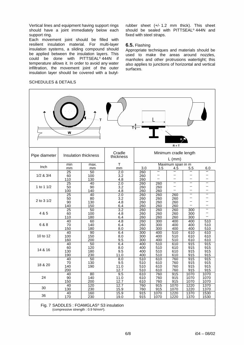
6/8 i04 – 08/02
Vertical lines and equipment having support rings should have a joint immediately below each support ring. Each movement joint should be filled with resilient insulation material. For multi-layer insulation systems, a sliding compound should be applied between the insulation layers. This could be done with PITTSEAL® 444N if temperature allows it. In order to avoid any water infiltration, the movement joint of the outer insulation layer should be covered with a butyl-
rubber sheet (+/- 1.2 mm thick). This sheet should be sealed with PITTSEAL® 444N and fixed with steel straps. 6.5. Flashing Appropriate techniques and materials should be used to make the areas around nozzles, manholes and other protrusions watertight; this also applies to junctions of horizontal and vertical surfaces.
SCHEDULES & DETAILS
R
R = T
Pipe diameter
Insulation thickness
Cradle thickness
Minimum cradle length
L (mm)
Inch min mm
max. mm
T mm
Maximum span in m 3.0 3.5 4.5 5.5 6.0
1/2 & 3/4 25 60
110
50 100 130
2.0 3.2 4.8
260 260 260
_ _ _
_ _ _
_ _ _
_ _ _
1 to 1 1/2 25 50
100
40 90
140
2.0 3.2 4.8
260 260 260
260 260 260
_ _ _
_ _ _
_ _ _
2 to 3 1/2 25 50 90
140
40 80
130 150
2.0 3.2 4.8 6.4
260 260 260 260
260 260 260 260
260 260 260 260
_ _ _ _
_ _ _ _
4 & 5 25 60
110
50 100 180
3.2 4.8 6.4
260 260 260
260 260 260
260 260 260
300 300 300
_ _ _
6 & 8 40 70
150
60 140 180
4.8 6.4 8.0
260 260 260
300 300 300
400 400 400
400 400 400
510 510 510
10 to 12 40
100 160
90 150 200
6.4 8.0 9.5
300 300 300
400 400 400
510 510 510
610 610 610
610 610 610
14 & 16 40 60
130 190
50 120 180 230
6.4 8.0 9.5
11.0
400 400 400 400
510 510 510 510
610 610 610 610
915 915 915 915
915 915 915 915
18 & 20 40 70
140 200
50 130 190
8.0 9.5
11.0 12.7
510 510 510 510
610 610 610 610
760 760 760 760
915 915 915 915
915 915 915 915
24 40 90
150
80 140 200
9.5 11.0 12.7
610 610 610
760 760 760
915 915 915
1070 1070 1070
1070 1070 1070
30 40 130
120 230
12.7 15.9
760 760
915 915
1070 1070
1220 1220
1370 1370
36 40 170
160 230
15.9 19.0
915 915
1070 1070
1220 1220
1370 1370
1530 1530
Fig. 7 SADDLES : FOAMGLAS® S3 insulation (compressive strength : 0.9 N/mm²).

7/8 i04 – 08/02
Thermal movement of FOAMGLAS® cellular glass and metals based on 20°C ambient temperature.
Operating temperature
in °C
FOAMGLAS® cellular glass
mm/m
Carbon steel
mm/m
Stainless steel
mm/m
Aluminium
mm/m -200 -1.53 -1.94 -2.83 -3.93 -150 -1.21 -1.68 -2.37 -3.38 -100 -0.89 -1.26 -1.76 -2.52 -50 -0.53 -0.77 -1.06 -1.53
0 -0.15 -0.23 -0.32 -0.45 50 +0.26 +0.34 +0.47 +0.65
100 +0.70 +0.91 +1.27 +1.74 150 +1.15 +1.50 +2.07 +2.87 200 +1.62 +2.12 +2.90 +4.05 300 +2.59 +3.36 +4.56 +6.44
7. SURFACE PROTECTION7.1. Metal jacket Apply sheets of aluminium, steel or aluminised steel, corrugated, flat or hammered to the external surface of the FOAMGLAS® cellular glass. If appropriate due to climatic or mechanical conditions, the external surface of the FOAMGLAS® insulation may first be coated with a single layer of PITTCOTE® 300 mastic that will be given enough drying time before jacket application.
7.2. Mastic coating. Apply a layer of PITTCOTE® 404 with a brush, a trowel, a gun or gloves. Embed the reinforcement fabric into the layer while it is still tacky. Make sure that the fabric does not tear or wrinkle. The overlap of fabric at joints should be 10 cm. When the first coat is dry to touch, apply a second layer of PITTCOTE® 404 mastic to completely cover the reinforcement fabric and provide a smooth uniform surface (see data sheet P31 for PITTCOTE® 404 and data sheets P50/P51 for PC® FABRIC 79). Ensure that the mastic is completely dry before applying any compatible paint.
1 2 3 1 Adhere +/- 120° of the circumference with small radius segments using PC® 88 ADHESIVE and give adhesive
time to set. Use tape to keep segments temporary in place. (Type SRS, see data sheet A16) 2 Finish the circumference with small radius segments and PC® 88 ADHESIVE when the adhesive of the 120° part
is completely dry. 3 Fill central part with radiused and bevelled segments (Type SHS, see data sheet A16). Fig.3 Application method for tank head segments (Type SHS and SRS) on horizontal
domed ends using PC® 88 ADHESIVE.

7
8
6
1 Pipe 2 FOAMGLAS® pipe shells 3 PITTSEAL® 444N 4 Metal jacket 5 Vertical pipe support 6 Resilient insulating material (see 4.6) 7 Butyl-rubber sheet covering the outer
movement joint. 8 Insulation fixing straps Fig.6 Vertical pipe support Single layer system for service
temperatures from -50°C to +80°C
1 Piping 2 Anti abrasive (depends on service temperature) 3 FOAMGLAS® insulation 4 PC® 88 ADHESIVE or other adhesive
(depends on service temperature) 5 Metal jacket 6 Steel saddle or collar Fig.8 Horizontal pipe supports or
hangers (no fixed points).
8
1 FOAMGLAS® cellular glass 2 Resilient insulation material 3 Sliding compound, PITTSEAL® 444N if
temperature allows it. 4 PITTCOTE® 300 cell filler (if specified - see
4.10.1.1) 5 Metal jacket 6 PITTSEAL® 444N 7 Butyl-rubber sheet covering the outer
movement joint 8 Metal straps Fig.9 Movement joint.
Double layer system
While great care is taken in formulating specifications, we cannot be held responsible for them due to imponderables on each specific jobsite.
Pittsburgh Corning GmbH (Austria)
Pittsburgh Corning Nederland B.V.
Pittsburgh Corning Schweiz A.G.
FOAMGLAS® Península Ibérica
Pittsburgh Corning Scandinavia ab.
Deutsche Pittsburgh Corning GmbH
Pittsburgh Corning UK Ltd.
Pittsburgh Corning Norway
Pittsburgh Corning Italy
Pittsburgh Corning France S.A.
The innovative insulation people
Pittsburgh Corning Europe is also represented in: Croatia, Czech Republic, Denmark, Greece, Hungary, Poland, Rumania, Russian Federation, Slovak Republic, Slovenia, Ukraine and Africa.

I06-08/02 1/4
i06
08/02
1. SERVICE CONDITIONS This specification applies to the insulation of walls and roofs of cylindrical storage tanks with vertical axes where service temperature is
between +20°C and -50°C. Tanks covered by this specification includes single tanks with or without bund wall and double containment tanks.
2. PRELIMINARY CONDITIONS2.1. FOAMGLAS® slabs and pieces should be transported and stored vertically. Handle the packages with care. FOAMGLAS® insulation packages should be protected from the elements whilst in storage and not allowed to come into direct contact with the ground. 2.2. The surface to be insulated should be clean and free from all traces of grease, rust, dust and any foreign matter. The design engineer should decide whether a coat of anticorrosion paint is necessary, and the type of paint compatible with the service temperature and the adhesive used (if any). If he decides to specify a paint, the following rules should be observed: 2.2.1. The surface, if corroded or other wise unsuitable, should be sandblasted before the possible anticorrosion coat is applied (SS-Sa-2 1/2). 2.2.2. Any surface imperfection should be wire brushed and then coated with a new layer of anticorrosion paint. The surface should be perfectly dry before the insulation is applied. 2.2.3. The compatibility between the anticorrosion paint and the adhesive should be
verified before the insulation is applied.(see 4.2 regarding compatible products) 2.3. The surface and the materials used should be dry before and until the end of the application, and should remain dry until start up.. 2.4. The application of FOAMGLAS® insulation should be done at ambient temperature (no application when tank is in service without precautions. Do be determined in each case.). 2.5. The temperature limits of the accessory products should be respected during both storage and application. 2.6. Hydrostatic, radiographic and other tests should be completed before the insulation is applied. 2.7. Double containment tank with liner. The design engineer should decide the type of liner used. The FOAMGLAS®/PC® 88 ADHESIVE compact system can be applied on steel liner. On coating liner the compatibility with PC® 88 ADHESIVE should be verified. Compatible coating liner : Max Perles.
3. DETERMINATION OF INSULATION THICKNESS REQUIRED3.1. Heat transfers should be limited to acceptable values regarding both economic and functional aspects (maximum boil-off rate). 3.2. The formation of condensation on the external surface of the insulation should be limited.
3.3. The thickness is determined according to the thermal requirements that apply to the specific case.
VERTICAL STORAGE
TANK WALLS AND ROOFS

2/4 i06-08/02
The following values can be taken as guidance only, in general conditions:
Products Temperature (°C) Thickness (cm) Butane -1 5-10 Ammonia -33 10-15 Propane -44 15-20 Propylene -47 15-25
4. MATERIALS USED4.1. Insulation material The insulation should be FOAMGLAS® cellular glass (see data sheets A02 and A03). If necessary, the slabs should be adjusted by abrasion to fit the curvature of the wall or roof. Radiused and bevelled slabs of appropriate shape can be fabricated by Pittsburgh Corning. 4.2. Anti-corrosion layer The anti-corrosion layer should not be based on bitumen, tar, silicone or polyurethane. Zinc chromates or similar coatings are generally compatible. The compatibility should be verified before insulation is applied. Example of paints compatible with PC® 88 ADHESIVE are: - READLEAD EPOXY PRIMER (GOODGLASS WALL & Co.) - STRATHCLYDE PA 10 RED OXIDE PRIMER - COLTURIET SEALER (SIGMA COATINGS) 4.3. Adhesive. Care should be taken in selecting an adhesive for cold temperatures. At temperatures down to -50°C the adhesive should, after curing, remain flexible and absorb mechanical and thermal stresses. Down to -50°C this can be done with PC® 88 ADHESIVE, a two-component adhesive based on bitumen modified with polyurethane (see data sheet P05). The temperature of the metal surface should not be lower than +5°C during application. If rapid adhesion is needed the surface to be insulated should be maintained between +20°C and +35°C. 4.4. Joint sealer Usually no sealer is needed except for some particular locations such as inlets, outlets and movement joints between wall and fixed roof. PITTSEAL® 444N is a one-component sealer based on polyisobutylene (see data sheet P41). Temperature range -50°C to +80°C. It should be applied with caulking cartridge or an extrusion gun. 4.5. Resilient insulating material. Low density glass wool or neoprene foam insulation.
4.6. Insulation fixing straps. In general no straps are needed when adhering FOAMGLAS® with PC® 88 ADHESIVE Any optional straps should be in AISI type 304 (BSI 304 S16) stainless steel and should measure 19 mm wide x 0.8 mm thick. 4.7. Contraction and movement joint covering. Butyl-rubber sheets of +/- 1.2 mm thick should be used. 4.8. Finishes and jackets. A metal jacket or a flexible mastic coating should be chosen. 4.8.1. Metal jacket as finishing cover. 4.8.1.1. Cell filler for single tanks without bund wall. In high wind areas or when a mechanical strong outer finish is needed the cut surface cells may be filled with PITTCOTE® 300 (see data sheet P30) . PITTCOTE® 300 coverage as a cell filler is about 1.5 kg/m². 4.8.1.2. The metal jacket should consist of corrugated metal sheets of suitable thickness. The jacket is applied in long lengths placed vertically with Z metallic supports and metal straps to hold them in place. 4.8.2. Flexible mastic with fabric reinforcement. 4.8.2.1. PITTCOTE® 404 coating (see data sheet P31) is an acrylic water borne mastic giving excellent results in aggressive atmospheres. It is not a vapour barrier but a weather barrier. A regular control and maintenance of mastic finish is recommended. 4.8.2.2. Reinforcement. The reinforcement should be PC® FABRIC 79P (polyester) (see data sheet P50). This product together with PITTCOTE® 404 offers a very flexible outer finish. PC® FABRIC 79G (glass) (see data sheet P51) should be avoided if important differential thermal movements are expected.

3/4 i06 – 08/02
5. INSULATION SYSTEMSService temperature and the type of tank will guide requirements made on the insulation system as well as the insulation thickness. 5.1. Tank wall insulation. Depending on the type of tank FOAMGLAS® insulation can be applied on the outside of the inner or only steel tank or on the inner surface of the outer tank. (Fig.1) Differences from geometrical, cylindrical form of the wall or steel liner shall not exceed 10 mm for a distance of 2 meters. Local irregularities, due for instance to welding, may be exceed this value provided that they are adequately treated. The tank should be protected from the elements to avoid any water penetration or condensation during application of the insulation. The PC® 88 ADHESIVE should be prepared according to the manufacturer's instructions (see data sheet P05). It should be applied with a 6 mm notched trowel all-over the slab surface to be glued and two adjacent edges. PC® 88 ADHESIVE will act as a vapour barrier in the joints, which should be completely filled. FOAMGLAS® slabs should be laid in rows, starting at the bottom of the tank. The horizontal and vertical joints in each layer of insulation should be aligned. This alignment of joints filled with PC® 88 ADHESIVE acts as small expansion/contraction joints. Care should be taken that the joint thickness ranges from 2 to 3mm (Fig.2) Each slab should be laid so that it is pressed firmly against the previous one, thus making the joints perfectly water and water vapour tight. Surplus adhesive exuding from joints should be removed before adhesive sets. Should any slabs be broken during application, the resulting joints should be filled with PC® 88 ADHESIVE. Steps or irregularities can be matched by presenting the
FOAMGLAS® slab dry to the surface and shaping it locally by abrasion. An alternative method consists in placing a joint in front of the local irregularity. Unprotected edges of slabs should be covered with a layer of PC® 88 ADHESIVE, whenever work is interrupted. It is recommended that work be interrupted if there is rain and that edges should be protected as indicated above. This protective layer should be removed when work is recommenced. A movement joint should be provided at the wall/roof junction. It should allow differential movement when tank is put into service. (Fig.3) Any connection to the tank should be designed to allow differential movement between the tank, the insulation and the connection (piping, stairs, inlet, outlet, etc.). Manholes should be insulated with the same insulation thickness as the tank. Anchoring systems should be enclosed with resilient insulating material that will allow them to move. The complete system should be covered by an additional layer of FOAMGLAS®, applied with adhesive to prevent any penetration of water or water vapour. 5.2. Tank roof insulation (fixed roof). FOAMGLAS® insulation should be applied to the roof using PC® 88 ADHESIVE. The application technique is identical as for the walls. The best way to start insulation of a large tank roof is to divide it in 4 or 6 parts and fill each part with slabs adjusted to the curvature of the roof. With this method cutting is reduced to a minimum. If there is rain the roof insulation should be protected to avoid that water should be trapped between insulation and tank surface or that water should stay in open surface cells of the already applied slabs.
a
1 2 3 1 Insulation on outer surface of single steel tank a = bund wall 2 Insulation on outer surface of inner steel tank 3 Insulation on inner surface of outer steel liner or concrete tank Fig.1

6. SURFACE PROTECTIONA finish on the FOAMGLAS® surface can be avoided when it is applied inside the cavity of a double-containment tank. The planning of the work should then make sure that the insulation is not exposed to water or outside weather, even during erection. If these conditions are not met, at least a cell filler should be applied on the FOAMGLAS® surface of the roof. On low-slope surfaces, a bitumen adhered membrane or a metallic jacketing is recommended. 6.1. Metal jacket Apply corrugated metal sheets to the external surface of the FOAMGLAS® cellular glass. If appropriate due to climatic or mechanical conditions, the external surface of the FOAMGLAS® insulation may first be coated with a single layer of PITTCOTE® 300 mastic that will
be given enough drying time before jacket application. In case of a single tank protected by a bund wall the cell filler can omitted, the tank wall being already protected from high winds. 6.2. Mastic coating. Apply a layer of PITTCOTE® 404 with a spray-gun, brush or trowel. Embed the reinforcement fabric into the layer while it is still tacky. Make sure that the fabric does not tear or wrinkle. The overlap of fabric at joints should be 10 cm. When the first coat is dry to touch, apply a second layer of PITTCOTE® 404 mastic to completely cover the reinforcement fabric and provide a smooth uniform surface (see data sheet P31 for PITTCOTE® 404 and data sheets P50/P51 for PC® FABRIC 79). Ensure that the mastic is completely dry before applying any compatible paint.
1
2244 5
3
3 1 Tank wall 2 FOAMGLAS® cellular glass 3 PC® 88 ADHESIVE 4 PITTCOTE® 404 (if specified) 5 PC® FABRIC 79P (if specified) Fig.2 Tank wall insulation double layer system with mastic outer finish.
1
2
3
3
3
4 4
5
6
3
74
4
1 Tank wall 2 Tank roof 3 FOAMGLAS® cellular glass 4 PC® 88 ADHESIVE 5 Resilient insulating material 6 PITTSEAL® 444N sealer 7 PITTCOTE® 404 + PC® FABRIC 79P
Fig.3 Tank wall - roof junction single layer system with mastic outer finish. Movement / contraction joint.
While great care is taken in formulating specifications, we cannot be held responsible for them do to imponderables of each specific jobsite.
Pittsburgh Corning GmbH (Austria)
Pittsburgh Corning Nederland B.V.
Pittsburgh Corning Schweiz A.G.
FOAMGLAS® Península Ibérica
Pittsburgh Corning Scandinavia ab.
Deutsche Pittsburgh Corning GmbH
Pittsburgh Corning UK Ltd.
Pittsburgh Corning Norway
Pittsburgh Corning Italy
Pittsburgh Corning France S.A.
The innovative insulation people
Pittsburgh Corning Europe is also represented in: Croatia, Czech Republic, Denmark, Greece, Hungary, Poland, Rumania, Russian Federation, Slovak Republic, Slovenia, Ukraine and Africa.

i07-08/02 1/4
i07
08/02
1. SERVICE CONDITIONS This specification applies to the insulation of spheres, spheroids, bullet tanks and similar
vessels with a service temperature between +20°C and -50°C.
2. PRELIMINARY CONDITIONS2.1. FOAMGLAS® slabs and pieces should be transported and stored vertically. Handle the packages with care. FOAMGLAS® insulation packages should be protected from the elements whilst in storage and not allowed to come into direct contact with the ground. 2.2. The surface to be insulated should be clean and free from all traces of grease, rust, dust and any foreign matter. The design engineer should decide whether a coat of anticorrosion paint is necessary , and the type of paint compatible with the service temperature and the adhesive used (if any). If he decides to specify a paint, the following rules should be observed: 2.2.1. The surface, if corroded or other wise unsuitable, should be sandblasted before the possible anticorrosion coat is applied (SS-Sa-21/2). 2.2.2. Any surface imperfection should be wire brushed and then coated with a new layer of anticorrosion paint. The surface should be perfectly dry before the insulation is applied.
2.2.3. When adhesive is used, the compatibility between the anticorrosion paint and the adhesive should be verified before the insulation is applied. 2.3. The sphere surface and the insulation materials used should be dry before and until the en of the during application, and should remain dry until start up. It is recommended to cover the upper part of the sphere with a canvas sheet (umbrella). 2.4. The application of FOAMGLAS® insulation on pipes or equipment should be done at ambient temperature (no cold application). 2.5. The temperature limits of the accessory products should be respected during both storage and application. 2.6. Hydrostatic, radiographic and other tests should be completed before the insulation is applied.
3. DETERMINATION OF INSULATION THICKNESS REQUIREDThe following criteria should be taken into account when calculating the thickness: 3.1. That heat transfers should be limited to acceptable values with respect to both economic and functional aspects.
3.2. That the formation of condensation on the external surface of the insulation should be avoided.
4. MATERIALS USEDThe materials listed below are appropriate for this specification. 4.1. Insulation material The insulation should be FOAMGLAS® cellular glass (see also Physical Properties sheet).
4.1.1. For vessels with a diameter of less than 20 m, prefabricated segments (295 x 440 mm ) with a thickness between 40 and 100 mm should be used.
LOW
TEMPERATURE STORAGE SPHERES

2/4 i07 - 08/02
4.1.2. Vessels with a diameter of more than 20 m are insulated with small slabs (300 x 450 mm) with the contact surface adjusted on an abrasive mould. Thick slabs shall have been bevelled to limit the joint openings. 4.2. Anti-corrosion layer This should not be based on bitumen, tar, silicone or polyurethane; however, zinc chromates or similar coatings as Dimetcote, Carbozinc or Mobilzinc are generally compatible with PC® 88 ADHESIVE. Example of paints compatible : READLEAD EPOXY PRIMER manufactured by GOODLASS WALL & C° STRATHCLYDE PA10 RED OXIDE PRIME SIGMARITE SEALER manufactured by SIGMA COATINGS 4.3. Adhesive PC® 88 ADHESIVE, a two-component adhesive based on bitumen modified with polyurethane. The temperature of the PC® 88 ADHESIVE should be maintained between +20°C and + 35°C before and during use. The temperature of the metal surface to be insulated should not be lower than +5°C during application. If rapid adhesion is required, as for example for the lower part of a vessel, the surface to be insulated should also be maintained between 20°C and 35°C. 4.4. Joint sealant PITTSEAL® 444N sealant (mastic based on polyisobutylene).
4.5. Resilient insulating material Low density mineral wool or low density neoprene foam. 4.6. Insulation fixing straps 4.6.1. Any optional fixing straps necessary should be in stainless steel AISI type 304 (BSI 304 S 16) and should measure 19 mm wide x 0.8 mm thick with matching seals. 4.6.2. The fixing straps for the piping and its accessory products should be in stainless steel AISI type 304 (BSI 304 S 16) and should measure 12.7 mm wide x 0.5 mm thick with matching seals. 4.6.3 Optional floating rings should be made of stainless steel 4.7. Finishes and Claddings In most cases, a flexible reinforced coating will be chosen. 4.7.1. The mastic should be PITTCOTE® 404 coating (based on acrylic resins). 4.7.2. The polyester reinforcement fabric should be PC® FABRIC 79. 4.7.3. To increase the resistance against abrasion, dirt deposits and corrosive chemicals, an additional protective coating of CHEMGLAZE IIA or any other approved product is recommended. NOTE: Though less usual, a metal cladding may also be used.
5. APPLICATION5.1. Application method Various methods have been developed by the insulation contractors, As an example, we give one that is of particular interest to us. 5.1.1. Trace guide lines. If the equator is not already present, draw one. The lower and upper hemispheres will then be divided into six identical sections by drawing six vertical guide lines from the equator to the bottom and top pole. 5.1.2. Application Start the application at the lower part of the hemisphere when planning the laying up. The application of the insulation material should be carried out by sections starting at the lower pole and progressing alongside the two vertical guide lines limiting the section. Fig.1 indicates the laying up for the upper hemisphere for which the insulation starts at the equator.
5.2. Insulation of the sphere 5.2.1. PC® 88 ADHESIVE should be prepared according to the manufacturer's instructions (see technical description P05). 5.2.2. Before applying the adhesive, the slabs or segments should be adjusted to the vessel curvature and between themselves to avoid gaps. Should any segments be broken during application, the resulting joints should be filled with PC® 88 ADHESIVE. 5.2.3. Adhesive should be applied with a notched trowel (normally 5 mm notches, can vary from 3 to 6 mm in function of surface irregularities) all over the segment main surface to be adhered and the two adjacent edges. PC® 88 ADHESIVE will act as a vapour barrier at the joints, which should be completely filled.

3/4 i07 - 08/02
Fig.1 Application order for the upper hemisphere starting at the equator.
5.2.4. Each insulation segment should be fitted to the sphere and adjacent segments so that the joints form a tight barrier. Surplus adhesive squeezing out of the joints should be removed before setting occurs. The eventual second layer should be applied in the same manner with staggered joints with respect to those of the previous layer. 5.2.5. Temporary banding may be necessary to hold the insulation on the lower part of the vessel while the PC® 88 ADHESIVE sets. 5.2.6. The area between vessel and FOAMGLAS® insulation should be sealed with PC® 88 ADHESIVE whenever work is interrupted. Should work be interrupted due to rain, it is recommended that the edges should be protected as described above. This protection layer should be removed when the work is recommenced. 5.2.7. Connections between legs and sphere can be carried out with adjusted slabs, applied in form of a collar (Fig.2). By forming the collar at the same time as PITTSEAL® 444N mastic, any water infiltration during application is avoided. The insulation of the legs themselves to be carried out later by means of suitable segments which should be of the same thickness as those of the slabs used for the insulation of the vessel. 5.2.8. Manholes, pipe connections and other projections should be insulated with a joining layer, preferably during the application of the vessel insulation. All openings around these penetrations should be sealed with PITTSEAL® 444N mastic. Following this application procedure, the possibility of water being entrapped in the insulation layer is
avoided. The connections with the pipe insulation can be easily completed later on (Fig.3).
900 mm
123
4
65
2
3
4
7
1 Sphere wall 2 PC® 88 ADHESIVE 3 FOAMGLAS® insulation 4 PITTCOTE® 404 coating + PC® FABRIC 79
5 Supplementary layer of PITTCOTE® 404 + PC® FABRIC 79 6 PITTSEAL® 444N Sealant 7 Insulation support angle Fig.2

5.2.9. If anchor cables are used, they should be surrounded by resilient insulating material that will allow them to move, the complete system should be enclosed by FOAMGLAS® insulation shells that have their joints sealed with PITTSEAL® 444N mastic. 5.2.10. On spheres or spheroids, once the equator has been reached and the lower portion has been completely insulated, permanent bands, if required by the design engineer, shall be affixed to a band support ring located at the equator (by others) and a floating ring at the bottom pole. Bands shall be spaced 300 mm (12") on centres at the equator. Opposing bands (180° apart) shall be tightened simultaneously. 5.3. Coatings and Finishes. 5.3.1. Preliminary works Before the finish is applied, the outer surface of the insulation should be inspected to repair any defects (gaps, broken or cracked elements, unfilled joints). Sharp angles should be rounded off by grinding down or filling with PITTSEAL® 444N joint sealant. The surface of the insulation should be protected against bad weather conditions and mechanical stress by one of the following systems:
5.3.2. "Mastic" type finish The insulation surface should be free from dust, excess adhesive and humidity before the finish is applied. The finish should be made with PITTCOTE® 404 coating reinforced with PC® FABRIC 79. These products should be applied according to the instructions as given by Pittsburgh Corning in specifications P31 and P50. PITTCOTE® 404 is an acrylic latex coating, the first layer of maximum 1.5 kg/m² in which the PC® FABRIC 79 is embedded must be dry before applying the second layer of 2.5 kg/m². Depending on weather conditions drying time may vary from 1 to 8 days. On aggressive environment a protective coat like CHEMGLAZE IIA may be applied for maintenance after long term curing. 5.3.3. Metal cladding 5.3.3.1. A layer of PITTCOTE® 300 should be applied at the rate of approximately 1.5 kg/m² ( to be determined exactly in each case). 5.3.3.2. After enough drying time, cladding consisting of ribbed or corrugated metal sheets of appropriate thickness should be applied to the walls. We recommend that these sheets should be fixed firmly in place with metal straps.
4 Sphere wall3 PC® 88 ADHESIVE2 FOAMGLAS® insulation1 PITTCOTE® 404 coating + PC® FABRIC 79
5 PITTSEAL® 4446 Resilient insulation material7 Flange8 PC® 88 ADHESIVE
8
76
1 2 3 4 5
Fig.3 While great care is taken in formulating specifications, we cannot be held responsible for them do to imponderables of each specific jobsite.
Pittsburgh Corning GmbH (Austria)
Pittsburgh Corning Nederland B.V.
Pittsburgh Corning Schweiz A.G.
FOAMGLAS® Península Ibérica
Pittsburgh Corning Scandinavia ab.
Deutsche Pittsburgh Corning GmbH
Pittsburgh Corning UK Ltd.
Pittsburgh Corning Norway
Pittsburgh Corning Italy
Pittsburgh Corning France S.A.
The innovative insulation people
Pittsburgh Corning Europe is also represented in: Croatia, Czech Republic, Denmark, Greece, Hungary, Poland, Rumania, Russian Federation, Slovak Republic, Slovenia, Ukraine and Africa.
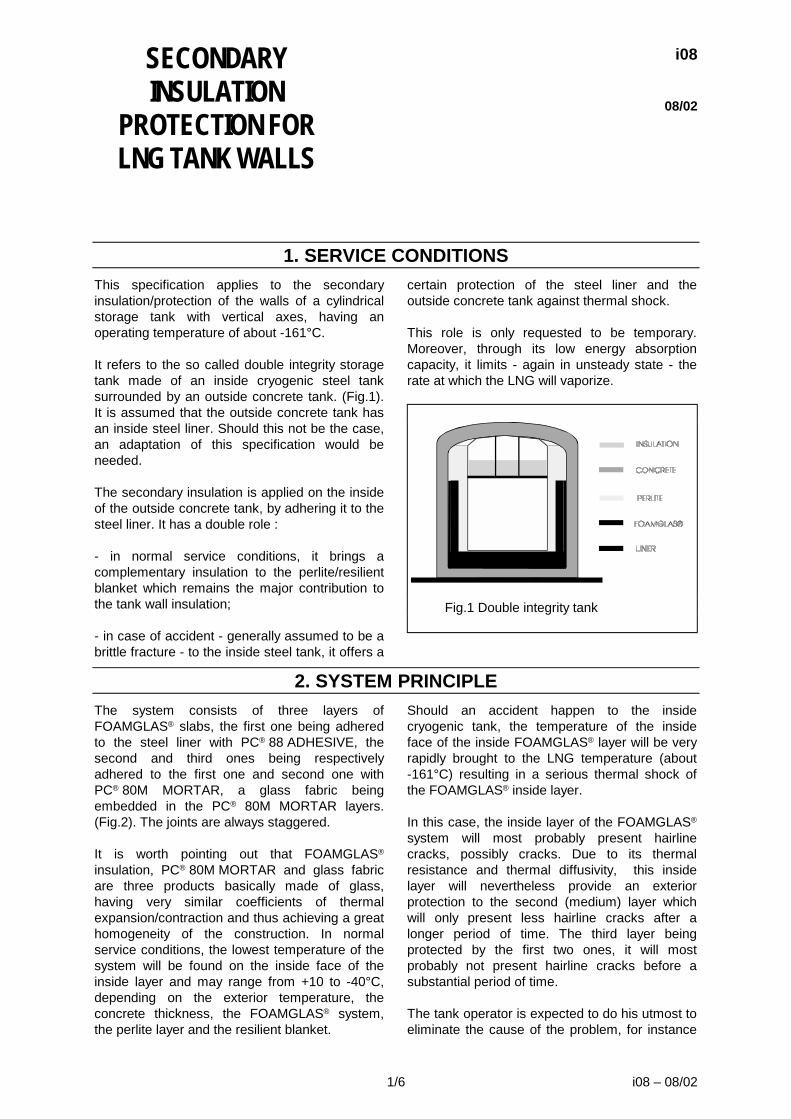
1/6 i08 – 08/02
i08
08/02
1. SERVICE CONDITIONSThis specification applies to the secondary insulation/protection of the walls of a cylindrical storage tank with vertical axes, having an operating temperature of about -161°C. It refers to the so called double integrity storage tank made of an inside cryogenic steel tank surrounded by an outside concrete tank. (Fig.1). It is assumed that the outside concrete tank has an inside steel liner. Should this not be the case, an adaptation of this specification would be needed. The secondary insulation is applied on the inside of the outside concrete tank, by adhering it to the steel liner. It has a double role : - in normal service conditions, it brings a complementary insulation to the perlite/resilient blanket which remains the major contribution to the tank wall insulation; - in case of accident - generally assumed to be a brittle fracture - to the inside steel tank, it offers a
certain protection of the steel liner and the outside concrete tank against thermal shock. This role is only requested to be temporary. Moreover, through its low energy absorption capacity, it limits - again in unsteady state - the rate at which the LNG will vaporize.
Fig.1 Double integrity tank
2. SYSTEM PRINCIPLEThe system consists of three layers of FOAMGLAS® slabs, the first one being adhered to the steel liner with PC® 88 ADHESIVE, the second and third ones being respectively adhered to the first one and second one with PC® 80M MORTAR, a glass fabric being embedded in the PC® 80M MORTAR layers. (Fig.2). The joints are always staggered. It is worth pointing out that FOAMGLAS® insulation, PC® 80M MORTAR and glass fabric are three products basically made of glass, having very similar coefficients of thermal expansion/contraction and thus achieving a great homogeneity of the construction. In normal service conditions, the lowest temperature of the system will be found on the inside face of the inside layer and may range from +10 to -40°C, depending on the exterior temperature, the concrete thickness, the FOAMGLAS® system, the perlite layer and the resilient blanket.
Should an accident happen to the inside cryogenic tank, the temperature of the inside face of the inside FOAMGLAS® layer will be very rapidly brought to the LNG temperature (about -161°C) resulting in a serious thermal shock of the FOAMGLAS® inside layer. In this case, the inside layer of the FOAMGLAS® system will most probably present hairline cracks, possibly cracks. Due to its thermal resistance and thermal diffusivity, this inside layer will nevertheless provide an exterior protection to the second (medium) layer which will only present less hairline cracks after a longer period of time. The third layer being protected by the first two ones, it will most probably not present hairline cracks before a substantial period of time. The tank operator is expected to do his utmost to eliminate the cause of the problem, for instance
SECONDARY INSULATION
PROTECTION FOR LNG TANK WALLS

2/6 i08 – 08/02
by pumping out the LNG (and possibly the perlite) before the end of this period of time. The great contribution of the PC® 80M MORTAR reinforced by glass fabric is to keep the slabs in place, in spite of the expected cracks. This principle has been used to a large extent with FOAMGLAS® cellular glass for high temperature applications, mainly for pipe
insulation. Its application in cryogenic conditions has been evaluated by several large scale tests, run by Pittsburgh Corning in its own laboratory and in independent laboratories. Reports are available on request. Due to the innovative nature of this application and the various requirements that the design engineer may want to achieve, this specification can only be general by nature and Pittsburgh Corning cannot be held responsible for it.
8
6
7
2
34
1 5
LNGTANK
1. Complementary local protection 2. PC® 88 ADHESIVE 3. PITTSEAL® 444N 4. PC® 80M MORTAR + glass fabric 5. Perlite concrete 6. Steel liner 7. Loose perlite 8. FOAMGLAS® insulation Fig.2 Laminated system in three layers
3. PRELIMINARY CONDITIONS3.1. FOAMGLAS® slabs and pieces should be transported and stored vertically. Handle the packages with care. FOAMGLAS® insulation packages should be protected from the elements whilst in storage and not allowed to come into direct contact with the ground. 3.2. The surface to be insulated should be clean and free from all traces of grease, rust, dust and any foreign matter. The design engineer should decide whether a coat of anticorrosion paint is
necessary, and this paint being compatible with the service temperature and the adhesive (if any). If he decides to specify one, the following rules should be observed : 3.2.1. The surface, if corroded or otherwise unsuitable, should be sandblasted before the possible anticorrosion coat is applied. (SS-Sa-2 1/2)

3/6 i08 – 08/02
3.2.2. Any surface imperfection should be wire brushed and then coated with a new layer of anticorrosion paint. The surface should be perfectly dry before applying the insulation. 3.2.3. When an adhesive is used, the compatibility between the anticorrosion paint and the adhesive should be verified before applying the insulation. N.B. It is worth noting that, in several previous cases of LNG tanks, no complementary anticorrosion paint had been used, the steel plates being supplied with a factory applied anticorrosion paint and welded in place.
3.3. The surface and the materials used should be dry before and during application, and should remain dry until start up. 3.4. The application of FOAMGLAS® insulation should be carried out at ambient temperature (No application when the equipment is in service). 3.5. The temperature limits of the accessory products should be respected during both storage and application. 3.6. Hydrostatic, radiographic and other tests should be completed before applying the insulation.
4. DETERMINATION OF REQUIRED INSULATION THICKNESS4.1. Heat transfers should be limited to acceptable values regarding both economic and functional aspects. (To provide enough insulation under normal service conditions.) 4.2. Enough protection should be provided to the steel liner in failure conditions. Since the FOAMGLAS® insulation is only a complementary insulation to the perlite/resilient blanket under normal service conditions, these products constituting the main part of the thermal resistance and providing cheaper thermal resistance, the second criterion (thermal protection) is generally the dominant one for the FOAMGLAS® thickness selection.
In case of failure, the insulation provided by the perlite/resilient blanket is substantially reduced and rapidly becomes negligible. The FOAMGLAS® insulation needed to provide a certain protection to the steel liner (temperature not lower than what is acceptable for carbon steel i.e. about -25°C/-30°C) can be evaluated by testing. Mathematical models are only a guideline since they usually do not take into account some particular points of the construction and its evolution during the time of the "accident". From previous tests, carried out under similar conditions, it has been found that an outside layer of 100 mm (4"), a middle layer of 60 mm (2.5") and an inside layer of 60 mm (2.5") provide a thermal protection to the steel liner for more than 24 hours. (Reports are available on request).
5. USED MATERIALS5.1. Insulation Material The insulation should be FOAMGLAS® (See data sheets A02 to A03). If necessary (generally it is not the case due to the diameter of the tank) the slabs should be adjusted by abrasion to fit the curvature of the tank, or radiused and bevelled lags of the appropriate shape should be used. 5.2. Anticorrosion layer The anti-corrosion layer should not be based on bitumen, tar, silicone or polyurethane. Zinc chromates or similar coatings are generally compatible with PC® 88 ADHESIVE. The compatibility between the anticorrosion paint and the adhesive should be verified before the insulation is applied. Examples of paints compatible with PC® 88 ADHESIVE: - READLEAD EPOXY PRIMER (GOODGLASS WALL & Co.) - STRATHCLYDE PA 10 RED OXIDE PRIMER - COLTURIET SEALER (SIGMA COATINGS).
5.3. Adhesive 5.3.1. Exterior layer The exterior layer shall be applied directly onto the steel liner with PC® 88 ADHESIVE, a two-component adhesive based on bitumen modified with polyurethane. Its service temperature ranges from -40/-55°C to +80°C. But the temperature of the PC® 88 ADHESIVE should be maintained between +20°C and +35°C before and during application. The temperature of the metal surface to be insulated should not be lower than +5°C during application. If rapid adhesion is required, as for the lower part of a tank for example, the temperature of the surface to be insulated should be maintained between +20°C and +35°C.

4/6 i08 – 08/02
5.3.2. Middle and inside layer The adhesive to be used shall be PC® 80M MORTAR, a two-component, inorganic adhesive, based on glass powder and silica dispersion. The temperature of the PC® 80M MORTAR should be maintained between +5 and +45°C before and during application. The temperature of the surface to be insulated should not be lower than +5°C during application.
5.4. Glass fabric reinforcement Acrylic resin stabilized glass fabric with following characteristics : - Surface weight 150 to 270 g./m² - Thickness 0.4 to 0.7 mm - Mesh 430 to 630 openings /dm² - Width about 100 cm Example of glass fabric : PC® FABRIC 79G 5.5. Joint sealant PITTSEAL® 444N, a one-component sealer based on polyisobutylene (See data sheet P41).
6. APPLICATION6.1. Application of the first layer 6.1.1. Differences from the geometrical, cylindrical form of the steel liner shall not generally exceed 10 mm for a distance of 2 meters. Local irregularities, due to welding for instance, may exceed this value provided they are adequately treated (See 6.1.3.). 6.1.2. The PC® 88 ADHESIVE should be prepared according to the manufacturer's instructions (technical information sheet P05). 6.1.3. The FOAMGLAS® slabs should be made to exactly fit the tank and each other, in order to avoid gaps. Steps or irregularities of the steel liner can be smoothed out by presenting the dry FOAMGLAS® element to the surface and shaping it locally by abrasion. An alternative method consists in placing a joint in front of a local irregularity (welding line, for instance). Should any slabs be broken during application, the resulting joints should be filled with PC® 88 ADHESIVE. 6.1.4. The adhesive should be applied with a 5 mm deep notched trowel all over the slab surface to be bonded as well as the two adjacent edges. To make the system as tight as possible, the joints should be completely filled. 6.1.5. FOAMGLAS® insulation should be applied in rows, starting at the bottom of the tank. The vertical joints of each insulation layer should be staggered. Joints should also be staggered between the various layers. 6.1.6. Each slab to be laid should be pressed firmly against the previous one, thus making the joints perfectly tight. Surplus adhesive exuding from the joints should be removed before it sets. 6.1.7. During the application of the first layer, and before the used adhesive has set, this first layer shall be gently scraped by using a FOAMGLAS® element, to make it as regular and geometrical
as possible and constitute an easy substrate for the application of the second layer. 6.2. Application of the second layer 6.2.1. The surface of the first layer shall be controlled as far as its geometry is concerned. Moreover, any dust or foreign matter will be eliminated, before the application of the second layer. 6.2.2. The PC® 80M MORTAR should be prepared according to the manufacturer's instructions, preferably using an automatic mixing equipment. 6.2.3. The FOAMGLAS® slabs should be made to fit exactly onto the first layer surface and to each other, in order to avoid gaps. 6.2.4. The PC® 80M MORTAR will be applied with a notched trowel (notches 5 x 5 x 5 mm) on the first layer. The glass fabric will be embedded in the fresh the PC® 80M MORTAR layer and trowelled smooth. Immediately, or after the PC® 80M MORTAR has set, PC® 80M MORTAR shall be applied with the same notched trowel on the slab surface and the two adjacent edges of the FOAMGLAS® slabs of the second layer which will then be firmly pressed onto the first layer and onto each other to make the joints as tight as possible. 6.2.5. FOAMGLAS® insulation should be applied in rows, starting at the bottom of the tank. The vertical joints of each insulation layer should be staggered. Joints should also be staggered between the various layers. 6.2.6. Surplus of PC® 80M MORTAR exuding from the joints should be removed before it sets. 6.2.7. After the application of the second layer, preferably every half workday, this second layer shall be gently scrapped by using a FOAMGLAS®

5/6 i08 – 08/02
element to make it as regular and geometrical as possible and constitute an easy substrate for the application of the third layer. 6.3. Application of the third layer 6.3.1. The surface of the second layer shall be controlled as far as its geometry is concerned. Moreover, any dust or foreign matter will be eliminated, before the application of the third layer. 6.3.2. The PC® 80M MORTAR should be prepared according to the manufacturer's instructions, preferably using an automatic mixing equipment. 6.3.3. The FOAMGLAS® slabs should be made to fit exactly onto the second layer and to each other, in order to avoid gaps. 6.3.4. The PC® 80M MORTAR will be applied with a notched trowel (notches 5 x 5 mm) on the second layer. The glass fabric will be embedded in the still fresh PC® 80M MORTAR layer and trowelled smooth. Immediately, or after the PC® 80M MORTAR has set, the PC® 80M MORTAR shall be applied with the same notched trowel on the slab surface and the two adjacent edges of the FOAMGLAS® slabs of the third layer which will then be firmly pressed onto the second layer and onto each other to make the joints as tight as possible. 6.3.5. The FOAMGLAS® insulation should be applied in rows, starting at the bottom of the tank. The vertical joints of each insulation layer should be staggered. Joints should also be staggered between the various layers. 6.4. Use of prefabricated modules It is possible to replace the second and the third layer of FOAMGLAS® by one layer of FOAMGLAS® modules, although this solution is only suggested for the current part of the wall and is not recommended for particular parts such as the wall/floor connection or in the vicinity of singular points. 6.4.1. Fabrication of FOAMGLAS® modules The modules are made of two FOAMGLAS® slabs adhered together with PC® 80M MORTAR, the adhesive layer being reinforced by a glass fabric having the previously outlined properties. Modules can be prepared in a fabricating shop and, after drying, applied with PC® 80M MORTAR onto the first layer of FOAMGLAS® slabs already in place, also using the glass fabric reinforcement in the adhesive layer.
6.4.1.1. The PC® 80M MORTAR should be prepared according to the manufacturer's instructions, preferably using an automatic mixing equipment. 6.4.1.2. A wooden calibre will be used to ensure that the FOAMGLAS® slabs can be adhered on top of each other without creating "steps" at the edges. 6.4.1.3. Apply the PC® 80M MORTAR with a notched trowel (notches 5 x 5 x 5 mm) on a FOAMGLAS® slab placed on a horizontal table. The glass fabric will be embedded in the fresh adhesive layer and trowelled smooth. Immediately, or after the reinforced adhesive has set, another full coat of PC® 80M MORTAR will be applied with the same notched trowel onto the whole surface of the second FOAMGLAS® slab, which will then be firmly pressed onto the already coated first one. 6.4.1.4. Enough drying time will be given to the system and then the edges will be trimmed to be free of any squeezed out adhesive. 6.4.1.5. The modules thus produced will be placed on a reusable transport device and will be carried from the fabricating shop to the scaffolding. 6.4.2. Installation of the modules 6.4.2.1. The surface of the already applied first layer shall be controlled as far as its geometry is concerned. Moreover, any dust or foreign matter will be eliminated before the application of the modules. 6.4.2.2. The PC® 80M MORTAR should be prepared according to the manufacturer's instruction, preferably using an automatic mixing equipment. 6.4.2.3. The FOAMGLAS® modules should be made to fit exactly onto the first layer surface and to each other, in order to avoid gaps and to make the joints as tight as possible. 6.4.2.4. The PC® 80M MORTAR will be applied with a notched trowel (notches 5 x 5 x 5 mm) on the first layer. The glass fabric will be embedded in the fresh PC® 80M MORTAR layer and trowelled smooth. Immediately, or after the PC® 80M MORTAR has set, the PC® 80M MORTAR shall be applied with the same notched trowel on the surface and the two adjacent edges of the FOAMGLAS® modules which will then be firmly pressed onto the first layer and on to each other to make the joints as tight as possible.
6.4.2.5. The FOAMGLAS® modules should be applied in rows, starting on a horizontal line about 3 metres higher than the wall/floor junction. Horizontal and vertical joints of the FOAMGLAS® modules layer should be staggered between themselves and in relation to the first layer. 6.5. Floor/wall/ring connection Only the three-system will be used for this part. Our suggestion is based on the following assumptions : No significant relative movement takes place between the concrete wall and the floor; the insulation is applied to the annulus after filling the possible annulus gaps to be found in the concrete floor after running the water tests. Depending on the possible movements between the FOAMGLAS® bottom insulation, the concrete ring under the shell of the tank and the floor slab, an expansion joint will be foreseen in the horizontal insulation of the cavity. It will preferably be a Z joint. Since the permanent PITTSEAL® 444N mastic does not resist cryogenic conditions so well as the laminated PC® 80M MORTAR system, another slab of laminated FOAMGLAS®/PC® 80M MORTAR will
be applied with PITTSEAL® 444N on the expansion joints. 6.6. Vertical wall finish It is recommended that no finish, of any kind, should be applied on the surface of the FOAMGLAS® slabs or modules. 6.7. Expansion joints Should any expansion joint be requested by the design engineer, it should be Z-shaped and filled with PITTSEAL® 444N. There, it is advisable to adhere a laminated slab with PC® 80M MORTAR to offer local complementary protection. Due to the stable nature of the concrete outer tank and its liner and to the moderate temperature variations under normal conditions, expansion joints are normally not required in the wall insulation/protection secondary system. 6.8. Flashing Flashing should be provided on the top of the secondary wall insulation system to protect it during the installation period and before the tank is commissioned. It is recommended to repair flashing immediately after any major failure.
Pittsburgh Corning GmbH (Austria)
Pittsburgh Corning Nederland B.V.
Pittsburgh Corning Schweiz A.G.
FOAMGLAS® Península Ibérica
Pittsburgh Corning Scandinavia ab.
Deutsche Pittsburgh Corning GmbH
Pittsburgh Corning UK Ltd.
Pittsburgh Corning Norway
Pittsburgh Corning Italy
Pittsburgh Corning France S.A.
The innovative insulation people
Pittsburgh Corning Europe is also represented in: Croatia, Czech Republic, Denmark, Greece, Hungary, Poland, Rumania, Russian Federation, Slovak Republic, Slovenia, Ukraine and Africa.

1/4 i10 – 08/02
i10
08/02
1. SERVICE CONDITIONS This specification applies to the insulation of piping and equipment installed in the open air with a service temperature from ambient to a
maximum of +220°C aboard offshore platforms or ships.
2. PRELIMINARY CONDITIONS2.1. FOAMGLAS® slabs and pieces should be transported and stored vertically. Handle the packages with care. FOAMGLAS® insulation packages should be protected from the elements whilst in storage and not allowed to come into direct contact with the ground. 2.2. The surface to be insulated should be clean and free from all traces of grease, rust, dust and any foreign matter. The design engineer should decide whether a coat of anticorrosion paint is necessary, and the type of paint compatible with the service temperature and the adhesive used (if any). If he decides to specify a paint, the following rules should be observed: 2.2.1. The surface, if corroded or otherwise unsuitable, should be sandblasted before the possible anticorrosion coat is applied (SS-Sa-2 1/2).
2.2.2. Any surface imperfection should be wire brushed and then coated with a new layer of anticorrosion paint. The surface should be perfectly dry before applying the insulation. 2.3. The surface and the materials to be used should be dry before and until the end of application. 2.4. The application of FOAMGLAS® insulation on pipes or equipment should be done at ambient temperature (no application when piping or equipment is in service). 2.5. The temperature limits of the accessory products should be respected during both storage and application. 2.6. Hydrostatic, radiographic and other tests should be completed before applying the insulation.
3. DETERMINATION OF INSULATION THICKNESS3.1. Heat losses should be limited to acceptable values with respect to both economic and functional aspects. 3.2. The surface temperature on the outer surface of the insulation should be kept under +60°C to prevent burns.
3.3. If service temperature is higher than +120°C or if pipes are heat traced, a double layer system is recommended.
4. MATERIALS TO BE USED4.1. Insulation material The insulation should be FOAMGLAS® cellular glass (see also data sheets A01 to A16) in preformed sections, radiused and bevelled lags or slabs. When ordering the insulation, service temperature should be indicated to allow the choice of a suitable adhesive for the fabrication of pipe sections or radiused and bevelled lags. The insulation of standard 90° or 45° - bends (R = 1.5 D) may be prefabricated at the factory,
as for the straight pipe sections. Non-standard bends, T-pieces, reducers and other equipment should be insulated with pieces cut to size on site. Flanges and valves should be insulated with pipe shells of larger dimensions adapted on site.
OFFSHORE PLATFORMS
AND SHIPS

2/4 i10 – 08/02
4.2. Anti-abrasive. LOW TEMPERATURE ANTI-ABRASIVE should be chosen for temperatures from ambient to +120°C and PC® HIGH TEMPERATURE ANTI-ABRASIVE for temperatures above +120°C (see data sheet P21). The anti-abrasive coating should be applied onto the inner side of the FOAMGLAS® elements that will be in contact with the metal pipe or equipment. Never apply the anti-abrasive on the pipe itself. The anti-abrasive can be sprayed at the factory or applied on site by brushing a thin layer onto the inside of the insulation. The anti-abrasive should be completely dry before the insulation material is applied. 4.3. Joint sealant Silicone mastic adapted to service temperature. 4.4. Adhesive For equipment operating up to +80°C or +120°C, an adhered system using PC® 88 ADHESIVE, a two-component adhesive based on bitumen modified with polyurethane, is possible (see data sheet P05). If low working stress is expected, PC® 88 ADHESIVE can be used up to +120°C, otherwise the maximum operating temperature is limited to +80°C. PC® 88 meets the requirements
of ASTM C692, and ASTM C871 regarding stress corrosion. 4.5. Insulation fixing straps The straps should be in AISI type 304 (BSI 304 216) stainless steel and should be 12.7 mm wide x 0.5 mm thick. Wire to fix FOAMGLAS® shells or segments should be avoided, due to the wire cutting of the FOAMGLAS® surface. 4.6. Finishes and claddings. 4.6.1. The metal cladding should be steel sheets, corrugated, flat or hammered. The easiest way to apply the jacket is to band it. Pop rivets or screws may also be used after having held the jacket tightly with temporary bands. A cushion layer of fibrous insulation between FOAMGLAS® insulation and the jacket should be avoided. This top layer will absorb ambient moisture during humid weather and could result in corroding the metal jacket. 4.6.2. Flexible mastic with fabric reinforcement should be sea-water and fire resistant, according to safety regulations.
5. APPLICATION5.1. Application of insulation We would not suggest oversized insulation because of vibrations on ships or platforms. 5.2. The insulation system requirements as well as the insulation thickness will depend on the service temperature of the pipe or equipment. 5.2.1. Service temperatures up to +120°C. A single layer system is sufficient for this temperature range. A double layer system should be applied when the recommended insulation thickness is bigger than the maximum available thickness or if pipes are heat traced. 5.2.1.1. Piping, elbows and fittings (Fig. 1) LOW TEMPERATURE ANTI-ABRASIVE should be applied onto the inner side of the FOAMGLAS® elements that will be in contact with the metal pipe or equipment. Never apply the anti-abrasive on the pipe itself. The anti-abrasive can be sprayed at the factory or applied on site by brushing a thin layer onto the inside of the insulation. The anti-abrasive should be completely dry before the insulation material is applied. Shells and segments appropriate to the shape of the surface to be insulated should be dry applied with staggered joints. All joints should be sealed with silicone mastic. After applying the shells or segments to the pipe or equipment, they will be held in place by means of 2 stainless steel straps per shell or segment. Care must be taken to
ensure that the FOAMGLAS® cellular glass units are not broken when tightening the fixing straps. Any damaged piece should be replaced.
1 LOW TEMPERATURE ANTI-ABRASIVE 2 FOAMGLAS® cellular glass 3 Silicone mastic 4 Stainless steel straps 5 Mastic coating 6 Metal jacket
Fig. 1 Single layer system for service temperatures up to +120°C

3/4 i10 – 08/02
5.2.1.2. Vessels (Fig. 2). Segments appropriate to the shape of the surface to be insulated should be applied with staggered joints. Staggering the segments is not needed for vessel heads or other irregular forms. Segments will be adhered and joints filled with
PC® 88 ADHESIVE. Temporary banding is needed to give PC® 88 ADHESIVE time to set. Excess of adhesive running out of the joints should be removed before it sets. Extra steel straps are not needed when using PC® 88 ADHESIVE.
12 3
4
1 Horizontal vessel with domed ends.2 FOAMGLAS® vessel segments adhered with PC® 88 ADHESIVE.
3 PC® 88 ADHESIVE in the joints.4 Manhole insulated with same insulation.
thickness as vessel.
5
5 Surface protection
Fig.2 Vessel insulation. Single layer system for service temperatures up to +120°C. FOAMGLAS® segments adhered and joints sealed with PC® 88 ADHESIVE.
5.2.2. Service temperatures up to +220°C A double layer system is generally sufficient for this temperature range. 5.2.2.1. Piping, elbows and fitting (Fig. 3). Before applying of the FOAMGLAS® shells, the internal surface of the shells in contact with the pipes should be coated with a thin layer of PC® HIGH TEMPERATURE ANTI-ABRASIVE, preferably factory applied. Shells and segments appropriate to the shape of the surface to be insulated should be dry applied with staggered joints regarding each other and to the second layer. The first layer of FOAMGLAS® shells will be held in place with glass fibre reinforced tape. The outer layer is dry applied over the first one, with silicone mastic in the joints, and fixed by means of 2 stainless steel straps per shell or segment. Care must be taken to ensure that the FOAMGLAS® cellular glass units are not broken when tightening the fixing straps. Any damaged piece should be replaced.
1 2 3 4 5 6 7 1 PC® HIGH TEMPERATURE ANTI-ABRASIVE 2 FOAMGLAS® cellular glass 3 Glass fibre reinforced tape 4 Silicone mastic 5 Stainless steel straps 6 Mastic coating 7 Metal jacket Fig.3 Double layer systems for service temperatures up to +220°C

5.2.2.2. Vessels Before application of the FOAMGLAS® segments, the internal surface of the segments in contact with the vessels should be coated with a thin layer of PC® HIGH TEMPERATURE ANTI-ABRASIVE, preferably factory applied. Segments appropriate to the shape of the surface to be insulated should be dry applied with staggered joints regarding each other and to the second layer. The first layer of FOAMGLAS® segments will be held in place with metal straps. Staggering the segments is not needed for vessel heads or other irregular forms.
The outer layer will be adhered and joints filled with PC® 88 ADHESIVE. Temporary banding is needed to give PC® 88 ADHESIVE time to set. Excess of adhesive running out of the joints should be removed before it sets. Extra steel straps are not needed when using PC® 88 ADHESIVE. 5.2.2.3 Vessel dome roof. A metal jacketing applied over a cell filler or a bitumen adhered membrane should be applied on top of a vessel doomed roof. Proper maintenance of the membrane should be foreseen.
6. SURFACE PROTECTION6.1. Mastic coating The external surface of FOAMGLAS® must be coated with an adequate mastic coating. This mastic should be sea-water and fire resistant according to safety regulations. It must be applied before metal cladding but it should not replace the metal cladding. 6.2. Metal cladding In order to try and prevent the system from being mechanically damaged, It is usually necessary to
apply a metal cladding. This metal cladding must be held in place by means of stainless steel straps or other approved systems. 6.3. Flashing Appropriate techniques and materials should be used to make the areas around nozzles, manholes and other protrusions watertight; this also applies to junctions of horizontal and vertical surfaces.
We guarantee the physical properties of FOAMGLAS® cellular glass. Whilst great care is taken in formulating specifications, we cannot be held responsible for them due to imponderables on each specific jobsite.
Pittsburgh Corning GmbH (Austria)
Pittsburgh Corning Nederland B.V.
Pittsburgh Corning Schweiz A.G.
FOAMGLAS® Península Ibérica
Pittsburgh Corning Scandinavia ab.
Deutsche Pittsburgh Corning GmbH
Pittsburgh Corning UK Ltd.
Pittsburgh Corning Norway
Pittsburgh Corning Italy
Pittsburgh Corning France S.A.
The innovative insulation people
Pittsburgh Corning Europe is also represented in: Croatia, Czech Republic, Denmark, Greece, Hungary, Poland, Rumania, Russian Federation, Slovak Republic, Slovenia, Ukraine and Africa.

i21-08/02 1/4
i21
08/02
1. SERVICE CONDITIONS This specification applies to the insulation of chimneys having an inner acid resistant brick
lining with a service temperature of the flue gases up to 400°C.
2. PRELIMINARY CONDITIONS2.1. FOAMGLAS® slabs and pieces should be transported and stored vertically. Manipulate the packages with care. FOAMGLAS® insulation packages should be protected from weather influences whilst in storage and not allowed to come into direct contact with the ground.
2.2. The materials used should be dry before and until the end of the installation. 2.3. The temperature limits of the accessory products should be respected during both storage and application.
3. DETERMINATION OF REQUIRED INSULATION THICKNESSThe chimney designer will calculate heat losses and temperature gradients in winter and summer conditions for all possible flue gas temperatures and flow rates (gas velocity). Main criteria are as follows: 3.1. Temperature drop of flue gases between entrance and outlet in order to avoid condensation of acid gases (e.g. H2SO4) as well as water vapour after a "flue-gas washer" within the lining. Lowering of flue gas temperature will also reduce flow speed (flue gas becomes heavier because volume decreases when cooling down).
3.2. Structural outer shell of chimney must be protected from temperature in order to minimise the thermal stresses introduced into outer concrete wall even if ventilation on air space is inhibited. 3.3. Little temperature drop through the refractory brick masonry of the inner brick lining limiting thermal stresses. 3.4. Limit the heat transfer to the accessible ventilated air space to keep the temperature in the cavity at such a level, compared with the ambient temperature, that inspection, maintenance and minor repair works (e.g. for aircraft warning lights) can be carried out.
4. CONSTRUCTION TECHNIQUESEach company has its own design and construction procedures. Chimney construction being a very specialised field, we outline below just the rough principles. The generally used construction method will be the following (Fig.1 and Fig.2) : FOAMGLAS® applied to the outside of the inner flue gas lining constructed in acid resistant bricks: This provides an excellent insulation for the outer concrete chimney and allows an accessible air
space between insulation and concrete wall, thus greatly facilitating inspection. The FOAMGLAS® insulation is installed using HOECHST cement in the joints of the slabs around the external surface of the inner flue gas lining. Due to the differential thermal expansion and movement of the brick lining and the FOAMGLAS® insulation, an air space of approximately 8-10 mm should be kept between both layers.
INDUSTRIAL CHIMNEYS

2/4 i21-08/02
5. MATERIALS USEDThe materials listed below are appropriate for this specification. 5.1. Insulation material The insulation should be FOAMGLAS® cellular glass (see also Physical Properties sheet) in radiused and bevelled segments or flat slabs depending on the flue liner diameter to be insulated. Flat FOAMGLAS® slabs have following dimensions: 300 x 450 mm or 450 x 600 mm. Mainly the first dimensions are ordered. The slabs are applied vertically. Rigged pieces in L-shape can be ordered to cover insulation supports. To enable the manufacturer to chose the right adhesive when assembling prefabricated pieces, always specify application area or temperature to which insulation is exposed. 5.2. Mortar FOAMGLAS® masonry will be made with HOECHST Acid-Proof Cement HB or HOECHST Acid-Proof Cement HFR depending on product used for refractory bricks. Cement will be mixed with Potassium Silicate 42.5 Bé. Recommended mix ratio : HOECHST HB 3 kg + Potassium Silicate 42.5 Bé 1 kg HOECHST HFR 3 kg + Potassium Silicate 42.5 Bé 1 kg + water 0.25 kg. 5.3. Distancer Corrugated cardboard is the mainly used material to create a small air space between refractory bricks flow pipe and FOAMGLAS® insulation. During heat up, this cardboard will be burned away. 5.4. Insulation hoop fixing An alkali resistant glass fabric strip of medium weight (150 g/m²) and 3 mm mesh, 100 mm wide, is hooping each row of insulation slabs.
This strip is held in place by adhesive or with metal straps. 5.4.1. Adhesive for strips PC® 74A2 is a one component product of hydraulic setting. 5.4.2. Metal straps Annealed stainless steel (AISI type 304; BSI 304 S 16) should measure 13 mm wide by 0.4 mm thick. The following table has been developed in order to limit the theoretical gap (b) to approximately 4 mm
WIDTH OF FLAT FOAMGLAS® SLAB
MINIMUM DIAMETER OF
FLOW GAS PIPE
150 mm 1.50 m 225 mm 3.00 m 300 mm 5.00 m 450 mm 12.50 m
a
b
R R'
b R' - RR' = R² + a²
Fig.3

3/4 i21 – 08/02
6. APPLICATIONShape of FOAMGLAS® segments or size of FOAMGLAS® slabs must match the curvature of the inner flow gas pipe with a maximum gap of 4mm. Slabs can be cut vertically on site during unpacking, in order to reduce the gap between pipe and insulation plates. Cutting can be carried out easily by using a normal saw. (Fig.3) 6.1. Bricks of inner flue gas lining are first bricked up slightly higher than a row of FOAMGLAS® slabs and a corrugated cardboard liner is placed around them. This liner should avoid any contact between internal refractory bricks and insulation. 6.2. FOAMGLAS® slabs are installed with HOECHST Acid-Proof Cement HB or HFR mixed with potassium silicate (see 5.2.). This mortar should fill correctly all joints. 6.3. After having completed the circle, a glass fabric strip (100 mm wide) is applied on the external surface of insulation. This glass fabric can be adhered or fixed with metal straps. 6.3.1. Adhered glass fabric strip is laid on PC® 74A2 gobs applied at 1 m intervals on the FOAMGLAS® surface as well as on the 200 mm overlap of the strip itself. 6.3.2. Metal straps holding the glass fabric strip must be tensioned very carefully and seals must be closed with an appropriate sealer-pincer. This type of glass fabric fixing is used where dilation movements of the insulation are limited or reduced by dilation joints. 6.4. Insulation may be supported by wedge shaped refractory bricks at 2 to 3 m distance. This support ring will be insulated by L-shaped slabs or by a second insulation layer attached by studs or clamps. This layer will also be secured
by a glass fabric hoop fixed as indicated in paragraph 6.3. 6.5. A weather protection could be given to the FOAMGLAS® insulation at the 10 m area situated at vent holes level on top of the chimney by a glass fabric reinforced PC® 74A2 coating or by an adequate protection foil held in place by stainless steel bands.
10
6
78
9
4 11
3
2
5
1
1 Outside wall of stack. 2 Concrete ring. 3 Air gap 4 Aeration stream. 5 Access walk. 6 Acid resistant brick lining. 7 Distance layer, about 10 mm (cardboard). 8 FOAMGLAS® insulation. 9 Glass fabric strips. 10 Packing cord. 11 Flue gases. Fig.1

1
2
3
4
5
6
7
8
9
1 Outside wall of stack 2 Glass fabric strip 3 FOAMGLAS® insulation 4 Sheet lead 5 Packing cord 6 Supporting ring 7 Acid resistant brick lining 8 Ventilated space 9 Distance layer Fig.2
Whilst great care is taken in formulating specifications, we cannot be held responsible for them due to imponderables of each specific jobsite.
Pittsburgh Corning GmbH (Austria)
Pittsburgh Corning Nederland B.V.
Pittsburgh Corning Schweiz A.G.
FOAMGLAS® Península Ibérica
Pittsburgh Corning Scandinavia ab.
Deutsche Pittsburgh Corning GmbH
Pittsburgh Corning UK Ltd.
Pittsburgh Corning Norway
Pittsburgh Corning Italy
Pittsburgh Corning France S.A.
The innovative insulation people
Pittsburgh Corning Europe is also represented in: Croatia, Czech Republic, Denmark, Greece, Hungary, Poland, Rumania, Russian Federation, Slovak Republic, Slovenia, Ukraine and Africa.

1/4 i22 – 08/02
i22
08/02
1. SERVICE CONDITIONS This document applies to the insulation of liquefied gas tank bases.
2. GENERAL INFORMATIONFOAMGLAS® HLB cellular glass is particularly recommended for this application owing to its high compressive strength, non absorptive and non combustible nature. A very large number of existing tank bases have been built using one of the various grades of FOAMGLAS® HLB insulation. Nevertheless, the information provided by Pittsburgh Corning in this document is not meant to replace specifications which are prepared by design engineers. The actual design of a load bearing insulated base is a specialised engineering discipline and numerous qualified companies have their own preferred design and construction procedures. When designing a FOAMGLAS® HLB insulation for a load bearing insulated tank base system, many factors are normally to be evaluated in determining the specific type of FOAMGLAS® HLB insulation and capping system to be employed.
These include, but are not limited to : tank height, type of liquid to be stored, storage temperature, preferred application procedures, local environmental conditions such as earthquake requirements, load during hydro testing, existence of non vertical forces, etc. These factors, along with the need to satisfy certain design safety factor requirements, will generally determine the most appropriate type of HLB material. Historically, many load bearing applications of FOAMGLAS® cellular glass, and especially tank bases, have been designed with a safety factor of three (3), based on the maximum working stress and the average compressive strength. It is the position of Pittsburgh Corning that the actual choice of safety factor is the responsibility of the design engineer in conjunction with the owner after a thorough consideration of the most severe prevailing or anticipated local design criteria.
3. WHY FOAMGLAS® HLB INSULATION ?Although Pittsburgh Corning produces other grades of cellular glass insulation, the HLB insulation grades are specifically manufactured to meet the needs of the tank base industry world-wide. Only FOAMGLAS® HLB insulation is recommended for such high load bearing applications. This series of products specifically provides reliable high compressive strength without sacrificing low thermal insulation
conductivity. In addition, FOAMGLAS® HLB insulation is the only material to our knowledge, providing the following unique combination of physical properties : - High insulation efficiency. - Impermeability to moisture and other liquids. - Dimensional stability under temperature extremes. - Non combustibility, it cannot burn. - Low coefficient of thermal expansion.
FOAMGLAS® HLB
FOR THE INSULATION OF LIQUEFIED GAS
TANK BASES

2/4 i22-08/02
4. EFFECTIVE COMPRESSIVE STRENGTH OF FOAMGLAS® HLB Data sheet A04 lists the compressive strength when tested according to ASTM C 240 or EN 826 standard and the thermal conductivity at ambient temperature. Both the ASTM C 240 and EN 826 standards include capping each face of the test specimen with hot bitumen and a roofing felt. They also specify several other test conditions. The compressive strength values published by Pittsburgh Corning only correspond to these test
methods. They can be modified (increased or decreased) by using different capping materials. The graph (see Fig.1) illustrates the behaviour of similar FOAMGLAS® slabs when tested with different cappings. Due to the normal dispersion of test results, somewhat different curves may be found when running a specific test. The form of the curves are also influenced by the type of equipment used (hydraulic or mechanical press).
STRESS
STRAIN %
1 2
3
4
00
1 ASTM C 240 or EN 826 2 Approved bituminous felt 3 Typical low organic or inorganic felt 4 Bare, no capping Fig.1 Capping Type
Note: The above is just to represent typical behaviour, should not be used for design purposes.

3/4 i22-08/02
5. GENERIC TYPES OF COMMONLY ENCOUNTERED TANK BASES
53421
8 10 7 6
1 Outer tank wall 2 Levelling screed 3 FOAMGLAS® HLB insulation 4 Concrete ring beam 5 Approved interleaving layer 6 Slip layer 7 Repartition slab 8 Inner tank bottom 9 Inner tank wall 10 Emergency complementary protection (Optionnal) Fig.2 Low tanks
The following are the most frequently encountered tank bases : Low Tanks : These tanks exert relatively low pressure on the base insulation. Generally the FOAMGLAS® HLB insulation is installed in multiple layers between two concrete layers. An appropriate grade of HLB insulation may also be employed under the ring wall bearing support in this case (see Fig.2). High Tanks : These require even higher compressive strength to support the inner tank contents. Tank wall loads would normally be supported by a perimeter ring made of lightweight insulation concrete, treated wood, or appropriate equal (see Fig.3). Liquefied Oxygen Tanks (LOX Tanks) : This type of tank is singled out for special attention because the interleaving material between FOAMGLAS® HLB layers and between other parts of the base system must be totally inorganic or have minimum organic content in order to ensure LOX compatibility, as specified by the design engineer. Acceptable interleaving (capping) materials have been identified. Contact the Pittsburgh Corning Technical Department for further information.
11 10 8
65
7
431 89
213
14
15
12
16
Fig.3 High Tanks
1 Concrete or metal base 2 Concrete or metal outside tank wall (optional) 3 Levelling screed 4 Lightweight concrete ring beam 5 FOAMGLAS® HLB tank base insulation 6 Approved interleaving material 7 Slip layer 8 Fine dry sand (optional) 9 Emergency complementary protection (optional) 10 Concrete slab 11 Tank bottom 12 Tank wall 13 FOAMGLAS® tank wall insulation system 14 Approved flexible adhesive to adhere and seal FOAMGLAS® slabs. 15 Optional finish. 16 Slip layer NOTE: The sketch only outlines the general principle of the connection between bottom and wall insulation. The design engineer should prepare in each case the appropriate drawing.

6. GENERAL PREPARATIONBefore applying the FOAMGLAS® HLB insulation, the following points should be noted : 6.1. FOAMGLAS® HLB insulation consists of pure glass and should therefore be handled with care to avoid damage to corners. The slabs are to be carried and stored in vertical position. Packages should be stored under cover and not in direct contact with the ground.
6.2. The existing standards for this type of construction work should be complied with. 6.3. The surface to be insulated and the materials to be employed should remain dry before, during and after application until work is completed. 6.4. The construction and especially the concrete part of it should be protected from freezing until completely dried out.
7. APPLICATION METHODThe following summaries are generally representative of the past practices frequently followed in many actual tank base applications : 7.1. Low Tanks for liquefied gas storage (Fig.2) A levelling layer of sand or concrete is poured on the base of the outer tank. In the case of concrete, the surface of this layer should be float finished but need not to be primed. Concrete should be given the longest curing time possible. 7.2. High Tank for liquefied gas storage (Fig.3) The construction method is basically the same as for Low Tanks, except for the following point: due to the high concentrated compressive loading on the periphery of the tank base supporting the inner tank wall, a ring beam of lightweight concrete, hardwood, or other suitable high strength insulation slabs may be used.
7.3. Liquid Oxygen Tanks The basic construction principles of this type of tank are the same as described earlier, with the important exception that all interleaving and capping materials used between, under and on top of the FOAMGLAS® HLB insulation layers should be totally inorganic or should have minimum organic content to provide the required compatibility with LOX. 7.3.1. Several alternative solutions are available to provide an inorganic interleaving material. These include the use of acceptable low organic content glass and/or ceramic fibre felts alone or in conjunction with an appropriate inorganic powder (PC® 85 POWDER or Hydrocal B11). It is important that adequate testing is carried out before approving any specific system and good field labour control is required to obtain an acceptable bearing surface for load transfer. Additional information on interleaving material for Liquid Oxygen Tank bottoms may be obtained from the Pittsburgh Corning Technical Department.
While great care is taken in formulating specifications, we cannot be held responsible for them do to imponderables of each specific jobsite.
Pittsburgh Corning GmbH (Austria)
Pittsburgh Corning Nederland B.V.
Pittsburgh Corning Schweiz A.G.
FOAMGLAS® Península Ibérica
Pittsburgh Corning Scandinavia ab.
Deutsche Pittsburgh Corning GmbH
Pittsburgh Corning UK Ltd.
Pittsburgh Corning Norway
Pittsburgh Corning Italy
Pittsburgh Corning France S.A.
The innovative insulation people
Pittsburgh Corning Europe is also represented in: Croatia, Czech Republic, Denmark, Greece, Hungary, Poland, Rumania, Russian Federation, Slovak Republic, Slovenia, Ukraine and Africa.

1/2 i23-09/03
i23
09/03
1. INTRODUCTION The present procedure is aimed at describing the installation method of FOAMGLAS® insulation for the corner protection of a LNG tank wall. It assumes that a cryogenic steel plate is installed on the cold side of the corner protection and goes under the tank to form a cup. It prevents that LNG comes into direct contact with the wall
of the tank in case of a leakage of the inside tank. In this design, the function of the FOAMGLAS® insulation consists in the limitation of the temperature variation of the concrete outside wall, should leakage of the inside tank occur.
2. PRELIMINARY CONDITIONS
2.1. FOAMGLAS® slabs and pieces should be transported and stored vertically. Handle the packages with care. FOAMGLAS® insulation packages should be protected from the elements whilst in storage and not allowed to come into direct contact with the ground. 2.2. The surface to be insulated should be clean and free from all traces of grease, rust, dust and any foreign matter.
2.3. The surface and the materials used should be dry before and until the end of the application, and should remain dry until start up. 2.4. The application of FOAMGLAS® insulation should be done at ambient temperature (no application when tank is in service). 2.5. The temperature limits of the accessory products should be respected during both storage and application.
3. MATERIAL USEDINSULATION MATERIAL The insulation shall be FOAMGLAS® cellular glass (see datasheet A 01 and A 02), type T4 (alternatively type S3 or HLB is acceptable). If necessary, the slab shall be adjusted by abrasion to fit the curvature of the wall.
ADHESIVE The adhesive shall be PC® 88, a two-component adhesive based on bitumen modified with polyurethane (see datasheet P 05).
INSTALLATION
PROCEDURE OF FOAMGLAS®
INSULATION FOR A LNG TANK CORNER
PROTECTION

Pittsburgh Corning GmbH (Austria)
Pittsburgh Corning Nederland B.V.
Pittsburgh Corning Schweiz A.G.
FOAMGLAS® Península Ibérica
Pittsburgh Corning Scandinavia ab.
Deutsche Pittsburgh Corning GmbH
Pittsburgh Corning UK Ltd.
Pittsburgh Corning Norway
Pittsburgh Corning Italy
Pittsburgh Corning France S.A.
The innovative insulation people
Pittsburgh Corning Europe is also represented in: Croatia, Czech Republic, Denmark, Greece, Hungary, Poland, Rumania, Russian Federation, Slovak Republic, Slovenia, Ukraine and Africa.
4. INSTALLATION PROCEDUREThe PC® 88 shall be prepared according to the manufacturer’s instruction (see datasheet P 05). It will be applied with 4 gobs near each corner of the FOAMGLAS® blocks which shall then be finally pressed on the tank wall. Before pressing the block onto the wall, the gobs shall have a diameter of about 10 cm and a thickness of about 1 cm. FOAMGLAS® blocks shall be laid in rows, starting at the bottom of the wall.
The joints between the slabs shall be dry and as tight as possible, by pressing finally each slab against the wall and the previous one. Steps or irregularities shall be matched, if needed shaping the slab by local abrasion. The second layer of FOAMGLAS® shall be adhered on the first one, using the same method. When using the gob technique, the coverage of PC® 88 ranges from 1.5 to 2 kg/m² per layer.
While great care is taken in formulating specifications, we cannot be held responsible for them due to imponderables of each specific jobsite.

I26-08/02 1/2
i26
08/02
1. SERVICE CONDITIONS This document applies to the base insulation of cylindrical storage tanks with vertical axes aimed at storing liquefied oxygen or nitrogen. This type of tank is singled out for special attention because the interleaving material between the FOAMGLAS® layers and the other parts of the base system must be totally inorganic or have a minimum organic content, in order to ensure LOX
compatibility, as specified by the design engineer. Acceptable interleaving (capping) materials have been identified. Before reading this document, it is recommended to read the i22 document which gives general information on FOAMGLAS® HLB cellular glass and tank base insulation.
2. PRELIMINARY CONDITIONS2.1. FOAMGLAS® slabs should be transported and stored vertically. Handle the packages with care. FOAMGLAS® insulation packages should be protected from the elements whilst in storage and not allowed to come into direct contact with the ground. 2.2. The surface to be insulated should be clean and free from all traces of grease, rust, dust and any foreign matter.
2.3. The surface and the materials used should be dry before and during application and should remain dry until start up. 2.4. The temperature limits of the accessory products should be respected during both storage and application.
3. DETERMINATION OF INSULATION THICKNESS3.1. Formation of condensation on the external surface of the bottom should be avoided. 3.2. Heat losses through the tank base should be limited to acceptable values with respect to
both economic and functional aspects (maximum evaporation rate). 3.3. Every precaution should be taken to avoid freezing of the ground.
4. MATERIALS USED4.1. Insulation material The insulation should be FOAMGLAS® cellular glass (See also physical properties sheet). To insulate tank bases, more specifically FOAMGLAS® HLB insulation, according to specification i22. 4.2. Surface cell filler The totally inorganic mineral based PC® 85 POWDER has been specially developed
to fill the open surface cells when FOAMGLAS® cellular glass is used as loadbearing insulation of tank bases. 4.3. Interleaving material Marglass 327 Loomstate fabric interleaving layer. This inorganic glass fibre felt is interleaved between FOAMGLAS® slabs as well as over and under the stack of slabs.
LIQUEFIED OXYGEN AND NITROGEN
TANK BASES

Pittsburgh Corning GmbH (Austria)
Pittsburgh Corning Nederland B.V.
Pittsburgh Corning Schweiz A.G.
FOAMGLAS® Península Ibérica
Pittsburgh Corning Scandinavia ab.
Deutsche Pittsburgh Corning GmbH
Pittsburgh Corning UK Ltd.
Pittsburgh Corning Norway
Pittsburgh Corning Italy
Pittsburgh Corning France S.A.
The innovative insulation people
Pittsburgh Corning Europe is also represented in: Croatia, Czech Republic, Denmark, Greece, Hungary, Poland, Rumania, Russian Federation, Slovak Republic, Slovenia, Ukraine and Africa.
5. APPLICATION OF BASE INSULATION5.1. Concrete slab A concrete foundation slab should be provided under the entire surface of the LOX tank base. A concrete ring beam should distribute the tank wall load. The central part should be supported by several layers of FOAMGLAS® insulation and a load distribution layer. 5.2. Irregularities in the surface of the outer tank steel plates laid on the concrete slab should never exceed 5 mm over a 2 meter distance. If this cannot be achieved, a concrete levelling screed should be applied. 5.3. After the levelling screed has completely dried out, a layer of PC® 85 POWDER should fill up the possible slight irregularities of the levelling screed. 5.4. Lay the Marglass 327 Loomstate fabric with butted joints. 5.5. Place the FOAMGLAS® slabs covered with PC® 85 POWDER on both sides. The PC® 85 POWDER application can be done in this way : spread PC® 85 POWDER on one face of the FOAMGLAS® slabs and level with a rubber scraper to fill all the open surface cells. Turn the powdered face gently downwards and install the FOAMGLAS® slab. (The powder stays adhered during handling). Spread the upper face of the FOAMGLAS® slab with PC® 85 POWDER and level. 5.6. Place the other layers of FOAMGLAS® coated with PC® 85 POWDER on both sides and lay a Marglass 327 Loomstate fabric between each layer. Joints of the various layers of FOAMGLAS® should be staggered. The last FOAMGLAS® layer will also be covered with
PC® 85 POWDER on its top and finished with Marglass 327 Loomstate fabric. 5.7. To create the load distribution layer, spread a layer of fine dry sand onto the last Marglass 327 Loomstate fabric. This sand layer can be replaced by a concrete slab, while making sure that two sheets of copper or aluminium (Thickness : 0.2 mm) are placed between the felt and the concrete, in order to prevent the concrete moisture from penetrating the bottom layers, and to obtain a slip layer. Note : 1. If the outer steel tank is replaced by an outer concrete tank, the inside, and especially the base, must be foreseen with a steel liner in order to create a water and water vapour barrier because the open joints of the FOAMGLAS® insulation, filled with inorganic material, do not present a good water and water vapour resistance compared to the classical built-up with bituminous interleaving materials. 2. Pittsburgh Corning has run substantial tests on the Marglass 327 Loomstate fabric/ FOAMGLAS® HLB insulation system, which were aimed at simulating water tests and service conditions. Test reports are available on request. 3. Marglass 327 Loomstate fabric is manufactured and supplied by :
Spunglass (Overseas) Ltd; Marglass Division Sherborne, Dorset England DT9 3RB Fax : (0) 935 81 62 84 Tel : (0) 935 81 37 22

I28-20-08/02 1/2
i28-20
08/02
1. SERVICE CONDITIONSThis document applies to the base insulation of cylindrical storage tanks with vertical axes aimed at storing hot liquids having temperatures up to
+150°C. For temperatures above +150°C, consult specification i28-30.
2. GENERAL INFORMATIONThe compressive strength of FOAMGLAS® cellular glass applied with hot bitumen or PC® 86T bitumen emulsion and capped with oil mixed sand is lower than the published compressive strength measured under ASTM/EN conditions. The reduction factor is about two in the test conditions set up following this specification (report available on request). The design engineer should decide on the safety factor to be used after having
taken into consideration the reduction factor. Generally a safety factor of 3 is used. Taking into account the reduction factor of 2, the safety factor would become 6. For tanks up to 15 m height and provided that the density of product in the tank is below hydrostatic load, FOAMGLAS® S3 can be used. For higher stress levels, contact the Technical Service of Pittsburgh Corning.
3. PRELIMINARY CONDITIONS3.1. FOAMGLAS® slabs and pieces should be transported and stored vertically. Handle the packages with care. FOAMGLAS® insulation packages should be protected from the elements whilst in storage and not allowed to come into direct contact with the ground. 3.2. The surface to be insulated should be clean and free from all traces of grease, rust, dust and any foreign matter.
3.3. The surface and the materials to be used should be dry before and during application, and should remain dry until start up. 3.4. The temperature limits of the accessory products should be respected during both storage and application.
4. DETERMINATION OF INSULATION THICKNESSHeat transfers should be limited to acceptable values with respect to both economic and functional aspects. (5 to 10 cm is a common thickness for
temperatures up to 80°C and 10 to 20 cm is a common thickness for temperatures up to 150°C)
5. MATERIALS TO BE USED5.1. Insulation material. The insulation should be FOAMGLAS® cellular glass (See also physical properties sheet). 5.2. Bedding material. 5.2.1. For temperatures up to 80°C. Hot oxidized bitumen 85/25, 110/30 or PC 86T will be used as bedding compound and sealant for FOAMGLAS® slabs. 5.2.2. For temperatures up to 150°C. One or two FOAMGLAS® cellular glass layers will be specified according to the selected total thickness.
The first interleaving layer between the concrete foundation slab and the FOAMGLAS® cellular glass layer will be PC® 86T Bitumen Emulsion. The same will be used for the interleaving layer between the first FOAMGLAS® cellular glass layer and the second one, if there is a second. 5.3. Load distribution layer. This top layer consists of oil mixed sand which can be a jobsite-made product consisting of washed and dried M34 sand (salt free) well mixed with approximately 75 l/m³ mineral lubrication oil without additives, such as Shell Vitrea 100 (no used oil because of corrosion danger).
HOT TANK BASE
Up to 150°C

Pittsburgh Corning GmbH (Austria)
Pittsburgh Corning Nederland B.V.
Pittsburgh Corning Schweiz A.G.
FOAMGLAS® Península Ibérica
Pittsburgh Corning Scandinavia ab.
Deutsche Pittsburgh Corning GmbH
Pittsburgh Corning UK Ltd.
Pittsburgh Corning Norway
Pittsburgh Corning Italy
Pittsburgh Corning France S.A.
The innovative insulation people
Pittsburgh Corning Europe is also represented in: Croatia, Czech Republic, Denmark, Greece, Hungary, Poland, Rumania, Russian Federation, Slovak Republic, Slovenia, Ukraine and Africa.
6. APPLICATION6.1. Concrete slab. A concrete foundation slab should be provided under the whole surface of the tank base. For tanks having a compressive strength under the tank wall section exceeding 0.1 N/mm², a concrete ring beam should bear the tank wall load. The central part should be supported by FOAMGLAS® S3 insulation covered with a load distribution layer (see 5.3.). 6.2. Surface irregularities of the concrete slab should never exceed 5 mm over a 2 metre distance. If this degree of precision cannot be achieved, a concrete levelling screed should be applied. 6.3. Application of insulation. 6.3.1. For temperatures up to 80°C. With hot oxidised bitumen type 85/25 or 110/30: On top of the previously primed dry substrate, slabs of FOAMGLAS® are laid in hot bitumen in parallel courses, with staggered joints. The hot bitumen is poured onto the substrate in sufficient quantity and at the right temperature. The slabs are to be pressed down and pushed in a diagonal direction so that the bitumen is squeezed up into the joints until it shows on top so that the joints are well butted together and fully adhered. Total coverage about 4.5 kg/m². With PC® 86T Bitumen emulsion: After the concrete surface has completely dried out, a layer of PC® 86T is applied on the concrete surface, while simultaneously pressing the FOAMGLAS® S3 slabs into the fresh mastic. Coat the edges of the already applied adjacent blocks with PC® 86T in order to fill the joints completely. Total coverage about 5 kg/m². 6.3.2. For temperatures up to 150°C. The system is similar to the one for tanks operating at a temperature lower than 80°C, except that the use of hot oxidised bitumen is not recommended for the first interleaving layer. 6.4. Create the load distribution layer by spreading a layer having a minimum thickness of 4 cm, of fine oil mixed sand onto the FOAMGLAS® insulation layer. If no ring beam has been made, a special device must be installed to prevent the load distribution layer from flowing. 6.5. Protect the top surface from weather and water ingress. Note: 1. When and after applying the oil mixed sand, no naked flame or welding can be used in the vicinity.
2. Since the sand granulometry may have an influence on the FOAMGLAS® S3 compressive strength, we indicate here the granulometry of dry M34 sand.
Mesh size Sieving retainings 100 µ m 99.5% 160 µ m 60.5% 200 µ m 11.5% 315 µ m 0.5 %
34 2 1
6
5
12347
5
6
1. Concrete 2. For service temperatures up to 80°C: Hot oxidised bitumen 85/25, 110/30 or PC® 86T For service temperatures up to 150°C: PC® 86T bitumen based product Or hot oxidised bitumen type 85/25 or 110/30
except for the bottom interleaving layer. 3. FOAMGLAS® insulation 4. Oil-sand mix (Dried M34 sand + lubrication oil - mineral without additives) 5. FOAMGLAS® T4 wall insulation 6. Cladding 7. Annular L-steel
Fig.1 Hot tank base up to 150°C

1/2 i28-30 – 08/02
i28-30
08/02
1. SERVICE CONDITIONS This document applies to the base insulation of cylindrical storage tanks with vertical axes
aimed at storing hot liquids having temperatures up to 250°C.
2. GENERAL INFORMATION The compressive strength of FOAMGLAS® cellular glass applied PC® 86T bitumen emulsion and capped with sand is lower than the published compressive strength measured under ASTM/EN conditions. Interleaving (capping) materials should be applied between the FOAMGLAS® layers. They should be acceptable from a compressive strength and a safety stand-point. The reduction factor is about two in the test conditions set up following this specification (report available on request).
The design engineer should decide on the safety factor to be used after having taken into consideration the reduction factor. Generally a safety factor of 3 is used. Taking into account the reduction factor of 2, the safety factor would become 6. For tanks up to 15 m height and provided that the density of product in the tank is below hydrostatic load, FOAMGLAS® S3 can be used. For higher stress levels, contact the Technical Service of Pittsburgh Corning.
3. PRELIMINARY CONDITIONS 3.1. FOAMGLAS® slabs and pieces should be transported and stored vertically. Handle the packages with care. FOAMGLAS® insulation packages should be protected from the elements whilst in storage and not allowed to come into direct contact with the ground. 3.2. The surface to be insulated should be clean and free from all traces of grease, rust, dust and any foreign matter.
3.3. The surface and the materials to be used should be dry before and during application and should remain dry until start up. 3.4. The temperature limits of the accessory products should be respected during both storage and application.
4. DETERMINATION OF INSULATION THICKNESS When calculating the thickness, heat losses through the tank base should be limited to
acceptable values with respect to both economic and functional aspects.
5. MATERIALS TO BE USED 5.1. Insulation material. The insulation should be FOAMGLAS® cellular glass (See also physical properties sheet). 5.2. Surface-cell filler. The totally inorganic mineral based PC® 85 POWDER has been specially developed to fill the open surface cells, when FOAMGLAS® cellular glass is used as loadbearing insulation of tank bases. 5.3. Interleaving material. CS Interglass 92200 Loomstate fabric interleaving layer. This inorganic glass fibre felt is interleaved between FOAMGLAS® slabs as well as below as on top of the stack.
5.4. Bedding material in case of a multiple layer application. PC® 86T bitumen emulsion should be used as bedding compound and sealant for FOAMGLAS® slabs to apply the first layer directly to the concrete (If its temperature does not exceed 80°C). 5.5. Load distribution layer. This top layer consists of fine dry sand. We indicate here the granulometrie of dry M34 sand.
Mesh size Sieving retainings 100 µ m 99.5% 160 µ m 60.5% 200 µ m 11.5% 315 µ m 0.5 %
HOT TANK BASE
Up to 250°C

Pittsburgh Corning GmbH (Austria)
Pittsburgh Corning Nederland B.V.
Pittsburgh Corning Schweiz A.G.
FOAMGLAS® Península Ibérica
Pittsburgh Corning Scandinavia ab.
Deutsche Pittsburgh Corning GmbH
Pittsburgh Corning UK Ltd.
Pittsburgh Corning Norway
Pittsburgh Corning Italy
Pittsburgh Corning France S.A.
The innovative insulation people
Pittsburgh Corning Europe is also represented in: Croatia, Czech Republic, Denmark, Greece, Hungary, Poland, Rumania, Russian Federation, Slovak Republic, Slovenia, Ukraine and Africa.
6. APPLICATION 6.1. Concrete slab. A concrete foundation slab should be provided under the entire surface of the tank base. For tanks having a compressive strength under the tank wall section exceeding 0.1 N/mm², a concrete ring beam should distribute the tank wall load. The central part should be supported by one or several layers of FOAMGLAS® insulation and a load distribution layer. 6.2. Surface irregularities of the concrete slab should never exceed 5 mm over a 2 metre distance. If this degree of precision cannot be achieved, a concrete levelling screed should be applied. In case of multiple layer system where the interface temperature between insulation and concrete does not exceed 80°C, the first FOAMGLAS® layer can be adhered directly onto the dried concrete surface with PC® 86T, a cold bitumen emulsion, by pressing the FOAMGLAS® slabs into a freshly applied mastic layer. Then, coat the edges of the already applied adjacent blocks with PC® 86T in order to fill the joints completely. Total coverage about 5 kg/m². 6.3. If temperature exceeds 80°C, then a layer of PC® 85 POWDER should be applied to fill up possible slight irregularities in the levelling screed and obtain the required compressive strength. 6.4. Lay CS Interglass 92200 Loomstate fabric with butted joints. 6.5. Place FOAMGLAS® slabs covered with PC® 85 POWDER on both sides. The PC® 85 POWDER application can be done in the following way: spread PC® 85 POWDER on one face of the FOAMGLAS® slabs and level with a rubber scraper to achieve the filling of all open surface cells. Turn the powder covered face gently downwards and install the FOAMGLAS® slab. (The powder stays adhered during handling). Spread the upper face of the FOAMGLAS® slab with PC® 85 POWDER and level. 6.6. Place the other layers of FOAMGLAS® slabs covered on both sides with PC® 85 POWDER and lay CS Interglass 92200 Loomstate fabric between each layer. Stagger the joints of the next layers of FOAMGLAS®. The top of the last FOAMGLAS® layer will also be covered with PC® 85 POWDER and finished by CS Interglass 92200 Loomstate fabric.
6.7. To create the load distribution layer, spread a layer of fine dry sand onto the last CS Interglass 92200 Loomstate fabric. This sand layer can be replaced by a concrete slab, while making sure that two sheets of copper or aluminium (thickness: 0.2 mm) are placed between the felt and the concrete, in order to prevent the humidity of the concrete from penetrating the bottom layers and to obtain a slip layer. Note: 1. Pittsburgh Corning has run substantial tests on the CS Interglass 92200 Loomstate fabric / FOAMGLAS® insulation at ambient temperature. Test reports of are available on request.
7
6
5 4 3 2 1 1. Concrete 2. PC® 86T bitumen based product or
CS Interglass 92200 Loomstate + PC® 85 POWDER
3. FOAMGLAS® insulation 4. CS Interglass 92200 Loomstate fabric +
PC® 85 POWDER 5. Fine dry sand 6. FOAMGLAS® wall insulation 7. Cladding Fig.1 Hot tank base up to 250°C

FOAMGLAS® INSULATION SPECIFICATION
APPLICATION OF FOAMGLAS® INSULATION TOMOLTEN SALT TANK BASES USING FOAMGLAS® HLBINSULATION
SPECIFICATION # I-HOT-TANK-BASE-SALT REVISION 01/12/2010Page 1 of 4
Pittsburgh Corning Pittsburgh Corning Europe S.A./ N.V.800 Presque Isle Drive Pittsburgh, PA 15239-2799 USA (EMEA Headquarters)Toll Free: 800-545-5001 Phone: (724)327-6100 Fax: (724)387-3806 Albertkade 1 B-3980 Tessenderlo Belgiumhttp://www.foamglas.com/ Phone: +32-13-66-17-21 Fax: +32-13-66-78-54
1. GENERAL NOTES
1.1. This specification covers theapplication of FOAMGLAS® insulation tomolten salt storage tank bases operating inthe range of 315°C to 425°C (599°F to 797°F)for control of heat loss and freezeprotection.
1.2. This specification is subject to revisionwithout notice. Contact PittsburghCorning for current revision data beforeusing. This specification is offered as aguide for the purpose described herein andshould be employed at the discretion of theuser. No warranty of procedures, eitherexpressed or implied, is intended. Thefinal application procedure is theresponsibility of the project designerand/or owner.
1.3. The product data sheets referenced inthe text are listed at the end of thespecification. Product data sheets forPittsburgh Corning products may beaccessed on line at:http://www.foamglas.com/industry/en//
1.4. English unit conversions have beenrounded to nearest SI unit equivalent
1.5. Historically, many load bearingapplications of FOAMGLAS® insulationhave been designed with a safety factor of
three (3), based on the maximum workingstress and the average compressivestrength. However the compressivestrength of FOAMGLAS® cellular glassapplied capped with sand or alternativecapping is lower than the publishedcompressive strength measured underASTM/EN conditions using hot asphaltcapping. Based on testing, the reductionfactor is approximately 2 based on testconditions following this specification. It isthe position of Pittsburgh CorningCorporation that the actual choice of safetyfactor is the responsibility of the designengineer in conjunction with the ownerafter a thorough consideration of the mostsevere prevailing or anticipated localdesign criteria. Taking into account thereduction factor of 2, the typical safetyfactor would become 6. The compressivedesign should be based on the appropriatecompressive values for the FOAMGLAS®insulation grade used in the base, i.e. HLB800, HLB 1000, HLB 1200, or HLB 1600.Contact Pittsburgh Corning Corporationfor details.

I-HOT-TANK-BASE-SALT REV 01/12/2010 Page 2 of 4
Pittsburgh Corning Pittsburgh Corning Europe S.A./ N.V.800 Presque Isle Drive Pittsburgh, PA 15239-2799 USA (EMEA Headquarters)Toll Free: 800-545-5001 Phone: (724)327-6100 Fax: (724)387-3806 Albertkade 1 B-3980 Tessenderlo Belgiumhttp://www.foamglas.com/ Phone: +32-13-66-17-21 Fax: +32-13-66-78-54
2. PRELIMINARY CONDITIONS
2.1. FOAMGLAS® insulation a should betransported and stored vertically. Handlethe packages with care. FOAMGLAS®insulation packages should be protectedfrom the elements while in storage andshould not be allowed to come into directcontact with the ground.
2.2. The surface to be insulated should beclean and free from all traces of grease,rust, dust and any foreign matter.
2.3. The surface and the materials usedshould be dry before and duringapplication, and should remain dry untilstart up.
2.4. The temperature limits of the accessoryproducts should be respected during bothstorage and application.
2.5. The base insulation system should beprotected from the environment. Sidewallflashing should be installed as
to shed rainwater and snow away from thebase.
2.6. A concrete foundation slab should beprovided under the entire surface of thetank base. For tanks having a load underthe tank wall section exceeding 0.1 N/mm²,a concrete ring beam should distribute thetank wall load. The central part (inside thering wall) should be supported by one orseveral layers of FOAMGLAS® insulationand a load distribution layer. HLB gradeswith higher compressive strengths may beconsidered for use in the area of the ringwall.
2.7. The concrete leveling course or baseshall have a smooth level surface, with noabrupt steps in the surface, level to within ±6 mm in 3 m (± 0.25 in. in 10 feet) with amaximum variation of ± 13 mm (± 1/2 in.)overall. Concrete should be cured aminimum of seven (7) days.
3. DETERMINATION OF REQUIRED INSULATION THICKNESS
3.1. When calculating the total insulationsystem thickness, heat losses through thetank base should be limited to acceptable
values with respect to both economic andfunctional aspects.
4. MATERIALS USED
4.1. Insulation material4.1.1. Tank base insulation for all layersexcept the top layer shall be FOAMGLAS®HLB cellular glass insulation manufacturedby Pittsburgh Corning, whose qualitysystem for manufacturing, inspecting, andtesting of FOAMGLAS® HLB insulation is
certified to meet the requirements of ISO9001:2008.4.1.2. Optional insulation for the top orfinal layer shall be FOAMGLAS® LCE 55insulation or FOAMGLAS® LCE 28insulation as manufactured by PittsburghCorning, whose quality system formanufacturing, inspecting, and testing of

I-HOT-TANK-BASE-SALT REV 01/12/2010 Page 3 of 4
Pittsburgh Corning Pittsburgh Corning Europe S.A./ N.V.800 Presque Isle Drive Pittsburgh, PA 15239-2799 USA (EMEA Headquarters)Toll Free: 800-545-5001 Phone: (724)327-6100 Fax: (724)387-3806 Albertkade 1 B-3980 Tessenderlo Belgiumhttp://www.foamglas.com/ Phone: +32-13-66-17-21 Fax: +32-13-66-78-54
FOAMGLAS® insulation is certified tomeet the requirements of ISO 9001:2008.FOAMGLAS® LCE insulations aredesigned to have a greater resistance towide temperature variations that mayoccur during periods such asstartup/shutdowns or unexpectedtemperature variations encounteredduring operation. If FOAMGLAS® LCEinsulation is utilized, wide temperaturesvariations are reduced to the HLB stack.Note: The maximum service temperaturefor FOAMGLAS® LCE 55 insulation inthis application is 425°C (797°F).
4.2. Interleaving and capping material.4.2.1. 1/8” (3 mm) thick ceramic felt papersuch as Lytherm® 550-L Paper as
manufactured by Lydall Inc. One ColonialRoad P.O. Box 151 Manchester,Connecticut 06045-0151 Telephone:(860)646-1233 Fax: (860)646-8847http://www.lydall.com/, or equal.4.2.2. 1/8” (3mm) thick ceramic felt such asKaowool® Paper as manufactured byThermal Ceramics, a Division of MorganiteAustralia Pty. Ltd. 10-14 Toogood Ave,Beverley South Australia, 5009 Australiahttp://www.thermalceramics.com/ or equal.4.2.3. Sand, if used, shall be clean and dry,#8 sieve size or finer, from any acceptablesource.
4.4. Capping layer.Shall be clean and dry, #8 sieve size orfiner, from any acceptable source.
5. APPLICATION
5.1. Apply a layer of interleaving materialspecified in section 4.2 directly to theconcrete foundation slab with edges tightlybutted and no voids.
5.2. Install the first course of FOAMGLAS®HLB insulation carefully over theinterleaving material with joints firmlybutted together with no voids.
5.3. Using the same interleaving materialselected in 5.1 apply interleaving materialover the installed FOAMGLAS® HLBinsulation course with edges tightly buttedand no voids. It is not recommended tointerchange the use of interleavingmaterials. If the ceramic felt is utilized asthe base material, then it should also beused as interleaving.
5.4. Successive courses of FOAMGLAS®HLB insulation are installed in this manner
with single layer interleaving between eachlayer of FOAMGLAS® HLB insulation.The insulation joints of succeeding layersshould be offset from the joints of thepreceding layer. This may be done byrotating the FOAMGLAS® HLB insulationblocks 90° on successive courses.
5.5. Apply a final course of FOAMGLAS®HLB insulation carefully over theinterleaving in the same manner as withprevious layers with joints firmly buttedtogether with no voids.
5.6. Apply interleaving material over theinstalled final layer of FOAMGLAS® HLBinsulation course with edges tightly buttedand no voids.
5.7. If the designer intends to install a layerof firebrick over the FOAMGLAS® HLBinsulation system, FOAMGLAS® LCE

I-HOT-TANK-BASE-SALT REV 01/12/2010 Page 4 of 4
Pittsburgh Corning Pittsburgh Corning Europe S.A./ N.V.800 Presque Isle Drive Pittsburgh, PA 15239-2799 USA (EMEA Headquarters)Toll Free: 800-545-5001 Phone: (724)327-6100 Fax: (724)387-3806 Albertkade 1 B-3980 Tessenderlo Belgiumhttp://www.foamglas.com/ Phone: +32-13-66-17-21 Fax: +32-13-66-78-54
insulation as specified in section 4.1.2., maybe substituted as the final course ofinsulation. This will eliminate the need forfirebrick on systems operating up to 425°C(797 °F). If this option is used skip steps5.5. and 5.6. As the final course ofinsulation, install FOAMGLAS® LCEinsulation carefully over the interleavingmaterial with joints firmly butted togetherwith no voids.
5.8. Apply interleaving material over theinstalled FOAMGLAS® LCE insulation
course with edges tightly butted and novoids.
5.9. Apply capping layer over the finalcourse of insulation. To apply the cappinglayer, spread a layer of fine dry sand ontothe last layer of interleaving of sufficientthickness (a minimum of 38 mm or 1.5 in.)to match the contour of the tank floorplates. The sand layer shall be kept drybefore the tank base is installed by coveringwith a waterproof polyethylene sheet.
6. INSPECTION/QUALITY ASSURANCE
The general contractor, insulationcontractor and owner shall providesufficient inspection during the insulationand finish application. Continuousinspection of the application is not to beconsidered a requirement of PittsburghCorning .Inspect all insulation and accessorymaterials to be certain they are applied inconformance with the specificationrecommendations. Joints should be tight,sealing and flashing should be thoroughand water-tight, and finishes should beuniform and free of defects.
QUALITY ASSURANCE
The insulation manufacturer’s qualitysystem including its implementation, shallmeet the requirements of ISO 9001:2008.
The manufacturer will furnish evidence ofcompliance with the quality systemrequirements of ISO 9001:2008.
7. CERTIFICATES
The manufacturer will furnish evidence ofcompliance with the quality systemrequirements of ISO 9001:2008
Product Data Sheets1. FOAMGLAS® HLB insulation: FI-238 3. Hydrocal® B-11 FI-1692. FOAMGLAS® LCE 55 insulation: FI-265 4. PC® 85 Powder: P22
his specification has been prepared by Pittsburgh Corning Corporation using generally accepted and appropriate technical information, but it is not intended to be solely relied upon for specificdesign or technical applications. Having no control over the elements of design, installation, workmanship or site conditions, Pittsburgh Corning assumes that persons trained and qualified in theappropriate disciplines will make the actual design choices and installation. Therefore, Pittsburgh Corning disclaims all liability potentially arising from the use or misuse of this specification

FOAMGLAS® INSULATION SPECIFICATION
INSTALLATION OF FOAMGLAS® (PFS) POOL FIRESUPPRESSANT
SPECIFICATION # I-COLD-PFS REVISION 01/10/2010Page 1 of 4
Pittsburgh Corning Pittsburgh Corning Europe S.A./ N.V.800 Presque Isle Drive Pittsburgh, PA 15239-2799 USA (EMEA Headquarters)Toll Free: 800-545-5001 Phone: (724)327-6100 Fax: (724)387-3806 Albertkade 1 B-3980 Tessenderlo Belgiumhttp://www.foamglas.com/ Phone: +32-13-66-17-21 Fax: +32-13-66-78-54
1. GENERAL NOTES
1.1. This specification covers theinstallation of FOAMGLAS® (PFS) PoolFire Suppressant (“FOAMGLAS® PFS”) inspill containment areas of LNG storagefacilities.
1.2. This specification is subject to revisionwithout notice. Contact PittsburghCorning for current revision data beforeusing. This specification is offered as aguide for the purpose described herein andshould be employed at the discretion of theuser. No warranty of procedures, eitherexpressed or implied, is intended. Thefinal application procedure is the
responsibility of the project designerand/or owner.
1.3. The product data sheets referenced inthe text are listed at the end of thespecification. Product data sheets forPittsburgh Corning products may beaccessed on line at:http://www.foamglas.com/industry/en//
1.4. English unit conversions have beenrounded to nearest SI unit equivalent
2. PRELIMINARY CONDITIONS
2.1. FOAMGLAS® PFS is intended for usein a limited function to aid other fixed andportable suppression and extinguishingsystems. It provides a buoyant,inflammable surface cover that can aid inthe reduction of thermal radiation andsuppression through other means.FOAMGLAS® PFS is not intended forstand-alone use.
2.2. The contractor and owner shall providesufficient inspection during the installationof FOAMGLAS® PFS. Continuous
inspection of the application is notconsidered a requirement of PittsburghCorning.
2.3. This specification does not and cannotaddress all situations and applicationmethods. Contact your Pittsburgh Corningrepresentative for suitable alternatemethods and materials.
2.4. FOAMGLAS® PFS bags should bestored in the original factory boxes undercover, and be kept dry until ready for use.

I-COLD-PFS REV 12/3/2009 Page 2 of 4
Pittsburgh Corning Pittsburgh Corning Europe S.A./ N.V.800 Presque Isle Drive Pittsburgh, PA 15239-2799 USA (EMEA Headquarters)Toll Free: 800-545-5001 Phone: (724)327-6100 Fax: (724)387-3806 Albertkade 1 B-3980 Tessenderlo Belgiumhttp://www.foamglas.com/ Phone: +32-13-66-17-21 Fax: +32-13-66-78-54
3. MATERIALS USED
3.1. FOAMGLAS® PFS – As describedin Pittsburgh Corning product data sheetFI-266. The FOAMGLAS® PFS shall be7.6” x 8.67” x 7.5” (194mm x 220mm x191mm) bags composed of individualcubes of low density FOAMGLAS®cellular glass and wrapped in a LDPE UVresistant bag.
FOAMGLAS® Pool Fire Suppression Bags
3.2. Optional Mesh Tarp - Any UVresistant poly-mesh tarp which provides
60% or better shading available fromvarious manufacturers.
Typical Mesh Tarp
3.3 Metal Grate – Expanded metalgrating available from variousmanufacturers.
Typical Metal Grate
4. PREPARATION
4.1. FOAMGLAS® PFS must beinstalled such that the bottom of the spillcontainment area is covered withapproximately two FOAMGLAS® PFS bagsper ft2 (22 bags per m2) plus 10% additionalon top of the bottom layer for a total of 2.3bags per ft2 (24.8 bags per m2). Be sure touse this figure when calculating thematerial requirements to avoid projectdelays.
4.2 To allow for proper drainage of rainor other water such as deluge system waterthat may enter the containment area,
FOAMGLAS® PFS shall be installed overan elevated metal grate. The grate shall beelevated a minimum of 2” (50mm) or aheight sufficient to allow for the maximumexpected depth of storm or deluge water.Install metal grating specified in section 3.2according to grating manufacturer’srecommendations.
NOTE: FOAMGLAS® PFS bags must notcome in direct contact with the bottom ofthe spill containment pit. This could leadto moisture entrapment between the bagand the floor of the pit. This moisture

I-COLD-PFS REV 12/3/2009 Page 3 of 4
Pittsburgh Corning Pittsburgh Corning Europe S.A./ N.V.800 Presque Isle Drive Pittsburgh, PA 15239-2799 USA (EMEA Headquarters)Toll Free: 800-545-5001 Phone: (724)327-6100 Fax: (724)387-3806 Albertkade 1 B-3980 Tessenderlo Belgiumhttp://www.foamglas.com/ Phone: +32-13-66-17-21 Fax: +32-13-66-78-54
could potentially freeze during an actualspill situation, which could interfere with
the proper functioning of FOAMGLAS®PFS.
5. INSTALLATION
5.1 Starting at one end of the spillcontainment pit, place the FOAMGLAS®PFS bags in loose rows to the ratio of twoFOAMGLAS® PFS bags per ft2 (22 bags perm2). Place the FOAMGLAS® PFS bagsdirectly on the metal grate, with the bagseal on top. Allow approximately 1 inch(25mm) of space between each bag.
5.2 Continue with subsequent rows asabove, placing FOAMGLAS® PFS bagsapproximately 1 inch (25mm) apart andallow approximately 1 inch (25mm)between rows until the entire bottom of thecontainment pit is lined withFOAMGLAS® PFS bags.
FOAMGLAS® PFS bags in place
5.3 Starting from the center of thecontainment pit, install the remainingFOAMGLAS® PFS bags over top of the
rows installed in steps 5.2 and 5.3, so thatthe remaining bags are centered in thecontainment pit.
Remaining FOAMGLAS® PFS bags in center ofcontainment pit
5.4 The polyethylene bags contain a UVinhibitor and are designed to be UVresistant for about three years in mostenvironments. In regions the world whereprolonged UV exposure is high and bagdeterioration is a concern, placement ofUV-resistant mesh tarp over the PFS maysignificantly prolong polyethylene bag life.The tarp shall be of mesh design, and allowfor the free movement of liquid or gasthrough the tarp. The tarp shall not besecured to the PFS system or containmentarea such that it impedes the freemovement of the PFS cubes or blocks thefire extinguishing system during accidentalrelease of LNG.
6. MAINTENANCE
6.1 FOAMGLAS® PFS bags with tears,punctures, broken seals or that showvisible degeneration and thinning of the
plastic wall, should be replaced.FOAMGLAS® PFS bags that contain wateror moisture other than that caused by

I-COLD-PFS REV 12/3/2009 Page 4 of 4
Pittsburgh Corning Pittsburgh Corning Europe S.A./ N.V.800 Presque Isle Drive Pittsburgh, PA 15239-2799 USA (EMEA Headquarters)Toll Free: 800-545-5001 Phone: (724)327-6100 Fax: (724)387-3806 Albertkade 1 B-3980 Tessenderlo Belgiumhttp://www.foamglas.com/ Phone: +32-13-66-17-21 Fax: +32-13-66-78-54
normal condensation should be replaced.
Product Data Sheets
1. FOAMGLAS® Pool Fire Suppressant: FI-266
This specification has been prepared by Pittsburgh Corning using generally accepted and appropriate technical information, but it is not intended to be solely relied upon for specific design ortechnical applications. Having no control over the elements of design, installation, workmanship or site conditions, Pittsburgh Corning assumes that persons trained and qualified in theappropriate disciplines will make the actual design choices and installation. Therefore, Pittsburgh Corning disclaims all liability potentially arising from the use or misuse of this specification

1/4 P01 – 08/02
P01
08/02
PC® ACCESSORY MATERIALS Pittsburgh Corning offers a line of accessory materials for use with FOAMGLAS® insulation in the major types of industrial applications. These materials are tested and selected especially for use with FOAMGLAS® insulation. Pittsburgh Corning is continually evaluating accessory materials. The information given here is for general guidance. For the latest recommendations and specific data sheets on the individual accessories, consult Pittsburgh Corning. The main objective of this brochure is to explain in general terms the properties and advantages of PC® Accessory Materials. Such as: − adhesives − joint sealers and finishing coatings − anti-abrasives − reinforcement fabrics.
You will find for each product the following characteristics, when relevant: − specification number − product type − product description − place to work − colour − consumption
Quantities given should be considered as an indication only.They depend greatly on the state of surface, application method, thickness of the slabs.
− necessary tools − service temperature (°C) − application temperature (°C) − µ - water vapour diffusion resistance − density (kg/m³) − packaging − number of components + preparation − cleaning the tools − storage
OVERVIEW

* Please contact Pittsburgh Corning Technical Service for higher temperature ** Please contact Pittsburgh Corning Technical Service for lower temperature.
N°
PRODUCT
DESCRIPTION
APPLICATION
COLOR
CONSUMPTION
(For Information)
NECESSARY
TOOLS
SERVICE
TEMPERATURE
APPLICATION
TEMP.
µ
DENSITY
PACKAGING
NUMBER OF
COMPONENTS (+ PREPARATION)
CLEANING THE
TOOLS
STORAGE
P05
PC® 88 ADHESIVE Two-part adhesive for bonding FOAMGLAS® insulation to itself or to other surfaces
(concrete, steel, aluminium). PC® 88 ADHESIVE cures to form a flexible bond. Bonding FOAMGLAS® slabs. Sealing joints between FOAMGLAS® slabs. Underground walls ( out of UV. )
Black 2.9l/m² Notched trowel + mixer
option. pump
Min : - 40°C on stainless steel or - 55°C on carbon steel or concrete Max. : + 80°C *
Adhesive: 20 to 35°C
Substrate 5 to 35°C
+/- 23000 1.05 kg/dm³ Drums of 7.3 l or 14.7 l
2 Mix ratio in weight
bitumen : 42 Isocyanates : 1
White spirit or Solvents
2.5 years temperature 0 to 45°C out of sun
P06
PC® 56 ADHESIVE Two-part adhesive for bonding FOAMGLAS® insulation to itself or to other surfaces
(concrete, masonry,). Not recommended for steel surface. Bonding FOAMGLAS® slabs. Sealing joints between FOAMGLAS® slabs. Protection layer in underground applications. Intermediate layer between FOAMGLAS® and cementation rendering.
Black 2.1 to 3.4 l/m² Notched trowel + mixer
option. pump
- 15 to + 45°C Substrate : 2 to 35°C Adhesive : 10 to 30°C
+/- 40000 1.2 kg/dm³ Drums of 23.3 l
2 mix ratio in weight
emulsion : 3 Powder : 1
water 6 months temperature sup to 0°C out of sun
P13
PC® 74A2 Adhesive for bonding FOAMGLAS® insulation to itself or to other surfaces, or coating of
FOAMGLAS® insulation. It is A2 fire classification (DIN 4102). Coating on FOAMGLAS® cellular glass, especially in air conditioning and chilled water installations.
Grey 3 kg/m² Notched trowel + mixer
- 30 to + 80°C 5 to 35°C +/- 15 Mix (fresh) 1.4 kg/l
Drums of 25 kg
1 + water water 3 years out of humidity
P12
PC® 86T PC® 86T Bitumen Emulsion is suited for use on FOAMGLAS® cellular glass as a gap filler
on open surface cells and as bedding compound in specific bearing applications. Bonding FOAMGLAS® slabs onto concrete surface. Gap filler for external surface. Bedding compound.
Black 5 kg/m² if bedding compound
2 kg/m² if gap filler
Notched trowel or glove
- 10 to + 90°C 5 to 25°C +/- 300 1.15 kg/dm³ Drums of 25 kg
1 water temp. > 0 to 45°C out of sun
! frost
P14
PC® 18 PC® 18 is a bitumen adhesive for bonding FOAMGLAS® insulation to metals.
Bonding FOAMGLAS® shells and segments onto cold water piping or air conditioning equipment.
Black 3 kg/m² Trowel or extrusion gun
- 30 to + 90°C 10 to 30°C Drums of 6 kg or cartridges of
12 x 0.31 l
1 solvents 1 year T < 30°c out of sun
P21
PC® HIGH TEMPERATURE
ANTI-ABRASIVE
PC® HIGH TEMPERATURE ANTI-ABRASIVE is a high strength gypsum cement with a low setting expansion and inert mineral fillers. It is applied on the bore surface of pipe insulation shells operating at high temperatures.
PC® HIGH TEMPERATURE ANTI-ABRASIVE is to apply on the inside surface of FOAMGLAS® pipe shells, segments and panels. It can also be used as an adhesive for high operating temperatures.
White 0.4 to 0.8 kg/m² as anti-abrasive
2kg/m² as adhesive
Brush 20 to + 350°C and temp. < -180°C
5 to 40°C Powder : 0.7 kg/dm³ applied
Bore coating : 1 kg/dm³
Bag of 40 kg
1 + water water 6 months out of humidity
P22
PC® 85 POWDER The totally inorganic mineral based PC® 85 POWDER has been specially designed to fill
the open surface cells. PC® 85 POWDER provided some load repartition. PC® 85 POWDER is incombustible
Fill the open surface cells when cellular glass FOAMGLAS® is used as load bearing insulation for liquid oxygen or hot tank bottoms.
White 1.2 kg/m² Rubber scraper - 200 to + 350°C 5 to 40°C 0.69 kg/dm³ Bag of 40 kg
1 6 months out of humidity
P30
PITTCOTE® 300 Cutback solvent developed to give a resilient, resistant, flex ible and watertight coating on
FOAMGLAS® cellular glass. Sealing and coating of thermal insulation. It can be applied equally as well on the outside as on the inside Temporary adhesive and joint sealer.
Black
1.5 - 4.5 kg/m² Trowel , spray or glove
- 40 to + 80°C 10 to 40°C +/- 65000 1.05 kg/dm³ Drums of 21.5 kg
1 Solvents 2.5 years temp. 0 to 45°C
out of sun
P31
PITTCOTE® 404 PITTCOTE® 404 coating is a highly flexible acrylic latex coating for use with
FOAMGLAS® insulation where a superior weather barrier finish is required. Coating of thermal insulation. White 2.5 to 3.5 kg/m² Glove, trowel or
spray - 35 to + 80°C Substrate
Min 4°C Coating 10 to 30°C
+/- 2500 1.29 kg/dm³ Drums of 21.5 kg
1 water 1.5 years temp. 5 to 45°C out of sun ! frost
P41
PITTSEAL ® 444 PITTSEAL® 444 SEALANT is a single component, non-hardening butyl composition for
sealing joints in FOAMGLAS® insulation systems (between shells and segments). Sealing joints between FOAMGLAS® slabs. Sealing of wall/ceiling, wall/floor and wall/wall junctions. Bedding compound, Sealing of protrusions and metal jacket laps.
Grey 5.2 kg/m² or 0.25 kg/m lin. if
joints of 3 x 50 mm
Extrusion gun preferably
( or trowel , knife )
- 50 to + 80°C** 10 to 25°C +/- 23000 1.5 kg/ dm³ Drums of 28 kg or
24 Cartridges of 310 cc
1 White Spirit or Solvents
2 years temp. -15 to 45°C
out of sun
P45
PC® 80M MORTAR Two component inorganic mortar to adhere FOAMGLAS® insulation in a large temperature
range. Bonding FOAMGLAS® slabs together ( for very low or very high temperature ) Grey 5 kg/m² Notched trowel +
mixer or Spray-Boy
- 196 to + 320°C 5 to 45°C +/- 30 Mixed mortar (fresh) : 1.46 kg/dm³
Powder : Bag of 25 kg
Liquid : Drums of 5.7 kg
2 mix ratio in weight
Powder : 100 Liquid : 23
water 2 years liquid T > 0°C powder out of humidity ! frost
P50
PC® FABRIC 79P PC® FABRIC 79P is an open mesh, synthetic fabric for reinforcing mastic finishes over
FOAMGLAS® and other insulations. It has a high elasticity. External mechanical protection for walls, tanks, spheres or insulation systems. White 1.1 m²/m² Scissors for cutting - 35 to + 80°C 90 g/m² Rolls of
1 x 45 m² 1 out of sun and
humidity
P51
PC® FABRIC 79G PC® FABRIC 79G is an open mesh, glass fabric for reinforcing mastic finishes over
FOAMGLAS® insulation and other insulations. It is alkali resisting. External mechanical protection for walls, tanks or insulation systems. White 1.1 m²/m² Scissors for cutting - 35 to + 80°C 265 g/m² Rolls of
1 x 50 m² 1 out of sun and
humidity
P52
PC® 150 PC®150 is an open mesh, glass fabric for reinforcing mastic finishes over FOAMGLAS®
insulation and other insulations. It is alkali resisting and has a very low organics content. External mechanical protection for walls, tanks or insulation systems. Especially suited for use with PC®74A2 coating.
White 1.1 m²/m² Scissors for cutting - 35 to + 80°C 165 g/m² Rolls of 1 x 50 m²
1 out of sun and humidity
P60
PITTWRAP® STANDARD PITTWRAP® jacketing is a prefabricated laminate containing a asphalt impregnated glass
fabric and a 1mm thick aluminium foil, sandwiched between three layers of bituminous mastic. The exposed surface is coated with a protective plastic film.
Protection around FOAMGLAS® insulation on underground piping systems. Black 1.1 m²/m² Scissors or knife for cutting + torch
0 to + 90°C - 5 to + 40°C 3.25 kg/m² Rolls of 0.61 x 15.24 m²
1 out of sun and humidity
P61
PITTWRAP® SELF-
SEALING
PITTWRAP® SELF-SEALING consists of a special bituminous resin, reinforced with a woven glass fabric, covered with an aluminised mylar film and a release paper.
Self-sealing protection around FOAMGLAS® insulation on underground piping systems. Manual pressure seals the jacket without, the use of a torch or heater.
1.1m²/m² Scissors or knife for cutting
Without primer: >10°C
With primer > 0°C
-5°C to +80°C 1.8-2.0kg/m² Roll weight : 16.8 to 18.6kg
1 out of sun and humidity

A WIDE RANGE OF ACCESSORIES.For all these accessory products, many detailed sets of technical specifications are available on request from Pittsburgh Corning.
These technical specifications explain in precise terms the different methods available for using and finishing FOAMGLAS® insulation systems.
PITTSBURGH CORNING AT YOUR SERVICE.At all stages of insulation in your construction or renovation project, Pittsburgh Corning engineers provide a high quality of technical assistance for designers and contractors involved in the design and the construction of plants. For the design and installation of an insulation system, Pittsburgh Corning is at your disposal to provide you with:
− heat transfer and condensation control calculation.
− technical specifications for the different applications, data sheets about FOAMGLAS® properties and accessory products, test reports, certifications and reference lists, etc.
− technical advice about the tools (mixer, extrusion gun, notched trowel ...)
− technical advice during the installation work.
Pittsburgh Corning GmbH (Austria)
Pittsburgh Corning Nederland B.V.
Pittsburgh Corning Schweiz A.G.
FOAMGLAS® Península Ibérica
Pittsburgh Corning Scandinavia ab.
Deutsche Pittsburgh Corning GmbH
Pittsburgh Corning UK Ltd.
Pittsburgh Corning Norway
Pittsburgh Corning Italy
Pittsburgh Corning France S.A.
The innovative insulation people
Pittsburgh Corning Europe is also represented in: Croatia, Czech Republic, Denmark, Greece, Hungary, Poland, Rumania, Russian Federation, Slovak Republic, Slovenia, Ukraine and Africa.

Page 1 of 2 FI-125 Rev 06/09Replaces Rev 05/09
PC® 88 adhesive PRODUCT DATA SHEET
IMPORTANT: MATERIAL SAFETY DATA SHEETS ARE AVAILABLE AND SHOULD BE READBEFORE USING THIS PRODUCT.
DESCRIPTION:PC® 88 is a two part adhesive for bonding FOAMGLAS®insulation to itself or to other porous or nonporoussubstrates. Air curing is not required. It has excellentwetting characteristics and cures to form a flexible bondthat absorbs mechanical and thermal shock..
*TYPICAL PROPERTIES:
PROPERTY ASTMTEST
Color: Black
Density: kg/l, (lbs/gal)1.01-1.15(8.4-9.6)
Solids Content( % by wt.) 92-96Coverage m2/l (ft2/gal) 0.5 (20)Flash Point, PMCC °C (°F) >65.5 (150)Flame Resistance( cured) combustibleApplication Temperature,Material °C, (°F):Surface min °C, (°F) :
20-35 (70-90)5 (40)
Service Temperature °C,(°F)
-56 to 82, (-70 to180)
Working Time, min @ 25°C(77°F) minutes: 90
Water Vapor Permeabilityperm-cm, (perm-in) 0.008, (0.005) E96
* Properties subject to change. Consult Pittsburgh Corning Corporation.
SURFACE PREPARATION:Surfaces must be free of moisture, loose scale and rust,dust, oil and grease. Asphaltic primers, coal tars,silicones, alkyd or other solvent sensitive orthermoplastic primers or coatings should not be used.Some acceptable primers are zinc rich, polyester andepoxy. If in doubt, always check surface for adhesionbefore starting work with a test block. Apply a smallblock and let cure for a minimum of 24 hours. Blockshould break before adhesive peels from surface. A onequart kit is available on request for test purposes.
MATERIAL PREPARATION:THIS IS A TWO COMPONENT MATERIAL THATMUST BE MECHANICALLY MIXED PRIOR TO USE. BESURE YOU HAVE READ AND UNDERSTAND ALLINSTRUCTIONS, CAUTIONS, AND MATERIALSAFETY DATA SHEETS CONTENTS BEFORE USING.
To avoid waste and obtain desirable properties,certain procedures must be followed. Temperature ofadhesive, substrate and the ambient temperature willaffect working time and cure. Higher temperaturesreduce working time, viscosity and cure. Lowertemperatures increase viscosity and lengthen theworking time and cure. Store adhesive out of directsunlight and at temperatures as close to 25°C (77°F)as possible and for at least 2 hours before use.
Lay out work before mixing. Make sure equalcontainers of Component 1 [19 liter (5 gal) pail] andComponent 2 [0.4 liter (12 oz.) can] have beenreceived and are on the job site.
Mix Component 1 two to three minutes beforeadding Component 2. A 19 mm (3/4 in.) heavy dutydrill and good mixing paddle or PC mixer isrequired. When work is ready, add Component 2 toComponent 1 and mix for approximately 5 minutes.Move mixer around inside the pail. Incompletemixing can lead to incomplete cure and residualodors.
Blocks of insulation should be checked for fit to thesubstrate surface before adhesive is mixed or workstarted. Blocks must be reshaped or cut smaller ifthey do not fit, especially on overhead work.
FIELD APPLICATION:Adhesive may be applied to either or both surfaces.Application to the rougher surface (i.e.,FOAMGLAS® insulation) generally gives the bestresults. A notched trowel having a D notch of 2.4mm (3/32 in.) deep, 2.4 mm( 3/32 in.)wide with a 3.2mm ( in.) flat surface between notches is standard(Red Devil 2001/A-7 or "A" notch from others).Adhesive must be spread and blocks applied withinthe working time and before adhesive sets. Adhesivethat has set can not be recovered. On curved oroverhead surfaces, temporary support and/or theHOLD CATALYST system may be needed.
On low temperature equipment, all joints must becompletely sealed with adhesive and all voids mustbe completely filled as possible. Joints should besealed and any exuded adhesive wiped off before

PC® 88 adhesive PRODUCT DATA SHEET
Page 2 of 2 FI-125 Rev 06/09Replaces Rev 05/09
adhesive sets. Adhesive on the face of the block maycause coating adhesion problems. If insulation is to becoated, blocks should be rubbed down to provide auniform surface.
Trowels should be cleaned frequently and examined forwear. Clogged or worn trowels can cause either too littleor too much adhesive being used.
Adhesive that has set can not be recovered. Additionalcoats of adhesive must be applied within 8 hours toassure bonding to the previous coat. If adhesive hascured more than 8 hours, rub briskly with a commercialgloss remover or abrade before recoating.
CLEAN-UP AND DISPOSAL:Mineral spirits or kerosene.See Material Safety Data Sheets for proper disposal.
LIMITATIONS:Do Not use as exterior coating exposed to sunlight or tobe re coated. Keep closed when not in use.Do Not use where odor could affect food.
PACKAGING:*15 l ( 4 gal.) kit:Component 1: 15 l (4 gal.) in a 19 l (5 gal.) pailComponent 2: 296 ml (10 oz.) in a 355 ml (12 oz) can7.6 l (2 gal.) kit:Component 1: 7.6 l (2gal.) in a 11.4 l ( 3 gal.) pailComponent 2: 148 ml (5 oz.) in a 355 ml (12 oz) can
*For domestic ground shipments, Component 2 isshipped inside the Component 1 container. ForInternational or Air shipments, Component 1 andComponent 2 are shipped separately.
The information contained herein is accurate and reliable to the best of our knowledge. But, becausePittsburgh Corning Corporation has no control over installation workmanship, accessory materials orconditions of application, NO EXPRESS OR IMPLIED WARRANTY OF ANY KIND,INCLUDING THOSE OF MERCHANTABILITY OR FITNESS FOR A PARTICULARPURPOSE, IS MADE as to the performance of an installation containing Pittsburgh Corningproducts. In no event shall Pittsburgh Corning be liable for any damages arising because of productfailure, whether incidental, special, consequential or punitive, regardless of the theory of liabilityupon which any such damages are claimed. Pittsburgh Corning Corporation provides writtenwarranties for many of its products, and such warranties take precedence over the statementscontained here
PC and FOAMGLAS® is a federally registered trademark owned by Pittsburgh CorningCorporation
Pittsburgh Corning Corporation800 Presque Isle Drive Pittsburgh, PA 15239-2799USAToll Free: 800-545-5001Phone: (724)327-6100Fax: (724)387-3806http://www.foamglas.com/
Pittsburgh Corning Europe S.A./ N.V.(EMEA Headquarters)Albertkade 13980 TessenderloBelgiumPhone: +32-13-611-415Fax: +32-13-351-567

1/2 P06 – 08/02
P06
08/02
1. DESCRIPTION AND USE PC® 56 ADHESIVE is a two-component solvent free adhesive based on bitumen emulsion improved by synthetic material for component one and cement for component two, these to be mixed in the ratio of 3 part component one with 1 part component two by weight. PC® 56 ADHESIVE is used - To adhere FOAMGLAS® cellular glass to itself. - To adhere FOAMGLAS® cellular glass to concrete. - As a protective layer for FOAMGLAS®
insulation, reinforced with one or several layers of glass fabric in underground applications. - As an intermediary layer between the FOAMGLAS® insulation and a cementitious rendering . - At 10 times diluted solution PC® 56 ADHESIVE is used as its own primer on absorbent surfaces. PC® 56 ADHESIVE is flexible after hardening, rot-proof and unaffected by water, various salts and light acids.
2. APPLICATION2.1. Surface preparation The surface to be insulated should be clean, dry and free from all traces of grease, rust, dust, oil, moisture, and scale. If a release agent is present on the substrate, it must be completely removed by washing. Too smooth concrete should be made rougher. Except on non absorbing substrates, one should use a primer composed of one volume of PC® 56 ADHESIVE component one diluted in 10 parts of tap water. For instance, in the case of 100 m² to be primed: - Take 3 litre of liquid component from the drum dilute them in 30 litre water, take 1 kg of solid component from the drum and eliminate it to maintain mixing ratio in the drum. - Any other type of primer should be strictly avoided. 2.2. Preparation of the adhesive. To avoid waste and obtain the desired properties, certain procedures must be followed: - Lay-out work before mixing. - Temperature affects curing and working time. Service temperature +2°C to +35°C - Have water and solvent available to soak tools - Mix the quantity needed directly in drum without exceeding working time.
- The powder component is progressively added to the liquid component and they are mixed in the correct ratio with an electric mixer of 600 W (no-load speed 500 to 1000 rpm) or with air mixer equipped with a stirring paddle until a homogeneous mixture free from powder agglomerates is obtained. 2.3. Application method - PC® 56 ADHESIVE may be applied to one or both surfaces. If applied to one surface only, application on the FOAMGLAS® insulation gives the best results. PC® 56 ADHESIVE can be applied with a notched trowel (size of the teeth: ca. 8 mm) on the whole FOAMGLAS® insulation surface to be adhered or applied with the dab method. When applying as protective or intermediary layer, PC® 56 ADHESIVE is applied with an ordinary trowel. - Clean tools frequently. - Keep drums closed when not in use. - Remove excess adhesive as work progresses. 2.4. Cleaning the tools. If PC® 56 ADHESIVE is still wet, clean with water. If PC® 56 ADHESIVE has cured, use mineral spirits.
3. AVAILABILITY AND STORAGE3.1. Availability PC® 56 ADHESIVE is delivered in 28 kg pail net. (21 kg emulsion and 7 kg powder)
3.2. Storage It must be protected from frost. When ambient temperature is high, keep away from the sun, as heat accelerates the setting. Storage: maximum 6 months.
PC® 56
ADHESIVE
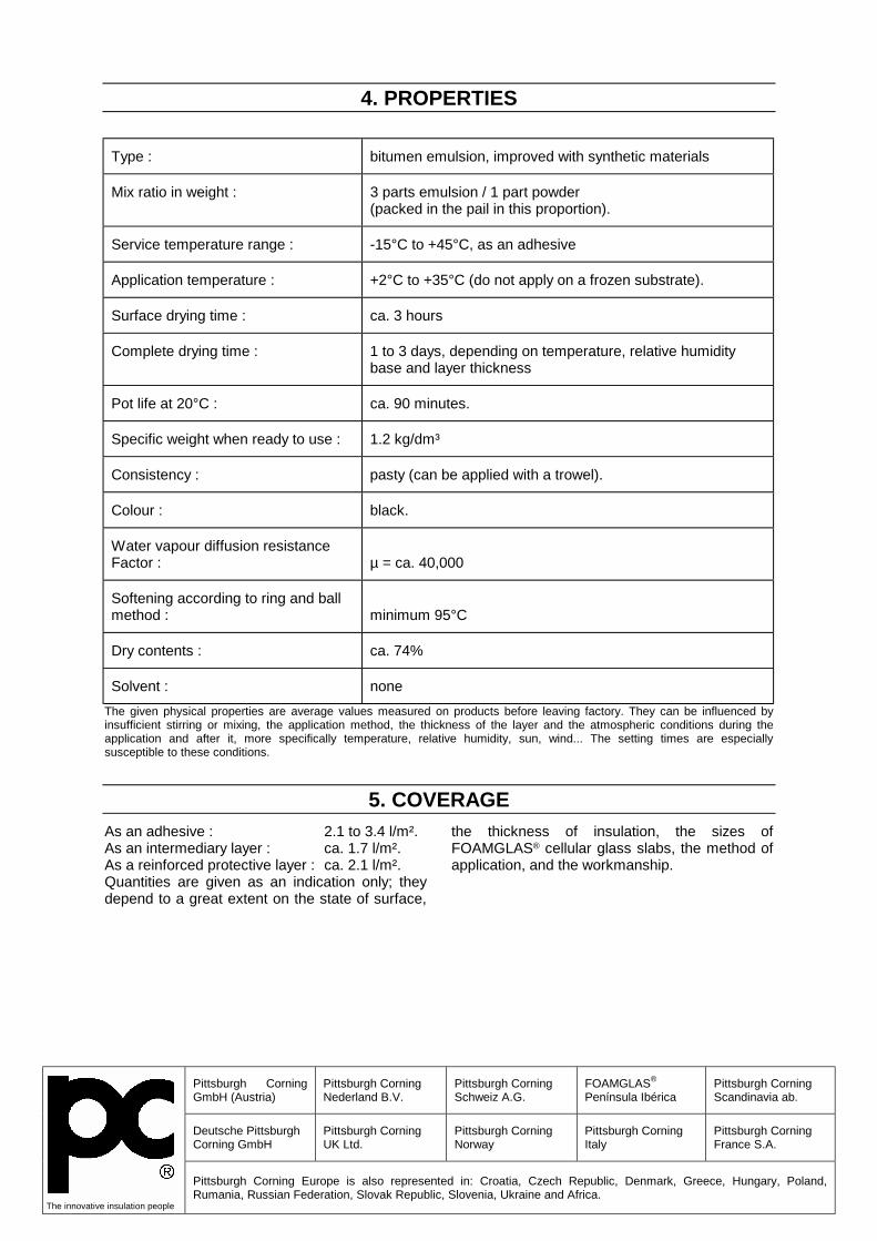
Pittsburgh Corning GmbH (Austria)
Pittsburgh Corning Nederland B.V.
Pittsburgh Corning Schweiz A.G.
FOAMGLAS® Península Ibérica
Pittsburgh Corning Scandinavia ab.
Deutsche Pittsburgh Corning GmbH
Pittsburgh Corning UK Ltd.
Pittsburgh Corning Norway
Pittsburgh Corning Italy
Pittsburgh Corning France S.A.
The innovative insulation people
Pittsburgh Corning Europe is also represented in: Croatia, Czech Republic, Denmark, Greece, Hungary, Poland, Rumania, Russian Federation, Slovak Republic, Slovenia, Ukraine and Africa.
4. PROPERTIES
Type : bitumen emulsion, improved with synthetic materials
Mix ratio in weight : 3 parts emulsion / 1 part powder (packed in the pail in this proportion).
Service temperature range : -15°C to +45°C, as an adhesive
Application temperature : +2°C to +35°C (do not apply on a frozen substrate).
Surface drying time : ca. 3 hours
Complete drying time : 1 to 3 days, depending on temperature, relative humidity base and layer thickness
Pot life at 20°C : ca. 90 minutes.
Specific weight when ready to use : 1.2 kg/dm³
Consistency : pasty (can be applied with a trowel).
Colour : black.
Water vapour diffusion resistance Factor :
µ = ca. 40,000
Softening according to ring and ball method :
minimum 95°C
Dry contents : ca. 74%
Solvent : none The given physical properties are average values measured on products before leaving factory. They can be influenced by insufficient stirring or mixing, the application method, the thickness of the layer and the atmospheric conditions during the application and after it, more specifically temperature, relative humidity, sun, wind... The setting times are especially susceptible to these conditions.
5. COVERAGEAs an adhesive : 2.1 to 3.4 l/m². As an intermediary layer : ca. 1.7 l/m². As a reinforced protective layer : ca. 2.1 l/m². Quantities are given as an indication only; they depend to a great extent on the state of surface,
the thickness of insulation, the sizes of FOAMGLAS® cellular glass slabs, the method of application, and the workmanship.

P08-1/2
PC® 58
ADHESIVE AND BASE COAT
P08
02/02
1. DESCRIPTION AND USE PC® 58 is a two-component solvent free adhesive based on bitumen emulsion improved by synthetic materials. It can be used as adhesive or as base coat. PC® 58 is flexible after hardening and unaffected by water, various salts and light acids. PC® 58 is used: - as adhesive to adhere FOAMGLAS® cellular
glass on concrete or aerated concrete roof surfaces and on sanded bituminous membranes.
- to adhere FOAMGLAS® cellular glass to itself (multilayer systems)
- as base coat between FOAMGLAS® insulation and torched-on bituminous waterproofing membranes or self-adhesive membranes.
In case of extensive and intensive vegetation, a bitumen resistant protective anti-root layer must be foreseen. PC® 58 adhesive and base coat, is not compatible with nonferrous metals such as aluminium and zinc.
2. APPLICATIONWhen used as adhesive, PC® 58 is directly applied from the drum on the substrate (coverage: about 5 kg/m²). When used as base coat, PC® 58 is also applied on the FOAMGLAS® slabs directly from the drum (coverage: about 2 kg/m²). 2.1. Surface preparation The surface to be insulated should be clean, dry and free from all traces of grease and dust. If a release agent is present on the substrate, it must be completely removed by washing. Dusting surfaces must be thoroughly swept. Except on non absorbing substrates, one should use a primer composed of one volume of PC® 58 liquid component diluted in 10 parts of tap water. For instance, in the case of 100 m² to be primed: - take 3 kg of liquid component from the drum,
dilute them in 30 litres of water - take 1 kg of solid component from the drum
and eliminate it to maintain the correct mixing ratio in the drum.
2.2. Preparation of the adhesive and base coat The powder component is progressively added to the liquid component and they are mixed in the correct ratio for about 2 minutes with an electric mixer of 750 W (no-load speed 500 to 1000 rpm) or with an air mixer equipped with a stirring paddle until a homogeneous mixture free from powder agglomerates is obtained.
2.3. Application method - Apply a primer coat composed of one volume
of PC® 58 liquid component diluted in 10 parts of water (no powder) on the evened, clean and dry concrete deck. Coverage: 0,3 kg/m²/ready-to-use mix, used as dust binder and bonding layer.
- Mix the PC® 58 adhesive and base coat with an electric mixer according to the technical data sheet and pour it directly from the drum on the substrate. Spread the PC® 58 with a squeegee. Coverage: about 5 kg/m², depending on the flatness of the deck.
- Dip the edges of the FOAMGLAS® T4 slabs in the PC® 58 to ensure the complete sealing of the joints.
- Lay the FOAMGLAS® T4 slab in the PC® 58 at a distance of about 10 cm from the edges of the already applied slabs and slide it diagonally into the open corner, so as to obtain tightly butted joints filled with bitumen emulsion.
- Pour the PC® 58 to be used as base coat on the already applied FOAMGLAS® slabs. Coverage: about 2 kg/m².
- After complete drying of the base coat, apply the double-ply roofing membrane by torching or use self-adhesive membranes.
- Apply a protective layer of gravel 15/30 on the nonwoven fleece 200 g/m².
- Water outlets and perimeter junctions in accordance with the specifications.
2.4. Cleaning the tools If PC® 58 is still wet, clean with water. If PC® 58 has cured, use mineral spirits.

3. AVAILABILITY AND STORAGE3.1. Availability PC® 58 is delivered in 32,3 kg pails (8,3 kg powder + 24,0 kg emulsion).
3.2. Storage PC® 58 must be protected from frost. When ambient temperature is high, keep away from the sun, as heat accelerates the setting. Storage: maximum 6 months.
4. PROPERTIES
Type : Bitumen emulsion, improved with synthetic materials
Mix ratio in weight : 2,9 parts emulsion/1,0 part powder (packed in the pail in this proportion)
Service temperature range : +3 °C to +35 °C
Application temperature : +2 °C to +35 °C (do not apply on a frozen substrate and consider the influence of temperature during the application)
Resistance to rain (at 20 °C/65 % relative humidity) :
about 30 minutes
Complete drying time : 1 to 3 days, depending on temperature, relative humidity, substrate and layer thickness
Pot life at 20 °C : 1 hour (after a few minutes, PC® 58 coagulates on the surface, but within about 15 minutes, it can be put into a reactive state by moving the slab).
Specific weight when ready to use : about 1,1 kg/dm³
Consistency : liquid (apply with a squeegee)
Colour : brown, black after hardening
Water vapour diffusion
resistance factor : µ = > 4,000
Dry contents : about 73,2 % in weight
Solvent : None * For some applications, higher service temperatures are admissible. Contact us if necessary. The given physical properties are average values measured on products before leaving factory. They can be influenced by insufficient stirring or mixing, the application method, the thickness of the layer and the atmospheric conditions during the application and after it, the relative humidity, sun, wind… The setting times are especially susceptible to these conditions.
5. COVERAGE5.1. As an adhesive To adhere the slabs: about 5,0 kg/m². Quantities depend on the state of the surface, the thickness of insulation, the number of cuttings,
the care taken during the application, and the workmanship. 5.2. As a base coat As a base coat: about 2,0 kg/m².
P08-2/2

1/2 P11 – 08/02
P11
08/02
1. DESCRIPTION AND USE PC® 11 is a one-component cold bituminous adhesive ready to use, especially suitable for adhering FOAMGLAS® slabs and FOAMGLAS®
READY BOARD on metal decks. PC® 11 cures to form a flexible, non-ageing adhesive with a very good adhesion to different materials.
2. APPLICATION 2.1 Surface preparation Surfaces should be clean, dry and free from oil and grease. A primer is not necessary. 2.2 Product preparation PC® 11 is ready to use. 2.3 Application method PC® 11 is generally applied to the metal surface using a double nozzle equipment. A suitable equipment for PC® 11 is the K15 pump.
The feed-pump is electrically controlled. Two beads are applied to a single corrugation crow. To obtain a good adhesion strength the FOAMGLAS® slabs must be adhered with four beads per slab or eight beads applied in parallel over one linear meter. During about 5 minutes after the application of FOAMGLAS® slabs with PC® 11, small modifications of the slab position are still possible. 2.4 Cleaning of the tools Cleaning of the extrusion pump or nozzle can be done with mineral spirits.
3 AVAILABILITY AND STORAGE3.1 Availability PC® 11 is delivered in metal drums of 24.3 l net ready to use in the working up equipment or in 2.6 l cartridges.
3.2 Storage Keep drums closed when not in use. The drums and cartridges have to be stored in a cool place protected from frost. The expiry date is mentioned on the label.
PC® 11
ADHESIVE

Pittsburgh Corning GmbH (Austria)
Pittsburgh Corning Nederland B.V.
Pittsburgh Corning Schweiz A.G.
FOAMGLAS® Península Ibérica
Pittsburgh Corning Scandinavia ab.
Deutsche Pittsburgh Corning GmbH
Pittsburgh Corning UK Ltd.
Pittsburgh Corning Norway
Pittsburgh Corning Italy
Pittsburgh Corning France S.A.
The innovative insulation people
Pittsburgh Corning Europe is also represented in: Croatia, Czech Republic, Denmark, Greece, Hungary, Poland, Rumania, Russian Federation, Slovak Republic, Slovenia, Ukraine and Africa.
4 PROPERTIES
Type: one-component cold bituminous adhesive, ready to use
Service temperature range: -5 °C to +40 °C
Application temperature: +5 °C to + 40 °C ( do not apply on frozen surfaces)
Surface drying time: about 5 to 30 min depending on the atmospheric conditions
Density: 1.15 kg/dm³
Consistency: pasty
Colour: black
Resistance against water: good acids (HCl): good (depending on the concentration and
temperature) alkalis (NaOH): good (depending on the concentration and
temperature)
petroleum solvents: low
Water vapour diffusion resistance factor: µ ≈ 50000
Dry residue (fresh mixture): ≈ 80 %
Flash point ( Pensky Martens Closed Cup): < 0 °C
Fire resistance: combustible
Solvent: petroleum solvents with low boiling point
The given physical properties are average values measured on products before leaving factory. They can be influenced by insufficient mixing, the application method, the thickness of the layer and the atmospheric conditions during the application and after it, more specifically temperature, relative humidity, sun, wind...
5 COVERAGE Eight beads applied in parallel over a length of 1 m: about 0.5 l/m². In the joints: about 0.4 l/m². Quantities depend on the job site conditions.
All information concerning the characteristics and the methods are given in good faith but imply no guarantee of responsibility on our part.

FOAMGLAS® - PC 500
1 – DESCRIPTION AND USE: PC 500 is a bituminous one component adhesive with the following properties: • Solvent poor; with a high percentage of extenders • Does not alter and remains flexible at long term • Water tight and in a large measure water vapour tight • Thixotropic • Application temperature from +5C to +40°C • Not sensible to freeze (does not contain water) • Water resistant • Application, storage, transport: easy and without risk • Ecologic, on basis of natural oils PC 500 can be used for the following applications: 1.1 To adhere FOAMGLAS® slabs, FOAMGLAS® READY BLOCK and
FOAMGLAS® BOARD panels on a continuous support; 1.2 To fully adhere the first waterproofing membrane (sanded bituminous membrane) on the
FOAMGLAS® slabs used in flat roofs. 1.3 As coating on the external surface of the FOAMGLAS® slabs used in underground walls. It can be used inside and outside, on vertical, horizontal or sloping surfaces. 2 – AVAILABILITY AND STORAGE: 2.1 Availability Metal pails of 25 kg net. 2.2 Storage PC 500 does not freeze. Before use, we recommend to store it in a room with a temperature > 10 °C, to guarantee a better viscosity for the application. Storage time: maximum 1 Year.
Product datasheet December 2004

3 - APPLICATION: 3.1. Surface preparation The surface must be flat, dry and free from oils, dust, moisture, particles, etc. If the surface remains dusty, an adhesive vernish has to be applied. 3.2. Product preparation PC 500 is a one component thixotropic adhesive ready for use. Stir the material with a stick before use (do not mix the adhesive). 3.3. Application method 3.3.1. To adhere FOAMGLAS® slabs, FOAMGLAS® READY BLOCK on flat or tapered roofs. On a continuous support, the adhesive will be applied on the whole surface with a specially adapted notched trowel (teeth of ± 10 mm, each 15 mm). The adjacent edges of each slab are dipped into the cold adhesive that has already been applied on the support. Lay each slab at a distance of ± 3 cm from the slabs that are already adhered and slide it diagonally in place by pushing slowly with one hand. A bituminous waterproofing membrane can be applied directly on the FOAMGLAS® READY BLOCK by torching. In case of FOAMGLAS® slabs, this first bituminous membrane (sanded bituminous membrane) can be sealed with the same adhesive applied with a notched trowel (teeth of 6 mm). Then the membrane has to be unrolled in the adhesive. To prevent the slipping of the insulation material, a permanent basis coating should always be foreseen in case of tapered roofs. 3.3.2 To adhere FOAMGLAS®slabs, FOAMGLAS® READY BLOCK and FOAMGLAS® READY BOARD panels used in underground walls. To adhere the slabs used in underground walls, the adhesive can be applied on the whole surface with a notched trowel (size of the teeth +/- 8 mm), or by gobs. (5 gobs/slab for FOAMGLAS® and FOAMGLAS® READY BLOCK, 8 gobs/panels FOAMGLAS® READY BOARD). The joints between the panels will be filled with the same adhesive. 3.3.3. Surface protection on FOAMGLAS® slabs used in underground walls. If used as a coating on FOAMGLAS® it can either be applied by trowel or sprayed with airless equipment. 3.3.4. To adhere FOAMGLAS® slabs, FOAMGLAS® READY BLOCK and FOAMGLAS® WALL BOARD panels used in facades. The adhesive will be applied by gobs or with a notched trowel as described in point 3.3.2. To prevent the slipping of the insulation material, a permanent basis coating should always be foreseen. In case of facades with a big height or in case of application by gobs, mechanical fixings should possibly be foreseen. Their number will be defined in function of each specification. Depending on the climate class of the building, the joints will be filled or not with the same adhesive. 3.4.Cleaning of the tools The tools should be cleaned with bitumen solvents such as spirit, petrol. 3.5. Limitations The application of the adhesive is rendered more difficult if stored at low temperature. In this case it should be warmed up slowly without direct contact of naked flame. 3.6. Cautions Adequate ventilation should be provided in closed spaces. PC 500 pails should be covered when not in use and kept away from heat and naked flame. PC 500 should not be used in atmospheres where it may be exposed to solvents, organic gases, acids or other concentrated chemicals. 4 – PROPERTIES Type : Bitumen, oils and extenders. Does not contain water. Solvents: < 6% Service temperature : from -30°C to +80°C Application temperature : from +5°C to +40°C Working time at 25°C : several days after opening of the pail if this one is tightly closed after each
utilisation. Drying time : to touch: several hours, high drying due to the thixotropy of the adhesive –
complete drying: several months Density : 1,5 kg/dm3 Colour: black Water vapour diffusion resistance factor : µ = ca. 20.000 Flash point: minimum 100 °C Resistance to alkaline and salt solutions : good Resistance to acid solutions: good (except nitric acid solutions) Resistance to oils, greases, solvents and Bituminous compounds: poor Fire resistance: combustible (Flash point > 100 °C) The physical properties given above are average values measured on products before leaving factory. These values may be affected by the quality of the support, the thickness of the layer and the atmospheric conditions during the application and after it, such as temperature, relative humidity. The setting times are especially susceptible to these conditions. Coverage To adhere the insulation slabs on flat and tapered roofs: +/- 6 kg/m² To fully adhere the membrane: +/- 2 kg/m² To adhere vertically by gobs: +/- 3 kg/m² To fully adhere vertically: +/- 4,5 kg/m² Surface protection without reinforcing (filling of the surface cells): +/- 2 kg/m² We guarantee the physical properties of Foamglas® cellular glass. Whilst great care is taken in formulating specifications, we cannot be held responsible for them due to imponderables on each specific jobsite. Please contact our services to define the application methods for special cases. Foamglas® and PC® are trademarks.

1/2 P13 – 12/03
P13
1. DESCRIPTION AND USE PC® 74 A2 is a dry factory-made mineral coating
used as a non-combustible coating with glass
fabric reinforcement and as an adhesive on
FOAMGLAS® cellular glass.
It contains a mixture of special sands, cement
and hydrated lime. PC® 74 A2 is mixed with
water; it is mainly used as a non-combustible
coating on FOAMGLAS® cellular glass, e.g. in air
conditioning installations and chilled water pipes.
The noncombustibility of PC® 74 A2 (classified
A2 according to DIN 4102) is confirmed by a
Technical Agreement.
2. APPLICATION 2.1 Pour about 5-6 litters of cold and clean water
into a mortar mixer and progressively add the
PC® 74 A2. Mix slowly with a strong stirrer
until a mixture free from agglomerates is
obtained. After about 10 minutes, rapidly stir
one more time. If necessary, add some
water.
2.2 When PC® 74 A2 is used as an adhesive, the
masonry or concrete surface to be insulated
must be clean, dry, good bearing and free
from impurities, traces of oil and mortar
edges.
2.3 When used as a coating, PC® 74 A2 is
applied on the FOAMGLAS® surface with a
spatula, in the width direction of the fabric
(coverage: about 3 kg/m²). The PC® 150 or
PC® 79G2 glass fabric is embedded with 7 to
10 cm overlapping at all seals and a second
layer of PC® 74 A2 is applied (1 kg/m²) in
order to completely cover the glass fabric.
2.4 Cleaning of the tools with water just after
application.
2.5 Limitations: Ambient and surface
temperatures cannot fall below +5 °C during
application and drying phase. Application
cannot be carried out in direct sunlight.
3. AVAILABILITY AND STORAGE 3.1 Availability
PC® 74 A2 is delivered in liner paper bag of 25
kg.
3.2 If stored in a dry place, can be kept for 3
years (production date: see side). Protect
from humidity (contains cement).
PC® 74 A2

Pittsburgh Corning GmbH (Austria)
Pittsburgh Corning Nederland B.V.
Pittsburgh Corning Schweiz A.G.
FOAMGLAS® Península Ibérica
Pittsburgh Corning Scandinavia ab.
Deutsche Pittsburgh Corning GmbH
Pittsburgh Corning UK Ltd.
Pittsburgh Corning Norway
Pittsburgh Corning Italy
Pittsburgh Corning France S.A.
The innovative insulation people
Pittsburgh Corning Europe is also represented in: Croatia, Czech Republic, Denmark, Greece, Hungary, Poland, Rumania, Russian Federation, Slovak Republic, Slovenia, Ukraine and Africa.
4. PROPERTIES
Type:
Mineral coating
Service temperature range:
-30 °C to +80 °C
Application temperature:
+5 °C to +35 °C during application until complete drying
Drying at 20 °C/65 %:
dry in surface after 24 hours, completely dry (capable of bearing) after 72 hours
Application time at 20 °C:
about 3-4 hours
Density:
Mixed (fresh) : 1.4 kg/dm³ Cured coating: < 1.5 kg/dm³
Colour:
light grey
Water vapour diffusion resistance factor:
µ ≈ 15
Fire reaction:
non combustible according to DIN 4102.
Solvent:
none
The given physical properties are average values measured on products before leaving factory. They can be influenced by insufficient stirring or mixing, the application method, the thickness of the layer and the atmospheric conditions during the application and after it, more specifically temperature, relative humidity, sun, wind… The setting times are especially susceptible to these conditions.
5. COVERAGECoverage: about 4 kg/m² (as coating). Quantities are given as an indication only, they
depend to a great extent on the state of the
surface, the thickness of insulation and the
method of application.

1/2 P14 – 06/04
P14
1. DESCRIPTION AND USE PC® HOTMELT ADHESIVE is a one component solvent and water free adhesive based on hot bitumen, specially modified to improve its fire behaviour. PC® HOTMELT ADHESIVE is used : - to adhere FOAMGLAS® cellular glass to a metal deck;
- to adhere FOAMGLAS® cellular glass to itself; - as a top layer on FOAMGLAS® before applying a membrane by torching. PC® HOTMELT ADHESIVE is heated before application and hardens by cooling down.
2. APPLICATION
2.1 Surface preparation The surface (metal deck) to be insulated should be clean, dry and free from all traces of grease, rust, dust, oil, moisture and scale. The surface shall be primed with PC® PRIMER 3A. 2.2 Preparation of the adhesive The preparation is similar to the case of hot bitumen. PC® HOTMELT ADHESIVE is heated in a bitumen bath at a temperature that does not exceed 220°C. It is important to avoid overheating the product.
2.3 Application method PC® HOTMELT ADHESIVE is applied on FOAMGLAS® blocks by dipping one main face and two edges in the bitumen bath. The FOAMGLAS® blocks are then immediately applied on the metal deck against the previous ones, making the joints as narrow and as tight as possible. They are kept in position during the time needed for the cooling down of the PC® HOTMELT ADHESIVE. 2.4 Cleaning of the tools If tools are used they can be cleaned with mineral spirits.
3. AVAILABILITY AND STORAGE
3.1 Availability PC® HOTMELT ADHESIVE is delivered in 20 kg blocks, possibly on pallets of 54 blocks. Dimension of the blocks: 48 x 32 x 11 cm
3.2 Storage PC® HOTMELT ADHESIVE is not affected by negative temperature. Rain or condensation water on the package surface should be limited to avoid water in the bath when heating the product. Storage: maximum 5 years.
PC® HOTMELT
ADHESIVE

Pittsburgh Corning GmbH (Austria)
Pittsburgh Corning Nederland B.V.
Pittsburgh Corning Schweiz A.G.
FOAMGLAS® Península Ibérica
Pittsburgh Corning Scandinavia ab.
Deutsche Pittsburgh Corning GmbH
Pittsburgh Corning UK Ltd.
Pittsburgh Corning Norway
Pittsburgh Corning Italy
Pittsburgh Corning France S.A.
The innovative insulation people
Pittsburgh Corning Europe is also represented in: Croatia, Czech Republic, Denmark, Greece, Hungary, Poland, Rumania, Russian Federation, Slovak Republic, Slovenia, Ukraine and Africa.
4 PROPERTIES
Type: modified bitumen with additives to improve the fire behaviour (one component product)
Service temperature range: - 20 °C to + 50 °C
Application temperature: - 10 °C to + 35 °C
Setting time a few minutes
Density: 1.2 kg/dm³
Colour: black
Water vapour diffusion resistance factor: more than 20.000
Ring and ball method
Softening point:
Penetration at 25 °C:
95 °C 0.1 mm
Fire behaviour: - better than ordinary oxidized bitumen; - has passed the Factory Mutual calorimeter test in a FOAMGLAS® system applied on metal deck.
The given physical properties are average values measured on products before leaving factory. They can be influenced by insufficient mixing, the application method, the thickness of the layer and the atmospheric conditions during the application and after it, more specifically temperature, relative humidity, sun, wind...
5. COVERAGE As an adhesive on metal deck: ca 1.2 kg/m² To adhere FOAMGLAS® insulation to itself: ca 2.5 kg/m² To prepare the top surface to torch on the membrane: ca 2.5 kg/m²
To fill the joints between 600x450x100xblocks: ca 1 kg/m² (to be adapted according to the layer thickness). Quantities are given as an indication only; they depend on the state of the surface, the method of application, the workmanship, etc.

1/2 P18 – 12/03
P18
1. DESCRIPTION AND USE PC® 18 ADHESIVE is a one-component cold bituminous adhesive ready to use. PC® 18 ADHESIVE is used for the insulation of chilled water lines. It is used to seal the longitudinal and circumferential joints between the FOAMGLAS®
shells. PC® 18 ADHESIVE cures to form a flexible, non-ageing adhesive with a very good adhesion to different materials.
2. APPLICATION
2.1 Surface preparation Surfaces must be dry, clean and free from all traces of grease, rust, dust and oil. An anticorrosion layer is recommended or imposed (see regulations in force). 2.2 Product preparation PC® 18 ADHESIVE is ready to use. 2.3 Application method
PC® 18 ADHESIVE is applied on the longitudinal and circumferential joints of the FOAMGLAS® shells with an extrusion gun. The internal diameter of this gun must range from 50 to 51 mm. The beads are applied on one face of each joint before firmly pressing the shells into position, against each other. 2.4 Cleaning of the tools Cleaning of the extrusion gun is done with mineral spirits.
3 AVAILABILITY AND STORAGE
3.1 Availability PC® 18 is delivered in Alu colored foil (refill) of 600 ml (12 units per package) and also in polyethylene cartridges of 310 ml (12 units per package).
3.2 Storage Keep the product in a cool place (maximum + 40°C) protected from frost. The expiry date is mentioned on the label.
PC® 18 ADHESIVE

Pittsburgh Corning GmbH (Austria)
Pittsburgh Corning Nederland B.V.
Pittsburgh Corning Schweiz A.G.
FOAMGLAS® Península Ibérica
Pittsburgh Corning Scandinavia ab.
Deutsche Pittsburgh Corning GmbH
Pittsburgh Corning UK Ltd.
Pittsburgh Corning Norway
Pittsburgh Corning Italy
Pittsburgh Corning France S.A.
The innovative insulation people
Pittsburgh Corning Europe is also represented in: Croatia, Czech Republic, Denmark, Greece, Hungary, Poland, Rumania, Russian Federation, Slovak Republic, Slovenia, Ukraine and Africa.
4. PROPERTIES
Type: one-component cold bituminous adhesive, ready to use
Service temperature range: -20 °C to +40 °C
Application temperature: -5°C °C to + 40 °C ( do not apply on frozen surfaces)
Surface drying time: For beads of 10 mm diameter: between half an hour and one hour at ambient temperature.
Density: 1.1 kg/dm³
Consistency: pasty
Colour: black
Resistance against Water: good Acids (HCl): good (depending on the concentration and
temperature) Alkalis (NaOH): good (depending on the concentration and
temperature)
Petroleum solvents: low
Water vapour diffusion resistance factor: µ ≈ 40000
Dry residue (fresh mixture): ≈ 80 %
Flash point ( Pensky Martens Closed Cup): < 0 °C
Fire resistance: combustible
Solvent: petroleum solvents with low boiling point
The given physical properties are average values measured on products before leaving factory. They can be influenced by the application method, the thickness of the layer and the atmospheric conditions during the application and after it, more specifically temperature, relative humidity, sun, wind...
5. COVERAGE The beads of 10 mm diameter require 80 ml/linear meter of joint. Quantities depend on the state of the surface, the thickness of insulation, the number of cuttings, shells or segments, the care during
application and the workmanship. All information concerning the characteristics and the methods of application are given in good faith but imply no guarantee of responsibility on our part.

PC ® Low Temperature Anti-Abrasive PRODUCT DATA SHEET
IMPORTANT: Material safety data sheets are available and should be read before using this product.
Page 1 of 1 Copyright© 2010 Pittsburgh Corning Europe 02/2010
DESCRIPTION PC® Low Temperature Anti-Abrasive is a water based anti-abrasive based on modified polyurethane resins. It reduces abrasion from vibrating piping or vessels. Its strong adhesive qualities through a wide temperature range permit its use on extremely low temperature equipment. The surface of the FOAMGLAS® insulation, treated with PC® Low Temperature Anti-Abrasive is hard, durable and provides resistance to wear compared to movement of the insulation substrate. The surface cells (inside) of FOAMGLAS® slabs, segments and shells are coated with this product. APPLICATION Surface preparation The surface to be insulated should be clean, dry and free from all traces of grease, rust, dust, oil and moisture. Preparation of the product Stir well and do not thin the product. Keep container closed when not in use to prevent surface skinning. Application method Apply to clean, dry inner surface of FOAMGLAS® insulation. Allow to dry before installing insulation. This product can be applied with brush or spray. Brush: use clean paintbrushes. Apply in a single heavy, full brush coat at recommended coverage. (2.5 to 3.7m²/l) Spray: can be applied with or without compressed air. A full and even coat should be obtained. Ventilate adequate. Cleaning of the tools If still wet, use warm soapy water. When dry, use mineral spirits or chlorinated solvent. AVAILABILITY AND STORAGE Availability PC® Low Temperature Anti-Abrasive is available in metal containers of 17 kilogram. Storage Store between 4°C and 40°C. Shelf-life: 2 years.
TYPICAL PROPERTIES*
Type Water based coating
with polyurethane resins
Colour Off white Service temperature range -196°C to +93°C
Application temperature Minimum 4°C
Density 1.60kg/dm³
Drying time (25°C)
Set to touch: 45 to 90 minutes
Dry through: 2 to 3 hours
Fire resistance Flammable; Flash point: over 100°C
* Properties subject to change. Consult Pittsburgh Corning Europe. COVERAGE 2.5 to 3.7m²/l. A coat should be between 0.41 and 0.28mm thick. This consumption is an indication and may depend on the processing method and the craftsmanship. The information contained herein is accurate and reliable to the best of our knowledge. But, because Pittsburgh Corning has no control over installation workmanship, accessory materials or conditions of application, no express or implied warranty of any kind, including those of merchantability or fitness for a particular purpose, is made as to the performance of an installation containing Pittsburgh Corning products. In no event shall Pittsburgh Corning be liable for any damages arising because of product failure, whether incidental, special, consequential or punitive, regardless of the theory of liability upon which any such damages are claimed. Pittsburgh Corning provides written warranties for many of its products, and such warranties take precedence over the statements contained here. FOAMGLAS® is a registered trademark owned by Pittsburgh Corning. Pittsburgh Corning Corporation 800 Presque Isle Drive Pittsburgh, PA 15239-2799 USA Toll free: 800-545-5001 Phone: (724)327-6100 Fax: (724)387-3806 Pittsburgh Corning Europe S.A./N.V. (EMEA Headquarters) Altbertkade 1, 3980 Tessenderlo Belgium Phone: +32-13-611-415 Fax: +32-13-351-567
www.foamglas.com

PC® HIGH TEMPERATURE ANTI-ABRASIVE
P21
1. DESCRIPTION AND USE PC® HIGH TEMPERATURE ANTI-ABRASIVE is a dry one-component mix of modified calcium sulphate with some inert mineral fillers. PC® HIGH TEMPERATURE ANTI-ABRASIVE is applied on FOAMGLAS® cellular glass to reinforce its surface for high temperature applications and when needed for dual temperature applications. When dry it forms a hard surface protection filling the surface cells of the insulation and protects them against
abrasion. Even at very high temperatures this film remains resistant to abrasion and can be used up to +350°C. PC® HIGH TEMPERATURE ANTI-ABRASIVE is used as an adhesive to prefabricate shells, segment and elbows where service temperature exceeds +120°C or for temperatures below -180°C where inorganic materials should be used.
2. APPLICATION.2.1. Surface preparation. The surface should be clean, dry and free from all traces of grease, rust, dust, oil, and moisture. 2.2. Product preparation. - Mix PC® HIGH TEMPERATURE ANT-ABRASIVE progressive with pure water in the ratio of 6.5 to 7.5 litres of water to 10 kg of Anti-Abrasive powder using a mixer. - Pour powder into the water and never the opposite. - Once initial mixing is complete, let stand for two to three minutes. - Mix a second time and the product is ready for application. Note The temperature of the water affects the setting and working time. 2 3. Application method. Use only clean tools. PC® HIGH TEMPERATURE ANTI-ABRASIVE has a short period of plasticity and stiffens rapidly. It sets approximately 30 minutes after preparation. It is important not to prepare too large quantities in advance. Never add water to a mixture that has already
began to set. 2.3.1. Anti-abrasive. The mixture is brush applied on the bore of the FOAMGLAS® shells, and these may not be applied on the pipe until the product is completely dry. For pipe insulation shells, it is recommended to choose an inside diameter of 3 to 4 mm larger than the outside diameter of the piping, considering the anti-abrasive layer thickness. 2.3.2. Adhesive. The mixture is applied by brush or trowel on the two surfaces to be adhered together. Press the pieces firmly together and let the assembled piece completely dry before cutting or abrading it. 2.3.3. High temperature reinforced coating. The 1-st layer of the mixture into which the glass fabric PC® FABRIC 79 G2 has been embedded is applied to surface. The 2-nd layer of the mixture should be applied before the 1-st layer sets. 2.4. Cleaning the tools. Wet product : with water. Dry product : by scraping.
3. AVAILABILITY AND STORAGE.3.1. Availability PC® HIGH TEMPERATURE ANTI-ABRASIVE is delivered in polyethylene lined paper bags of 40 kg net.
3.2. Storage. Out of humidity. Shelf life: 12 months
1/2 P21 – 11/03

4. PROPERTIES
Type : gypsum cement with inert fillers.
Mix ratio : 6.5 to 7.5 kg of water to 10 kg powder
Service temperature range : +20°C to +350°C and for cryogenic applications (below -180°C)
Application temperature : +5°C to +40°C
Working time at +25°C : about 30 minutes.
VICAT setting time at +20°C between 60 and 120 minutes
Complete drying by dry weather : about 24 hours.
Density : of the powder (dry) : 0.7 kg/dm³ of the applied bore coating or adhesive : 1.0 kg/dm³
Water vapour diffusion resistance Factor :
µ < 30 (not applicable as water vapour barrier)
Colour : dark grey
Fire resistance : incombustible. The given physical properties are average values measured on products before leaving factory. They can be influenced by insufficient mixing, the application method and the atmospheric conditions during the application and after it, more specifically temperature, relative humidity, sun, wind...
5. COVERAGEAnti-abrasive: 0.4 to 0.8 kg of dry powder per m² Adhesive: 1.6 to 2.0 kg of dry powder per m²
Quantities are given as an indication only; they depend to a great extent on the state of surface, the thickness of insulation, the sizes of FOAMGLAS® cellular glass slabs, the method of application, the workmanship, etc.
Pittsburgh Corning GmbH (Austria)
Pittsburgh CorningNederland B.V.
Pittsburgh CorningSchweiz A.G.
FOAMGLAS® Península Ibérica
Pittsburgh CorningScandinavia ab.
Deutsche Pittsburgh Corning GmbH
Pittsburgh CorningUK Ltd.
Pittsburgh CorningNorway
Pittsburgh Corning Italy
Pittsburgh CorningFrance S.A.
The innovative insulation people
Pittsburgh Corning Europe is also represented in: Croatia, Czech Republic, Denmark, Greece, Hungary, Poland, Rumania, Russian Federation, Slovak Republic, Slovenia, Ukraine and Africa.

1/2 P22 – 08/02
P22
08/02
1. DESCRIPTION AND USE PC® 85 POWDER is a mineral based, totally inorganic powder that has been especially designed for filling the open surface cells of FOAMGLAS® cellular glass when used for the insulation of liquid oxygen, liquid nitrogen or hot tank bottoms. This powder, together with
appropriate interleaving layers (felt or mineral sheet) can achieve the desired load distribution even if the compressive strength reached with this system is slightly inferior to the reference value under EN 826 or ASTM C 240-91 conditions.
2. APPLICATION2.1. Surface preparation The FOAMGLAS® insulation surface should be clean, dry and free from all traces of grease, rust, dust, oil, moisture, scale, etc. 2.2. Product preparation Make sure that PC® 85 POWDER has been kept in a dry state. 2.3. Application method PC® 85 POWDER is poured dry onto one face of the FOAMGLAS® slab and spread by means of a rubber scraper in order to fill all open cells. The slab is then gently turned over and applied. (The powder sticks to the slab during this
manipulation). The upper face of the slab is then powdered with PC® 85 POWDER and evened out. 2.4. Cleaning the tools Dry dusting. 2.5. Limitations No particular limitations. 2.6. Cautions In order to evacuate the dust, an adequate ventilation will be installed. Preferably wear dust mask.
3. AVAILABILITY AND STORAGE3.1. Availability In polyethylene lined paper bags of 40 kg.
3.2. Storage In a dry place. Storage is limited to 6 months.
PC® 85 POWDER

Pittsburgh Corning GmbH (Austria)
Pittsburgh Corning Nederland B.V.
Pittsburgh Corning Schweiz A.G.
FOAMGLAS® Península Ibérica
Pittsburgh Corning Scandinavia ab.
Deutsche Pittsburgh Corning GmbH
Pittsburgh Corning UK Ltd.
Pittsburgh Corning Norway
Pittsburgh Corning Italy
Pittsburgh Corning France S.A.
The innovative insulation people
Pittsburgh Corning Europe is also represented in: Croatia, Czech Republic, Denmark, Greece, Hungary, Poland, Rumania, Russian Federation, Slovak Republic, Slovenia, Ukraine and Africa.
4. PROPERTIES
Type : mineral in impalpable powder form, one component
Service temperature range : from -200°C to +350°C.
Application temperature : from +5°C to +40°C.
Density : 0.70 kg/dm³
Colour : white
Fire resistance : incombustible The given physical properties are average values measured on products before leaving factory. They can be influenced by the application method, the thickness of the layer and the atmospheric conditions during the application and after it, more specifically temperature, relative humidity, sun, wind...
5. COVERAGEAbout 1.2 kg per m² of cellular glass to cover. Quantities given should be considered as an indication only; they depend greatly on the state
of surface, the method of application, the workmanship, etc.

Page 1 of 2 FI-120 Rev 06/2009Replaces Rev 12/2007
PITTCOTE® 300 FINISH PRODUCT DATA SHEET
IMPORTANT: MATERIAL SAFETY DATA SHEETS ARE AVAILABLE AND SHOULD BE READBEFORE USING THIS PRODUCT.
DESCRIPTION:PITTCOTE® 300 finish is a vapor and weather barrierasphalt coating especially formulated for use withFOAMGLAS® insulation in the low to moderatetemperature range.
PITTCOTE® 300 finish is available in trowel and spraygrades. Spray grade is a special order. Application is byspray, trowel or glove.
*TYPICAL PROPERTIES:PROPERTY
Color: BlackWeight: kg/l (lbs/gal) 1.02 (8.5)Solids, %wt (%vol.): Spray: Trowel:
61.5 to 65.5 (50.7 to 54)66 to 70 (56.5 to 60)
**Coverage: l/m2 (gal/100 ft2) mm (mils):
2.5 to 3.3 (6 to 8)2.4 to 3.3 (95 to 130)
Application Temperature,material: °C (°F): 10 to 49 (50 to 120)Service Temp: °C (°F) -40 to 93 (-40 to 200)Solvent: Mineral SpiritsFlash Point, minimum PMCC, wet, °C (°F): 38.8 (102)ASTM E84 Flame Spread: Smoke Development:
510
Water Vapor Permeability, ASTM E96, Procedure E: perm-cm (perm-in) perms @ 1.3mm (50mils)
0.16 (0.003)7.27
***Drying Time, hrs: Touch 2; Firm 24;Through 14 days
* Properties subject to change. Consult Pittsburgh Corning Corporation.** Allowance should be made for losses during application.***Will vary with weather conditions and thickness.
SURFACE PREPARATION:The FOAMGLAS® insulation surface should be dry, freeof frost, oil and grease and below 60°C (140°F). Dust orother loose material should be removed
MATERIAL PREPARATION:This material should be thoroughly mixed prior touse. Be sure you have read and understand allinstructions, cautions, and Material Safety DataSheets contents before using.
Store PITTCOTE® 300 finish in a warm area for easyapplication in cold weather. Application temperatureshould be 10°C to 49°C (50°F to 120°F). Do Not heatcan directly with an open flame. Do Not thin toovercome cold temperatures effects. Thin withmineral spirits for brush application only. Do Notthin more than 5% 1 liter/20 liter (1qt/5 gal).
APPLICATION ABOVE GROUND:See CAUTION. Spray or trowel a tack coat of 0.8 to1.2 liters/m² (2 to 3 gal/100ft²) of PITTCOTE® 300finish to FOAMGLAS® insulation. Embed PC®Fabric 79 into the wet coat overlapping all fabricjoints 10 cm (4 in). Smooth fabric and stretch toremove wrinkles. Apply a second coat after the firstcoat dries at a rate of 1.6 to 2.0 liters/m² (4 to 5gal/100ft²). Surface temperature should be 5°C to60°C (40°F to 140°F) and material temperatures of10°C to 49°C (50°F to 120°F). Spray application can bemade with air or airless equipment. For airless useGraco 45:1 pump with mastic gun 451 orifice withreverse-a-clean attachment or equivalent. Linesshould be 19mm (¾ in) I.D., and pump should beequipped with a hydraulic ram; delivery pressure atgun should be about 1300 psi. Although PITTCOTE®300 finish has excellent weather resistance; it willdegrade over time when exposed to UV light.Pittsburgh Corning Corporation recommends thatthe PITTCOTE® 300 finish be coated with aluminumroof coating or covered with metal or other UVresistant jacketing.
APPLICATION UNDERGROUND:See CAUTION. On underground lines, flashpolyester film from lapping or areas of PITTWRAP®jacketing to be coated. When using PITTWRAP® SSjacketing, see jacketing data sheet FI-179A. Be sureFOAMGLAS® insulation surface is free of moisture,dust and any other loose material before applying.

PITTCOTE® 300 FINISH PRODUCT DATA SHEET
Page 2 of 2 FI-120 Rev 06/2009Replaces Rev 12/2007
Trowel or use plastic gloves a tack coat of 0.8 to 1.2liters/m² (2 to 3 gal/100ft²) and embed PC® Fabric 79,lapping edges 10 cm (4 in). Apply a second coat of 0.8 to1.2 liters/m² (2 to 3 gal/100ft²) and a second layer of fabric.Apply a top coat of 0.8 to 1.2 liters/m² (2 to 3 gal/100ft²) sothat no fabric is visible when dry. Do not backfill untilcoating is dry.
CLEAN-UP AND DISPOSAL:Mineral spirits or kerosene.See Material Safety data Sheets for proper disposal.
STORE IN COOL AREA FOR COMBUSTIBLES
PACKAGING:19 liter (5 gal.) containers208 liter (55 gal.) containers
The information contained herein is accurate and reliable to the best of our knowledge.But, because Pittsburgh Corning Corporation has no control over installationworkmanship, accessory materials or conditions of application, NO EXPRESS ORIMPLIED WARRANTY OF ANY KIND, INCLUDING THOSE OFMERCHANTABILITY OR FITNESS FOR A PARTICULAR PURPOSE, IS MADE as tothe performance of an installation containing Pittsburgh Corning products. In no event shallPittsburgh Corning be liable for any damages arising because of product failure, whetherincidental, special, consequential or punitive, regardless of the theory of liability uponwhich any such damages are claimed. Pittsburgh Corning Corporation provides writtenwarranties for many of its products, and such warranties take precedence over thestatements contained herein.
FOAMGLAS®, PC®, and PITTCOTE®, are federally registeredtrademark owned by Pittsburgh Corning Corporation
Pittsburgh Corning Corporation800 Presque Isle Drive Pittsburgh, PA 15239-2799USAToll Free: 800-545-5001Phone: (724)327-6100Fax: (724)387-3806http://www.foamglas.com/
Pittsburgh Corning Europe S.A./ N.V.(EMEA Headquarters)Albertkade 13980 TessenderloBelgiumPhone: +32-13-611-415Fax: +32-13-351-567
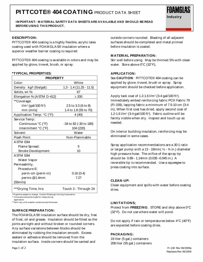
Page 1 of 2 FI-138 Rev 06/2009aReplaces Rev 06/2009
PITTCOTE® 404 COATING PRODUCT DATA SHEET
IMPORTANT: MATERIAL SAFETY DATA SHEETS ARE AVAILABLE AND SHOULD BE READBEFORE USING THIS PRODUCT.
DESCRIPTION:PITTCOTE® 404 coating is a highly flexible, acrylic latexcoating used with FOAMGLAS® insulation where asuperior weather barrier coating is required
PITTCOTE® 404 coating is available in colors and may beapplied by glove, trowel, brush, or spray.
*TYPICAL PROPERTIES:PROPERTY
Color: WhiteDensity: kg/l (lbs/gal): 1.3 - 1.4 (11.25 - 11.5)Solids, wt %: 67Elongation % (ASTM D-412) 200**Coverage: l/m2 (gal/100 ft2)
mm (mils)2.5 to 3.3 (6 to 8)
1.4 to 1.8 (55 to 70)Application Temp: °C (°F): 4 (40)Service Temp: Continuous °C (°F) Intermittent °C (°F)
-34 to 82 (-30 to 180)104 (220)
Solvent: WaterFlash Point Non-FlammableASTM E84 Flame Spread: Smoke Development:
510
ASTM E84 Water VaporPermeability, Procedure E: perm-cm (perm-in)
perms @ 1.4mm(55mils)
0.16 (0.4)7.27
***Drying Time, hrs: Touch 3 - Through 24* Properties subject to change. Consult Pittsburgh Corning Corporation.** Allowance should be made for losses during application.***Will vary with weather conditions and thickness.
SURFACE PREPARATION:The FOAMGLAS® insulation surface should be dry, freeof frost, oil and grease. Insulation should be fitted so thejoints are tight and without broken or rounded corners.Any surface variations between blocks should beeliminated by rubbing the insulation smooth. Excesssealant or adhesive should be removed from theinsulation surface. Inside corners should be canted and
outside corners rounded. Blasting of all adjacentsurfaces should be completed and metal primedbefore insulation is coated.
MATERIAL PREPARATION:Stir well before using. May be thinned 5% with cleanwater. Store above 0°C (32°F).
APPLICATION:See CAUTION: PITTCOTE® 404 coating can beapplied by glove, trowel, brush or spray. Sprayequipment should be checked before application.
Apply tack coat of 1.2-1.6 l/m2 (3-4 gal/100 ft2).Immediately embed reinforcing fabric PC® Fabric 79(FI-159), lapping fabric a minimum of 7.5-10 cm (3-4in), When first coat has dried, apply second coat of1.2-1.6 l/m2 (3-4 gal/100 ft2). Fabric outline will befaintly visible when dry. Inspect and touch up asneeded.
On interior building insulation, reinforcing may beeliminated in some cases.
Spray application recommendations are a 30:1 ratioor larger pump with a 13 - 19mm( ½ - ¾ in.) diameterhigh pressure hose. The orifice of the spray tipshould be 0.89 - 1.14mm (0.035 -0.045 in.) Areversible tip is recommended. Use a squeegee topress coating into surface.
CLEAN-UP:Clean equipment and spills with water before coatingdries.
LIMITATIONS;Protect from FREEZING. STORE and ship above 0°C(32 F). Do not use where water will pond.
Do not apply if rain or temperatures below 4°C (40°F)are expected before coating dries.
PACKAGING:19 liter (5 gal.) containers208 liter (55 gal.) containers
PITTCOTE® 404 COATING PRODUCT DATA SHEET
Page 2 of 2 FI-138 Rev 06/2009aReplaces Rev 06/2009
The information contained herein is accurate and reliable to the best of our knowledge. But,because Pittsburgh Corning Corporation has no control over installation workmanship, accessorymaterials or conditions of application, NO EXPRESS OR IMPLIED WARRANTY OF ANYKIND, INCLUDING THOSE OF MERCHANTABILITY OR FITNESS FOR A PARTICULARPURPOSE, IS MADE as to the performance of an installation containing Pittsburgh Corningproducts. In no event shall Pittsburgh Corning be liable for any damages arising because ofproduct failure, whether incidental, special, consequential or punitive, regardless of the theory ofliability upon which any such damages are claimed. Pittsburgh Corning Corporation provideswritten warranties for many of its products, and such warranties take precedence over thestatements contained herein.
FOAMGLAS®, PC®, and PITTCOTE®, are federally registered trademark owned by PittsburghCorning Corporation
Pittsburgh Corning Corporation800 Presque Isle Drive Pittsburgh, PA 15239-2799 USAToll Free: 800-545-5001Phone: (724)327-6100Fax: (724)387-3806http://www.foamglas.com/
Pittsburgh Corning Europe S.A./ N.V.(EMEA Headquarters)Albertkade 13980 TessenderloBelgiumPhone: +32-13-611-415Fax: +32-13-351-567

Page 1 of 2 FI-164 Rev 06/2009Replaces Rev 12/2007
PITTSEAL® 444N SEALANT PRODUCT DATA SHEET
IMPORTANT: MATERIAL SAFETY DATA SHEETS ARE AVAILABLE AND SHOULD BE READBEFORE USING THIS PRODUCT.
DESCRIPTION:PITTSEAL® 444N sealant is a specially formulated butylsealant used for sealing joints in FOAMGLAS® insulationsystems, and to seal protrusions and metal jacket laps.
This single component sealant is certified to meetstainless steel service requirements of MIL-I-24244 andNRC Regulatory Guide 1.36.
PITTSEAL® 444N sealant is compatible with a widevariety of coatings.
USES:-Joint sealant in FOAMGLAS® insulation pipe coveringand between insulation blocks.-Bedding compound behind FOAMGLAS® insulation.-Anti-Abrasive cushion in vibrating systems.-Seal protrusions and metal jacket laps.
*TYPICAL PROPERTIES:PROPERTY
Color: GreyWeight: kg/liter (lbs/gal): 1.6 (13.0)Solids, Vol %: 90Solvent: Mineral SpiritsFlash Point (Cleveland): °C (°F) >204 (>400)**Flame Spread, ASTM E84 5 Smoke Development 5
Application Temp: °C (°F) 4 to 38(40 to 100)
***Service Temp: °C (°F) -56.6 to 82-70 to 180
Intermittent to: °C (°F) 122 (250)Permeability, ASTM E96: perm cm (in)
0.013 (0.008)
Coverage: .33 m²/l = 3 mm(12.8 ft²/gal = 1/8 in film)
(smooth surface)
0.67 m²/l = 1.5 mm film(25.6 ft²/gal = 1/16 in)
6.7 m/l = 5 cm X 3 mmjoint
(77 ft/gal = 2 in x 1/8 in)Volatile Organic Content:(VOC) 98 g/l (0.82 lbs/gal)[Complies with SCAQMD VOC limits specified in Table 1 ofUSGBC LEED® for New Construction & Major Renovationv2.2 (IEQ Credit 4.1) for sealants]
*Typical properties at time of printing, subject to change **Tested with FOAMGLAS® insulation under application conditions.
***At sealant location.
APPLICATION:DO NOT THIN. Apply with trowel, knife or caulkinggun. All surfaces should be dry and free of dust, loosescale, oil, grease and frost. Apply sufficient materialto both surfaces and press surfaces together firmly toobtain a complete seal. Joints less than or equal to 3mm (1/8 in) are desirable. Do not use this or any othersealant to fill large voids from poor fitting. Blocks orjoints should be rubbed to obtain good fit beforeapplication of sealant. If a coating is to be applied, cutoff any squeezed-out sealant flush with surface.When sealing laps of metal jacketing, maintain a 1.5mm (1/16 in) minimum thickness. Allow to cure oneweek before placing in hot service.
PITTSEAL® 444N sealant works easily over thesuggested application range. To facilitate applicationat low temperature, keep containers in a heatedlocation or loosen lid and warm by indirect heat. DONOT HEAT containers with flame or direct heat.
CLEAN-UP AND DISPOSAL:Tools should be cleaned with mineral spirits.See Material Safety Data Sheet for proper disposal.
LIMITATIONS:DO NOT use in applications where solvent odorcould affect food taste or flavor. May pick up dustwhen exposed. Solvent may attack some organicfoams. Product should not be exposed to UV light.
ACCEPTANCE:Chemically acceptable for USDA use in processing orstorage areas for meat or poultry food productsprepared under federal inspection.
PACKAGING:355ml (10 fl. oz.)cartridges (12/case) 19 liter (5 gallon) containers

PITTSEAL® 444N SEALANT PRODUCT DATA SHEET
Page 2 of 2 FI-164 Rev 06/2009Replaces Rev 12/2007
The information contained herein is accurate and reliable to the best of our knowledge. But,because Pittsburgh Corning Corporation has no control over installation workmanship, accessorymaterials or conditions of application, NO EXPRESS OR IMPLIED WARRANTY OF ANYKIND, INCLUDING THOSE OF MERCHANTABILITY OR FITNESS FOR A PARTICULARPURPOSE, IS MADE as to the performance of an installation containing Pittsburgh Corningproducts. In no event shall Pittsburgh Corning be liable for any damages arising because ofproduct failure, whether incidental, special, consequential or punitive, regardless of the theory ofliability upon which any such damages are claimed. Pittsburgh Corning Corporation provideswritten warranties for many of its products, and such warranties take precedence over thestatements contained hereinFOAMGLAS® and PITTSEAL® are federally registered trademarks owned by Pittsburgh CorningCorporationLEED® is a registered trademark of U.S. Green Building Council.
Pittsburgh Corning Corporation800 Presque Isle Drive Pittsburgh, PA 15239-2799 USAToll Free: 800-545-5001Phone: (724)327-6100 Fax: (724)387-3806http://www.foamglas.com/
Pittsburgh Corning Europe S.A./ N.V.(EMEA Headquarters)Albertkade 13980 TessenderloBelgiumPhone: +32-13-611-415 Fax: +32-13-351-567

1/2 P45 – 08/02
P45
08/02
1. DESCRIPTION AND USE PC® 80M MORTAR is a two-component inorganic mortar based on specially formulated glass powder and fillers for component one and modified silica dispersion for component two. Components to be mixed in the ratio of 100 part component one with 23 (Trowel grade) or 26 (Spray grade) part component two by weight.
PC® 80M MORTAR is used to adhere FOAMGLAS® cellular glass to itself within a large temperature range. When the temperatures are very low, very high, or when they cycle rapidly, using the laminated technique that consists of embedding a specific reinforcement in the adhesive layer.
2. APPLICATION2.1. Surface preparation The surface to be insulated should be clean, dry and free from all traces of grease, rust, dust, oil, and moisture. 2.2. Adhesive preparation 100 parts (by weight) of powder are added into 23 parts of liquid (26 parts of liquid when using spraying equipment - SPRAY BOY - PUTZMEISTER) and are thoroughly mixed with a stirring paddle in an electric or air-powered mixer until a homogenous mixture is obtained. NEVER add Portland cement, water or other materials to liquid, powder or mortar mix. Temperature affects curing and working time. It should be as close to 25°C as possible. NEVER thin or rework but discard any mortar that has begun to set. The mortar is creamy and non sagging up to thicknesses of about 7 mm. 2.3. Application method PC® 80M MORTAR may be applied to either one or both surfaces. A notched trowel (notches 5 x 5
mm, distance 5 mm) is recommended for close fitting surfaces. Protect work from rain, frost and excessive temperatures until set. Application temperature is between +5 and +45°C. 2.4. Cleaning the tools Tools can be cleaned with water before mortar sets, set mortar can be removed mechanically. 2.5. Limitations Do not put the installation into service earlier than 8 days after application. 2.6. Cautions Avoid breathing liquid component mist and powder dust, avoid contact with eyes (flush thoroughly with water) and prolonged contact with skin. Exposure can be minimised by wearing safety goggles and rubber or plastic-coated gloves.
3. AVAILABILITY AND STORAGE3.1. Availability Powder component : polyethylene lined paper bags, 25 kg net. Liquid component : polyethylene bottles, 5.75 kg for trowel grade or 6.5 kg net for spray grade.
3.2. Storage Store in a dry place, out of direct sunlight, the liquid must also be protected from freezing. Storage temperature limits : +5 to +45°C. Shelf life : 2 years.
PC® 80M MORTAR
TROWEL GRADE - SPRAY GRADE

Pittsburgh Corning GmbH (Austria)
Pittsburgh Corning Nederland B.V.
Pittsburgh Corning Schweiz A.G.
FOAMGLAS® Península Ibérica
Pittsburgh Corning Scandinavia ab.
Deutsche Pittsburgh Corning GmbH
Pittsburgh Corning UK Ltd.
Pittsburgh Corning Norway
Pittsburgh Corning Italy
Pittsburgh Corning France S.A.
The innovative insulation people
Pittsburgh Corning Europe is also represented in: Croatia, Czech Republic, Denmark, Greece, Hungary, Poland, Rumania, Russian Federation, Slovak Republic, Slovenia, Ukraine and Africa.
4. PROPERTIES
Type : two component inorganic mortar
Mix ratio in weight : powder : 100 liquid : trowel grade 23 spray grade 26
Service temperature range : has been tested from -196°C to +320°C
Application temperature : from +5 to +45°C
Working time at 25°C : about 30 minutes.
Density in kg/dm³ : powder (bulk density) : 1.09 liquid : 1.31 mixed mortar (fresh) : 1.46 cured mortar : 1.43
Vicat setting (22°C) : about 100 minutes
Modulus of elasticity (by compressive strength method)
at ambient temperature :800 N/mm² at -120°C : 1100 N/mm²
Linear coefficient of thermal expansion :
from +20 to -120°C : 8 x 10⁻⁶ / °C
Water vapour diffusion resistance factor :
µ = +/- 30
Flash point : none
Combustibility : incombustible The given physical properties are average values measured on products before leaving factory. They can be influenced by mixing equipment, insufficient mixing, the application method, the thickness of the layer and the atmospheric conditions during the application and after it, more specifically temperature, relative humidity, sun, wind... The setting times are especially susceptible to these conditions.
5. COVERAGEAs an adhesive : about 5 kg/m² To make a "laminated" adhered layer with a glass fabric embedded in the PC® 80M MORTAR : about 8 kg/m². Allowance should be made for loss during application.
Quantities are given as an indication only; they depend to a great extent on the state of surface, the thickness of insulation, the sizes of FOAMGLAS® cellular glass slabs, the method of application, and the workmanship.

Page 1 of 1 FI-159 Rev 06/2009Replaces Rev 11/2007
PC® FABRIC 79 PRODUCT DATA SHEET
IMPORTANT: MATERIAL SAFETY DATA SHEETS ARE AVAILABLE AND SHOULD BE READBEFORE USING THIS PRODUCT.
DESCRIPTION:PC® Fabric 79 is an open mesh, synthetic fabric forreinforcing PITTCOTE® 404 (FI-138) or PITTCOTE® 300(FI-120) coating over FOAMGLAS® insulation. The largemesh openings allow the coating to easily penetrate andbond to the insulation and fabric. The thickness of thefabric assures that the proper thickness of the coating isapplied and gives the required strength. The highelongation accommodates large and mechanicalmovements without rupture and allows maximummovement of the coating.
*TYPICAL PROPERTIES:PROPERTY
Composition: 100% polyesterWeight g/m², (oz/yd²): 94.3 ± 14.2
(2.78 ± 0.42)Meshes per cm (per in.): 2.4 (6 x 5.5)Mesh Opening, mm (in): 3.18 (0.125)Thickness, mm (inches): 0.67 ± 0.13
(0.026 ± 0.005)Ball Burst min. kg/cm² (psi): 7.0 (100)Width, in (m): 1 (39-40)Length, m (yd): 45.7 (50)Weight/Roll, kg, (lbs): 3.9 ± 0.6
(8.7 ± 1.3)Fire Resistance: Combustible
*Typical properties at time of printing, subject to change.Consult Pittsburgh Corning Corporation.
APPLICATION:PC® Fabric 79 is cut to fit piping, vessel or shape,allowing a minimum of 5 to 8cm (2 to 3 in.) overlap at allseams. Fabric should be cut to fit closely withoutwrinkles. Scissors or shears are recommended for cutting.Apply a tack coat of PITTCOTE® 404 coating orPITTCOTE® 300 finish to FOAMGLAS® insulationaccording to the recommendations. Immediately smooththe Fabric into the coating so it is free of wrinkles.Additional coating is applied according to the specificproduct data sheet being referenced.
FABRIC SHOULD NOT SHOW THROUGH THESECOND APPLICATION OF WET COATING BUTTHE OUTLINE OF FABRIC WILL BE VISIBLE INDRIED COATING.
When used with PITTCOTE® 404 coating, the tackcoat can be sprayed through the fabric and workedwith a squeegee. This saves labor and makes theoperation cleaner. The second coat is applied afterthe tack coat takes its initial set.
LIMITATIONS:Keep fabric stored in a dry location.
PACKAGING:Fiberboard box
The information contained herein is accurate and reliable to the best of our knowledge.But, because Pittsburgh Corning Corporation has no control over installationworkmanship, accessory materials or conditions of application, NO EXPRESS ORIMPLIED WARRANTY OF ANY KIND, INCLUDING THOSE OFMERCHANTABILITY OR FITNESS FOR A PARTICULAR PURPOSE, IS MADE as tothe performance of an installation containing Pittsburgh Corning products. In no event shallPittsburgh Corning be liable for any damages arising because of product failure, whetherincidental, special, consequential or punitive, regardless of the theory of liability uponwhich any such damages are claimed. Pittsburgh Corning Corporation provides writtenwarranties for many of its products, and such warranties take precedence over thestatements contained herein.
FOAMGLAS®, PC® and PITTCOTE® are federally registered trademark owned byPittsburgh Corning Corporation
Pittsburgh Corning Corporation800 Presque Isle Drive Pittsburgh, PA 15239-2799USAToll Free: 800-545-5001Phone: (724)327-6100 Fax: (724)387-3806http://www.foamglas.com/
Pittsburgh Corning Europe S.A./ N.V.(EMEA Headquarters)Albertkade 13980 TessenderloBelgiumPhone: +32-13-611-415 Fax: +32-13-351-567

1/2 P52 – 08/02
P52
08/02
1. DESCRIPTION AND USE
PC® 150 is an open mesh, alkali resistant glass fabric for reinforcing mastic finishes over FOAMGLAS® insulation and other insulations. The large mesh openings (about 3 mm) allow the heavy mastics or mineral coating to easily penetrate and bond to the insulation and to the
fabric. The thickness of the fabric assures that the proper thickness of the coating is applied and gives the required strength. Its tensile resistance is greater than that of the polyester PC® Fabric 79 P but the deformation is lower. It is especially suited for use with PC®74A2
2. APPLICATION
2.1. Application method PC® 150 is cut to fit shape or vessel, allowing a minimum of 10 cm overlap at all seams. Use scissors for cutting. A tack coat is applied on the insulation according to the coating manufacturer's recommendations. After application of a tack coat on the insulation, the fabric PC® 150 is immediately smoothed without wrinkles into this first layer. A second layer of coating is applied as the first one, according to the manufacturer's recommendations.
PC® 150 should not show through wet coating but outline of fabric will be visible in dried coating. The second coat is applied after the tack coat takes its initial set. 2.2. Limitations Compatibility of PC® 150 with the coating should be determined, especially in the case of a vapour barrier coating.
3. AVAILABILITY AND STORAGE
3.1. Availability PC® 150 is delivered in 1 m x 50 m rolls. Roll weight: approx. 8.5 kg.
3.2. Storage Store in a dry place.
PC® 150

Pittsburgh Corning GmbH (Austria)
Pittsburgh Corning Nederland B.V.
Pittsburgh Corning Schweiz A.G.
FOAMGLAS® Península Ibérica
Pittsburgh Corning Scandinavia ab.
Deutsche Pittsburgh Corning GmbH
Pittsburgh Corning UK Ltd.
Pittsburgh Corning Norway
Pittsburgh Corning Italy
Pittsburgh Corning France S.A.
The innovative insulation people
Pittsburgh Corning Europe is also represented in: Croatia, Czech Republic, Denmark, Greece, Hungary, Poland, Rumania, Russian Federation, Slovak Republic, Slovenia, Ukraine and Africa.
4 PROPERTIES
Type : large mesh glass fabric with styrolacrylate.
Service temperature range : -35°C to + 80°C
Weight : 165 g/m²
Mesh openings : 3.6 x 3.4 mm
Centre wire to centre wire: 5.0 x 4.0 mm
Meshes/ dm² : 500
Tensile across warp : 42 N/mm across fill : 38 N/mm
The given physical properties are average values measured on products before leaving factory. They can be influenced by the application method and the atmospheric conditions during the application and after it, more specifically temperature, relative humidity, sun, wind...
5. COVERAGESurfaces to be coated must be increased with 10% to take into account the overlaps. Coverage : 1.1 m²/m² Quantities are given as an indication only; they depend to a great extent on the state of surface,
the thickness of insulation, the sizes of FOAMGLAS® cellular glass slabs, the method of application, and the workmanship.

1/2 P60 – 08/02
P60
08/02
1. DESCRIPTION AND USE PITTWRAP® STANDARD is a jacket specially designed to cover FOAMGLAS® insulation applied on underground pipes. It consists of a prefabricated Iaminate containing a bitumen impregnated glass fabric and an integral
aluminium foil, sandwiched between three layers of modified bitumen mastic. The exposed surface of PITTWRAP® jacket is coated with a protective plastic film and the inner surface with a special release paper.
2. APPLICATIONPITTWRAP® STANDARD is applied around FOAMGLAS® cellular glass in a cigarette type wrap and is heat-sealed at the overlaps of the longitudinal direction. Butt-joints are covered with a 10 cm wide strip that is also heat sealed with a torch at the edges around the circumference.
Step-by-step instructions for applying PITTWRAP® jacket
1 Remove release paper 2 Heat leading edge 3 Press PITTWRAP® around FOAMGLAS®
insulation 4 Burn off plastic film at edge C for a distance of
80 mm back 5 Soften PITTWRAP® at edge D until material is
tacky 6 Lap edge D over edge C a minimum of 50 mm
pressing PITTWRAP® jacket tightly against FOAMGLAS® insulation
7 Heat seal seam at the lap until PITTWRAP® jacket softens and flows together
D
C
D
C
50mm
Nota: Overlapping should be set up as to avoid water penetration
Step-by-step instructions for application of Butt Joints
1 Remove release paper from jacket butt strip 2 Burn off plastic film 50 mm on each side of joint.
Apply enough heat to soften PITTWRAP® jacket 3 Heat and soften entire contact surface of butt
strip 4 Apply strip around butt joint lapping strip 50 mm
and heat sealing edge of 50 mm lap 5 Heat seal edges of butt strip around
circumference at edges B and C
BUTT STRIPCONTACT AREA
100 mm
B C
100 mm
PIPE
PITTWRAP®
BUTT STRIP
3. AVAILABILITY AND STORAGE3.1. Availability PITTWRAP® STANDARD : 0.61 x 15.24 m² PITTWRAP® STANDARD strips : 0.10 x 15.24 m²
3.2. Storage Out of sun and humidity
PITTWRAP® STANDARD

Pittsburgh Corning GmbH (Austria)
Pittsburgh Corning Nederland B.V.
Pittsburgh Corning Schweiz A.G.
FOAMGLAS® Península Ibérica
Pittsburgh Corning Scandinavia ab.
Deutsche Pittsburgh Corning GmbH
Pittsburgh Corning UK Ltd.
Pittsburgh Corning Norway
Pittsburgh Corning Italy
Pittsburgh Corning France S.A.
The innovative insulation people
Pittsburgh Corning Europe is also represented in: Croatia, Czech Republic, Denmark, Greece, Hungary, Poland, Rumania, Russian Federation, Slovak Republic, Slovenia, Ukraine and Africa.
4. PROPERTIES
Service temperature range : 0°C to +90°C
Application temperature : from -5°C to +40°C
Weight : 3.25 kg/m²
Resistance to soil acids : Good
The given physical properties are average values measured on products before leaving factory. They can be influenced by the application method and the atmospheric conditions during the application and after it, more specifically temperature, relative humidity, sun, wind...
5. COVERAGESurfaces to be coated must be increased to take into account the overlaps of the longitudinal direction (circumference + 50 mm).
Quantities depend to a great extent on the state of surface, the thickness of insulation, the sizes of FOAMGLAS® cellular glass slabs, the method of application, and the workmanship.

1/2 P61 – 08/02
P61
08/02
1. DESCRIPTION AND USE PITTWRAP® SELF-SEALING jacket consists of a special bituminous resin, reinforced with a woven glass fabric, covered with an aluminised mylar film and a release paper. PITTWRAP® SELF-SEALING Jacket is a self-sealing, non-metallic sheet for protecting
underground FOAMGLAS® insulation systems. Manual pressure seals the jacket without the use of a torch or heater. PITTWRAP® SELF-SEALING Jacket may also be factory-applied on the insulation.
2. APPLICATION2.1. Application method PITTWRAP® SELF-SEALING jacket shall be applied in butt strips (like PITTWRAP® STANDARD). The jacket shall be cut to a length equal to the circumference, increased by a minimum of 50 mm. Before application, the release paper shall be carefully removed without damaging the jacket and avoiding that impurities or dust will dirty the adhesion surface. Care shall be taken to align the jacket at the side of the piping. The jacket shall be applied in such a way that the upper lip is pointing downwards. Blisters in the jacket shall be removed immediately after adhesion. The adhesion surface shall be smoothed by roller. The jacket strips shall be applied width against width with their joints protected by a cover strip of PITTWRAP® SELF-SEALING. The cover strips shall be cut to a length equal to the circumference, increased by an overlap of 50 mm. Before placing the butt strip, apply a bead of PITTSEAL® 444 along the edge of the longitudinal joint in the area to be covered by the butt strip. Embed butt strip end in the sealant. After application, inspect all joints and smooth down any loose areas with a roller. Where the outside diameter of the insulation changes, i.e. at the connections of flanges, valves and elbows, the PITTWRAP® SELF-
SEALING jacket can be replaced by a mastic finish, such as PITTCOTE® 300, reinforced with two glass fabrics. The mastic finish shall be applied onto the bituminous part of the PITTWRAP® SELF-SEALING and not onto the polyester. The joint is made as follows : 1 Stop the jacket 100 mm from the juncture. 2 Take a cover strip and place it with its polyester side against the FOAMGLAS® pipe covering. 3 Adhere the cover strip onto one half of the jacket and onto one half of the already placed returned cover strip. 4 Apply the mastic and the fabric onto the bituminous part of the back-turned cover strip. 2.2. Limitations - This product is designed for underground use only. For applications above ground on loops, etc., consult Pittsburgh Corning. - Observe practical precautions when backfilling so not to puncture jacket. - Store in warm locations to facilitate handling in cool weather. - During exceptionally hot weather, when large diameter pipe is involved, it may be necessary to provide additional temporary support for shop applied jacket by the judicious use of several wraps of fibre glass reinforced strapping tape over the jacket and lapping itself at least 50%.
3. AVAILABILITY AND STORAGE3.1. Availability PITTWRAP® SELF-SEALING : 0.61 x 15.24 m² strips : 0.10 x 15.24 m²
3.2. Storage Out of sun and humidity
PITTWRAP®
SELF-SEALING

Pittsburgh Corning GmbH (Austria)
Pittsburgh Corning Nederland B.V.
Pittsburgh Corning Schweiz A.G.
FOAMGLAS® Península Ibérica
Pittsburgh Corning Scandinavia ab.
Deutsche Pittsburgh Corning GmbH
Pittsburgh Corning UK Ltd.
Pittsburgh Corning Norway
Pittsburgh Corning Italy
Pittsburgh Corning France S.A.
The innovative insulation people
Pittsburgh Corning Europe is also represented in: Croatia, Czech Republic, Denmark, Greece, Hungary, Poland, Rumania, Russian Federation, Slovak Republic, Slovenia, Ukraine and Africa.
4. PROPERTIES
Service temperature limits on the outside of insulation :
-5°C to +80°C
Application temperature : Without primer : min. 10°C With primer : min. 0°C
Thickness : 1.8 - 1.9 mm
Weight : 1.8 - 2.0 kg/m²
Roll weight : 16.8 - 18.6 kg
Colour : Silver
Permeability (ASTM E96) : 0.002 Perm inches
Resistance to water : alkalis : acids : petroleum solvents :
good good good poor
Fire : combustible The given physical properties are average values measured on products before leaving factory. They can be influenced by the application method and the atmospheric conditions during the application and after it, more specifically temperature, relative humidity, sun, wind...
5. COVERAGESurfaces to be coated must be increased to take into account the overlaps of the longitudinal direction (circumference + 50 mm).
Quantities depend to a great extent on the state of surface, the thickness of insulation, the sizes of FOAMGLAS® cellular glass slabs, the method of application, and the workmanship.

TEROSTAT-PC
P70
02/05
1. DESCRIPTION AND USE Terostat-PC is a sprayable- and gunable, one component sealant, coating and adhesive, based on silane modified polymer ( MS® -Polymer ), which cures by reaction with moisture to a soft elastic product. Terostat-PC may be applied by spray and gun. Terostat-PC is free of solvents, isocyanates, silicones and PVC, and is odourless. It is compatible with suitable paint systems and coatings. The coating demonstrates good weathering, UV and mechanical resistance, as well as excellent
chemical resistance. Terostat-PC is not sensitive to temperature changes, and has excellent crack-bridging capacities. Terostat-PC is a flame retardant sealant and coating. Terostat-PC is used as a coating, adhesive and sealant in Pittsburgh Corning FOAMGLAS®
-Terostat insulation system, providing a weather protection, sealing and water vapour barrier.
2. APPLICATION2.1. Surface preparation The substrates must be clean, dry oil and grease free. 2.2. Product preparation Low material temperatures of the sealant will lead to an increase of viscosity, resulting in a lower extrusion rate. This can be avoided by bringing the sealant up to room temperature prior to application. If substrates are too cold temperatures may fall below the dew point causing condensation. This can be avoided by bringing the substrates up to room temperature. 2.3. Application method 2.3.1 Foamglas®-Terostat elements will be supplied.(Foamglas elements covered with a factory applied layer of extruded Terostat-PC) 2.3.2 As a coating Apply a coat of 3 to 4 kg/m² It may be applied by trowel cut of drums or by cartridge. The coating is smoothed using trowel, spatula or gloves immediately after application.
Use of a smoothing agent will avoid drag marks on the surface. 2.3.3 As a joint sealant - Joints should be rubbed before application of sealant - Best applied by extrusion gun or from cartridges. Trowel or knife should be used for restricted areas. - Sealant to be applied to one or both surfaces; press firmly in order to obtain a complete seal. - Smooth squeezed out sealant flush with the Terostat-PC coating, giving a perfect seal. 2.4. Cleaning the tools For cleaning application equipment contaminated with uncured Terostat-PC we recommend the use of Cleaner + Diluent A, D or FL. 2.5. Limitations Avoid application at freezing conditions 2.6. Cautions Avoid eye contact
3. AVAILABILITY AND STORAGE3.1. Availability Drums , cartridges
3.2. Storage Frost –sensitive: no Recommended storage temperature: 10°C to 25°C Shelf-live: 12 months in original packaging
P70 1/2

4. PROPERTIES
Colour: Grey
Consistency: Pasty, thixotropic
Density: Approx. 1.5 g/cm³
Skin formation time *: Approx. 10 minutes
Cure rate: Approx. 4 mm/24h
Shore-A-hardness (DIN 53505)* Approx. 40
Tensile strength *: (according to DIN 53504)
Approx. 2.5 MPa
Elongation at break *: (according to DIN 53504) Stress at 100% elongation *: (according to DIN 53504)
Approx. 220% Approx. 1.2 MPa
UV-resistance: Test method: UV source: Distance to the specimen: Test period:
No significant changes of the surface dry UV Osram Vitalux 300 W 25 cm 6 weeks
Application temperature : 5°C to 40°C
In service temperature range: Short exposure (up to 1h): * DIN 50014 standard climate
- 50°C to +100°C 120°C 23°C, 50% relative air humidity
Water vapour permeance (EN 12086):
0.015 perm-in at 3 mm dry thickness (tested at 23°C and 85% RH)
Surface burning characteristics (ASTM E84):
Flame spread 15 Smoke developed 35 ( tested at 2mm thickness on 6,4 mm inorganic reinforced cement board )
Fire class : M1 ( tested as per NFP 92-512 and NFP 92-501 ( France))
5. COVERAGEAs a coating: About 4.5 kg/m² to obtain a coat of 3 mm As a sealant: use a 7 mm diameter bead from extrusion gun or cartridge.
Quantities are given as an indication only; they depend to a great extent on the state of surface, the thickness of insulation, the sizes of FOAMGLAS® cellular glass slabs, the method of application, the workmanship etc.
P70 2/2

PC ® 700K PRODUCT DATA SHEET
IMPORTANT: Material safety data sheets are available and should be read before using this product.
Page 1 of 1 Copyright© 2010 Pittsburgh Corning Europe 02/2010
DESCRIPTION PC® 700K is a combination of a two-component inorganic mortar and a glass cloth reinforcement to protect the FOAMGLAS® insulation system to suffer from thermal cracking. It is ideal when the temperatures are very low, very high, or when they cycle rapidly. The mortar is based on specially formulated glass powder, fillers and modified silica dispersion. The thickness of the coating (approximately 3 kg/m²) gives the coating its required strength. APPLICATION Surface preparation The surface to be insulated should be clean, dry and free from all traces of grease, rust, dust, oil and moisture. Application method FOAMGLAS® elements will be supplied precoated with PC® 700K. They should be installed like every other normal, non-coated FOAMGLAS® slab. AVAILABILITY Availability PC® 700K is available as a pre applied coating for all FOAMGLAS® material. Weight Depends on the FOAMGLAS® material where PC 700K coating is applied to. Pittsburgh Corning Corporation 800 Presque Isle Drive Pittsburgh, PA 15239-2799 USA Toll free: 800-545-5001 Phone: (724)327-6100 Fax: (724)387-3806
TYPICAL PROPERTIES*
Type
two component inorganic mortar and
glass fabric with styrolacylate
Service temperature range -196°C to +320°C
Colour dark grey
Density 1,43 kg/dm³ Compressive strength > 10 N/mm²
Tensile strength > 0.5 N/mm²
Modulus of elasticity
At ambient temperature: 800N/mm²
At -120°C:
1100 N/mm²
Linear coefficient of thermal expansion
from +20 to -120°C: 8 x 10⁻⁶/°C
Water vapour diffusion resistance factor µ = ± 30
Fire resistance non-flammable
Combustibility incombustible * Properties subject to change. Consult Pittsburgh Corning Europe. The information contained herein is accurate and reliable to the best of our knowledge. But, because Pittsburgh Corning has no control over installation workmanship, accessory materials or conditions of application, no express or implied warranty of any kind, including those of merchantability or fitness for a particular purpose, is made as to the performance of an installation containing Pittsburgh Corning products. In no event shall Pittsburgh Corning be liable for any damages arising because of product failure, whether incidental, special, consequential or punitive, regardless of the theory of liability upon which any such damages are claimed. Pittsburgh Corning provides written warranties for many of its products, and such warranties take precedence over the statements contained here. FOAMGLAS® is a registered trademark owned by Pittsburgh Corning. Pittsburgh Corning Europe S.A./N.V. (EMEA Headquarters) Altbertkade 1, 3980 Tessenderlo Belgium Phone: +32-13-611-415 Fax: +32-13-351-567
www.foamglas.com

Page 1 of 1 Copyright © 2009 Pittsburgh Corning Corporation FI-268 Rev 10/2009Replaces Rev ----
PITTCOURSE™ 100 PRODUCT DATA SHEET
IMPORTANT: MATERIAL SAFETY DATA SHEETS ARE AVAILABLE AND SHOULD BE READBEFORE USING THIS PRODUCT.
DESCRIPTION:PITTCOURSE™ 100 High Performance Bitumen DampProof Course (DPC) is a modified bitumen, non metallicsheet for use as a DPC between layers of FOAMGLAS®insulation tank base insulation systems.
PITTCOURSE™ 100 DPC consists of a modified bituminouscompound reinforced with a polyester base, and finishedwith fine silica sand.
*TYPICAL PROPERTIES:PROPERTY
Manufactured in compliance with BS6398-1983.Color: BlackThickness: mm, (mils) 3 (118)Weight: kg/m2, (lbs/ft2) 4 ± 0.25 (0.82 ± 0.05)Width: mm, (in) 1000/±20 (39.4/±0.8)Roll length: m, (ft) 8 ±0.1(26.2 ±.0.3)Nominal Roll Area: m2, (ft2) 8 (86)Nominal Roll Coverage: m2, (ft2) 8 (86)Application Temperature, min: °C,(°F) 10, (50)
Softening Point of Bitumen Coating°C (°F) 80 - 120 (176 - 248)
Flow Resistance of BitumenCoating °C (°F) 90 – 160 (194 - 320)
Low Temperature Flexibility °C(°F)
5 (41)Bend around a 30 mm
mandrill without cracking* Properties subject to change. Consult Pittsburgh Corning .
FIELD APPLICATION:Apply first layer of the appropriate grade FOAMGLAS®HLB insulation per specification. All joints of the insulationmust be tightly butted.
Apply a single layer of PITTCOURSE™ 100 DPC over theFOAMGLAS® HLB insulation block. PITTCOURSE™ 100DPC should be placed in a single layer on theFOAMGLAS® HLB insulation block. The DPC should beinstalled with edges tightly butted and no voids.
The next layer of FOAMGLAS® HLB insulation block isthen carefully placed over the felt layer with joints firmlybutted together with no voids. The insulation joints of thislayer are staggered from the joints of the first layer ofinsulation.
Successive courses of FOAMGLAS® HLB insulation blockare installed in this manner with single layer ofPITTCOURSE™ 100 DPC, over each course of block. Applylayers in this fashion to achieve specified systemthickness.
The joints of each successive layer of FOAMGLAS®HLB insulation block shall be staggered from thepreceding layer.
The final course of FOAMGLAS® HLB insulation iscovered with a single layer of PITTCOURSE™ 100 DPCapplied as in the same manner as previouslydescribed.
LIMITATIONS:Do not use on above ambient tank applications.
PITTCOURSE™ 100 should not be stored where it isliable to come in contact with hydrocarbon solventssuch as petroleum spirit and diesel oil or other organicsolvents.
STORAGE:PITTCOURSE™ 100 rolls must be stored on end andunder cover and be protected from mechanicaldamage. Store PITTCOURSE™ 100 in a heated areafor cold weather applications, and keep dry prior touse and during installation.
IMPORTANT:Transport and store upright. Keep dry and out ofdirect exposure to the elements. Store pallets on aflat surface only. Stand rolls on end only. Do notstore more than one pallet high.
The information contained herein is accurate and reliable to the best of our knowledge.But, because Pittsburgh Corning has no control over installation workmanship, accessorymaterials or conditions of application, NO EXPRESS OR IMPLIED WARRANTY OF ANYKIND, INCLUDING THOSE OF MERCHANTABILITY OR FITNESS FOR APARTICULAR PURPOSE, IS MADE as to the performance of an installation containingPittsburgh Corning products. In no event shall Pittsburgh Corning be liable for anydamages arising because of product failure, whether incidental, special, consequential orpunitive, regardless of the theory of liability upon which any such damages are claimed.Pittsburgh Corning provides written warranties for many of its products, and suchwarranties take precedence over the statements contained hereFOAMGLAS® is a federally registered trademark owned by Pittsburgh Corning
Pittsburgh Corning800 Presque Isle Drive Pittsburgh, PA 15239-2799 USAToll Free: 800-545-5001 Phone: (724)327-6100 Fax: (724)387-3806http://www.foamglas.com/
Pittsburgh Corning Europe S.A./ N.V. (EMEA Headquarters)Albertkade 1 3980 Tessenderlo BelgiumPhone: +32-13-611-415 Fax: +32-13-351-567
Pittsburgh Corning Asia / Pacific(Asia Headquarters)PARK LUXE HONGO 100129-4, HONGO 2-CHOME, BUNKyO-KUTOKYO 113-0033 JAPANTelephone / Fax: 81-50-7554-0248

PC 47 ADHESIVE Product Data Sheet IMPORTANT: Material safety data sheets are available and should be read before using this product
DESCRIPTION AND USE PC 47 ADHESIVE is a synthetic fibre-reinforced, solvent free air-drying one-component, bitumen based ADHESIVE for adhering FOAMGLAS® to one another. PC 47 ADHESIVE can be used for the following applications: - spot bonding on FOAMGLAS® wall boards in cavity walls - full surface area bonding of FOAMGLAS® T4+ slabs in flooring - finish sealing of FOAMGLAS® surfaces in flooring APPLICATION Substrate preparation The substrate should be clean and free of form release oil or loosely adhering paint residues. A priming coat of one part PC 47 ADHESIVE and 10 parts water shall be applied and allowed to dry on concrete, masonry and highly absorbent substrates.
Preparation of the adhesive The product is ready for use (do not stir).
Application method PC 47 ADHESIVE is to be applied by trowel in dabs or over the full surface area of the FOAMGLAS® slabs or boards. For full surface area bonding, a notched trowel (with 8 to 10 mm teeth) should be used. In both cases, the ADHESIVE is applied to the insulation boards and not to the substrate.
Coverage - Wall: spot bonding 2.5 kg/m² - Floor: full surface area, flush filled joints 4 to 5 kg/m² - Surface finish sealing in flooring 1.5 kg/m² The above quantities are only indicative, because the actual coverage depends on surface evenness, number of cut-outs, flush filling of joints, method of application, and construction site conditions.
Cleaning the tools Tools should be cleaned with water before curing, and with white spirit after curing.
Restrictions PC 47 ADHESIVE is unsuitable: - for use on metal and non-absorbent substrates - for gluing a second FOAMGLAS® insulation layer - for gluing to a sealing layer - for gluing boards to subsequently applied rubbed-down thin bed plaster
AVAILABILITY AND STORAGE Availability PC 47 ADHESIVE is delivered in drums of 35 kg.
Storage - frost-free, protected from sunlight - maximum 6 months Solvent free, not classified as toxic PROPERTIES
Base modified bitumen emulsion Consistency pasty Service temperature range +0°C to +40°C Application temperature +5°C to +40°C Softening temperature (ring/ball method) approx. 110°C
Pot life at 25°C several days Drying time at 25°C approx. 1 hour Complete drying time at 25°C several days Density approx. 1.10 kg/dm³ Dry matter content approx. 58% by weight Colour black Water vapour diffusion resistance factor µ = 1000
REGULATIONS Not subject to notification under the hazardous substances regulations. Declaration matrix D093.06 and Safety Data Sheet 91/155/EEC can be obtained from Pittsburgh Corning Europe. The information contained herein is accurate and reliable to the best of our knowledge. But, because Pittsburgh Corning has no control over installation workmanship, accessory materials or conditions of application, no express or implied warranty of any kind, including those of merchantability or fitness for a particular purpose, is made as to the performance of an installation containing Pittsburgh Corning products. In no event shall Pittsburgh Corning be liable for any damages arising because of product failure, whether incidental, special, consequential or punitive, regardless of the theory of liability upon which any such damages are claimed. Pittsburgh Corning provides written warranties for many of its products, and such warranties take precedence over the statements contained here. FOAMGLAS® is a registered trademark owned by Pittsburgh Corning. Pittsburgh Corning 800 Presque Isle Drive Pittsburgh, PA 15239-2799 USA Toll Free: 800-545-5001 Phone: (724)327-6100 Fax: (724)387- 3806 http://www.foamglas.com Pittsburgh Corning Europe S.A./ N.V. (EMEA Headquarters) Albertkade 1 3980 Tessenderlo Belgium Phone: +32-13-611-415 Fax: +32-13-351-567 Pittsburgh Corning Asia / Pacific (Asia Headquarters) Park Luxe Hongo 1001 29-4, Hongo 2-Chome, Bunkyo-KU Tokyo 113-0033 Japan Telephone / Fax: 81-50-7554-0248
Copyright © 2010 Pittsburgh Corning Corporation Revised 06/2009 – Replaces all previous

www.foamglas.com
Pittsburgh Corning Europe N.V./S.A.Headquarter Europe, Middle East and Africa (EMEA)Albertkade 1, B-3980 Tessenderlo Phone: +32 13 661 721Fax: +32 13 667 854
Pittsburgh Corning USA(Corporate Headquarters)800 Presque Isle Drive Pittsburgh, PA 15239 Phone: 1-724-327-6100Fax: 1-724-387-3807
April 2010 Pittsburgh Corning reserves the right to modfiy the technical specifications at any time. The information contained herein is accurate and reliable to the best of our knowledge. The currently valid information can be found in the product catalog on our homepage: www.foamglas.com.FOAMGLAS® is a registrated trademark owned by Pittsburgh Corning.