infit 762 infit 763 instruction manual
TRANSCRIPT

InFit® 762InFit® 763
Instruction manual
52 400 140
917620001
InFit® 762 / InFit® 763 3
© 03/04 Mettler-Toledo GmbH, CH-8606 Greifensee 52 400 140Printed in Switzerland
InFit® 762InFit® 763
Instruction manual
4 InFit® 762 / InFit® 763
52 400 140 © 03/04 Mettler-Toledo GmbH, CH-8606 Greifensee Printed in Switzerland
Contents
1. Introduction..........................................................................5
2. Important notes ....................................................................52.1 General.................................................................................52.2 Safety precautions..................................................................5
3. Description of product...........................................................6
4. Installation and start up procedures.......................................74.1 Installation ............................................................................74.1.1 Mounting in reactors ..............................................................74.1.2 Installing and removing the housing ........................................84.1.3 Installing and removing the electrode .......................................84.1.4 Attaching the cable...............................................................114.1.5 Checking for correct installation .............................................114.2 Start up...............................................................................124.2.1 Calibrating the electrode assembly.........................................124.2.2 Pressure compensation (InFit® 763 only) ..............................12
5. Routine operation ...............................................................12
6. Maintenance ......................................................................13
7. Trouble-shooting.................................................................13
8. Specifications.....................................................................148.1 Delivery ..............................................................................148.2 Technical specification..........................................................158.3 Spare parts and accessories .................................................168.3.1 Housing InFit® 762..............................................................168.3.2 Housing InFit® 763..............................................................188.3.3 Converting from InFit® 762 to InFit® 763 ...............................208.3.4 Flange table ........................................................................208.3.5 Accessories.........................................................................218.3.6 Electrodes ...........................................................................228.4 Warranty.............................................................................23
9. Appendix............................................................................24A Dimension drawing InFit® 762..............................................24
B Dimension drawing InFit® 763..............................................25

InFit® 762 / InFit® 763 5
© 03/04 Mettler-Toledo GmbH, CH-8606 Greifensee 52 400 140Printed in Switzerland
1. Introduction
These operating instructions describe how to use the insertionhousings InFit® 762 and InFit® 763.
The housings are state of the art, high grade engineering pro-ducts, tested by METTLER TOLEDO. Nevertheless, improperhandling could be dangerous.
Conventions
This pictogram represents safety and hazard warnings which, ifignored, could result in injuries to personnel and/or materialdamage.
Work on the housings should be assigned only to trained per-sonnel.
Observe local regulations concerning the safety of people andproperty.
Be sure to follow the instructions in this operating manual care-fully.
2. Important notes
2.1 General
Immediately on receipt, check that the housing is complete andin good condition. Particularly check the type designation on thehousing head. Notify your supplier of any damage or deficiency.Please also refer to your supplier for further information on or-dering spare parts or accessories.
2.2 Safety precautions
– InFit® 762 and InFit® 763 housings are designed to con-tain only pH and redox screwcap electrode assemblies and12 mm DO sensors. Any other kind of use could be dange-rous and is not permitted.
– The materials used for the housing are described in section8. Make sure the materials are suitable for the required appli-cation.
– To ensure that the housing is correctly installed and main-tained, follow the instructions given in this manual. Incorrecthandling of the housing can result in a broken electrode andleakage from the piping.
– Before doing anything to the installed housing, ensure thatthe process facility is in a safe condition (release pressure,empty, rinse, vent, purge, etc.).
– Use only clean electrodes and housings. Replace damagedseals and housing components.
6 InFit® 762 / InFit® 763
– If large stirring and shear forces occur, provide the housingwith additional support.
– Before starting up, always check the measuring system. In-spect the housing/electrode assembly and check for leaksfrom housing and apparatus.
– If ever in doubt, consult your supplier.
3. Description of product
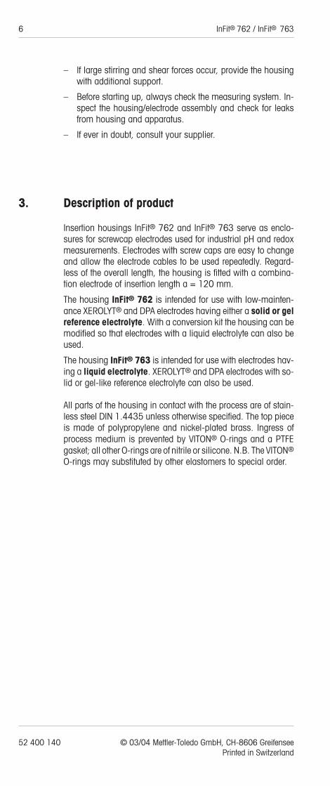
Insertion housings InFit® 762 and InFit® 763 serve as enclo-sures for screwcap electrodes used for industrial pH and redoxmeasurements. Electrodes with screw caps are easy to changeand allow the electrode cables to be used repeatedly. Regard-less of the overall length, the housing is fitted with a combina-tion electrode of insertion length a = 120 mm.
The housing InFit® 762 is intended for use with low-mainten-ance XEROLYT® and DPA electrodes having either a solid or gelreference electrolyte. With a conversion kit the housing can bemodified so that electrodes with a liquid electrolyte can also beused.
The housing InFit® 763 is intended for use with electrodes hav-ing a liquid electrolyte. XEROLYT® and DPA electrodes with so-lid or gel-like reference electrolyte can also be used.
All parts of the housing in contact with the process are of stain-less steel DIN 1.4435 unless otherwise specified. The top pieceis made of polypropylene and nickel-plated brass. Ingress ofprocess medium is prevented by VITON® O-rings and a PTFEgasket; all other O-rings are of nitrile or silicone. N.B. The VITON®
O-rings may substituted by other elastomers to special order.
52 400 140 © 03/04 Mettler-Toledo GmbH, CH-8606 Greifensee Printed in Switzerland

4. Installation and start up procedures
4.1 Installation
When installing the housing, please follow the instructions givenbelow.
4.1.1 Mounting in reactors
The housing is mounted vertically downwards on the reactor bymeans of a standard flange or a weld-in socket.Note: Long housings in vessels with stirrers must be supportedagainst the reaction forces of the stirrer and the process medium.
Socket connection
Use a weld-in socket of DN 50 and length 60 mm.
When fitting the socket, observe the relevant safety regulati-ons on welding.
Follow the welding instructions supplied with each weld-insocket.When the weld is complete, check the diameter of the bore withan H7 gauge and ream out if necessary.
Flange connection
Connect the housing to a flange as stated in your order. The flan-ge connection on the housing can be changed simply by replac-ing flange “60” and gasket “80” (see 8.3 “Spare parts andaccessories”). When replacing, use a flange with the followingspecifications:
Flange standard DIN (ANSI/BS/JIS)
Standard size DN 50/80/100 (2"/3"/4")
Nominal pressure PN 6/10/16
Use only undamaged seals and clean the sealing surfaces be-fore fitting.
InFit® 762 / InFit® 763 7
© 03/04 Mettler-Toledo GmbH, CH-8606 Greifensee 52 400 140Printed in Switzerland
8 InFit® 762 / InFit® 763
4.1.2 Installing and removing the housing
Installing
1. Clean the sealing surfaces.
2. Insert the housing in the flange/weld-in socket provided
3. Tighten the screws/ring nut.
Removing
Before removing the housing, ensure that the process facili-ty is in a safe condition (release pressure, empty, rinse, vent,purge, etc.).
1. Remove the screws from the housing flange or unscrew thering nut from the weld-in socket. Important: With the flanged version, always undo the largeflange screws and never detach the housing by means of thescrews “70” holding the flange (see exploded drawing8.3.1) as this may damage an O-ring while removing thehousing.
2. Draw out the housing.
4.1.3 Installing and removing the electrode
Remove the housing in order to install or remove the electrode.
Removal
1. Applies to InFit® 763 only:The compensation pressure may be reduced by slightly loo-sening the valve or by interrupting and venting the pressuresupply.
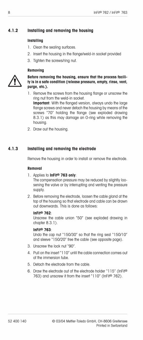
2. Before removing the electrode, loosen the cable gland at thetop of the housing so that electrode and cable can be drawnout downwards. This is done as follows:
InFit® 762:Unscrew the cable union “50” (see exploded drawing inchapter 8.3.1).
InFit® 763:Undo the cap nut “150/30” so that the ring seal “150/10”and sleeve “150/20” free the cable (see opposite page).
3. Unscrew the lock nut “90”.
4. Pull on the insert “110” until the cable connection comes outof the immersion tube.
5. Detach the electrode from the cable.
6. Draw the electrode out of the electrode holder “115” (InFit®763) and unscrew it from the insert “110” (InFit® 762).
52 400 140 © 03/04 Mettler-Toledo GmbH, CH-8606 Greifensee Printed in Switzerland

Installing
Use only clean electrodes. Make sure that sealing surfaces, sealsand O-rings are undamaged and clean.
1. Remove the watering cap from the electrode end and rinsethe end with water.
2. Applies to InFit® 763 only:Remove the elastic band and stopper from the electrolyte fil-ler hole. The elastic band must be taken off completely; theelectrode must not be installed with the elastic band attach-ed.An InFit® 763 with the electrode inside must always be heldvertical so that no electrolyte can escape from the filler hole.
InFit® 762 / InFit® 763 9
© 03/04 Mettler-Toledo GmbH, CH-8606 Greifensee 52 400 140Printed in Switzerland
110
115
110 11090
150/30
150/20
150/10
917630007IG
10 InFit® 762 / InFit® 763
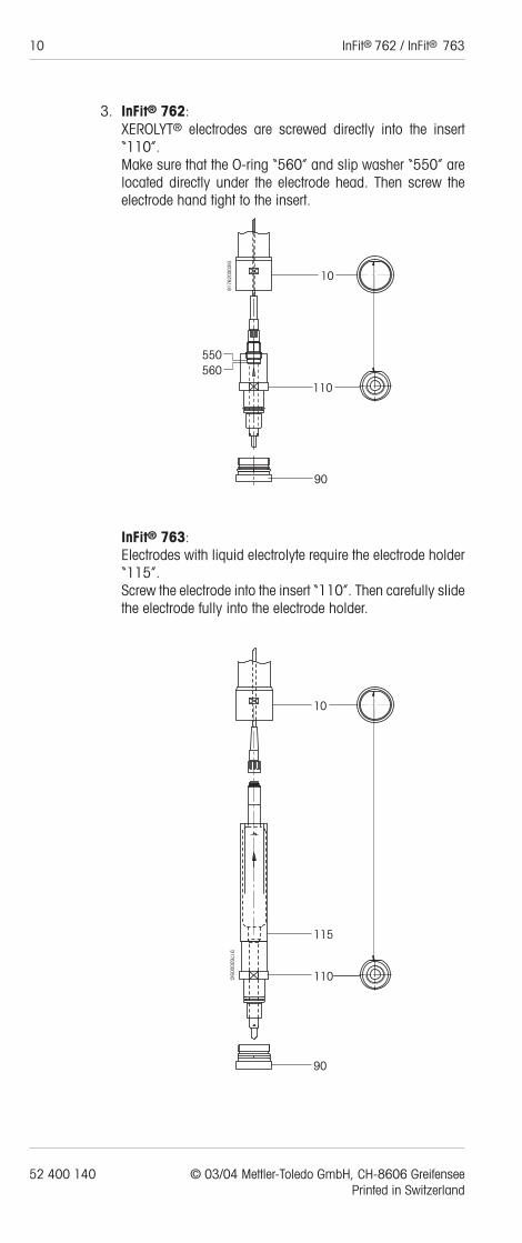
3. InFit® 762:XEROLYT® electrodes are screwed directly into the insert“110”.Make sure that the O-ring “560” and slip washer “550” arelocated directly under the electrode head. Then screw theelectrode hand tight to the insert.
InFit® 763:Electrodes with liquid electrolyte require the electrode holder“115”.Screw the electrode into the insert “110”. Then carefully slidethe electrode fully into the electrode holder.
52 400 140 © 03/04 Mettler-Toledo GmbH, CH-8606 Greifensee Printed in Switzerland
10
110
9176
2000
3IG
560550
90
917630005IG
90
115
110
10
4. Connect the electrode to the cable plug.
5. Slide the insert with the electrode fully into the immersion tube“10”.
6. Pull the cable through at the housing head.
7. Turn the insert until it is fully in place and will no longer turn.Then secure it with the lock nut “90” till hand tight.Note: The lock nut “90” cannot be fastened unless the insert“110” is fully pushed in to the correct position!
8. InFit® 762:Now tighten the cable gland “50”.
InFit® 763:Now tighten the cap nut “150/30”.
Details on connecting the cable to the pH/redox transmitter areto be found in the operating instructions for the pH/mV trans-mitter.
4.1.4 Attaching the cable
InFit® 762:
1. Undo the ring nut “160” and remove the top piece of thehousing.
2. Push the free ends of the cable up through the cap “20” andthe cable gland “50” (see exploded drawing 8.3.1).
3. Then reassemble the top piece.
InFit® 763:
1. Undo the ring nut “160” and remove the top part of the hous-ing.
2. Push the free ends of the cable up through the top piece (seeexploded drawing 8.3.2).
3. Then reassemble the top piece.
Notes:
– Use cable ST-Koax5 for process temperatures below 80 °C.
– Use cable HT-Koax5 for process temperatures above 80 °C.
4.1.5 Checking for correct installation
Each time before starting up, check the measuring system.Inspect the electrode assembly and examine for leaks fromhousing and apparatus (see also section 7).
Do not begin operation until the measuring system has beenchecked and any necessary corrective action taken.
InFit® 762 / InFit® 763 11
© 03/04 Mettler-Toledo GmbH, CH-8606 Greifensee 52 400 140Printed in Switzerland

12 InFit® 762 / InFit® 763
4.2 Start up
4.2.1 Calibrating the electrode assembly
Remove the electrode (see 4.1.3 “Installing and removing theelectrode”).
Details of the calibration procedure are given in the operatinginstructions for the electrode and the pH/mV transmitter.
After installing the assembly, check it for leaks (see also sec-tion 7).
4.2.2 Pressure compensation (InFit® 763 only)
Pressure compensation is necessary only if you use an electro-de with liquid electrolyte. You may skip this section if you use aXEROLYT® electrode with solid electrolyte or a pressurized gelelectrode.
The pressure in the reference electrode must always be hig-her (by 0.2 to 2 bar) than that of the medium (pressure instirrer vessel) to ensure an outward flow of electrolyte.Remember that the hydrostatic pressure of the medium must betaken into account.The compensating pressure for the reference electrode is provid-ed by the air pump or some other oil and dust-free pressure sour-ce. If the latter is chosen, replace the valve assembly with thepressure connector assembly provided. The pressure can beread from the gauge.
If the air pump is used for this purpose, the pressure must befrequently checked and adjusted.
The compensation pressure may be reduced by slightly loosen-ing the valve assembly or by interrupting and venting the pres-sure supply.
5. Routine operation
Applies to InFit® 763 only:In the case of electrodes with liquid electrolyte, the store of elec-trolyte diminishes steadily as it flows out through the diaphragm.The level must therefore be checked regularly.Top up the electrolyte when the level falls close to the bottom ofthe reservoir bulb. To do this, remove the housing and electro-de (see 4.1.2 “Installing and removing the housing” and 4.1.3“Installing and removing the electrode”).
For further details on routine use of the electrode, consult theelectrode operating instructions.
Details on using the pH/mV transmitter are contained in the ope-rating instructions for the transmitter.
52 400 140 © 03/04 Mettler-Toledo GmbH, CH-8606 Greifensee Printed in Switzerland
6. Maintenance
The electrode and housing must be kept clean.Replace any damaged seals or components of the housing.
The insertion housing can be sterilized in situ with the electrodeinstalled.Autoclaving or otherwise heating the complete assembly isnot possible.
Details on maintenance of the electrode are contained in the elec-trode operating instructions.
7. Trouble-shooting
Applies to InFit® 763 only:A defective or poorly installed housing will leak. Testing for leaksis done with the electrode in place. For this, set the pressure inthe housing to 6 bar, using the air pump. A leakproof housingloses less than 0.5 bar in 10 hours.
Test the tightness of the flange joints in the same way as theother flange joints on your reactor.To check the seal between socket and housing, the reactor mustbe air-pressurized. Any air escaping can be detected with an air-detecting spray.A leaky connection can be cured by cleaning the sealing surfa-ces and lubricating the seals with a silicone-free grease. Faultyseals must be replaced.Caution! Do not do anything to the housing before the pres-sure in the piping and housing has been released again.
Damaged or faulty parts of the housing must be replaced forsafety reasons.
InFit® 762 / InFit® 763 13
© 03/04 Mettler-Toledo GmbH, CH-8606 Greifensee 52 400 140Printed in Switzerland
14 InFit® 762 / InFit® 763
8. Specifications
8.1 Delivery
A standard delivery comprises the following items:
InFit® 763:
– Housing InFit® 763
– Bicycle pump
– Instruction manual
– Electrolyte top-up syringe
– Pressure connector assembly
InFit® 762:
– Housing InFit® 762
– Instruction manual
Conversion kit InFit® 762 to InFit® 763:
– Top piece complete with pressure gauge 0 to 6 bar
– Electrode holder
– Bicycle pump
– Electrolyte top-up syringe
– Pressure connector assembly
52 400 140 © 03/04 Mettler-Toledo GmbH, CH-8606 Greifensee Printed in Switzerland

8.2 Technical specification
Environmental condition
temperature range - 30…80 °C
Process conditions
temperature range [TS] -30…140 °C
Max. pressure [PS] 6 bar working pressuredepending on typ of sensor [PS] 0…6 bar
Connections
Flange:
Flange standard DIN (ANSI/BS/JIS)
Standard size DN 50/80/100 (2"/3"/4")
Nominal pressure PN 6/10/16
Weld-in socket:
Diameter ø50-H7
Thread R 2"
Length 60 mm
Materials (standard version)
Top piece Nickel-plated brass, polypropylene
Wetted parts Stainless steel DIN 1.4404, Surface roughness <1.6µm,VITON® O-ringsPTFE gasket plate
Special versions see 8.3.1/8.3.2
Dimensions see Appendix A and B
Pressure information
ccording to PED-Article 1, Section. 2.2,:«Pressure» is referen-ced to atmospheric pressure, e.g. an overpressure. Accor-dingly, a pressure in the vacuum region will be expressed as a negative pressure.
InFit® 762 / InFit® 763 15
© 03/04 Mettler-Toledo GmbH, CH-8606 Greifensee 52 400 140Printed in Switzerland
16 InFit® 762 / InFit® 763
52 400 140 © 03/04 Mettler-Toledo GmbH, CH-8606 Greifensee Printed in Switzerland
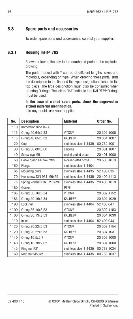
8.3 Spare parts and accessories
To order spare parts and accessories, contact your supplier.
8.3.1 Housing InFit® 762
Shown below is the key to the numbered parts in the explodeddrawing.
The parts marked with * can be of different lengths, sizes andmaterials, depending on type. When ordering these parts, statethe description in the list and the type designation etched in thetop piece. The type designation must also be consulted whenordering O-rings. The letters “KA” indicate that KALREZ® O-ringsmust be used.
In the case of wetted spare parts, check the engraved oretched material identification.If in any doubt, ask your supplier.
No. Description Material Order No.* 10 Immersion tube H= x
* 15 O-ring 40.64x5.33 VITON® 20 302 1008
* 15 O-ring 40.65x5.33 KALREZ® 20 304 1007
20 Cap stainless steel 1.4435 00 762 1001
30 O-ring 30.80x3.60 silicone 20 301 1007
40 Screw eye M8 nickel-plated brass 20 401 1000
50 Cable gland PG7/4-7/MS nickel-plated brass 20 503 1013
* 60 Flange stainless steel 1.4404
65 Mounting plate stainless steel 1.4435 52 400 035
70 Hex screw DIN 931-M6x25 stainless steel 1.4435 20 400 1113
75 Spring washer DIN 127B-M6 stainless steel 1.4435 20 400 1019
* 80 Gasket PTFE
* 85 O-ring 50.16x5.34 VITON® 20 302 1152
* 85 O-ring 50.16x5.34 KALREZ® 20 304 1029
* 90 Lock nut stainless steel 1.4404 52 400 047
* 100 O-ring 36.10x3.53 VITON® 20 302 1153
* 100 O-ring 36.13x3.53 KALREZ® 20 304 1030
110 Insert stainless steel 1.4404 52 400 044
* 120 O-ring 20.22x3.53 VITON® 20 302 1154
* 120 O-ring 20.22x3.53 KALREZ® 20 304 1031
* 140 O-ring 10.5x2.7 VITON® 20 302 1000
* 140 O-ring 10.78x2.62 KALREZ® 20 304 1000
145 Ring nut R2" stainless steel 1.4435 00 763 1034
160 Ring nut M50x2 stainless steel 1.4435 00 763 1037
InFit® 762 / InFit® 763 17
© 03/04 Mettler-Toledo GmbH, CH-8606 Greifensee 52 400 140Printed in Switzerland
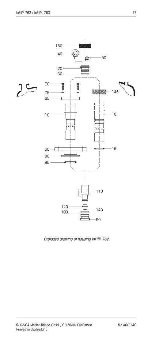
Exploded drawing of housing InFit® 762
145
10
15
110
917620002
140
90
100120
85
80
60
10
6575
70
50
160
40
2030
18 InFit® 762 / InFit® 763
52 400 140 © 03/04 Mettler-Toledo GmbH, CH-8606 Greifensee Printed in Switzerland
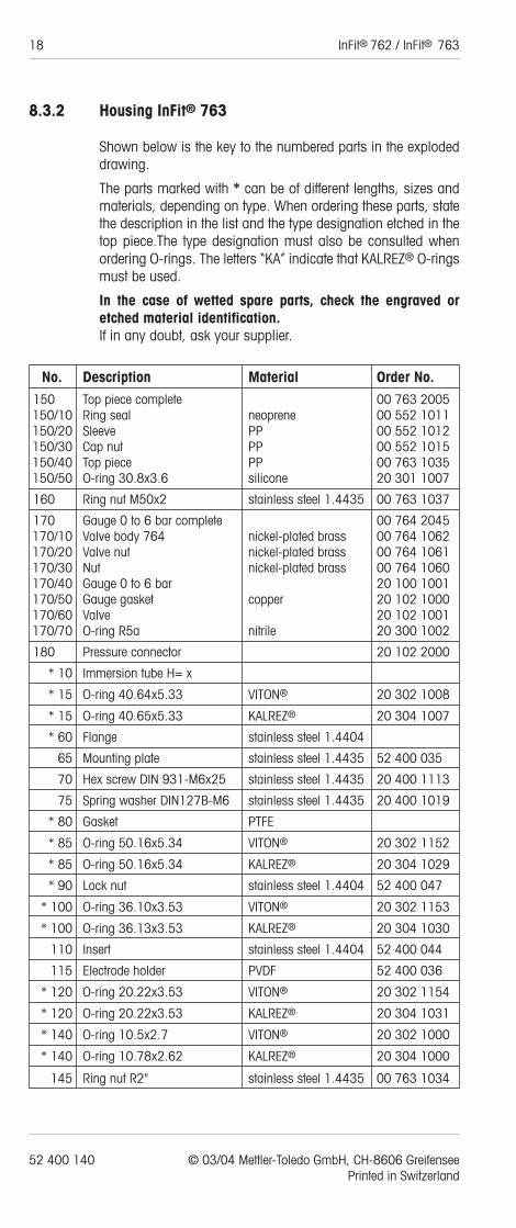
8.3.2 Housing InFit® 763
Shown below is the key to the numbered parts in the explodeddrawing.
The parts marked with * can be of different lengths, sizes andmaterials, depending on type. When ordering these parts, statethe description in the list and the type designation etched in thetop piece.The type designation must also be consulted whenordering O-rings. The letters “KA” indicate that KALREZ® O-ringsmust be used.
In the case of wetted spare parts, check the engraved oretched material identification.If in any doubt, ask your supplier.
No. Description Material Order No.150 Top piece complete 00 763 2005150/10 Ring seal neoprene 00 552 1011150/20 Sleeve PP 00 552 1012150/30 Cap nut PP 00 552 1015150/40 Top piece PP 00 763 1035150/50 O-ring 30.8x3.6 silicone 20 301 1007
160 Ring nut M50x2 stainless steel 1.4435 00 763 1037
170 Gauge 0 to 6 bar complete 00 764 2045170/10 Valve body 764 nickel-plated brass 00 764 1062170/20 Valve nut nickel-plated brass 00 764 1061170/30 Nut nickel-plated brass 00 764 1060170/40 Gauge 0 to 6 bar 20 100 1001170/50 Gauge gasket copper 20 102 1000170/60 Valve 20 102 1001170/70 O-ring R5a nitrile 20 300 1002
180 Pressure connector 20 102 2000
* 10 Immersion tube H= x
* 15 O-ring 40.64x5.33 VITON® 20 302 1008
* 15 O-ring 40.65x5.33 KALREZ® 20 304 1007
* 60 Flange stainless steel 1.4404
65 Mounting plate stainless steel 1.4435 52 400 035
70 Hex screw DIN 931-M6x25 stainless steel 1.4435 20 400 1113
75 Spring washer DIN127B-M6 stainless steel 1.4435 20 400 1019
* 80 Gasket PTFE
* 85 O-ring 50.16x5.34 VITON® 20 302 1152
* 85 O-ring 50.16x5.34 KALREZ® 20 304 1029
* 90 Lock nut stainless steel 1.4404 52 400 047
* 100 O-ring 36.10x3.53 VITON® 20 302 1153
* 100 O-ring 36.13x3.53 KALREZ® 20 304 1030
110 Insert stainless steel 1.4404 52 400 044
115 Electrode holder PVDF 52 400 036
* 120 O-ring 20.22x3.53 VITON® 20 302 1154
* 120 O-ring 20.22x3.53 KALREZ® 20 304 1031
* 140 O-ring 10.5x2.7 VITON® 20 302 1000
* 140 O-ring 10.78x2.62 KALREZ® 20 304 1000
145 Ring nut R2" stainless steel 1.4435 00 763 1034
InFit® 762 / InFit® 763 19
© 03/04 Mettler-Toledo GmbH, CH-8606 Greifensee 52 400 140Printed in Switzerland
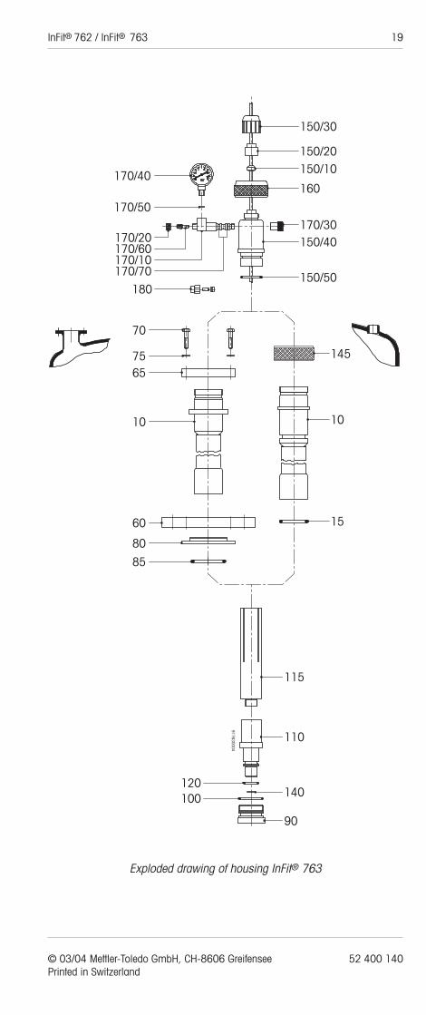
Exploded drawing of housing InFit® 763
150/30
150/20150/10
160
170/30150/40
150/50
145
10
15
115
110
917630004
140
90
100120
85
80
60
10
6575
70
180
170/70170/10170/60170/20
170/50
170/40
20 InFit® 762 / InFit® 763
52 400 140 © 03/04 Mettler-Toledo GmbH, CH-8606 Greifensee Printed in Switzerland
8.3.3 Converting from InFit® 762 to InFit® 763
The InFit® 762 housing can be converted for use with electro-des containing liquid electrolyte. For this purpose, order the con-version kit (see 8.3.5 “Accessories”). To convert:
1. Remove the housing and electrode as described in 4.1.2 and4.1.3.
2. Detach the cable as described in 4.1.4.
3. Take off the top piece of the InFit® 762 housing (20, 30, 40,50 and 160, see exploded drawing 8.3.1) and then
4. Fit the new top piece (see exploded drawing 8.3.2).
With this conversion you now have an InFit® 763 housing. Fol-low the instructions regarding operation and maintenance ofhousing InFit® 763.
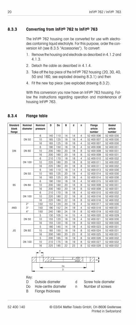
8.3.4 Flange table
Standard Nominal Nominal D Do B d n Flange Gasketblank diameter pressure article articleflange number number
6 140 110 14 14 4 52 400 006 52 400 030DN 50 10 165 125 18 18 4 52 400 007 52 400 030
16 165 125 18 18 4 52 400 007 52 400 0306 190 150 16 18 4 52 400 008 52 400 031
DIN DN 80 10 200 160 20 18 8 52 400 009 52 400 03116 200 160 20 18 8 52 400 009 52 400 0316 210 170 18 18 4 52 400 010 52 400 032
DN 100 10 220 180 20 18 8 52 400 011 52 400 03216 220 180 20 18 8 52 400 011 52 400 0326 140 110 16 14 4 52 400 013 52 400 030
DN 50 10 165 125 20 18 4 52 400 014 52 400 03016 165 125 20 18 4 52 400 014 52 400 0306 190 150 18 18 4 52 400 015 52 400 031
BS DN 80 10 200 160 20 18 8 52 400 009 52 400 03116 200 160 20 18 8 52 400 009 52 400 0316 210 170 18 18 4 52 400 010 52 400 032
DN 100 10 220 180 22 18 8 52 400 016 52 400 03216 220 180 22 18 8 52 400 016 52 400 032
2" 150 152 120 20 19 4 52 400 017 52 400 030ANSI 3" 150 190 152 24 19 4 52 400 018 52 400 031
4" 150 240 190 24 19 8 52 400 019 52 400 0325 130 105 14 15 4 52 400 020 52 400 029
DN 50 10 155 120 16 19 4 52 400 021 52 400 03016 155 120 16 19 8 52 400 022 52 400 0305 180 145 14 19 4 52 400 023 52 400 031
JIS DN 80 10 185 150 18 19 8 52 400 024 52 400 03116 200 160 20 23 8 52 400 025 52 400 0315 200 165 16 19 8 52 400 026 52 400 032
DN 100 10 210 175 18 19 8 52 400 027 52 400 03216 225 185 22 23 8 52 400 028 52 400 032
Key:D Outside diameter d Screw hole diameterDo Hole-centre diameter n Number of screwsB Flange thickness
Do
D
B
d
n

InFit® 762 / InFit® 763 21
© 03/04 Mettler-Toledo GmbH, CH-8606 Greifensee 52 400 140Printed in Switzerland
8.3.5 Accessories
Description Order No.
Cable AS9/HT-Koax 5Temperature range -30 to 130 °C
3 m 10 001 03155 m 10 001 0515
10 m 10 001 1015
Cable AS9/ST-Koax 5Temperature range -30 to 80 °C
3 m 10 001 03025 m 10 001 0502
10 m 10 001 1002
Weld-in socket L = 60 mm1.4435 stainless steel 00 763 10381.4571 stainless steel 00 763 1144HASTELLOY® -C22 00 763 1299
Blind plugFor closing off the weld-in socket 00 763 20001.4435 stainless steel
Protective cage1.4404 stainless steel 00 764 10461.4571 stainless steel 00 764 1210HASTELLOY® -C22 00 764 1328
ø 68ø 50 H7
G2"
60 2240
40
2235
ø 24
55
2230
B
22 InFit® 762 / InFit® 763
52 400 140 © 03/04 Mettler-Toledo GmbH, CH-8606 Greifensee Printed in Switzerland
Description Order No.
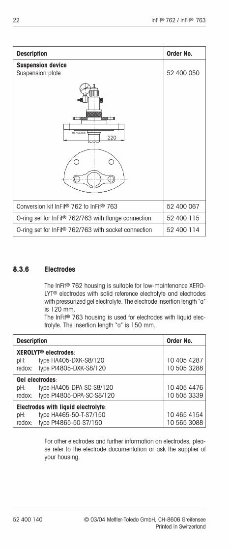
Suspension deviceSuspension plate 52 400 050
Conversion kit InFit® 762 to InFit® 763 52 400 067
O-ring set for InFit® 762/763 with flange connection 52 400 115
O-ring set for InFit® 762/763 with socket connection 52 400 114
8.3.6 Electrodes
The InFit® 762 housing is suitable for low-maintenance XERO-LYT® electrodes with solid reference electrolyte and electrodeswith pressurized gel electrolyte. The electrode insertion length “a”is 120 mm.The InFit® 763 housing is used for electrodes with liquid elec-trolyte. The insertion length “a” is 150 mm.
Description Order No.
XEROLYT® electrodes:pH: type HA405-DXK-S8/120 10 405 4287redox: type Pt4805-DXK-S8/120 10 505 3288
Gel electrodes:pH: type HA405-DPA-SC-S8/120 10 405 4476redox: type Pt4805-DPA-SC-S8/120 10 505 3339
Electrodes with liquid electrolyte:pH: type HA465-50-T-S7/150 10 465 4154redox: type Pt4865-50-S7/150 10 565 3088
For other electrodes and further information on electrodes, plea-se refer to the electrode documentation or ask the supplier ofyour housing.
220917630006

InFit® 762 / InFit® 763 23
© 03/04 Mettler-Toledo GmbH, CH-8606 Greifensee 52 400 140Printed in Switzerland
8.4 Warranty
The housings are of high technical quality and undergo a policyof continuous design review to incorporate the latest advances.Their reliability is ensured by a thorough final inspection prior toleaving our factory.
The warranty is valid for one year from the date of delivery andcovers any defects due to faulty materials or manufacture.
Not covered by the warranty are normal wear and tear and anydamage caused by improper use (e.g. chemical incompatibili-ty of the materials, etc.).
The warranty extends only to replacement or repair of deficientproducts, at our discretion.
The warranty is void if the customer or others modify in any waythe products supplied by us. Defects must be reported to the sup-plier immediately upon discovery, and in all events within thewarranty period.
24 InFit® 762 / InFit® 763
52 400 140 © 03/04 Mettler-Toledo GmbH, CH-8606 Greifensee Printed in Switzerland
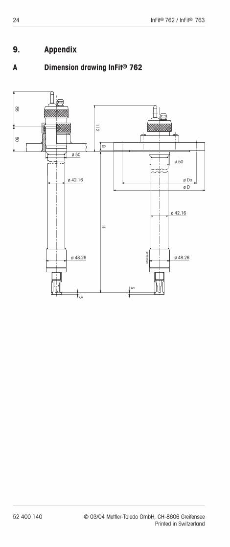
9. Appendix
A Dimension drawing InFit® 762
ø 48.26
917620001
5
ø 42.16
ø D
ø Do
ø 50
HB
112
5
ø 48.26
ø 42.16
ø 50
6086

InFit® 762 / InFit® 763 25
© 03/04 Mettler-Toledo GmbH, CH-8606 Greifensee 52 400 140Printed in Switzerland
B Dimension drawing InFit® 763
ø 48.26
917630003
5
ø 42.16
ø D
ø Do
ø 50
HB
5
ø 48.26
ø 42.16
ø 50
60130
156

BR Mettler-Toledo Ind. e Com. Ltda., Alameda Araguaia, 451 - Alphaville,BR – 06455-000 Barueri / SP, BrazilPhone +55 11 4166 74 00, Fax +55 11 4166 74 01
CH Mettler-Toledo (Schweiz) AG, Im Langacher, CH – 8606 Greifensee, SwitzerlandPhone +41 44 944 45 45, Fax +41 44 944 45 10
D Mettler-Toledo GmbH, Prozeßanalytik, Ockerweg 3, D – 35396 Gießen, GermanyPhone +49 641 507-333, Fax +49 641 507-397
F Mettler-Toledo Analyse Industrielle Sàrl, 30 Bld. de Douaumont, BP 949,F – 75829 Paris Cedex 17, FrancePhone +33 1 47 37 0600, Fax +33 1 47 37 4626
USA Mettler-Toledo Ingold, Inc., 36 Middlesex Turnpike, Bedford, MA 01730, USAPhone +1 781 301-8800, Toll free +1 800 352-8763, Fax+1 781 271-0681
Mettler-Toledo GmbH, Process Analytics, Industrie Nord, CH-8902 Urdorf,Tel. +41 44 736 22 11, Fax +41 44 736 26 36Subject to technical changes. 03/04. © Mettler-Toledo GmbH. Printed in Switzerland. 52 400 140