influence of deflection hole angle on … · influence of deflection hole angle on effusion cooling...
TRANSCRIPT
INFLUENCE OF DEFLECTION HOLE ANGLE ON EFFUSION
COOLING IN A REAL COMBUSTION CHAMBER CONDITION
by
Xiao LIU * and Hongtao ZHENG
College of Power and Energy Engineering, Harbin Engineering University, Harbin, China
Original scientific paperDOI: 10.2298/TSCI140107043L
Fluid-solid coupling simulation is conducted to investigate the performance of effu-sion cooling in the real combustion chamber condition of strong rotation and pri-mary holes. The wall temperature and film cooling effectiveness of different deflec-tion angle is analyzed. From the results, it is concluded that the performance ofeffusion is better than conventional film cooling. The wall temperature and gradi-ent is lower, the cooling efficiency is higher and the coolant is reduced by 20%, butpressure loss is slightly increased. The cooling effectiveness decreases behind pri-mary holes because of local combustion. Comparison with the effect of deflectionangle, the cooling performance of 60 deg deflection angle is best. The coolant isbetter attached to the wall downstream when the deflection angle is same as the ro-tating mainstream. In addition, the effect of deflection angle is not so significant onthe coolant flow rate, but a large negative impact on the pressure loss. Although thecooling effectiveness of 60 deg deflection angle is highest, the total pressure recov-ery coefficient is lower. The maximum temperature drops about 70 K and the outlettemperature distribution trends more consistent. So various factors should be takeninto consideration when designing of deflection angle.
Key words: combustor, effusion cooling, deflection angle, cooling effectiveness,CFD simulation
Introduction
High temperature rise of combustion chamber is required for the development of mod-
ern aero-engines. This trend results in coolant flow rate reduction used for protecting combustor
liner wall, so the requirement of combustion and cooling air forms a contradiction. There is an
urgent need to adopt high temperature resistant alloy material or an efficient combustor liner
cooling technology. As the development pace of high-temperature materials cannot meet the
needs of aviation engine technology, so the cooling technology is playing an increasingly signif-
icant role in advanced aero-engines.
Today four main cooling systems are implemented to preserve the liner performance:
general film cooling, transpiration, effusion and impingement cooling [1], and the importance of
the cooling has been given more attention. Li et al. [2] conducted investigations to understand
the characteristics of the flow, combustion, cooling performance and their interaction in an
aero-engine combustor by fluid-solid coupling simulation. Ali et al. [3] elucidated the effective-
Liu, X., et al.: Influence of Deflection Hole Angle on Effusion Cooling in a ...THERMAL SCIENCE: Year 2015, Vol. 19, No. 2, pp. 645-656 645
* Corresponding author; e-mail: [email protected]
ness of a cooling system in the protection of combustor walls by numerical simulations in a gas
turbine swirl stabilized combustor. Yu et al. [4] presented the relationship between the angles of
the hole, the orientations of the flow injection and the film-cooling effectiveness in the transition
piece of combustor. The effusion cooling is regarded as one between the general film and tran-
spiration cooling technology, and an effusion cooling system consists of three cooling pro-
cesses: convection cooling on cold-side, the cooling effect inside the inclined holes and film
cooling on hot-side wall surface. Both numerical and experimental investigations on effusion
film cooling have been conducted by many researchers. Andrews et al. [5-7] studied the influ-
ence of cooling hole size, pitch, and inclination angle through a number of experiments. Experi-
mental and numerical investigations were performed on the overall cooling effectiveness by Lin
[8-10]. The test plates had different hole-spacing, different deflection angle, and different incli-
nation angle, and it was mainly focused on studying the influence of hole geometrical parame-
ters and blowing ratio on film cooling. Scrittore et al. [11,12] measured velocity profiles and di-
lution hole injection effect on effusion behavior. They found that blowing ratios had a very low
effect of blowing ratio on cooling performance, the dilution hole injection leaded to an increased
spreading of coolant jets. Goldstein [13] studied the film cooling performance downstream of
one row of holes with 35 deg inclination angle, 45 deg compound angle, and 3d hole spacing.
Ling et al. [14] obtained the film cooling effectiveness and heat transfer coefficient in a full cov-
erage film cooling wall with different hole-spacing of 16d to 10d, using the transient liquid crys-
tal technique. Gustafsson et al. [15] investigated the temperature distribution on effusion-cooled
plates with different parameters of temperature ratios, velocity ratios, injection hole-spacing, in-
clination angle, and thermal conductivity of the test plates. Yang et al. [16] investigated the evo-
lution of the film by many multi-hole arrangements at several blowing ratios. Harrington et al.
[17] studied the effect of the mainstream turbulence on the adiabatic effectiveness of
large-scaled full coverage film cooling plates. Facchini et al. [18] investigated the influence of a
re-circulation area in the mainstream. They obtained that the presence of the re-circulation
leaded to a general reduction of effectiveness.
From the open literatures of effusion cooling, it is found that most of the research re-
sults were obtained from the simplified model (flat plate, uniform hot mainstream and coolant
air). There are big differences in the cooling structure and air-inlet condition between the model
and real combustion chamber, which will have a huge impact on the flow and heat transfer char-
acteristics: (1) the big holes (primary and dilution hole) exist in the combustion chamber and (2)
there is a strong tangential velocity with the effect of swirler. But it generally ignored those ef-
fects in the simplified model. So the current work employed fluid-solid coupling simulation by
FLUENT 12.0 to study the wall temperature and film cooling effectiveness of different deflec-
tion angle on the real combustion chamber condition.
Model description
The governing equations are solved using CFD package ANSYS FLUENT 12.0. The
SIMPLE method was used for velocity-pressure coupling. A second-order discretization
scheme was used to solve all governing equations. This paper adopted Euler method to calculate
gas flow and Lagrange method to calculate discrete phase, when using Lagrange method, time
particle residence time will be solved. In addition, realizable k-e model, probability density
function (PDF) combustion model and radiation model were used to calculate chemical reaction
with turbulence.
Liu, X., et al.: Influence of Deflection Hole Angle on Effusion Cooling in a ...646 THERMAL SCIENCE: Year 2015, Vol. 19, No. 2, pp. 645-656

Turbulence model
As the simplest “complete models” to predict the turbulent combustion reaction, the
realizable model is widely used in swirl turbulent combustion in the past few years [19, 20], it
has been extensively validated for a wide range of flows. The fundamental equations of realiz-
able k-e model are:
( )( ) ( )
rr re -
k
tk k G G Y S� � � � � � � � �
�
V k k b k kG (1)
( )( ) ( )
rer e e r e r
e
ne
ee e e
tC S C
kC
kC Gb� � � � � � �
��
�
V G 1 2
2
1 3 � S e (2)
Combustion model
The hydrocarbon fuel's burning is extremely complex, it is impossible to describe
combustion performance with one particular combustion model, so it is needed to simplify com-
bustion characteristic. At the basic of simple chemical reaction system hypothesis, we ignored
chemical reaction mechanism to calculate combustion flow field. The major researched object is
average-thermal-effect. The fast chemical reaction model which based on simple probability
density function (PDF) has been used to simulate fuel oil burning. To close combustion model-
ing, b function was adopted to describe turbulence fluctuation instantaneous characteristic of
conservation variable mix fraction. The complete chemical reaction equation is:
C H O CO H O212 23 2 2355 12 115� � �. . (3)
Under the assumption of equal diffusivities, the species equations can be reduced to a
single equation for the mixture fraction, f. The reaction source terms in the species equations
cancel (since elements are conserved in chemical reactions), and thus f is a conserved quantity.
While the assumption of equal diffusivities is problematic for laminar flows, it is generally ac-
ceptable for turbulent flows where turbulent convection overwhelms molecular diffusion. The
Favre mean (density-averaged) mixture fraction equation is:
¶tf f f S S( ) ( )r r
m
s� � � � �
�
���
�� � �
�
v t
t
m user (4)
The source term Sm is due solely to transfer of mass into the gas phase from liquid fuel
droplets or reacting particles. Suser is any user-defined source term.
In addition to solving for the Favre mean mixture fraction, ANSYS FLUENT solves a
conservation equation for the mixture fraction variance, �f 2 :
¶tf f f C f C( ) ( ) ( )r r
m
sm� � � � � � � �
�
���
�� � � �2 2 2 2
�
v t
t
g t d re
kf S� �2
user (5)
where � � �f f f . The default values for the constants st, Cg, and Cd are 0.85, 2.86, and 2.0, re-
spectively, and Suser is any user-defined source term.
The probability density function, written as p(f), can be thought of as the fraction of
time that the fluid spends in the vicinity of the state f. The fluctuating value of f, spends some
fraction of time in the range denoted as Df·p(f), takes on values such that the area under its curve
in the band denoted, Df, is equal to the fraction of time that f spends in this range. Written math-
ematically:
Liu, X., et al.: Influence of Deflection Hole Angle on Effusion Cooling in a ...THERMAL SCIENCE: Year 2015, Vol. 19, No. 2, pp. 645-656 647
p f fTT
ii
( ) limD � ��
1t (6)
where T is the time scale and ti – the amount of time that t spends in the Df band. The shape of
the function p(f) depends on the nature of the turbulent fluctuations in f. In practice, p(f ) is un-
known and is modeled as a mathematical function that approximates the actual PDF shapes that
have been observed experimentally.
The probability density function p(f ), describing the temporal fluctuations of f in the
turbulent flow, can be used to compute averaged values of variables that depend on f. Den-
sity-weighted mean species mass fractions and temperature can be computed as
f fi ip f f f� � ( ) ( )d0
1
(7)
Importantly, the PDF shape p(f) is a function of only its first two moments, namely the
mean mixture fraction, f, and the mixture fraction variance, �f 2 . Thus, given ANSYS FLU-
ENT's prediction of f and �f 2 at each point in the flow field (eqs. 4 and 5), the assumed PDF
shape can be computed and used as the weighting function to determine the mean values of spe-
cies mass fractions, density, and temperature.
Radiation model
The discrete ordinate radiation model [21] was used in this work, as it is applicable
across a wide range of optical thicknesses. The model solves the radiative transfer equation
(RTE) for a finite number of discrete solid angles across the computational domain. It also incor-
porates the weighted sum of gray gas model (WSGG), in which spatial variation in the total
emissivity is computed as a function of gas composition and temperature. The WSGG is a rea-
sonable compromise between the oversimplified gray gas model and a complete model, which
takes into account particular absorption bands.
Results and discussion
Meshing and model validation
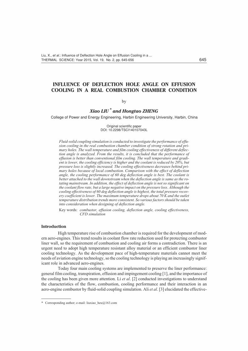
Unstructured tetrahedral meshes wereused for simulation computation by ANSYSICEM CFD. The total mesh number of generalfilm cooling model is 7.0e+06 after grid inde-pendence analysis. Due to refining of multismall holes, the mesh number increases to1.0e+07. Figure 1 shows the tetrahedralmeshes of 2-D view of cross-section forcombustor with effusion cooling. It can beseen that, near the cooling holes, the grid is re-fined, there are at least 10 nodes at each holefor accurate simulation.
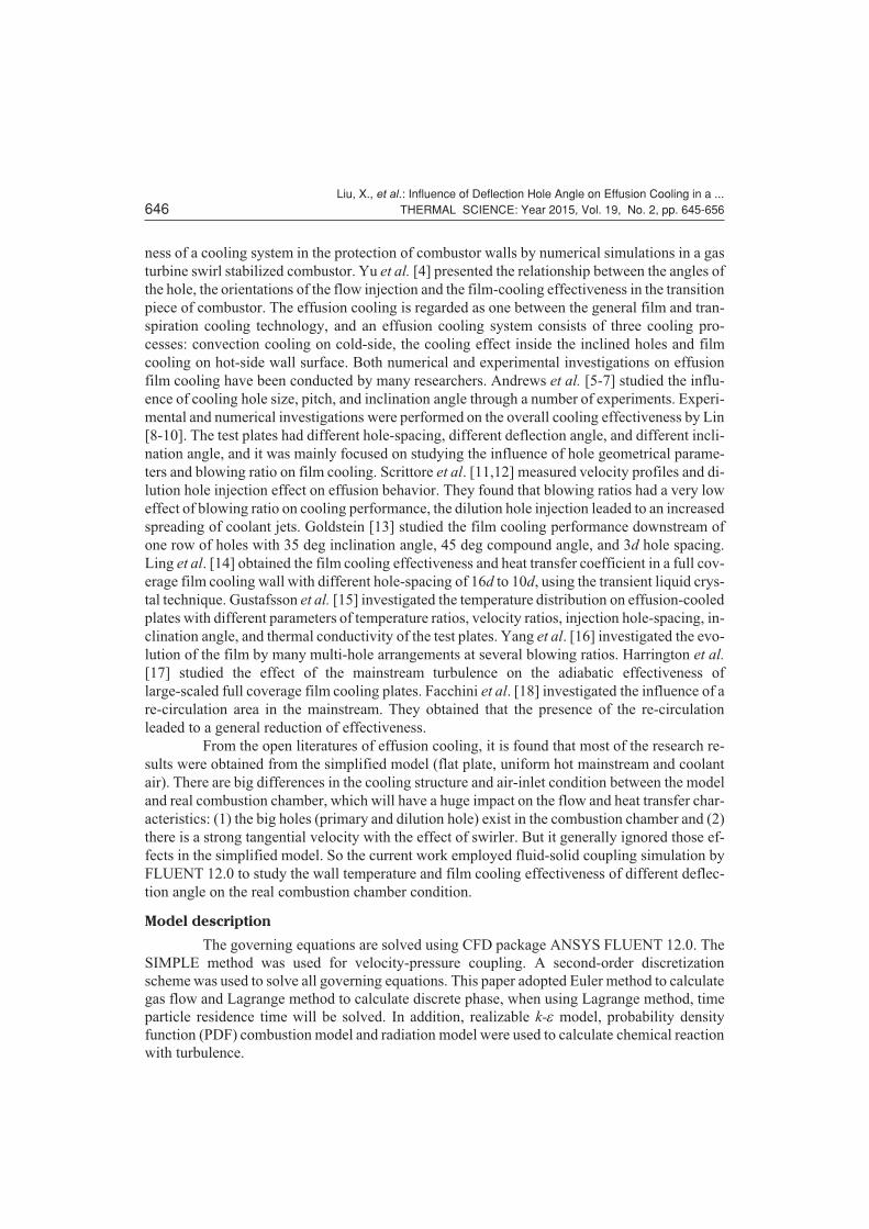
In this paper, the experimental data [22] of an annular combustion chamber was used formodel validation. The infrared imaging technique was used for the non-intrusive surface tempera-ture measurements. Cold (air mass flow 0.24 kg/s, 500 K) and three gas oil ratio (f = 0.01950,0.02600, 0.03308) combustion fields were calculated and compared. The fuel temperature is300 K and operating pressure is 0.13 MPa. Experiment system and the double swirl annularcombustor geometry (1/24) was shown in fig. 2, the detailed description can be found in [22].
Liu, X., et al.: Influence of Deflection Hole Angle on Effusion Cooling in a ...648 THERMAL SCIENCE: Year 2015, Vol. 19, No. 2, pp. 645-656
Figure 1. 2-D view of cross-section for combustorwith effusion cooling (for color image see journalweb-site)
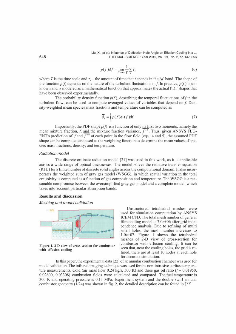
Under the experimental conditions, the combustion flame considered is a turbulent
diffusion flame. Figure 3 shows the streamlines of particle image velocimetry (PIV) experiment
and different turbulence model. A counter-rotating vortex pair (CRVP) can be easily seen,
which ensures the ignition and flame stability formed in the head zone of the combustor. The
predicted streamlines obtained by k-e model are in good agreement with PIV. Vortex pitch is so
accurate, shoving that simulation of strong rotational flow is pretty well.
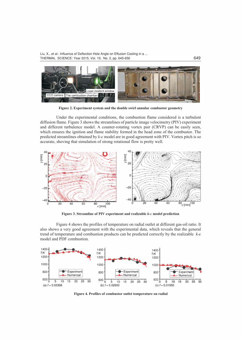
Figure 4 shows the profiles of temperature on radial outlet at different gas-oil ratio. It
also shows a very good agreement with the experimental data, which reveals that the general
trend of temperature and combustion products can be predicted correctly by the realizable k-e
model and PDF combustion.
Liu, X., et al.: Influence of Deflection Hole Angle on Effusion Cooling in a ...THERMAL SCIENCE: Year 2015, Vol. 19, No. 2, pp. 645-656 649
Figure 2. Experiment system and the double swirl annular combustor geometry
Figure 3. Streamline of PIV experiment and realizable k-e model prediction
Figure 4. Profiles of combustor outlet temperature on radial
The prototype combustor liner is cooled by the full film from discrete tiny holes with
the average diameter 2 mm. The temperature dependences of the thermal conductivity (ls) and
the specific heat capacity (Cs) of the solid material were incorporated using polynomial func-
tions, shown in formula (8) and (9):
ls T T T� � � � � �� �9946 0018 1489 10 1364 105 2 8 3. . . . (8)
C T T Ts � � � � � �� �411222 0293 2 412 10 1507 104 2 7 3. . . . (9)
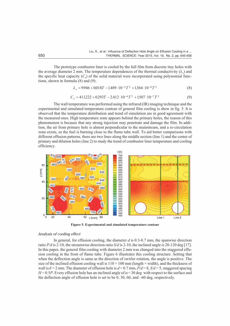
The wall temperature was performed using the infrared (IR) imaging technique and the
experimental and simulated temperature contour of general film cooling is show in fig. 5. It is
observed that the temperature distribution and trend of simulation are in good agreement with
the measured ones. High temperature zone appears behind the primary holes, the reason of this
phenomenon is because that any strong injection may penetrate and damage the film. In addi-
tion, the air from primary hole is almost perpendicular to the mainstream, and a re-circulation
zone exists, so the fuel is burning close to the flame tube wall. To aid better comparisons with
different effusion patterns, there are two lines along the middle section (line 1) and the center of
primary and dilution holes (line 2) to study the trend of combustor liner temperature and cooling
efficiency.
Analysis of cooling effect
In general, for effusion cooling, the diameter d is 0.3-0.7 mm, the spanwise direction
ratio P/d is 2-10, the streamwise direction ratio S/d is 2-10, the inclined angle is 20-120 deg [17].
In this paper, the general film cooling with diameter 2 mm was changed into the staggered effu-
sion cooling in the front of flame tube. Figure 6 illustrates this cooling structure. Setting that
when the deflection angle is same as the direction of swirler rotation, the angle is positive. The
size of the inclined effusion cooling wall is 110 × 100 mm (length × width), and the thickness of
wall is d = 2 mm. The diameter of effusion hole is d = 0.7 mm, P/d = 8, S/d = 5, staggered spacing
H = 0.5P. Every effusion hole has an inclined angle of a= 30 deg with respect to the surface and
the deflection angle of effusion hole is set to be 0, 30, 60, and –60 deg, respectively.
Liu, X., et al.: Influence of Deflection Hole Angle on Effusion Cooling in a ...650 THERMAL SCIENCE: Year 2015, Vol. 19, No. 2, pp. 645-656
Figure 5. Experimental and simulated temperature contour

Figure 7 shows the temperature distribu-
tion of different deflection angles, respectively.
For general film cooling, the cold air from film
cooling hole will form a film layer to protect the
wall on hot-side. The temperature near down-
stream of the cooling hole is low, however, the
cooling capacity declines with the increase of
distance. There is a local high temperature zone
behind the primary hole and it will reduce the
service life of the flame tube. For the effusion
cooling, the temperature distribution becomes
more uniform. The cooling performance of
60 deg is better than others and the –60 deg is the worst. There is a large temperature gradient be-
hind the primary holes along the axial direction for 0 and –60 deg, but it is still better than the ef-
fect of general film cooling, which means the good cooling performance of combustor liner us-
ing effusion cooling technology.
In addition, the trends of temperature along two lines are shown in fig. 8. It is easily
seen that the temperature at the starting of the wall is low as air inlet, then it starts to rise rapidly
after the primary hole. The 60 deg hole angle model has the best effect, only consider the wall
temperature distribution. According to the conclusion of Gustafsson et al. [15], the arrangement
of the holes should be more dense to protect the behind primary holes where is the easiest sec-
tion of high temperature.
Liu, X., et al.: Influence of Deflection Hole Angle on Effusion Cooling in a ...THERMAL SCIENCE: Year 2015, Vol. 19, No. 2, pp. 645-656 651
Figure 6. Structure of effusion cooling
Figure 7. Temperature distribution of different deflection angles
Figure 8. Temperature along two lines
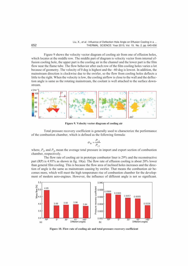
Figure 9 shows the velocity vector diagram of cooling air from one of effusion holes,
which locates at the middle row. The middle part of diagram is velocity vector from internal ef-
fusion cooling hole, the upper part is the cooling air in the channel and the lower part is the film
flow near the flame tube. The flow behavior after each row of the film cooling holes varies a lot
because of geometry. The velocity of 0 deg is highest and the –60 deg is lowest. In addition, the
mainstream direction is clockwise due to the swirler, so the flow from cooling holes deflects a
little to the right. When the velocity is low, the cooling airflow is close to the wall and the deflec-
tion angle is same as the rotating mainstream, the coolant is well attached to the surface down-
stream.
Total pressure recovery coefficient is generally used to characterize the performance
of the combustion chamber, which is defined as the following formula:
sBt
t
�P
P
4
3
where, Pt3 and Pt4 mean the average total pressure in import and export section of combustion
chamber, respectively.
The flow rate of cooling air in prototype combustor liner is 29% and the reconstructive
part (RP) is 4.95% as shown in fig. 10(a). The flow rate of effusion cooling is about 20% lower
than general film cooling. This is because the flow area of inclined holes increases and the direc-
tion of angle is the same as mainstream causing by swirler. That means the combustion air be-
comes more, which will meet the high temperature rise of combustion chamber for the develop-
ment of modern aero-engines. However, the influence of different angle is not so significant.
Liu, X., et al.: Influence of Deflection Hole Angle on Effusion Cooling in a ...652 THERMAL SCIENCE: Year 2015, Vol. 19, No. 2, pp. 645-656
Figure 9. Velocity vector diagram of cooling air
Figure 10. Flow rate of cooling air and total pressure recovery coefficient
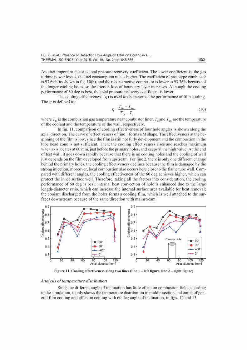
Another important factor is total pressure recovery coefficient. The lower coefficient is, the gas
turbine power losses, the fuel consumption rate is higher. The coefficient of prototype combustor
is 93.69% as shown in fig. 10(b), and the reconstructive combustor is lower to 93.36% because of
the longer cooling holes, so the friction loss of boundary layer increases. Although the cooling
performance of 60 deg is best, the total pressure recovery coefficient is lower.
The cooling effectiveness (h) is used to characterize the performance of film cooling.
The h is defined as:
h ��
�
T T
T T
m aw
m c
(10)
where Tm is the combustion gas temperature near combustor liner. Tc and Taw are the temperature
of the coolant and the temperature of the wall, respectively.
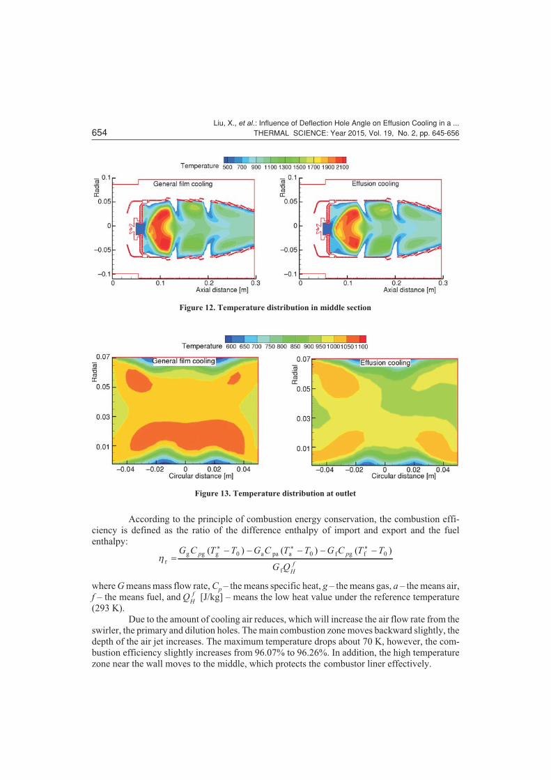
In fig. 11, comparison of cooling effectiveness of four hole angles is shown along the
axial direction. The curve of effectiveness of line 1 forms a M shape. The effectiveness at the be-
ginning of the film is low, since the film is still not fully development and the combustion in the
tube head zone is not sufficient. Then, the cooling effectiveness rises and reaches maximum
when axis locates at 60 mm, just before the primary holes, and keeps at the high value. At the end
of test wall, it goes down rapidly because that there is no cooling holes and the cooling of wall
just depends on the film developed from upstream. For line 2, there is only one different change
behind the primary holes, the cooling effectiveness declines because the film is damaged by the
strong injection, moreover, local combustion also occurs here close to the flame tube wall. Com-
pared with different angles, the cooling effectiveness of the 60 deg achieves higher, which can
protect the inner surface well. Therefore, taking all the factors into consideration, the cooling
performance of 60 deg is best: internal heat convection of hole is enhanced due to the large
length-diameter ratio, which can increase the internal surface area available for heat removal;
the coolant discharged from the holes forms a cooling film, which is well attached to the sur-
faces downstream because of the same direction with mainstream.
Analysis of temperature distribution
Since the different angle of inclination has little effect on combustion field according
to the simulation, it only shows the temperature distribution in middle section and outlet of gen-
eral film cooling and effusion cooling with 60 deg angle of inclination, in figs. 12 and 13.
Liu, X., et al.: Influence of Deflection Hole Angle on Effusion Cooling in a ...THERMAL SCIENCE: Year 2015, Vol. 19, No. 2, pp. 645-656 653
Figure 11. Cooling effectiveness along two lines (line 1 – left figure, line 2 – right figure)
According to the principle of combustion energy conservation, the combustion effi-
ciency is defined as the ratio of the difference enthalpy of import and export and the fuel
enthalpy:
hr
g g g a pa a f g f
f
�� � � � �G C T T G C T T G C T T
G Q
p p
H
f
( ) ( ) ( )* * *0 0 0
where G means mass flow rate, Cp – the means specific heat, g – the means gas, a – the means air,
f – the means fuel, and QH
f [J/kg] – means the low heat value under the reference temperature
(293 K).
Due to the amount of cooling air reduces, which will increase the air flow rate from the
swirler, the primary and dilution holes. The main combustion zone moves backward slightly, the
depth of the air jet increases. The maximum temperature drops about 70 K, however, the com-
bustion efficiency slightly increases from 96.07% to 96.26%. In addition, the high temperature
zone near the wall moves to the middle, which protects the combustor liner effectively.
Liu, X., et al.: Influence of Deflection Hole Angle on Effusion Cooling in a ...654 THERMAL SCIENCE: Year 2015, Vol. 19, No. 2, pp. 645-656
Figure 12. Temperature distribution in middle section
Figure 13. Temperature distribution at outlet

The maximum non-uniformity coefficient is used in this paper to indicate the non-uni-
formity of outlet, which is defined as the following formula. General requirements: qt � 30%,
qtm,out a,out
a,out a,in
��
�
T T
T T
where m means maximum and a means average.
Outlet temperature distribution trends consistent, but it is more uniform after the dilu-
tion holes because of the increasing combustion and dilution air and the maximum non-unifor-
mity coefficient is 27.93% and 24.67%, respectively. Turbine blades can be better protected in
the uniform temperature distribution in the outlet.
Conclusions
Three-dimensional coupled fluid-solid simulations are conducted to investigate the
performance of effusion cooling in the real combustion chamber condition. The reliability of the
simulation was proved by comparing predicted wall temperature distribution with measure-
ments. The cooling effectiveness of four deflection angle arrangements was investigated and the
conclusions are obtained as following.
� The cooling capacity of effusion is better than general film cooling, what's more, the coolant
flow rate is reduced by 20%, but the pressure loss is slightly increased.
� Due to the strong injection penetrates and damages the film and local combustion occurs, so
the wall temperature increases and the cooling effectiveness decreases behind the primary
holes.
� The cooling performance of 60 deg deflection angle is best. The effect of deflection angle is
not so significant on the coolant flow rate, but a large negative impact on the pressure loss.
The coolant is better attached to the wall downstream when the deflection angle is same as
the rotating mainstream.
� Due to the amount of cooling air reduces, the high temperature zone near the wall moves to
the middle and the maximum temperature drops about 70 K, the outlet temperature
distribution trends more consistent.
References
[1] Lefebvre, A. H., et al., Gas Turbine Combustion: Alternative Fuels and Emissions, CRC Press, BocaRaton, Fla., USA, 2010
[2] Li, L., et al., Combustion and Cooling Performance in an Aero-Engine Annular Combustor, Applied Ther-mal Engineering, 26 (2006), 16, pp. 1771-1779
[3] Ali, A. B. S., et al., Numerical Investigations of Cooling Holes System Role in the Protection of the Wallsof a Gas Turbine Combustion Chamber, Heat and Mass Transfer, 48 (2012), 5, pp. 779-788
Liu, X., et al.: Influence of Deflection Hole Angle on Effusion Cooling in a ...THERMAL SCIENCE: Year 2015, Vol. 19, No. 2, pp. 645-656 655
Nomenclature
C – specific heat capacity, [Jkg–1K–1]d – effusion hole diameter, [mm]f – mixture fraction
�f 2 – mixture fraction varianceH – staggered spacing, [mm]k – turbulent kinetic energy, [m2s–2]P – spanwise spacing, [mm]p(f ) – probability density functionPDF – probability density function
S – streamwise spacing, [mm]T – temperature, [K]
Greek symbols
d – wall thickness, [mm]e – kinetic energy dissipation rate, [m2s–3]h – cooling effectivenessl – thermal conductivity, [Wm–1K–1]

[4] Yu, Z., et al., Comparison of a Series of Double Chamber Models with Various Hole Angles for EnhancingCooling Effectiveness, International Communications in Heat and Mass Transfer, 44 (2013), May, pp.38-44
[5] Andrews, G. E., et al., Full Coverage Discrete Hole Film Cooling- The Influence of Hole Size, Interna-tional Journal of Turbo and Jet-Engines, 2 (1985), 3, pp. 213-225
[6] Andrews, G. E., Hussain, I., Small Diameter Film Cooling Holes: the Influence of Hole Size and Pitch, In-ternational Journal of Turbo and Jet Engines, 5 (1988), 1-4, pp. 61-72
[7] Andrews, G. E., et al., Full Coverage Discrete Hole Film Cooling: Cooling Effectiveness, InternationalJournal of Turbo and Jet-Engines, 2 (1985), 3, pp. 199-212
[8] Lin, Y., et al., Investigation of Film Cooling Effectiveness of Full-Coverage Inclined Multihole Wallswith Different Hole Arrangements, Proceedings, ASME Turbo Expo 2003: Power for Land, Sea, and Air,Atlanta, Geo., USA, 2003, Vol. 5, pp. 651-660
[9] Zhang, C., et al., Cooling Effectiveness of Effusion Walls with Deflection Hole Angles Measured by In-frared Imaging, Applied Thermal Engineering, 29 (2009), 5, pp. 966-972
[10] Lin, Y., et al., Measured Film Cooling Effectiveness of Three Multihole Patterns, Journal of Heat Trans-fer, 128 (2006), 2, pp. 192-197
[11] Scrittore, J. J., et al., Experimental Characterization of Film-Cooling Effectiveness Near Combustor Dilu-tion Holes, Proceedings, ASME Turbo Expo 2005: Power for Land, Sea, and Air, Reno, Nevada, USA,2005, Vol. 3, pp. 1339-1347
[12] Scrittore, J. J., et al., Investigation of Velocity Profiles for Effusion Cooling of a Combustor Liner, Journalof Turbomachinery, 129 (2007), 3, pp. 518-526
[13] Goldstein, R. J., Jin, P., Film Cooling Downstream of a Row of Discrete Holes with Compound Angle,Journal of Turbomachinery, 123 (2001), 2, pp. 222-230
[14] Ling, J. C. P. W., et al., Full Coverage Film Cooling for Combustor Transition Sections, Proceedings,ASME Turbo Expo 2002: Power for Land, Sea, and Air, Amsterdam, The Netherlands, 2002, Vol. 3, pp.1011-1021
[15] Gustafsson, K. M., Johansson, T. G., An Experimental Study of Surface Temperature Distribution on Ef-fusion-Cooled Plates, Journal of Engineering for Gas Turbines and Power, 123 (2001), 2, pp. 308-316
[16] Yang, C., Zhang, J., Influence of Multi-Hole Arrangement on Cooling Film Development, Chinese Jour-nal of Aeronautics, 25 (2012), 2, pp. 182-188
[17] Harrington, M. K., et al., Full-Coverage Film Cooling with Short Normal Injection Holes, Journal ofTurbomachinery, 123 (2001), 4, pp. 798-805
[18] Tarchi, L., et al., Experimental Investigation on the Effects of a Large Recirculating Area on the Perfor-mance of an Effusion Cooled Combustor Liner, Journal of Engineering for Gas Turbines and Power, 134(2012), 4, ID 041505
[19] Rohani, B., Saqr, K. M., Effects of Hydrogen Addition on the Structure and Pollutant Emissions of a Tur-bulent Unconfined Swirling Flame, International Communications in Heat and Mass Transfer, 39 (2012),5, pp. 681-688
[20] Zeinivand, H., Bazdidi-Tehrani, F., Influence of Stabilizer Jets on Combustion Characteristics and NOxEmission in a Jet-Stabilized Combustor, Applied Energy, 92 (2012), Apr., pp. 348-360
[21] Murthy, J. Y., Mathur, S. R., Finite Volume Method for Radiative Heat Transfer Using UnstructuredMeshes, Journal of Thermophysics and Heat Transfer, 12 (1998), 3, pp. 313-321
[22] Dang, X. X., Experimental Investigation and Numerical Simulation of A Gas Turbine Annular Combustorwith Dual-Stage Swirler, Ph. D. thesis, Nanjing University of Aeronautics and Astronautics, Nanjing,China, 2009
Paper submitted: January 7, 2014Paper revised: February 27, 2014Paper accepted: March 8, 2014
Liu, X., et al.: Influence of Deflection Hole Angle on Effusion Cooling in a ...656 THERMAL SCIENCE: Year 2015, Vol. 19, No. 2, pp. 645-656