informatics 43 – may 7, 2015. restatement of goals for testing want to verify software’s...
TRANSCRIPT

Informatics 43 – May 7, 2015

Restatement of Goals for Testing
Want to verify software’s correctness Need to test Need to decide on test cases No set of test cases is sufficient
What is a systematic approach to the selection of test cases that will lead to accurate, thorough, repeatable identification of bugs?

The Testing Process Model
1. Decide what to test.
2. Select a test case input.
3. Determine the expected output E.
4. Run the system with the test case input.
5. Capture the actual output A.
6. Compare E and A.
• Different? Inform programmer.
7. Loop back to 1 or 2, if time permits.

Back to Black box test case selection
Equivalence Class Partitioning – a systematic approach.
1. Identify the set of all possible inputs (to what is being tested).
2. Identify a basis for subdividing the set of inputs.• size, order, structure• correctness• stated requirements• your smarts
3. Use this basis for dividing the set of all possible inputs into subsets (domain into subdomains).
4. From each subset/subdomain, select a representative.

Basis _______________________
Input (Specific values)Expected Output
Notes from execution
Testing Matrix
Equivalence Class Partitions

Quiz Average - Basis Length of list
Input (Specific values)Expected Output
Notes from execution
Testing Matrix
Equivalence Class Partitions
0 [] 0.0
1 [87.3] 87.3
2 – 4 [90, 95, 85] 92.5
5 and up [80, 81, 82, 83, 84, 85, 86, 87, 86.0 88, 89, 90, 91]

Quiz Average - Basis Position of minimum value
Input (Specific values)ExpectedOutput
Notes from execution
Testing Matrix
Equivalence Class Partitions
First element [80, 87, 88, 89] 88.0
Middle element [87, 88, 80, 89] 88.0
[99, 98, 0, 97, 96] 97.5
Last element [87, 88, 89, 80] 88.0
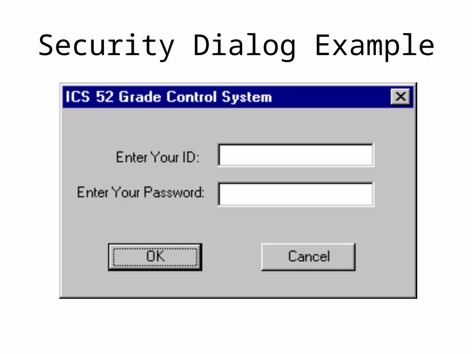
Security Dialog Example

Basis Security Dialog #1 – choice of button
Input (Specific values)ExpectedOutput
Notes from execution
Testing Matrix
Equivalence Partitions
Ok Button Press OK see Security Dialog #2
Cancel button Enter ID “R09”, press Cancel Text boxes are cleared, dialog remains Don’t enter ID, press Cancel Same.
X button Enter ID “R09”, press X Text boxes are cleared, dialog remains

Basis Security Dialog #2 – OK button pressed, validity of input
Input (Specific values)Expected Output
Notes from execution
Testing Matrix
Equivalence Partitions
Valid ID, TEST1, 77775555 Proceed toMatching PW Main screen
Valid ID, TEST1, 7777555 Audible beep,Wrong PW dialog remains.
Invalid ID, TES1, 77775555 Same

The Testing Process Model
1. Decide what to test.
2. Select a test case input.
3. Determine the expected output E.
4. Run the system with the test case input.
5. Capture the actual output A.
6. Compare E and A.
• Different? Inform programmer.
7. Loop back to 1 or 2, if time permits.
Where does this come from?
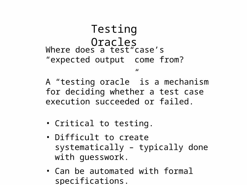
Testing Oracles
Where does a test case’s “expected output” come from?
A “testing oracle” is a mechanism for deciding whether a test case execution succeeded or failed.
• Critical to testing.
• Difficult to create systematically – typically done with guesswork.
• Can be automated with formal specifications.

Testing Oracle Example
The cosine function.
You test input = 0.5, the actual output is 0.8775825619.
What’s your oracle?
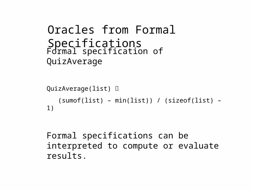
Oracles from Formal Specifications
Formal specification of QuizAverage
QuizAverage(list)
(sumof(list) – min(list)) / (sizeof(list) – 1)
Formal specifications can be interpreted to compute or evaluate results.

The Design Phase of Software Development
Something usually needs to be done after the user’s requirements are specified and before coding starts, especially on larger tasks.
1. Modularize the task so that multiple people can work on it.• Define modules and their interfaces.
2. Make system-wide decisions. • Architecture, languages, libraries, platforms.
3. Develop the specifications in more detail.• More “how”; consideration of trade-offs.

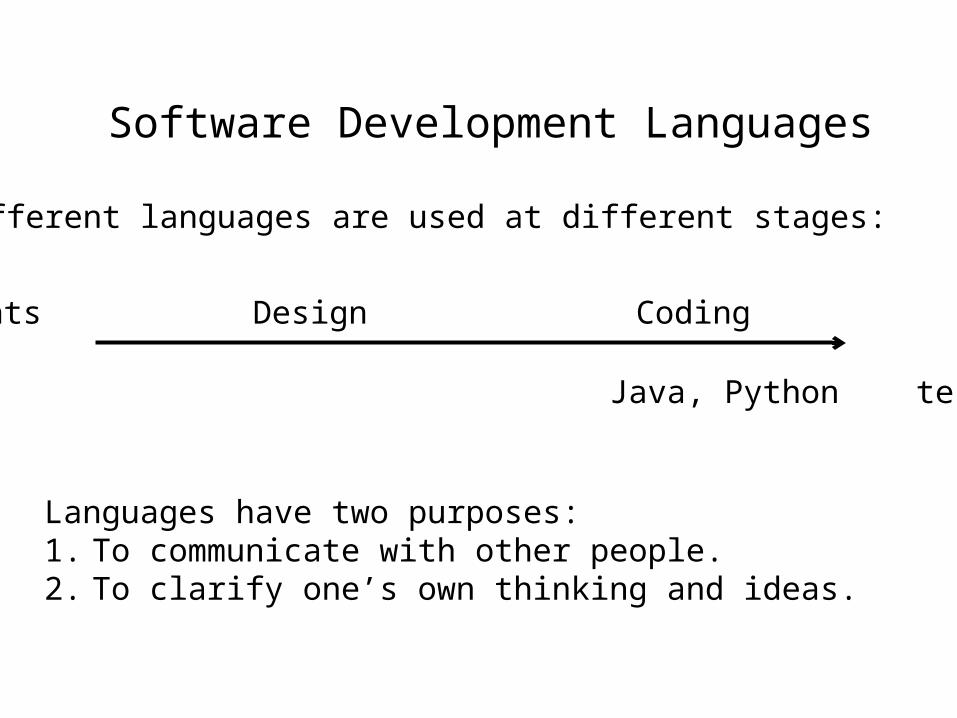
Software Development Languages
Requirements Design Coding Testing
English Java, Python testing matrix
Different languages are used at different stages:
Software Development Languages
Requirements Design Coding Testing
Different languages are used at different stages:
Languages have two purposes:1. To communicate with other people.2. To clarify one’s own thinking and ideas.
English Java, Python testing matrix

Deep thoughts about diagrams
It’s important to think of a diagram as being a statement in a language that has a syntax.
A diagram is not a picture.
A diagram has to be interpreted.
A B

What might this mean?
A B
• A happens before B.

Unified Modeling Language (UML)
A set of a dozen or so visual languages for expressing various aspects of software development.

UML Class Diagram

UML Use Case Diagram

UML Sequence Diagram

UML Activity Diagram

The UML Class Diagram helps in the decomposition of a system into sub-modules known as classes.
Some “object oriented” programming languages have “class” as part of the language’s syntax and design, but UML Class Diagrams can be created and used without reference to programming language classes.
Some following slides from www.cs.drexel.edu/~spiros/teaching/CS575/slides/uml.ppt

Software Design (UML)
Classes
ClassName
attributes
operations
A class is a description of a set of objects that share the same attributes,operations, relationships, and semantics.
Graphically, a class is rendered as a rectangle, usually including its name,attributes, and operations in separate,designated compartments.
Software Design (UML)
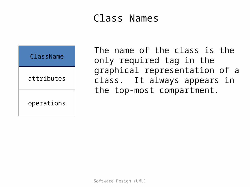
Class Names
ClassName
attributes
operations
The name of the class is the only required tag in the graphical representation of a class. It always appears in the top-most compartment.

Software Design (UML)
Class Attributes
Person
name : Stringaddress : Addressbirthdate : Datessn : Id
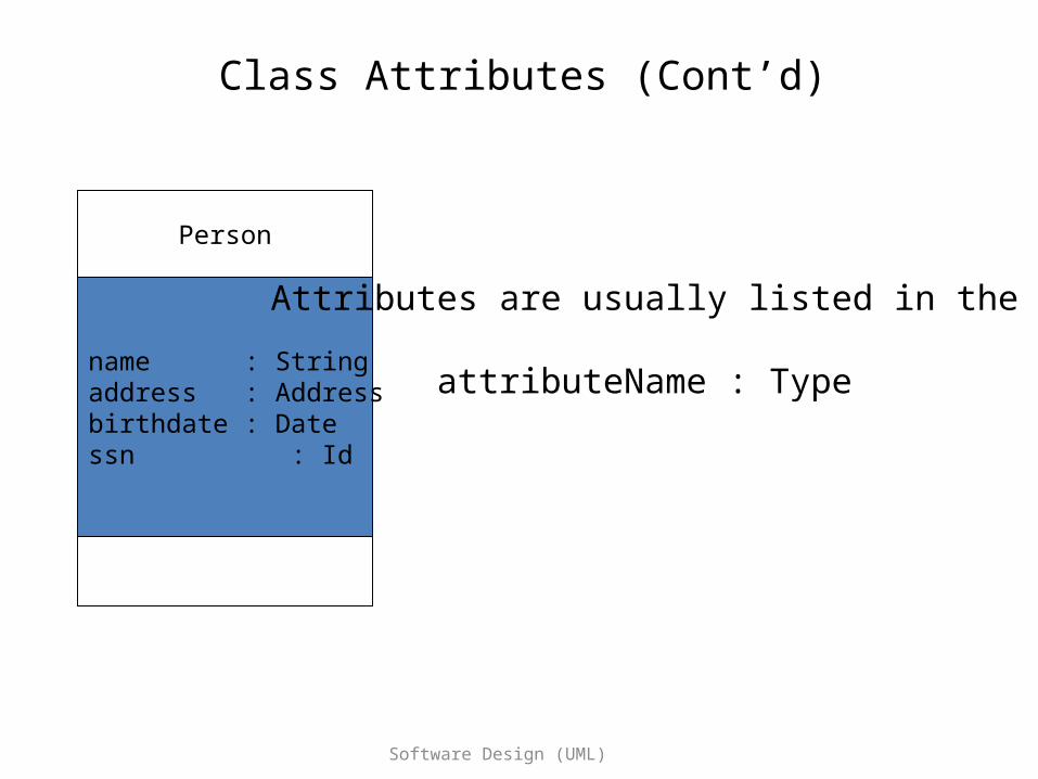
An attribute is a named property of a class that describes the object being modeled. In the class diagram, attributes appear in the second compartment just below the name-compartment.
Software Design (UML)
Class Attributes (Cont’d)
Person
name : Stringaddress : Addressbirthdate : Datessn : Id
Attributes are usually listed in the form:
attributeName : Type

Software Design (UML)
Class Operations
Person
name : Stringaddress : Addressbirthdate : Datessn : Id
eatsleepworkplay
Operations describe the class behavior and appear in the third compartment.

Software Design (UML)
Depicting Classes
Person
name : Stringbirthdate : Datessn : Id
eat()sleep()work()play()
When drawing a class, you needn’t show attributes and operations in every diagram.
Person
Person
nameaddress
birthdate
Person
eatplay
Person
Software Design (UML)
Association Relationships
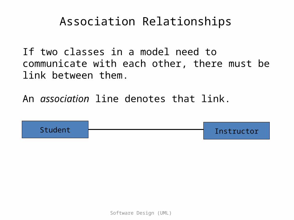
If two classes in a model need to communicate with each other, there must be link between them.
An association line denotes that link.
InstructorStudent

Software Design (UML)
Association Relationships (Cont’d)
We can constrain the association relationship by defining the navigability of the association.
Here, a Router object requests services from a DNS object by sending messages to (invoking the operations of) the server.
The direction of the association arrow indicates that the server has no knowledge of the Router.
Router DomainNameServer