ing 64 (cv) carburetor part 3 (idle circuit)
TRANSCRIPT

Bing 64 (CV) Carburetor Part 3 (Idle Circuit)
In Part 2 of this article, we talked about the starting carburetor (choke) system. We can run the engine at lower RPM settings only on the choke system, but as soon as we reset the choke system to the off position, the engine is now running on the idle circuit only. We often use this as a troubleshooting exercise. If the engine runs with the choke partially on, but dies as the choke is placed in the off position, it is an indi-cation that the idle circuit is the culprit. It is absolutely essential that the idle circuit be set up and functioning properly. We use the idle circuit on every flight, and it is a sur-prisingly important system within the carburetor. Aside from the practical aspects of having a properly operating idle circuit, there are many correlations with the idle cir-cuit malfunctioning and other engine problems, ranging from increased maintenance to engine stoppage and even engine failure.
If you follow our articles on a regular basis, you already have an insight into our underling premise that all successful troubleshooting, maintenance, and operation, comes as a result of a solid foundation of the theory and physics surrounding the subject matter. With that being said, let’s dig into the theory of the Idle circuit.
With the slide (piston) completely closed, the vac-uum present at the main fuel outlet is not suffi-cient to draw the fuel up from the main jet, through the mixing tube, nee-dle jet, and into the diffuser and throat of the carburetor. At low power settings we need to supplement the fuel air system with an auxiliary fuel-air system consisting of an idling air jet, Idle jet, bypass, idle outlet bore, and an idle mixture screw. (Figure: 1)
Figure: 1 Idle Circuit Components

The idling air jet is located on the inlet face of the carbu-retor and restricts the volume of air that can enter the idle mixture circuit. Manufactured from brass, it is pressed into the body of the carburetor and is normally not considered a replaceable component. The orifice size is approximately .020” in diameter. An orifice this small is easily plugged with contamination and one reason why it is located inside of the air cleaner.
The idle jet is made from brass. (Figure: 2) The jet size used on the Rotax 912 idle jet is a number 35 which designates that the orifice size as .35 mm. The jet is inset into the body of the carburetor inverted with the head of the jet facing down into the float bowl. This draws fuel through the jet orifice into the body of the jet. The body of the idle jet consists of eight radially drilled holes in the body. This acts as a fuel atomization
chamber which mixes the incoming air from the idle air jet with the fuel from the float bowl. This mixture is excessively rich and will be used to supplement the air that is coming through the carburetor, past the throttle valve.
The idle mixture screw (Figure: 3) is also manufactured from brass. The idle mixture screw works in conjunction with the idle outlet bore to create an adjustable needle valve. The fuel and air transitioning through the idle mixture screw and idle outlet bore have already been mixed. Allowing more of this already excessive-ly rich mixture into the carburetor will result in an enrichened fuel air ratio at idle. If you came up through the ultralight ranks, operating a two
stroke engine, you may be familiar with the idiom, which we used to remember which direction to turn the idle mixture screw, “in” richen, lean “out”. This works for the Bing 54 slide carburetors used on the Rotax 2-stroke engines. However, the Bing 64 CV carburetors are ex-actly the opposite. To enrichen the mixture we need to screw the idle mixture screw “out” or counterclockwise, and “in” or clockwise to lean out the mixture.(Figure: 4)
The bypass is located at the six o’clock position in the throttle body just under the throttle valve. These are two very small (.020”~) holes, nearly invisible, located coincidently Figure: 3 Idle Mixture Screw
Figure: 2 Idle Jet

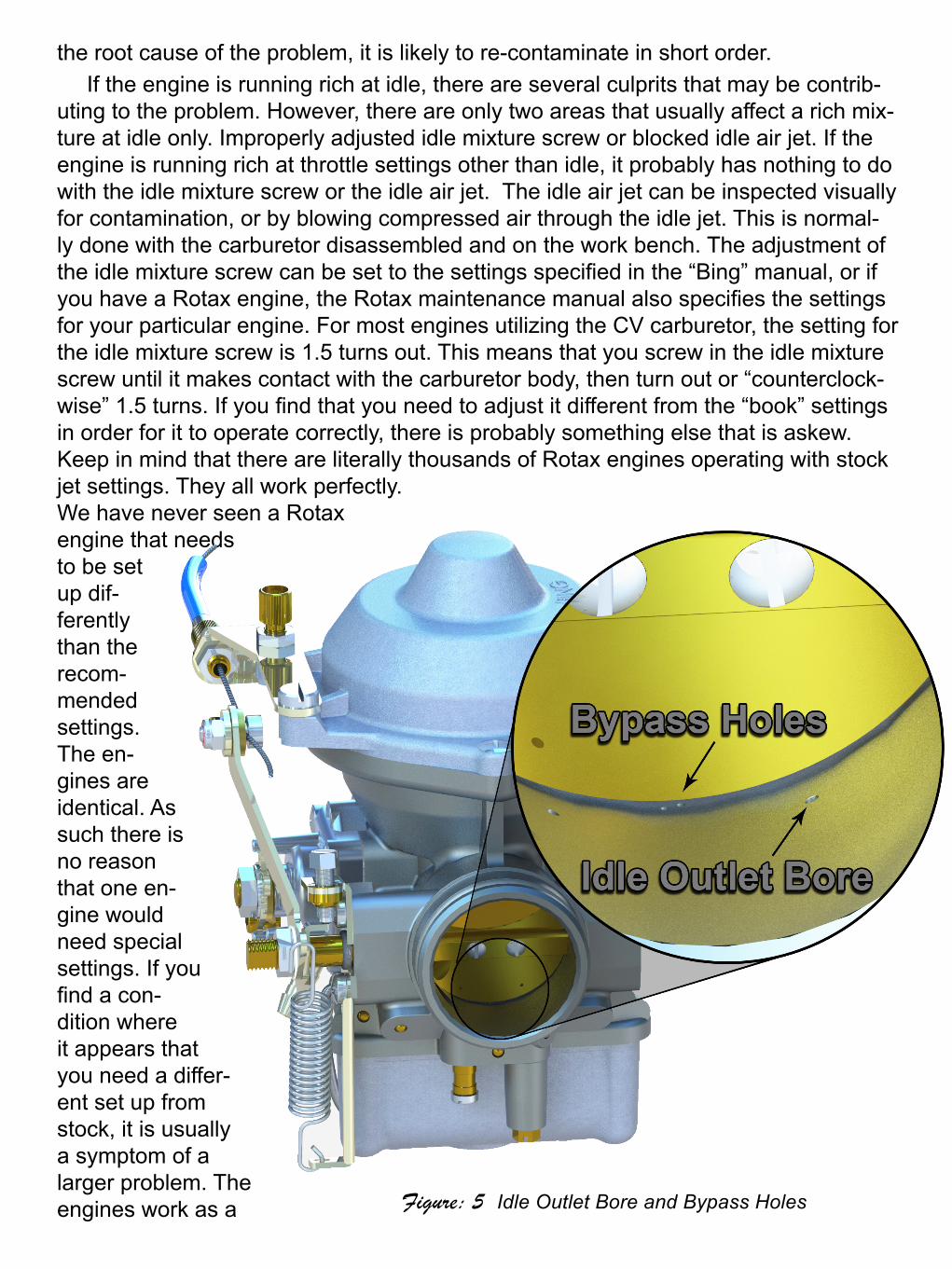
just at the position where the throttle valve makes contact with the body of the car-buretor. These holes work in conjunction with the idle outlet bore. The venturi effect created by the position of the throttle valve in relation to these two holes will vary the pressure within the bypass and internal passageways helping to regulate the mixture at the very lowest of throttle settings. (Figure: 5) During overhaul, failure to insure that all of these passageways are open and free from contamination will inevitably result in an engine that idles poorly.
Troubleshooting: the idle circuit and its effectiveness occurs from idle, up to about 25% throttle setting. (Figure: 6) This also shows that the jet needle and the needle jet have some effect down as low as 15% throttle setting. If the engine is running poorly at idle, but improves as the throttle is advanced passed the 15% throttle setting and then runs properly from 25% up through the mid-range and beyond, this would be an indication that the problem is related directly to something within the idle circuit. An engine that will not run at idle, but will run with the application of choke is an indica-tion the idle circuit is running lean. The most common, and probable cause, is that the idle jet has a blockage. It is not uncommon for old fuel to evaporate leaving a film or obstruction in the orifice for the idle jet. Remember that the idle jet used on the Ro-tax 912 is .35 mm. That is about the thickness of a business card and is very easy to become blocked. Replacing the jet with a new jet, or even cleaning the old jet is the easiest way to troubleshoot. But remember, if the idle jet has become blocked with debris, the more important question is what caused the blockage and why and how did it occur? Most of the time when we find “junk” in the Idle jet, we are concerned with how it got there. The stan-dard proce-dure would normally include flushing the fuel tanks, re-placement of fuel lines, and replacement or cleaning of the fuel filter. If contamination is present, and you simply clean the jet without addressing Figure: 4 Idle Circuit Passages Cut-away
the root cause of the problem, it is likely to re-contaminate in short order. If the engine is running rich at idle, there are several culprits that may be contrib-
uting to the problem. However, there are only two areas that usually affect a rich mix-ture at idle only. Improperly adjusted idle mixture screw or blocked idle air jet. If the engine is running rich at throttle settings other than idle, it probably has nothing to do with the idle mixture screw or the idle air jet. The idle air jet can be inspected visually for contamination, or by blowing compressed air through the idle jet. This is normal-ly done with the carburetor disassembled and on the work bench. The adjustment of the idle mixture screw can be set to the settings specified in the “Bing” manual, or if you have a Rotax engine, the Rotax maintenance manual also specifies the settings for your particular engine. For most engines utilizing the CV carburetor, the setting for the idle mixture screw is 1.5 turns out. This means that you screw in the idle mixture screw until it makes contact with the carburetor body, then turn out or “counterclock-wise” 1.5 turns. If you find that you need to adjust it different from the “book” settings in order for it to operate correctly, there is probably something else that is askew. Keep in mind that there are literally thousands of Rotax engines operating with stock jet settings. They all work perfectly. We have never seen a Rotax engine that needs to be set up dif-ferently than the recom-mended settings. The en-gines are identical. As such there is no reason that one en-gine would need special settings. If you find a con-dition where it appears that you need a differ-ent set up from stock, it is usually a symptom of a larger problem. The engines work as a Figure: 5 Idle Outlet Bore and Bypass Holes

symphony of different sub systems, all working in harmony with each other. The sub-systems within the engine and carburetor cannot be isolated from the bigger picture. For example, doing carburetor syn-chronization on the engine without first insuring the idle mixture screws have been properly adjusted is a waste of time. Mak-ing adjustments to one subsystem has an affect on all oth-
er systems. The good news is, once you understand the subsys-tems within the carburetor, the abil-ity to keep them operating correctly is really quite easy and simple.
© Rainbow Aviation 2017 Carol and Brian CarpenterCarol and Brian Carpenter are owners of Rainbow Aviation Services in Corn-ing, California. For more Information visit www.rainbowaviation.com
Figure: 6 Jet Effectiveness Vs Throttle Position