injection locked gunn diode oscillators oscillator · pdf fileinjection locked gunn diode...
TRANSCRIPT
5-48High quality microwave and millimeterwave components and subsystems. Visit Ducommun Technologies online at www.ducommun.com.
Injection Locked Gunn Diode Oscillators
High output powerModerate gain and bandwidthCW operation Frequency up to 110 GHz
Power amplificationLocal oscillatorsMultiplier driversSubsystems
APPLICATIONS
OGI series CW injection-locked Gunn oscillators are alternatives to HEMT device and IMPATT diode based stable amplifiers, especially at high millimeterwave frequencies. The operating frequency and power output of these oscillators are up to 110 GHz and 24 dBm. The spectrum purity of the output signal is injected signal dependent. There is an output free running signal in the absence of an input injection signal. The oscillators are provided with integral circulators and optional DC voltage regulator. An optional heater is provided to achieve better temperature stability. For higher gain, broader locking bandwidth and higher output, multi-stage and multi-diodes configurations are used. The operating temperature range is 0 to +50°C.
DESCRIPTION
SPECIFICATIONS
Bulletin No. OGI
OGI Series
FEATURES
Frequency Range (GHz)
Input Power (dBm)
Output Power
(dBm, Min)
Locking Bandwidth (GHz, Max)
Bias Voltage Range (Volts)
Bias Current Range
(A)
Waveguide Size
Outline Drawing
26.5-40 0 to 10 24 1.5 4-12 0.3-2.5 WR-28 *33-50 0 to 10 23 2.0 4-11 0.3-2.0 WR-22 *40-60 0 to 10 22 2.0 3-10 0.3-2.0 WR-19 *50-75 0 to 10 20 2.0 3-10 0.3-1.5 WR-15 *60-90 0 to 10 19 2.0 3-10 0.25-1.5 WR-12 *75-110 0 to 10 19 2.0 4-10 0.25-1.5 WR-10 *
Temperature Range 0 to +50 °C
Specify Model Number OGI-CO CF BW PP - XX
Output Power in dBmBandwidth in 1/10 GHzCenter Frequency in GHz
RF Connector Type
Example: To order a center frequency 60 GHz injection locked Gunn oscillator with WR-15 waveguide interface, 2 GHz locking bandwidth and 17 dBm output power, specify OGI-15602017-XX.
Factory Reserve
HOW TO ORDER
* Consult factory for outlines.
5-49High quality microwave and millimeterwave components and subsystems. Visit Ducommun Technologies online at www.ducommun.com.
5
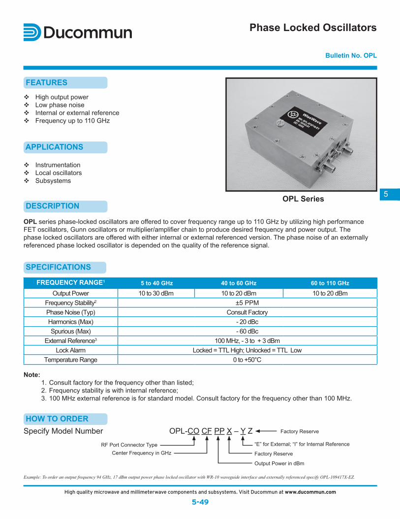
Phase Locked Oscillators
FEATURES
High output powerLow phase noiseInternal or external reference Frequency up to 110 GHz
InstrumentationLocal oscillatorsSubsystems
APPLICATIONS
OPL series phase-locked oscillators are offered to cover frequency range up to 110 GHz by utilizing high performance FET oscillators, Gunn oscillators or multiplier/amplifier chain to produce desired frequency and power output. The phase locked oscillators are offered with either internal or external referenced version. The phase noise of an externally referenced phase locked oscillator is depended on the quality of the reference signal.
DESCRIPTION
Bulletin No. OPL
OPL Series
SPECIFICATIONS
FREQUENCY RANGE1 5 to 40 GHz 40 to 60 GHz 60 to 110 GHz
Output Power 10 to 30 dBm 10 to 20 dBm 10 to 20 dBmFrequency Stability2 ±5 PPMPhase Noise (Typ) Consult FactoryHarmonics (Max) - 20 dBcSpurious (Max) - 60 dBc
External Reference3 100 MHz, - 3 to + 3 dBmLock Alarm Locked = TTL High; Unlocked = TTL Low
Temperature Range 0 to +50°C
Specify Model Number OPL-CO CF PP X – Y Z“E” for External; “I” for Internal Reference
Output Power in dBm
Center Frequency in GHzRF Port Connector Type
Example: To order an output frequency 94 GHz, 17 dBm output power phase locked oscillator with WR-10 waveguide interface and externally referenced specify OPL-109417X-EZ.
Factory Reserve
HOW TO ORDER
Note: 1. Consult factory for the frequency other than listed; 2. Frequency stability is with internal reference; 3. 100 MHz external reference is for standard model. Consult factory for the frequency other than 100 MHz.
Factory Reserve
High quality microwave and millimeterwave components and subsystems. Visit Ducommun at www.ducommun.com
5-495-51High quality microwave and millimeterwave components and subsystems. Visit Ducommun Technologies online at www.ducommun.com.
5
4-40 x 0.28 DPC'BORE 0.120 x 0.06 DP
4 PLS
WiseWaveM/N: XXXXXS/N: XXXXXD/C: XX/XX
4-40 x 0.28 DPC'BORE 0.120 x 0.06 DP
4 PLS
WiseWaveM/N: XXXXXS/N: XXXXXD/C: XX/XX
0.089 DIA x THRU4 PLS
WAVEGUIDEW/FLANGE TUNER
4-40 x 0.15 DP2 PLS
WAVEGUIDEW/FLANGE
4-40 x 0.15 DP2 PLS
2-56 x 0.15 DP2 PLS
WR-28 WAVEGUIDEW/UG599/U FLANGE
4-40 x 0.15 DP2 PLS
FREQUENCY TUNNER
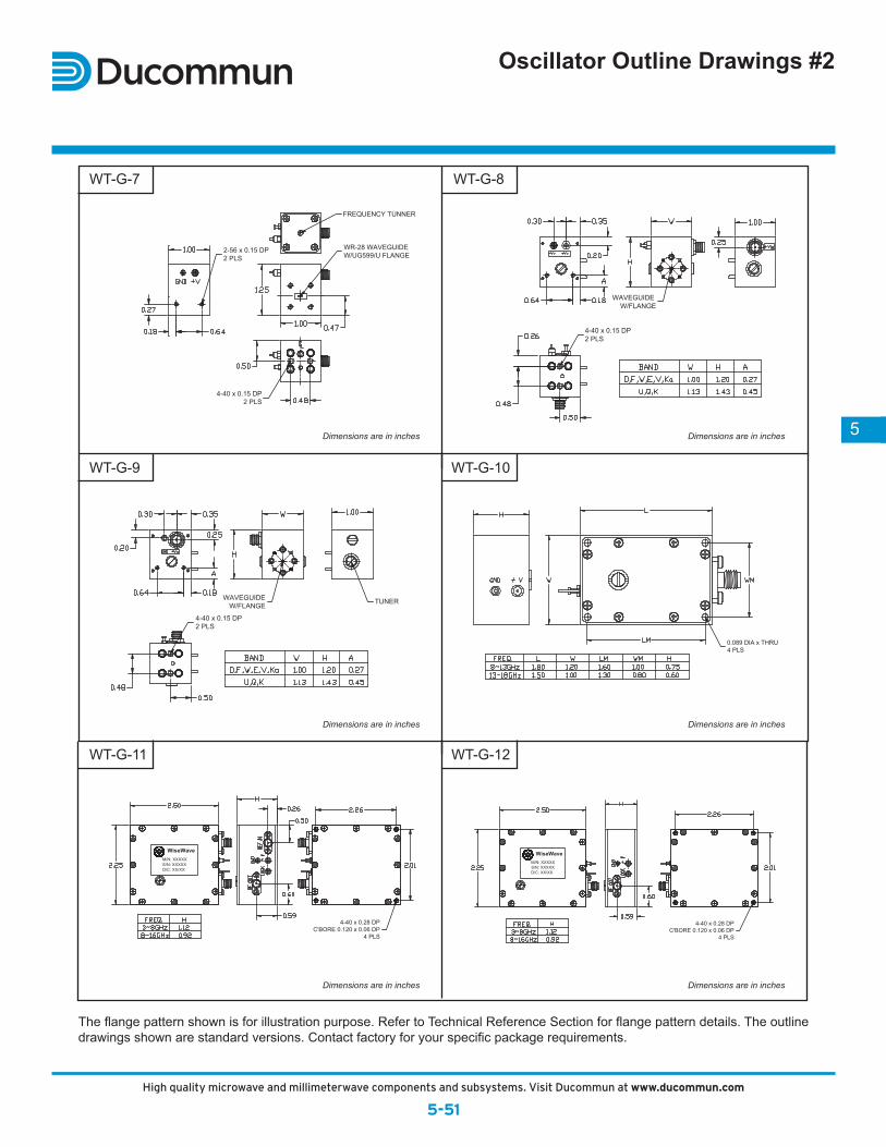
Oscillator Outline Drawings #2
The flange pattern shown is for illustration purpose. Refer to Technical Reference Section for flange pattern details. The outline drawings shown are standard versions. Contact factory for your specific package requirements.
Dimensions are in inches
Dimensions are in inches
Dimensions are in inches
Dimensions are in inches
Dimensions are in inches
Dimensions are in inches
WT-G-7
WT-G-9
WT-G-11
WT-G-8
WT-G-10
WT-G-12
76155_DucMMWaveCat.indd 49 3/17/14 2:17 PM
5-50High quality microwave and millimeterwave components and subsystems. Visit Ducommun Technologies online at www.ducommun.com.
WAVEGUIDEW/FLANGE
2-56 x 0.15 DP2 PLS
4-40 x 0.15 DP2 PLS
WAVEGUIDEW/FLANGE
2-56 x 0.15 DP2 PLS
FREQUENCY TUNER
4-40 x 0.15 DP2 PLS
4-40 x 0.15 DP2 PLS
FREQUENCY TUNER
POWER TUNER
BIAS PORT
0.14 DIA X 0.38 DPWR-10/WR-12/WR-15W/UG387/U FLANGE
4-40 x 0.15 DP2 PLS
2-56 x 0.15 DP2 PLS
WAVEGUIDEW/FLANGE
WR-28 WAVEGUIDEW/UG599/U FLANGE
WAVEGUIDEW/FLANGE
2-56 x 0.15 DP2 PLS
4-40 x 0.15 DP2 PLS
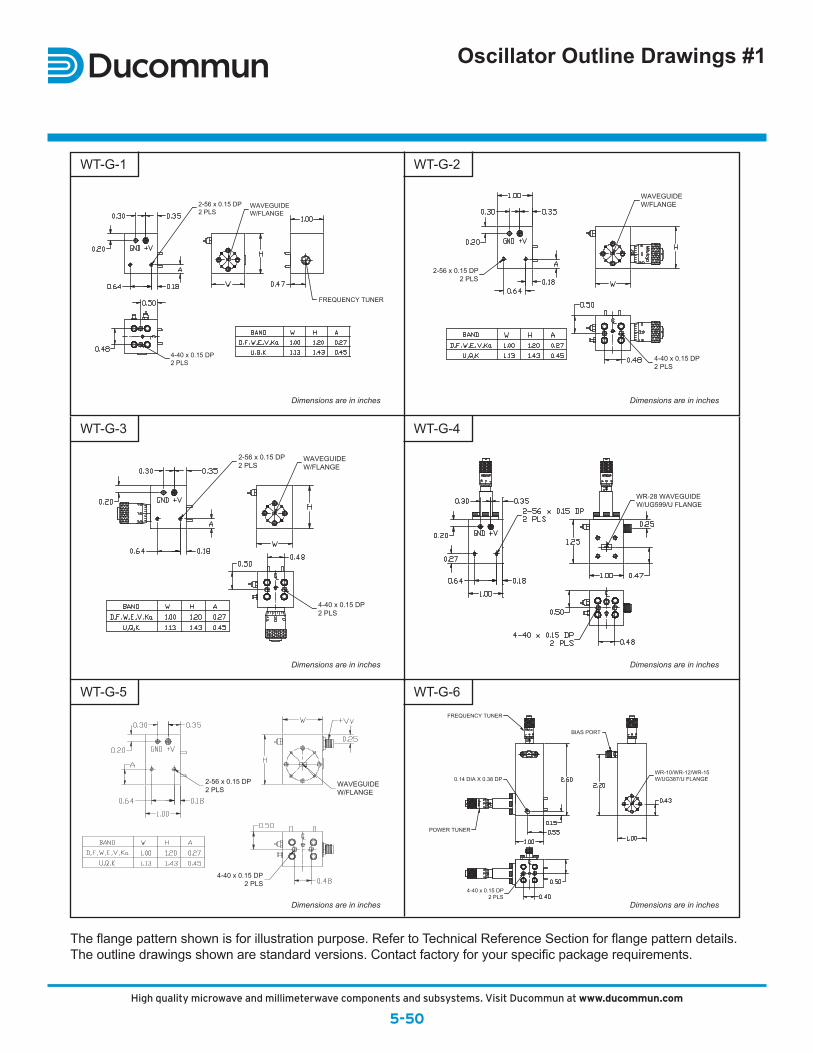
Oscillator Outline Drawings #1
The flange pattern shown is for illustration purpose. Refer to Technical Reference Section for flange pattern details. The outline drawings shown are standard versions. Contact factory for your specific package requirements.
Dimensions are in inches
Dimensions are in inches
Dimensions are in inches
Dimensions are in inches
Dimensions are in inches
Dimensions are in inches
WT-G-1
WT-G-3
WT-G-5
WT-G-2
WT-G-4
WT-G-6
5-51High quality microwave and millimeterwave components and subsystems. Visit Ducommun Technologies online at www.ducommun.com.
5
4-40 x 0.28 DPC'BORE 0.120 x 0.06 DP
4 PLS
WiseWaveM/N: XXXXXS/N: XXXXXD/C: XX/XX
4-40 x 0.28 DPC'BORE 0.120 x 0.06 DP
4 PLS
WiseWaveM/N: XXXXXS/N: XXXXXD/C: XX/XX
0.089 DIA x THRU4 PLS
WAVEGUIDEW/FLANGE TUNER
4-40 x 0.15 DP2 PLS
WAVEGUIDEW/FLANGE
4-40 x 0.15 DP2 PLS
2-56 x 0.15 DP2 PLS
WR-28 WAVEGUIDEW/UG599/U FLANGE
4-40 x 0.15 DP2 PLS
FREQUENCY TUNNER
Oscillator Outline Drawings #2
The flange pattern shown is for illustration purpose. Refer to Technical Reference Section for flange pattern details. The outline drawings shown are standard versions. Contact factory for your specific package requirements.
Dimensions are in inches
Dimensions are in inches
Dimensions are in inches
Dimensions are in inches
Dimensions are in inches
Dimensions are in inches
WT-G-7
WT-G-9
WT-G-11
WT-G-8
WT-G-10
WT-G-12
High quality microwave and millimeterwave components and subsystems. Visit Ducommun at www.ducommun.com
5-50
76155_DucMMWaveCat.indd 50 3/17/14 2:17 PM
5-50High quality microwave and millimeterwave components and subsystems. Visit Ducommun Technologies online at www.ducommun.com.
WAVEGUIDEW/FLANGE
2-56 x 0.15 DP2 PLS
4-40 x 0.15 DP2 PLS
WAVEGUIDEW/FLANGE
2-56 x 0.15 DP2 PLS
FREQUENCY TUNER
4-40 x 0.15 DP2 PLS
4-40 x 0.15 DP2 PLS
FREQUENCY TUNER
POWER TUNER
BIAS PORT
0.14 DIA X 0.38 DPWR-10/WR-12/WR-15W/UG387/U FLANGE
4-40 x 0.15 DP2 PLS
2-56 x 0.15 DP2 PLS
WAVEGUIDEW/FLANGE
WR-28 WAVEGUIDEW/UG599/U FLANGE
WAVEGUIDEW/FLANGE
2-56 x 0.15 DP2 PLS
4-40 x 0.15 DP2 PLS
Oscillator Outline Drawings #1
The flange pattern shown is for illustration purpose. Refer to Technical Reference Section for flange pattern details. The outline drawings shown are standard versions. Contact factory for your specific package requirements.
Dimensions are in inches
Dimensions are in inches
Dimensions are in inches
Dimensions are in inches
Dimensions are in inches
Dimensions are in inches
WT-G-1
WT-G-3
WT-G-5
WT-G-2
WT-G-4
WT-G-6
5-51High quality microwave and millimeterwave components and subsystems. Visit Ducommun Technologies online at www.ducommun.com.
5
4-40 x 0.28 DPC'BORE 0.120 x 0.06 DP
4 PLS
WiseWaveM/N: XXXXXS/N: XXXXXD/C: XX/XX
4-40 x 0.28 DPC'BORE 0.120 x 0.06 DP
4 PLS
WiseWaveM/N: XXXXXS/N: XXXXXD/C: XX/XX
0.089 DIA x THRU4 PLS
WAVEGUIDEW/FLANGE TUNER
4-40 x 0.15 DP2 PLS
WAVEGUIDEW/FLANGE
4-40 x 0.15 DP2 PLS
2-56 x 0.15 DP2 PLS
WR-28 WAVEGUIDEW/UG599/U FLANGE
4-40 x 0.15 DP2 PLS
FREQUENCY TUNNER
Oscillator Outline Drawings #2
The flange pattern shown is for illustration purpose. Refer to Technical Reference Section for flange pattern details. The outline drawings shown are standard versions. Contact factory for your specific package requirements.
Dimensions are in inches
Dimensions are in inches
Dimensions are in inches
Dimensions are in inches
Dimensions are in inches
Dimensions are in inches
WT-G-7
WT-G-9
WT-G-11
WT-G-8
WT-G-10
WT-G-12
High quality microwave and millimeterwave components and subsystems. Visit Ducommun at www.ducommun.com
5-515-51High quality microwave and millimeterwave components and subsystems. Visit Ducommun Technologies online at www.ducommun.com.
5
4-40 x 0.28 DPC'BORE 0.120 x 0.06 DP
4 PLS
WiseWaveM/N: XXXXXS/N: XXXXXD/C: XX/XX
4-40 x 0.28 DPC'BORE 0.120 x 0.06 DP
4 PLS
WiseWaveM/N: XXXXXS/N: XXXXXD/C: XX/XX
0.089 DIA x THRU4 PLS
WAVEGUIDEW/FLANGE TUNER
4-40 x 0.15 DP2 PLS
WAVEGUIDEW/FLANGE
4-40 x 0.15 DP2 PLS
2-56 x 0.15 DP2 PLS
WR-28 WAVEGUIDEW/UG599/U FLANGE
4-40 x 0.15 DP2 PLS
FREQUENCY TUNNER
Oscillator Outline Drawings #2
The flange pattern shown is for illustration purpose. Refer to Technical Reference Section for flange pattern details. The outline drawings shown are standard versions. Contact factory for your specific package requirements.
Dimensions are in inches
Dimensions are in inches
Dimensions are in inches
Dimensions are in inches
Dimensions are in inches
Dimensions are in inches
WT-G-7
WT-G-9
WT-G-11
WT-G-8
WT-G-10
WT-G-12
76155_DucMMWaveCat.indd 51 3/17/14 2:17 PM