inlet vacuum filters - bombas de vacío bolivia becker
TRANSCRIPT

Inlet Vacuum Filters
www.solbergmfg.com
Inle
t Vac
uum
Filt
ers
Technical Data pg. 4-2 “L” Style Compact Vacuum Filters CSL Series 3/8” - 3” BSPP, 31 - 510 m3/h pg. 4-4 ISO Flg CSL Series NW16-K100, 31 - 510 m3/h pg. 4-5 “L” Style Large Vacuum Filters CSL Series: 3” - 6” BSPT, 510 - 1870 m3/h pg. 4-6 CSL Series: DN80 - DN300, 510 - 8415 m3/h pg. 4-6 ISO Flg “L” Style Large Vacuum Filters CSL Series: K160 - K320, 1870 - 8415 m3/h pg. 4-8 “T” Style Compact Vacuum Filters CT Series: 1”- 6”BSPP, 68- 1870 m3/h pg. 4-9 ST Series: 1” - 4”BSPP, 68 - 884 m3/h pg. 4-10 Extreme Duty SpinMeister™ Vacuum Filters STSML Series: 2” - 6” BSPP, 68 - 1530 m3/h pg. 4-11 Vacuum Filters for Medical Facili es HV Series: 2” - 4”, 175 - 340 m3/h pg. 4-12 See-Through Liquid Separators STS Series: 1” - 4”, 68- 850 m3/h pg. 4-13 Liquid Separator/Vacuum Filters LRS Series: 2” - 4”, 105 - 1415 m3/h pg. 4-14 SRS Series: DN150 - DN250, 2170 - 3060 m3/h pg. 4-15 Vapor Condensing Separator Traps JRS Series pg. 4-16 JCT/JST Series (Compact) pg. 4-17 Natural Gas Filtra on: Suc on Scrubbers pg. 4-18 Vacuum Filtra on for Solar, Semi-Con, LED, Coa ng RX Series: Reverse Pulse System pg. 4-19 Pressure Drop Gauges pg. 4-20 Drain Systems pg. 4-21

Technical Data Inlet Vacuum Filters
Pg. 4-2
www.solbergmfg.com • [email protected] • Tel: +1 630 616 4900 • Fax: +1 630 773 2643
Applications & Equipment Industrial & Severe Duty
Vacuum Pumps & Systems: Roots, Rotary Vane, Screw, Piston Vacuum Packaging Equipment
Vacuum Furnace
Blowers: Side Channel & Roots (P.D.)
Vacuum Li ers
Intake Suc on Filters
Food Industry
Woodworking/Routers
Ash Handling
Prin ng Industry
Medical/Hospital
Remote Installa ons for Piston & Screw Compressors Paper Processing
Waste Water Aera on
Cement Processing
Bag House Systems
Vacuum Vent Breathers
Chemical Processing
Factory Automa on Equipment
Leak Detec on Systems
Identification
CSL-235P-DN100
Filter Type Replacement Element
Part Number Connec on
Size and Type
Standard Solberg assemblies should have an iden fica on label/nameplate that gives the following informa on:
Assembly Model # Replacement Element #
The part number designates the filter type, the element configura on and housing connec on size. For example, the following part number iden fies the filter as being a “CSL” design filter with a “235” element, “P” prefilter and DN100 flange connec on size.
Inle
t Vac
uum
Filt
ers
Vacuum Service Rating Chart Threaded vacuum filter connec ons must be free of defect and properly sealed to achieve deeper vacuum levels. Vacuum service levels are given for reference only and serve as a guideline for product selec on. Product cer fica on and alterna ve designs are available for applica ons requiring deeper vacuum levels and specific leak rates. Please contact factory for details.
Pg. 4-2
Pressure (mbar) Pressure (Torr) Pressure (Pa)Atmospheric Pressure 1013 760 1.013×10+5
Coarse Vacuum 1013 to 33 760 to 25 1×10+5 to 3×10+3
Medium Vacuum 33 to 1.3×10⁻³ 25 to 1×10⁻³ 3×10+3 to 1×10⁻¹
High Vacuum 1.3×10⁻³ to 1.3×10⁻⁹ 1×10⁻³ to 1×10⁻⁹ 1×10⁻¹ to 1×10⁻⁷

Technical Data Inlet Vacuum Filters
Pg. 4-3 www.solbergmfg.com • [email protected] • Tel: +1 630 616 4900 • Fax: +1 630 773 2643
Choosing the Best Filter for your Equipment
Element Maintenance
Solberg elements should be replaced, once the pressure drop reaches 37-50 mbar above the ini al pressure drop of the installa on. Cleaning an element is also an op on. Solberg recommends replacing dirty elements for op mal performance. Any damage which results from by-pass or addi onal pressure drop created by element cleaning is the sole responsibility of the operator. Note: The overall performance of a filter element is altered once cleaned. The ini al pressure drop a er subsequent cleanings will be greater than the original, clean pressure drop of the element. A er each cleaning, the pressure drop will con nue to increase. Under all circumstances, the ini al pressure drop of the element needs to be maintained at less than 37 mbar. If the pressure drop exceeds 50 mbar at start-up; it should be replaced with a new element. With many types of equipment, the maximum pressure drop allowed will be dictated by the ability of the equipment to perform to its rated capacity. Under all circumstances, the operator should avoid exceeding the manufacturer’s recommended maximum pressure drop for their specific equipment.
Inle
t Vac
uum
Filt
ers
A. Connec on & Airflow Known: When the connec on & airflow is known: 1. Select appropriate connec on style. (i.e.: BSPT, Flange, BSPP, etc.)
2. Check assembly m3/h (flow) ra ng. Compare with your required airflow. (Note: Assembly flow ra ngs are based on 6,000 FPM or 30m/sec for a given connec on size to achieve low pressure drop performance. When required flow exceeds assembly flow ra ng, the pressure drop through the outlet connec on will increase. In such cases select by element m3/h (flow) ra ng.)
3. When required flow ra ng matches connec on size; skip to “C. Selec ng Elements”. B. Unknown Connec on: When the connec on size is unknown, flexible, or the required flow ra ng
exceeds assembly flow ra ng: 1. Match required flow ra ng with the element flow ra ng. 2. Choose related connec on size. C. Selec ng Elements: The filter performance is influenced by the actual applica on duty and the
equipment it is installed on. Regular maintenance checks and proper servicing is required. Applica on Duty Descrip ons: Industrial Duty: Clean workshop or clean outdoor environment - small element sizing is sufficient. Severe Duty: Dirty workshop, wastewater – medium to large element is recommended. Extreme Duty: Cement, steel making, plas cs or dusty material conveying – Largest element sizing is
recommended. 1. Select media required by your applica on. Op ons include:
a. Standard media 1. Polyester: All purpose; it withstands pulses, moisture, and oily air 2. Paper: Mostly dry, smooth flow applica ons
b. Special Media: For a variety of micron levels and media types, see the “Filter Media Specifica ons” in the Replacement Element Sec on.
2. Select Element size by matching the element with the an cipated duty and upsize accordingly.
Request the appropriate maintenance manual for more in-depth informa on from your Solberg representa ve or through www.solbergmfg.com.
Filter Assembly Maintenance

Pg. 4-4
Features
• Vacuum gauge • Higher holding capacity configura ons available (select models) • Material/Finishes: stainless steel, epoxy coa ng • Support brackets • Alterna ve top-to-canister fastening system for low pressure or pulsa ng systems • Stainless steel (select models)
Options • Vacuum Ra ng: Medium vacuum service** • Temp (con nuous): min -26°C (-15°F) max 104°C (220°F) • Filter change out differen al: 37-50 mbar over ini al ΔP • Polyester: 99%+ removal efficiency standard to 5 micron • Paper: 99%+ removal efficiency standard to 2 micron **See Vacuum Filter Technical Data for Vacuum Service Data.
Technical Specifications
• Seamless drawn housings • O-ring seal • Corrosion resistant carbon steel construc on • Powder coat finish • Stainless steel torsion clips for durability
www.solbergmfg.com • [email protected] • Tel: +1 630 616 4900 • Fax: +1 630 773 2643
A
B
C Outlet
Inlet
Note: Model offerings & design parameters may change without no ce. Contact Solberg for CAD drawings or see www.solbergmfg.com.
• Large dirt holding capacity and easy field cleaning, especially when mounted horizontally or inverted • Low pressure design
Benefits
See Vacuum Filter Technical Data sec on for sizing guidelines.
D
E
Note: NPSC threaded housings are interchangeable with BSPP up to 1”.
Inle
t Vac
uum
Filt
ers
ATEX Available
”L” Style Compact Vacuum Filters CSL Series 3/8” - 3”
Config. A Config. B
Config. C
Config. D Config. E
Inlet/ Inlet/ Assembly Suggested Approx. ElementOutlet Outlet m3/h Housing Dimensions - mm Service HT. Weight m3/hSize Type Rating Config. Polyester Paper A B C D E kg Polyester Paper Rating3/8" BSPP 31 A CSL-825-039HCB CSL-824-039HCB 85 54 95 46 76 0.40 825 824 431/2" NPSC 31 A CSL-825-050HCB CSL-824-050HCB 89 57 95 49 76 0.40 825 824 431/2" NPSC 34 B CSL-843-050HCB CSL-842-050HCB 103 76 146 64 83 1.4 843 842 943/4" NPSC 41 A CSL-825-075HCB CSL-824-075HCB 89 58 95 50 76 0.40 825 824 433/4" NPSC 43 B CSL-843-075HCB CSL-842-075HCB 103 76 146 64 83 1.4 843 842 94
1" BSPP 60 B CSL-843-101HCB CSL-842-101HCB 111 83 146 67 83 1.4 843 842 941" BSPP 68 C CSL-849-101HCB CSL-848-101HCB 170 105 187 114 133 2.3 849 848 196
1 1/4" BSPP 94 B CSL-843-126HCB CSL-842-126HCB 111 83 146 67 83 1.4 843 842 941 1/4" BSPP 102 C CSL-849-126HCB CSL-848-126HCB 170 105 187 114 133 2.3 849 848 1961 1/2" BSPP 136 C CSL-849-151HCB CSL-848-151HCB 171 105 187 114 133 2.3 849 848 196
2" BSPP 298 D CSL-851-201HCB CSL-850-201HCB 260 114 222 127 235 6.8 851 850 4932 1/2" BSPP 357 D CSL-851-251HCB CSL-850-251HCB 271 130 222 140 235 6.8 851 850 493
3" BSPP 510 E CSL-239-301HCB CSL-238-301HCB 361 186 337 183 279 15 239 238 969
Element Part No.Replacement
Assembly Part Number

”L” Style Vacuum Filters ISO CSL Series NW16 - NW40 FLG
Pg. 4-5 www.solbergmfg.com • [email protected] • Tel: +1 630 616 4900 • Fax: +1 630 773 2643
• ISO flange connec ons - Stainless steel ISO flange - Buna o-ring sealed • Seamless drawn housings • Corrosive resistant carbon steel construc on • Powder coat finish (Black models) • O-ring housing seal • Stainless steel torsion clips
Features
• Vacuum Leak Rate: 1x10⁻⁵ mbar l/sec • Vacuum Ra ng: Medium vacuum service** • Temp (con nuous): min -26°C (-15°F) max 104°C (220°F) • Filter change out differen al: 37-50 mbar over ini al Δ P • Polyester: 99%+ removal efficiency standard to 5 micron • Paper: 99%+ removal efficiency standard to 2 micron **See Vacuum Filter Technical Data for Vacuum Service Data.
Technical Specifications Options
• Prevent dry scroll p seal migra on • Polycrystalline silicone ingot produc on • Vacuum coa ng • Solar cell lamina on • Trap condensable vapors • Thin-film manufacturing • Protect against backstreaming
Series Specific Applications
See Vacuum Filter Technical Data sec on for sizing guidelines.
A
B
C Outlet
Inlet
D
• Contact factory for larger sizes • Viton seals • Stainless steel (select models) • Ac vated Alumina, Ac vated Zeolite media available for foreline trap and other applica ons
Inle
t Vac
uum
Filt
ers
SS ISO Flange Black Housing Finish
SS ISO Flange Nickel Housing Finish
ATEX Available
Note: Model offerings & design parameters may change without no ce. Contact Solberg for CAD drawings or see www.solbergmfg.com.
ISO Flg Assembly Approx. ElementInlet & m3/h Dimensions - mm Weight m3/hOutlet Rating Polyester Paper A B C D kg Polyester Paper RatingNW16 39 CSL-825-NW16B CSL-824-NW16B 99 67 95 58 0.4 825 824 42NW25 42 CSL-825-NW25B CSL-824-NW25B 99 67 95 58 0.4 825 824 42NW25 59 CSL-843-NW25B CSL-842-NW25B 111 86 146 66 1 843 842 93NW40 93 CSL-843-NW40B CSL-842-NW40B 121 96 146 80 1 843 842 93NW40 136 CSL-849-NW40B CSL-848-NW40B 183 117 187 127 2 849 848 195
K63 357 CSL-851-K63B CSL-850-K63B 296 155 222 165 7 851 850 493K100 510 CSL-239-K100B CSL-238-K100B 400 222 337 218 10 239 238 969
ReplacementElement Part No.Assembly Part Number
ISO Flg Assembly Approx. ElementInlet & m3/h Dimensions - mm Weight m3/hOutlet Rating Polyester Paper A B C D kg Polyester Paper RatingNW16 39 CSL-825-NW16EN CSL-824-NW16EN 99 67 95 58 0.4 825 824 42NW25 42 CSL-825-NW25EN CSL-824-NW25EN 99 67 95 58 0.4 825 824 42NW25 59 CSL-843-NW25EN CSL-842-NW25EN 111 86 146 66 1 843 842 93NW40 93 CSL-843-NW40EN CSL-842-NW40EN 121 96 146 80 1 843 842 93NW40 136 CSL-849-NW40EN CSL-848-NW40EN 183 117 187 127 2 849 848 195
K63 357 CSL-851-K63EN CSL-850-K63EN 296 155 222 165 7 851 850 493K100 510 CSL-239-K100EN CSL-238-K100EN 400 222 337 218 10 239 238 969
ReplacementAssembly Part Number Element Part No.

”L” Style Vacuum Filters CSL Series 3”- 6”BSPT
Pg. 4-6 www.solbergmfg.com • [email protected] • Tel: +1 630 616 4900 • Fax: +1 630 773 2643
• Heavy duty T bolts for easy maintenance • Corrosive resistant carbon steel construc on • Black powder coat finish • O-ring seal with U-channel groove • Inlet & outlet 1/4” gauge taps • Li ing lugs • Brackets for op onal support legs • Nameplate bracket
Features
• Vacuum Ra ng: Medium vacuum service** • Hydrosta cally tested to 0.5 bar pressure • Temp (con nuous): min -26°C (-15°F) max 104°C (220°F) • Filter change out differen al: 37-50 mbar over ini al Δ P • Polyester: 99%+ removal efficiency standard to 5 micron • Paper: 99%+ removal efficiency standard to 2 micron **See Vacuum Filter Technical Data for vacuum service data.
Technical Specifications
• Straight-through configura ons • Various filter media • Stainless steel • Various nonstandard finishes and connec on styles • ISO Flange • PN6, PN16 flange pa erns • Flange faces free of paint • Moun ng housing bands • Internal surfaces free of paint
Options
• Mount horizontally or inverted with “Stay in Place” O-ring u-channel groove • Low pressure drop construc on
Benefits
A
B
C Outlet
Inlet
D
G
E
E
+
F
Inle
t Vac
uum
Filt
ers
ATEX Available
DN80-DN300 FLG

”L” Style Vacuum Filters CSL Series 3”- 6”BSPT
Pg. 4-7
Note: Model offerings & design parameters may change without no ce. Contact Solberg for CAD drawings or see www.solbergmfg.com.
BSPT Assemblies
www.solbergmfg.com • [email protected] • Tel: +1 630 616 4900 • Fax: +1 630 773 2643
Flanged Assemblies
B.C. O.D.
B.H.
O.D.: Outside Diameter B.C.: Bolt Circle B.H.: Bolt Hole
See Vacuum Filter Technical Data sec on for sizing guidelines.
See Vacuum Filter Technical Data sec on for sizing guidelines.
All flanges are orientated “split center”.
BSPT Assembly Suggested Approx. ElementInlet & m3/h Dimensions - mm Service HT. Weight m3/hOutlet Rating Polyester Paper A B C D E F G kg Polyester Paper Rating
3" 510 CSL-235P-301 CSL-234P-301 689 229 356 470 299 314 305 21 235P 234P 9703" 510 CSL-335P-301 CSL-334P-301 689 229 356 470 299 314 432 23 335P 334P 13604" 885 CSL-235P-401 CSL-234P-401 689 229 356 470 303 314 305 23 235P 234P 9704" 885 CSL-335P-401 CSL-334P-401 689 229 356 470 303 314 432 25 335P 334P 13605" 1360 CSL-245P-501 CSL-244P-501 714 279 470 495 376 375 305 37 245P 244P 15005" 1360 CSL-345P-501 CSL-344P-501 714 279 470 495 376 375 432 40 345P 344P 18706" 1870 CSL-275P-601 CSL-274P-601 740 305 470 521 376 375 305 43 275P 274P 18706" 1870 CSL-375P-601 CSL-374P-601 740 305 470 521 376 375 432 44 375P 374P 2550
ReplacementElement Part No.Assembly Part Number
Inle
t Vac
uum
Filt
ers
DN80-DN300 FLG
Flange Assembly Suggested ElementInlet & m3/h Dimensions - mm Service HT. Approx. m3/hOutlet Rating Polyester Paper A B C D E F G Wt. Kg Polyester Paper Rating
DN80 510 CSL-235P-DN80 CSL-234P-DN80 689 229 356 470 299 314 305 28 235P 234P 970DN80 510 CSL-335P-DN80 CSL-334P-DN80 689 229 356 470 299 314 432 29 335P 334P 1360DN100 885 CSL-235P-DN100 CSL-234P-DN100 695 229 356 470 303 305 305 28 235P 234P 970DN100 885 CSL-335P-DN100 CSL-334P-DN100 695 229 356 470 303 305 432 29 335P 334P 1360DN125 1360 CSL-245P-DN125 CSL-244P-DN125 718 279 470 495 376 346 305 40 245P 244P 1500DN125 1360 CSL-345P-DN125 CSL-344P-DN125 718 279 470 495 376 346 432 41 345P 344P 1870DN150 1870 CSL-275P-DN150 CSL-274P-DN150 743 305 470 521 377 400 305 50 275P 274P 1870DN150 1870 CSL-375P-DN150 CSL-374P-DN150 743 305 470 521 377 400 432 51 375P 374P 2550DN200 3060 CSL-377P-DN200 CSL-376P-DN200 993 356 572 648 489 437 432 83 377P 376P 3105DN250 4930 CSL-385P-DN250 CSL-384P-DN250 1130 410 686 864 567 598 432 115 385P 384P 5610DN300 7990 CSL-485P-DN300 CSL-484P-DN300 1130 410 686 864 567 622 610 125 485P 484P 8000DN250 4930 CSL-685P-DN250 CSL-384P(2)-DN250* 1461 406 686 1143 567 876 787 171 685P 384P(2)* 11220DN300 8415 CSL-685P-DN300 CSL-384P(2)-DN300* 1461 406 672 1143 567 876 787 171 685P 384P(2)* 11220DN300 8415 CSL-485P(2)-DN300* CSL-484P(2)-DN300* 1784 406 686 1448 558 673 610 209 485P(2)* 484P(2)* 16000
ReplacementElement Part No.Assembly Part Number
PN10 Dimensions - mm No. of ThicknessPattern Flange O.D. B.C. B.H. Holes Flg mm
DN80 200 160 18 8 20DN100 220 180 18 8 20DN125 250 210 18 8 22DN150 285 240 22 8 22DN200 340 295 22 8 24DN250 395 350 22 12 26DN300 445 400 22 12 26

’’L’’ Style Vacuum Filters ISO CSL Series K160 - K250 FLG
Pg. 4-8 www.solbergmfg.com • [email protected] • Tel: +1 630 616 4900 • Fax: +1 630 773 2643
• Stainless steel ISO flange connec ons • High conductance/low pressure drop design • Heavy duty T bolts for easy maintenance • Corrosive resistant carbon steel construc on • Black powder coat finish • O-ring seal with U-channel groove • Inlet & outlet 1/4” gauge taps • Li ing lugs • Brackets for op onal support legs • Nameplate bracket
Features
• Vacuum Leak Rate: 1x10⁻⁵ mbar l/sec • Vacuum Ra ng: Medium vacuum service** • Temp (con nuous): min -26°C (-15°F)max 104°C (220°F) • Filter change out differen al: 37-50 mbar over ini al Δ P • Polyester: 99%+ removal efficiency standard to 5 micron • Paper: 99%+ removal efficiency standard to 2 micron **See Vacuum Filter Technical Data for vacuum service data.
Technical Specifications • Industrial coa ngs: PTFE, Epoxy, Kynar, pla ng • Material: stainless steel • Various filter media • ISO F flanges
Options
Note: Model offerings & design parameters may change without no ce. Contact Solberg for CAD drawings or see www.solbergmfg.com.
A
B
C Outlet
Inlet
D
• Polycrystalline silicone ingot produc on • Vacuum coa ng • Solar cell lamina on • Vacuum furnaces • Thin-film manufacturing
Series Specific Applications
See Vacuum Filter Technical Data sec on for sizing guidelines.
E
ISO Flg Assembly Suggested Approx. ElementInlet & m3/h Dimensions - mm Service HT. Weight m3/hOutlet Rating Polyester Paper A B C D E kg Polyester Paper RatingK160 1870 CSL-275P-K160 CSL-274P-K160 734 305 470 521 305 50 275P 274P 1870K160 1870 CSL-375P-K160 CSL-374P-K160 734 305 470 521 432 51 375P 374P 2550K200 3060 CSL-377P-K200 CSL-376P-K200 1017 356 572 648 432 83 377P 376P 3105K250 4930 CSL-385P-K250 CSL-384P-K250 1214 410 686 864 432 115 385P 384P 5610K320 7930 CSL-485P-K320 CSL-484P-K320 610 125 485P 484P 8000K320 8415 CSL-685P-K320 CSL-384P(2)-K320* 787 171 685P 384P(2)* 11220
ReplacementElement Part No.Assembly Part Number
Contact Solberg for dimensions
Inle
t Vac
uum
Filt
ers
ATEX Available
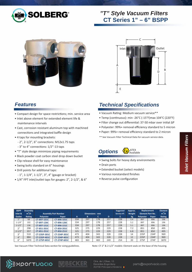
”T” Style Vacuum Filters CT Series 1” – 6” BSPP
Pg. 4-9 www.solbergmfg.com • [email protected] • Tel: +1 630 616 4900 • Fax: +1 630 773 2643
See Vacuum Filter Technical Data sec on for sizing guidelines.
Inle
t Vac
uum
Filt
ers
ATEX Available
• Compact design for space restric ons; min. service area • Inlet above element for extended element life &
maintenance intervals • Cast, corrosion resistant aluminum top with machined
connec ons and integrated baffle design • 4 taps for moun ng brackets: - 2”, 2-1/2”, 6” connec ons: M12x1.75 taps - 3” to 4” connec ons: 1/2”-13 taps • ”T” style design minimizes piping requirements • Black powder coat carbon steel drop down bucket • Clip release shell for easy maintenance • Swing bolts standard on 6” housings • Drill points for addi onal taps: - 1”, 1-1/4”, 1-1/2”, 3”, 4” (gauge or bracket) • 1/4” FPT inlet/outlet taps for gauges: 2”, 2-1/2”, & 6”
Features
A
C
Outlet Inlet
B
E
D
Options
• Vacuum Ra ng: Medium vacuum service** • Temp (con nuous): min -26°C (-15°F)max 104°C (220°F) • Filter change out differen al: 37-50 mbar over ini al ΔP • Polyester: 99%+ removal efficiency standard to 5 micron • Paper: 99%+ removal efficiency standard to 2 micron
Technical Specifications
• Swing bolts for heavy duty environments • Drain ports • Extended bucket (select models) • Various nonstandard finishes • Reverse pulse configura on
** See Vacuum Filter Technical Data for vacuum service data.
Note: CT 2” & 2-1/2” models: Element seals on the base of the housing.
Note: Model offerings & design parameters may change without no ce. Contact Solberg for CAD drawings or see www.solbergmfg.com.
BSPP Assembly Suggested Approx. ElementInlet & m3/h Service HT. Weight m3/hOutlet Rating Polyester Paper A B C D E kg Polyester Paper Rating
1" 68 CT-897-101C CT-896-101C 334 297 178 257 228 5.4 897 896 1961-1/4" 102 CT-897-126C CT-896-126C 334 297 178 257 228 5.2 897 896 1961-1/2" 136 CT-897-151C CT-896-151C 334 297 178 257 228 5.1 897 896 196
2" 298 CT-851-201C CT-850-201C 325 275 229 229 228 7.2 851 850 4952-1/2" 357 CT-851-251C CT-850-251C 325 275 229 229 228 6.8 851 850 495
3" 510 CT-235P-301C CT-234P-301C 473 404 343 328 228 14 235P 234P 9694" 884 CT-235P-401C CT-234P-401C 473 404 343 328 228 12 235P 234P 9696" 1870 CT-275P-601C CT-274P-601C 483 363 483 249 254 20 275P 274P 1870
ReplacementElement Part No.Assembly Part Number Dimensions - mm

Pg. 4-10 www.solbergmfg.com • [email protected] • Tel: +1 630 616 4900 • Fax: +1 630 773 2643
Inle
t Vac
uum
Filt
ers
Features
Options
• Vacuum Ra ng: Medium vacuum service** • Temp (con nuous): min -26°C (-15°F) max 104°C (220°F) • Filter change out differen al: 37-50 mbar over ini al Δ P • Polyester: 99%+ removal efficiency standard to 5 micron • Paper: 99%+ removal efficiency standard to 2 micron
Technical Specifications
• Swing bolts for heavy duty environments • Drain ports • Spool piece extender (select models) • Reverse pulse configura on
A
C
Outlet Inlet
B
E
D
** See Vacuum Filter Technical Data for vacuum service data.
• Compact design for space restric ons; min. service area • Inlet above element for extended element life &
maintenance intervals • Cast, corrosion resistant aluminum top with machined
connec ons and integrated baffle design • 4 taps for moun ng brackets: - 2” to 2-1/2” connec ons: M12x1.75 taps - 3” to 4” connec ons: 1/2”-13 taps • ”T” style design minimizes piping requirements • Bucket made from sha er resistant polycarbonate • Clip release shell for easy maintenance • Swing bolts standard on 6” housings • Drill points for addi onal taps: - 1”, 1-1/4”, 1-1/2”, 3”, 4” (gauge or bracket) • 1/4” FPT inlet/outlet taps for gauges: 2”, 2-1/2”
Note: Model offerings & design parameters may change without no ce. Contact Solberg for CAD drawings or see www.solbergmfg.com.
See Vacuum Filter Technical Data sec on for sizing guidelines.
See-Through Vacuum Filters ST Series 1”–4” BSPP
BSPP Assembly Suggested Approx. ElementInlet & m3/h Service HT. Weight m3/hOutlet Rating Polyester Paper A B C D E kg Polyester Paper Rating
1" 68 ST-897-101C ST-896-101C 340 303 178 264 228 5.0 897 896 1961-1/4" 102 ST-897-126C ST-896-126C 340 303 178 264 228 4.7 897 896 1961-1/2" 136 ST-897-151C ST-896-151C 340 303 178 264 228 4.6 897 896 196
2" 298 ST-851/1-201C ST-850/1-201C 413 362 229 315 228 7.2 851/1 850/1 4952-1/2" 357 ST-851/1-251C ST-850/1-251C 413 362 229 315 228 6.8 851/1 850/1 495
3" 510 ST-235P-301C ST-234P-301C 502 432 343 356 228 13 235P 234P 9694" 884 ST-235P-401C ST-234P-401C 502 432 343 356 228 11 235P 234P 969
ReplacementAssembly Part Number Element Part No.Dimensions - mm

Pg. 4-11
Note: Model offerings & design parameters may change without no ce. Contact Solberg for CAD drawings or see www.solbergmfg.com.
www.solbergmfg.com • [email protected] • Tel: +1 630 616 4900 • Fax: +1 630 773 2643
• SpinMeisters™ available in polished Aluminum • Larger systems available • Various media • Spool piece extender (select models) • Pressure drop gauge • Carbon steel bucket versions
Options
Operating Principle • Centrifugal force from intake air causes par culate to separate from air stream, forcing it to the outer cover perimeter and out through the discharge port • SpinMeister™ Precleaner eliminates large objects
from entering air stream • The air stream then enters the inlet filter and is filtered by a 99+% efficient pleated element
• Vacuum Ra ng: Coarse vacuum service** • Temp (con nuous): min -26°C (-15°F) max 104°C (220°F) • Filter change out differen al: 37-50 mbar over ini al Δ P • Polyester: 99%+ removal efficiency standard to 5 micron • Paper: 99%+ removal efficiency standard to 2 micron **See Vacuum Filter Technical Data for Vacuum Service Data.
Technical Specifications
See Vacuum Filter Technical Data sec on for sizing guidelines. * Denotes housings with carbon steel buckets
• Extreme duty filtra on for high dust environments • Excellent removal for short fibers • Significantly increases life of filter element • SpinMeister™ Precleaner - 85+% efficient up to 15 microns
- Durable molded fiber filled composite material - Pressure drop reduced compared to typ. precleaners
• Bucket made from sha er resistant polycarbonate • Large dirt holding capacity • Clip release band for easy maintenance
Features
A
C
Outlet Inlet
B
E
D
Inle
t Vac
uum
Filt
ers
Extreme Duty Filtration SpinMeister™ ST Series
BSPP Suggested ElementInlet & Range w/ with Polyester Paper Dimensions - mm Service Area m3/hOutlet SpinMeister Element Element Element A B C D E Polyester Paper Rating
2" 68-187 298 ST-SML235-201C ST-851/1-201C ST-850/1-201C 413 362 229 315 228 851/1 850/1 4952-1/2" 68-188 357 ST-SML235-251C ST-851/1-251C ST-850/1-251C 413 362 229 315 228 851/1 850/1 495
3" 170-340 510 ST-SML345-301C ST-235P-301C ST-234P-301C 502 432 343 356 228 235P 234P 9693" 340-765 510 ST-SML445-301C ST-235P-301C ST-234P-301C 502 432 343 356 228 235P 234P 9694" 170-340 884 ST-SML345-401C ST-235P-401C ST-234P-401C 502 432 343 356 228 235P 234P 9694" 340-765 884 ST-SML445-401C ST-235P-401C ST-234P-401C 502 432 343 356 228 235P 234P 9696" 765-1530 1870 CTD-SM6-601C** CT-275P-601C* CT-274P-601C* 645 546 483 432 254 275P 274P 1870
m³/h Rating ReplacementElement Part No.
Assembly Part Number
SpinMeister

Vacuum Filters for Medical Facilities HV Series 1” – 4” BSPP
Pg. 4-12 www.solbergmfg.com • [email protected] • Tel: +1 630 616 4900 • Fax: +1 630 773 2643
Inle
t Vac
uum
Filt
ers
Inlet vacuum filters used in medical facili es’ work areas prevents damage to vacuum pumps and protects the work area environment from harmful contaminates. They are designed for the removal of liquids, solids, and sub-micron par cles. These high efficiency inlet vacuum filters are specifically designed for medical vacuum service on atmospheric air applica ons and can be used on a variety of vacuum pumps in most laboratory and hospital environments.
Industry Need
Options
• Designed specifically for use in laboratory and hospital work area environments
• Vacuum Pumps & Vacuum Systems
Series Specific Application
• H14 UL media - 99.97% @ 0.1 micron - Low air to media ra o minimizes pressure loss for
op mal pump performance - High dirt holding capacity
• Vacuum Ra ng: Medium vacuum service** • Corrosion resistant cast aluminum head with integrated baffle • “E.R” pressure drop indicator gauge; this “Easy
Read” gauge provides color coordinated pressure drop readings
• See-through bucket made from sha er resistant polycarbonate material
• Brass valve and fi ngs for contaminated liquid release • Easy removable & serviceable sterilizable glass flask • Biohazard label included • Cer fica on: Contact factory **See Vacuum Filter Technical Data for Vacuum Service Data.
Features • Vacuum filter systems • Support stand and protec ve shroud • Carbon steel bucket for severe duty applica ons • Oxygen rich systems-contact factory for specialized construc on requirements • Larger configura ons, contact factory
Contact factory for dimensions.
Note: Model offerings & design parameters may change without no ce. Contact Solberg for CAD drawings or see www.solbergmfg.com.
BSPP Assembly Approx. ReplacementInlet & m3/h Assembly Weight ElementOutlet Rating Part Number kg Part No.
1" 70 HV-UL896-101C 7 UL8961-1/4" 70 HV-UL896-126C 6 UL8961-1/2" 70 HV-UL896-151C 6 UL896
2" 175 HV-UL850/1-201C 9 UL850/12-1/2" 175 HV-UL850/1-251C 8 UL850/1
3" 340 HV-UL234/2-301C 15 UL234/24" 340 HV-UL234/2-401C 13 UL234/2

Pg. 4-13
Note: Model offerings & design parameters may change without no ce. Contact Solberg for CAD drawings or see www.solbergmfg.com.
www.solbergmfg.com • [email protected] • Tel: +1 630 616 4900 • Fax: +1 630 773 2643
• Float level port/switch • Cast head protec ve coa ngs • Heavy duty carbon steel buckets available • Clamp style swing bolts on 1” to 2-1/2” • Spool piece extender on select models • Drain systems compliant (See page 4-21) • Pressure drop gauge
Options
Operating Principle • Inlet air with poten ally harmful liquid and large par culate enters the housing and is separated by a baffling mechanism and direc onal air flow changes. • The larger par cles and liquid drops down and collects at the bo om of the separator. • The float bullet within the separator screen rises with the liquid level un l max capacity and limits the flow thereby protec ng the pump from damage.
Features
Dimension tolerance + 6 mm
• Minimize the likelihood of liquid and debris from damaging vacuum valves and pumps • Easy visual inspec on with see-through housing • Reduce piping costs with “T” style configura on • Compact design for space restricted work areas
Benefits
A
C
Outlet Inlet
B
E
D
• Vacuum Ra ng: Medium vacuum service** • Bucket made from sha er resistant polycarbonate • Corrosion resistant cast aluminum head w/knock-out baffle • Stainless steel float capsule for emergency shut off • Stainless steel perforated float tube (SS expanded metal float tube on 1” - 1-1/2”) • Clamp style swing bolts on 3” & 4” standard • Temperature ra ngs: max 104°C (220°F) • 1/4"BSPP drain (1" to 1-1/2"), 1/2" drain (2" to 4") • Drill points for addi onal taps: - 1”, 1-1/4”, 1-1/2”, 3”, 4” (gauge or bracket) • 1/4” FPT inlet/outlet taps for gauges: 2”, 2-1/2”
Inle
t Vac
uum
Filt
ers
See -Through Liquid Separators STS Series 1 - 4” BSPP
** See Vacuum Filter Technical Data for vacuum service data.
BSPP Assembly Suggested HoldingInlet & m3/h Assembly Dimensions - mm Service HT. CapacityOutlet Rating Part Number A B C D E (liter)
1" 68 STS-101C 362 325 178 285 228 1.61-1/4" 102 STS-126C 362 325 178 285 228 1.61-1/2" 136 STS-151C 362 325 178 285 228 1.6
2" 297 STS-201C 438 388 229 342 228 3.72-1/2" 356 STS-251C 438 388 229 342 228 3.7
3" 510 STS-301C 522 454 343 378 228 5.74" 850 STS-401C 522 454 343 378 228 5.7

Pg. 4-14
Typical LRS Configura on
www.solbergmfg.com • [email protected] • Tel: +1 630 616 4900 • Fax: +1 630 773 2643
LRS Series Specifications
• Mul ple stage filtra on: - Integrated baffle - 99+% efficient polyester par culate filter element • For aerosol apps, addi onal knock out pot or separator is unnecessary • Compact construc on design
SRS Series Specifications
• Mul ple stage filtra on - Integrated baffle - Preseperator wire mesh element (Stainless steel construc on recommended) - 99+% efficient polyester par culate filter element • Addi onal knock out pot or separator unnecessary • Significant liquid/slurry holding capacity • Removable base op on for easy access cleaning • Brackets for support legs & nameplate • Li ing lugs
Operating Principle
• The inlet air with poten ally harmful liquids and par culate enters the highly efficient vacuum filter and is separated by a baffling system.
• The larger par cles and liquid drop down to the large capacity lower chamber.
• The lower chamber has significant liquid/slurry holding capacity and has a removable base for easy cleaning.
• The final stage has a replaceable filter element for par culate that is 99+% efficient before it reaches the vacuum pump.
Note: A typical SRS Series design has a preseperator before the filter element for addi onal liquid/par culate removal.
A
C
Outlet
Inlet
D
B
Inle
t Vac
uum
Filt
ers
Liquid Separator/Vacuum Filter LRS Series, SRS Series
SRS with Preseperator Element
Inlet
Outlet
Preseperator Element
Integrated Baffle
Removable Bo om
SRS with Preseperator Demister Op on
Preseperator Demister

• Corrosive resistant carbon steel construc on • Blue epoxy coa ng • Baffle system • 1/4” inlet/outlet taps (select models) • 1” drain port and sight port • Wide range of opera on flows
Features • PED, ASME rated vessels • Stainless steel construc on & nonstandard finishes • Nonstandard filter media • Extended bucket for addi onal holding capacity • Preseperator stainless steel demister • Stainless steel wire mesh preseperator element: (Stainless steel construc on recommended) • Safety switch port for high liquid warning • Drain systems compliant (See page 4-21) • Support legs, li ing lugs, vacuum gauges
Options
• Vacuum Ra ng: Medium vacuum service** • Filter change out differen al: 37-50 mbar over ini al ΔP • Polyester: 99%+ removal efficiency standard to 5 micron **See Vacuum Filter Technical Data for vacuum service data.
Technical Specifications
Liquid Separator/Vacuum Filter LRS Series, SRS Series
Pg. 4-15 www.solbergmfg.com • [email protected] • Tel: +1 630 616 4900 • Fax: +1 630 773 2643
LRS Series
SRS Series (Contact factory for details. Stainless steel configura ons available.)
• Simplified vacuum package: 2 func ons in 1 (liquid separator & inlet air filter) • High efficiency separa on & mul stage filtra on • Protects pump from harmful liquids that breaks down lubrica ng/sealing oil • Lower costs from unnecessary piping • Significant liquid/slurry holding capacity • Prevents emulsifica on of oil in oil lubricated systems • Reduce footprint with compact design
Benefits
B.C. O.D.
B.H.
O.D.: Outside Diameter B.C.: Bolt Circle B.H.: Bolt Hole
All flanges are orientated “split center”. Note: Model offerings & design parameters may change without no ce. Contact Solberg for CAD drawings or see www.solbergmfg.com.
See Vacuum Filter Technical Data sec on for sizing guidelines. In
let V
acuu
m F
ilter
s
ATEX Available
PN10 Dimensions - mm No. of ThicknessPattern Flange O.D. B.C. B.H. Holes Flg mm
DN100 220 180 18 8 20DN150 285 240 22 8 22DN200 340 295 22 8 24DN250 395 350 22 12 26DN300 445 400 22 12 26
Assembly Flange Reference Only Approx Replacementm3/h Inlet & Assembly Holding Element
Rating Outlet Part Number Capacity L Part No.1869 DN150 SRS-377/274S-DN150 76 377/274S3058 DN200 SRS-385/376S-DN200 170 385/376S4162 DN250 SRS-385/384S-DN250 170 385/384S5606 DN250 SRS-485/384S-DN250 300 485/384S7475 DN300 SRS-485/384S-DN300 300 485/384S
Assembly Inlet / Inlet / Approx. Replacement Elementm3/h Outlet Outlet Assembly Holding Element m3/h
Rating Size Type Part Number A B C D Capacity L Part No. Rating105 3/4" NPSC LRS-19-075HC 451 112 195 84 5.7 19 170145 1" BSPP LRS-19-101HC 455 117 195 89 5.7 19 170145 1 1/4" BSPP LRS-19-126HC 455 117 195 89 5.7 19 170170 1 1/2" BSPP LRS-19-151HC 455 118 195 90 5.7 19 170230 2" BSPP LRS-237-201HC 564 171 305 168 9.5 237 935335 2 1/2" BSPP LRS-237-251HC 618 226 305 222 9.5 237 935510 3" BSPP LRS-237-301HC 618 226 305 222 9.5 237 935885 DN100 FLG LRS-275-DN100 594 292 406 203 17 275 1870
1415 DN150 FLG LRS-275-DN150 1032 305 406 229 17 275 1870
Dimensions - mm
Pg. 4-16 www.solbergmfg.com • [email protected] • Tel: +1 630 616 4900 • Fax: +1 630 773 2643
Inle
t Vac
uum
Filt
ers
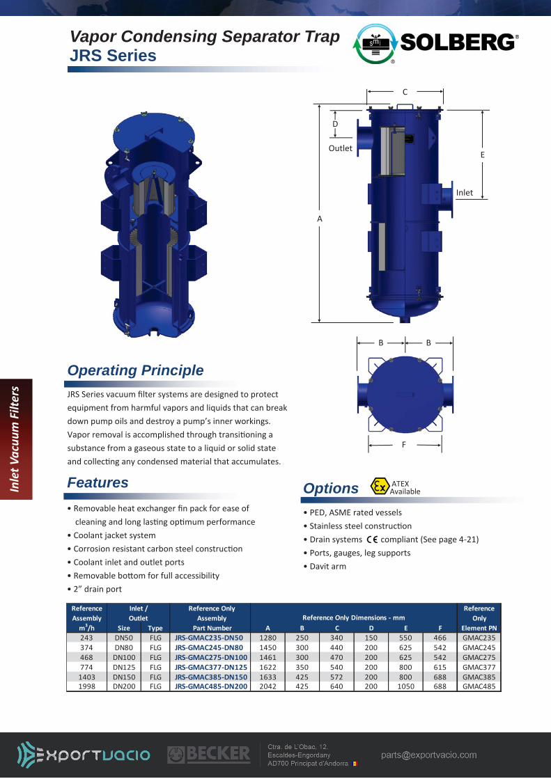
Vapor Condensing Separator Trap JRS Series
Operating Principle
Options • PED, ASME rated vessels • Stainless steel construc on • Drain systems compliant (See page 4-21) • Ports, gauges, leg supports • Davit arm
• Removable heat exchanger fin pack for ease of cleaning and long las ng op mum performance
• Coolant jacket system • Corrosion resistant carbon steel construc on • Coolant inlet and outlet ports • Removable bo om for full accessibility • 2” drain port
Features
JRS Series vacuum filter systems are designed to protect equipment from harmful vapors and liquids that can break down pump oils and destroy a pump’s inner workings. Vapor removal is accomplished through transi oning a substance from a gaseous state to a liquid or solid state and collec ng any condensed material that accumulates.
Note: Model offerings & design parameters may change without no ce. Contact Solberg for CAD drawings or see www.solbergmfg.com.
ATEX Available
Reference Reference Only ReferenceAssembly Assembly Only
m3/h Size Type Part Number A B C D E F Element PN243 DN50 FLG JRS-GMAC235-DN50 1280 250 340 150 550 466 GMAC235374 DN80 FLG JRS-GMAC245-DN80 1450 300 440 200 625 542 GMAC245468 DN100 FLG JRS-GMAC275-DN100 1461 300 470 200 625 542 GMAC275774 DN125 FLG JRS-GMAC377-DN125 1622 350 540 200 800 615 GMAC377
1403 DN150 FLG JRS-GMAC385-DN150 1633 425 572 200 800 688 GMAC3851998 DN200 FLG JRS-GMAC485-DN200 2042 425 640 200 1050 688 GMAC485
Reference Only Dimensions - mmInlet /Outlet
C
A
Outlet
Inlet
B
D
B
F
E

Pg. 4-17 www.solbergmfg.com • [email protected] • Tel: +1 630 616 4900 • Fax: +1 630 773 2643
Inle
t Vac
uum
Filt
ers
Vapor Condensing Separator Trap Compact JST/JCT Series
Operating Principle
Options • ATEX available for JCT versions only • Addi onal ports • Vacuum gauge • Support frame • Drain systems compliant (See page 4-21) • Spool piece/Extended bucket (select models/sizes)
Features JST & JCT Series vapor condensers are designed to protect equipment from harmful vapors and liquids that can break down pump oils and harms a pump’s inner workings. Vapor removal is accomplished through transi oning a substance from a gaseous state to a liquid or solid state and collec ng any condensed material that accumulates.
E
A
C
Outlet Inlet
B D
ATEX Available
Note: Model offerings & design parameters may change without no ce. Contact Solberg for CAD drawings or see www.solbergmfg.com.
See-Through Housing
BSPP Assembly
Inlet & Part Number
Outlet A B C D
2" JST-C2048-201C 445 380 229 3342-1/2" JST-C2048-251C 445 380 229 334
3" JST-C2081-301C 537 454 343 3784" JST-C2081-401C 537 454 343 378
Reference Dimensions - mm
Black Carbon Steel Housing
2" JCT-C2048-201C 413 364 229 3182-1/2" JCT-C2048-251C 413 364 229 318
3" JCT-C2081-301C 656 571 343 4954" JCT-C2081-401C 656 571 343 4956" JCT-C3226-601C 757 646 483 532
• Removable heat exchanger fin pack for ease of cleaning and long las ng op mum performance
• Coolant jacket system • Stainless steel demister pad • Compact housing for minimal footprint • Removable bo om for full accessibility • Coolant inlet and outlet ports • JST Series: - Durable see-through bucket made from sha er resistant polycarbonate - 1/2” drain port • JCT Series: - Corrosive resistant carbon steel bucket - 1” drain port • Contact Solberg for flow rates for your specific applica on

Pg. 4-18 www.solbergmfg.com • [email protected] • Tel: +1 630 616 4900 • Fax: +1 630 773 2643
Natural Gas Filtration Suction/Interstage Scrubbers
Features
Options
• Protects equipment from condensate, oil, and par culate entrained in the gas stream • Mul -stage separa on - 316 SS vane pack and/or demister pad for heavy condensate and oil removal - High efficiency 99+% final filter elements • Corrosion resistant carbon steel construc on • Contact factory for model offering and availability
Special standards: PED, ATEX, ASME Vessel code sec. VIII division I Stainless steel construc on Special coa ngs or finishes Replaceable filter elements in various media for par culate removal Gauge ports, float switches Custom leg supports Flush port for vessel cleaning Davit arm for vessel lid removal
Note: Model offerings & design parameters may change without no ce. Contact Solberg for CAD drawings or see www.solbergmfg.com.
Series Specific Applications • Landfill and Bio-Gas recovery • Fuel for reciproca ng engines and gas turbines • Gas compression • Compressor packages - Rotary Screw - Centrifugal - Reciproca ng - Vane
Note: Drawings are shown with sample configura on and dimensions only.
Inle
t Vac
uum
Filt
ers
ATEX Available

Pg. 4-19 www.solbergmfg.com • [email protected] • Tel: +1 630 616 4900 • Fax: +1 630 773 2643
Inle
t Vac
uum
Filt
ers
Vacuum Filters for Solar, Semi-Con, LED, Coating
Features
Note: Model offerings & design parameters may change without no ce. Contact Solberg for CAD drawings or see www.solbergmfg.com.
• Integrated reverse pulse technology unloads and extends filter life; improving maintenance intervals and process run me • Safeguard pumps from harmful par cles (SiOx, GAN, etc.) • Prevents par cles from contamina ng pump oil • Prevents build up and seizing in dry pumps • Integrated support stand • Removable base for easy cleaning access • Carbon steel or stainless steel housing construc on
• Configured and custom designs • Nonstandard finishes • PTFE media: Temp (con nuous): 104°C (220°F) • Dutch Twill media: Temp (con nuous): 190°C(375°F) • ASME, PED rated vessels • Parallel filtra on systems • Valves for semi or fully automated system opera on • Vacuum Leak Ra ng: 1x10⁻⁸ mbar l/sec • Contact factory for model offering and availability
Options • Vacuum Leak Rate: 1x10⁻⁵ mbar l/sec • Vacuum Ra ng: Medium vacuum service** • Face Velocity @ .10 m/sec (20 /min) **See Vacuum Filter Technical Data for Vacuum Service Data.
Technical Specifications
• Extends filter life improving maintenance intervals and process run me • High conductance design • Lower costs from unnecessary piping • Large liquid/slurry holding capacity • Easy maintenance (removable base) • Reduced footprint
Benefits
Operating Principle
• Reverse pulse technology extends maintenance intervals and improves process produc vity by rapidly introducing atmospheric air or inert gas into the system. • This process purges dust from loaded filters and allows the par cles to se le in the bo om chamber for easy disposal.
• Vacuum furnaces for crystal growing, steel, tanium, etc. • Vacuum coa ng and lamina on • Wet & dry vacuum pumps & systems • Compa ble with most dopants • Backstreaming
Series Specific Applications
Reverse Pulse Filter: RX Series
Pg. 4-20 www.solbergmfg.com • [email protected] • Tel: +1 630 616 4900 • Fax: +1 630 773 2643
Inle
t Vac
uum
Filt
ers
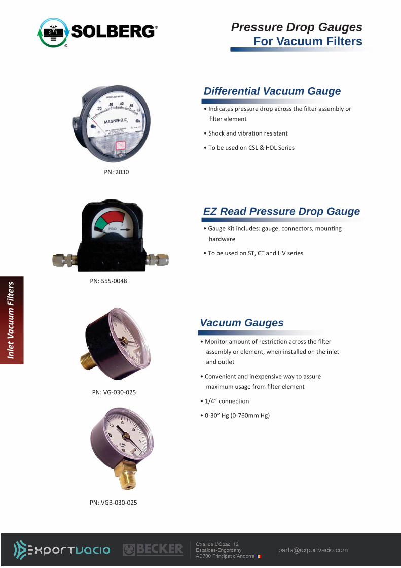
Pressure Drop Gauges For Vacuum Filters
Note: Model offerings & design parameters may change without no ce. Contact Solberg for CAD drawings or see www.solbergmfg.com.
EZ Read Pressure Drop Gauge
• Indicates pressure drop across the filter assembly or filter element
• Shock and vibra on resistant
• To be used on CSL & HDL Series
Differential Vacuum Gauge
• Gauge Kit includes: gauge, connectors, moun ng hardware
• To be used on ST, CT and HV series
• Monitor amount of restric on across the filter assembly or element, when installed on the inlet and outlet
• Convenient and inexpensive way to assure maximum usage from filter element
• 1/4” connec on
• 0-30” Hg (0-760mm Hg)
Vacuum Gauges
PN: VG-030-025
PN: 2030
PN: 555-0048
PN: VGB-030-025

www.solbergmfg.com • [email protected] • Tel: +1 630 616 4900 • Fax: +1 630 773 2643
Note: Model offerings & design parameters may change without no ce. Contact Solberg for CAD drawings or see www.solbergmfg.com.
Pg. 4-21
Operating Principle
Options
Stainless steel construc on (304,316) Stainless steel solenoid valves Electrical box according to EN 60204-1 Filter silencer for bleed valve Extra high level switch
Features
The Automa c Drain System allows Solberg Liquid Separator units to be drained without stopping the process and breaking the vacuum. The liquid removed by the liquid separator flows under gravity into the drain pot. When the high level switch triggers, the drain pot is isolated from the liquid separator by the upper solenoid valve. The vacuum break valve then opens along with the bo om drain valve allowing the liquid to drain to atmosphere. Once the lower level switch opens the drain valve and vacuum break close, the upper solenoid valve opens and the process repeats.
Capacity of 2, 5 and 10 liters available Durable carbon steel construc on Stainless steel coa ng Magne c float switch in stainless steel with electrical plug connec on Bracket for 5 and 10 liters drain pot to support the system on a frame or a wall 2/2 ways diaphragm valves with solenoid system 230 VAC , brass and NBR-K seat seal
Holding BSPPCapacity Inlet & Weight
(liter) Outlet Carbon Steel (SS Coating) 304SS A B C D E kg2 1/2" DSE-L002-050HC DSE-L002-050HCS1 522 146 71 - - 5.55 1" DSE-L005-101HC DSE-L005-101HCS1 580 166 122 286 254 1010 1" DSE-L010-101HC DSE-L010-101HCS1 652 217 182 286 254 16.510 2" DSE-L010-201HC DSE-L010-201HCS1 785 217 182 286 254 26
AssemblyPart Number Dimensions - mm
Automatic Drain System for STS, LRS, SRS, JST, JRS
Inle
t Vac
uum
Filt
ers

Pg. 4-21 www.solbergmfg.com • [email protected] • Tel: +1 630 616 4900 • Fax: +1 630 773 2643
Inle
t Vac
uum
Filt
ers