inova 3rd and 4th channel docs
TRANSCRIPT

VARIAN
Pub. No.01-999135-00. Rev. 80599
iF
Srd and 4th RFChannel PackagesInstallation
0vervierv, this page
Saf'ety Precautiorts, this ;:age
Requirenrents, pag* 2
Parts l.ist, page 2
Instailation Procedure, page 2
Powering IJp, Configuring, and Testing.pag*7
RF Chamrel Iiiterchange Moclule, page 9
Schenratic l)rawings, page 9
OverviewVarian's 3rd and 4thrf channel packages add new, independent rf transmitter channels touNrrYlNOyA or UNITYp/zs NMR spectrometer systems. The packages differ depending onthe proton frequency of the spectrometer, whether the channels are broadband or fullband,and whether the package is for 3rd channel only or for both 3rd and 4th channels. Packagescovered in this manual include Part Nos. 00-993450-00, 00-993451-00, 00-993452-00, 00-993453-00,0A-993455-00, 00-993457 -00, 00-993459-00,00-993462-00, 00-993463-00,00-993465-00, and 00-993465-04. This manual also covers installation of the RF ChannelInterchange Module, Part Nos. 0l-904799-XX.
Safety Precautions
CAUTION: Only qualified maintenance personnel shall remove equipmentcovers or make internal adjustments. The system containsdelicate components that can be easily damaged. Before workinginside a cabinet, turn off the main system power switch located on
al-999135-04 80599 Srd and 4tlt RF Channel lnstallation

Srd and 4th nF Channel Packages
the back of the console. Take electrostatic discharge (ESD)precautions to avoid damage to sensitive electronic components.
RequirementsuNrrYlNOyA or UNITYp/r.rs NMR spectrometer system.
Parts ListThe following parts are required to install the packages:
' AMT amplifier kit, which, depending on the channel configuration specified on theorder, includes:
o AMT amplifier
. Cables, relays, attenuators, and hardware. PTS frequency synthesizer kit, which includes:
. PTS frequency synthesizer
o Connector board
o Power cord, coax cables, and hardware. Nth Channel kit (Part No. 00-992951-00), which includes:
. Transmitter and Controller boards
. Coax cables and hardware
o Attenuator board. 3rd channel or 4th channel
Installation ProcedureInstallation involves preparing to install the hardware; installing the PTS frequencysynthesizer, fransmitter board, ffansmitter controller board, pulse amplifier, and switchingrelays (if applicable); and then configuring and testing the system.
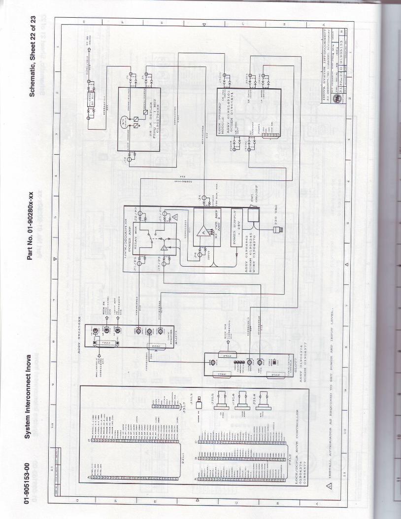
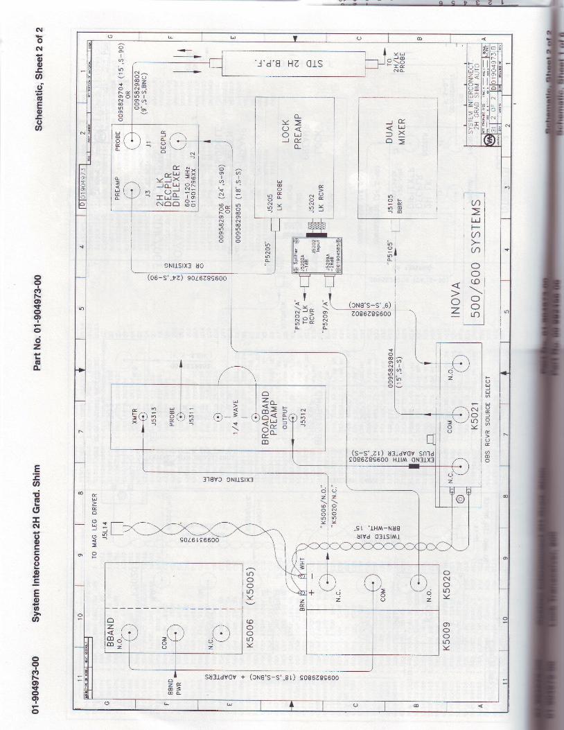
For parts layout, wiring diagrams, and various optional configurations, refer to the systeminterconnect schematic drawing (Pub. No. 01-903010-00 for uNrrYlNOuA, or Pub. No.87- 1 9590 1 -00 for tINITYp/as).
Preparing to Install the Hardware
1. Stop the acquisition process in the host computer (in a shell window enter thecommand su acg)roc, or become root and enter kilLacg>roc) and turn offthe cabinet power supply. Remove the cabinet's power cable from the connector atthe rear of the power supply.
2. Remove the rear and side cabinet panels and front doors, as necessary.
2 3rd and 4th RF Channet lnstaltation 01-999135-00 80599

Srd and 4th RF Channel Packages
Installing the PTS Synthesizer
1. Remove the blank panel above the existing synthesizer. Remove the moving parts of
two chassis slides from the cabinet position where the synthesizer is to be mounted.
This is usually the position immediately above the existing synthesizers.
2. Attach the slide parts to the new synthesizer using four 8-32 screws and slide shims
(00-993161-00).
3. Attach rhe PTS Connector board (00-992106-00) to the Remote Control input
connector at the rear of synthesizer.
4. Set switches on the PTS Connector board:
. For channel 3, set positions 3 of SW1 and SW2 on and all other positions off.
. For channel4, set positions 4 of SW1 and SW2 on and all other positions off.
5. Connect the overrange cable (00-993015-00), if supplied, between P9 on the PTS
Connector board and the 9-pin D connector at the rear of the synthesizer.
6. Make sure the INT. STDIEXT. STD switch on the synthesizer is set to the EXT. STD
position.
1. Mount the synthesizer in the cabinet. Install four cage nuts (23-101008-00) at
appropriate places in the cabinet's rack mounting rail so that the synthesizer can be
secured with the four screws (23-101009-00) provided.
8. Connect a free Frequency Bus ribbon cable connector to the PTS Connector board
at the rear of the new synthesizer.
g. Connect the supplied power cable between the synthesizer's input connector and the
cabinet's power strip (at center rear of the cabinet)-
10. Connectthe shortcoaxial cable (00-958297-0x) between the synthesizer's 5/10MHz
IN connector and an unused connector at the signal splitter assembly located at the
upper rear of the cabinet, behind the synthesizers.
11. Connect a long coaxial cable (00-958298-11) to the synthesizer's MAIN OUTPUT
connector. Route this cable through the cable tray below the rf cardcage (upper
cardcage), through the hole below the cardcage, and to the front of the cardcage. This
will connectto J2X4 on the Transmitter board that will be installed later.
tnstalling Transmitter and Transmitter Controller Boards
Refer to Figure l, Figure 2, and Figure 3 for cable diagram an slot assignments foruNlrY/NOyA and UNITYpIus rf control cardcage and rf cardcage.
1. Remove blank panels as necessary from the two cardcages.
Refer to Figure .l for rf control cardcage front view and to Figure 2 and Figure 3 for
rf cardcage rear and front views, respectively'
Transmitter 3 and Transmitter Controller 3 go into slot 7 of the rf cardcage and slot
15 of the rf control cardcage, respectively. Transmrtter 4 and Transmitter Controller
4 go into slot 6 of the rf cardcage and slot 13 of the rf control cardcage, respectively.
Cardcage slots are numbered from the left as viewed from the front.
2. Connect, at the rear of the rf cardcage, a thin yellow coaxial cable (00-993198-03)
that will carry the reference frequency from the Reference Generator board (00-
992096-0D to the new Transmitter board.
01-999135-00 80599 Srd and 4th RF Channellnstaltation 3

EodoI
SlotI
llod
o-
Slot3
-9o
ooo.zoou,cG'
!C)o
Slot
oGoEool<(t-9ooUgocooo.=oIoE
Slot1 1
=(E
oCLo
\f
(5l!=
Slot1 2
=f
goEooo.Ett,
(g
F
Slot1 3
=tgtroEIo
ao(5L=
Slot1 4
6D
-goEooo.Eotr(E
Slot1 5
-6
oCLo
C\I
ol!=
Slol1 6
6l
-9og
ooo'Eatr(g
Slot1 7
-(Eco
CLo
oll=
Slot1 8
go
ooo.Eto
o
Slot1 9
oJoEodCLE
Slot20
oo(uEo
5oUct)o
oE t(E=
Slot2 1
llJtr
o.o
It ltlL]
J201
Slot1
J202
tlt ltlL]
Srd and 4th RF Channel Packages
Figure L. RF Control Cardcage, Front View, Showing Slot Assignments
TransmitterController 3
Figure 2. RF Cardcage, Rear View, Showing Ribbon Cable Connections
X1Power
&Groundtrdqp o o lpoot
,1200
'floIt ltlII5
J231Slot4
J232:* fi;* HHfl#t \.
att I
ITo
ReceiverController
HIi:ll I
i f t \ lt t t l
i!.t-l I I
l l l
lITo
TransmitterController 4
J221Slot3
J222
o
oa)oc(l,
FJoo
01-999135-0A 805993rd and 4th RF Channel lnstallation

E(ECLo
Slot1
o(!
oc0)(,oC)g
E(t,o(E
Slot2
o
(l)()otr(E
l<()o
Slot3
G)(uCLU'
Slol4
o'6()oE
Slot5
<f
().=EaEGI
F
Sloto
c?
C).=EoEc'
Slot7
ol
o.=Ean
E
Sloi8
C,EEoc(E
Slot9
-c()'=oo(gfc(l,
Ecg|E
Eosf
e:,
6l
Slot1 0
Srd and 4th RF Channel Packages
Figure 3. RF Cardcage, Front View, Showing Slot Assignments
The coaxial connector snaps into its receptacle but requires a special tool to removeit. Be sure to install the connectors in the proper sockets. Refer to Figure ? showingthe rear view of the rf cardcage.
3. Clip the cable tie and install the one supplied around all cables.
4. Replace the boards that were removed in step 1.
5. Install the new Transmitter board and Transmitter Controller board in theirrespective slots.
6. Reinstall the blank panels in any remaining empty cardcage slots.
CAUTION: The cardcage could overheat if the blank panels are not reinstalledinto the empty cardcage slots.
7 . Set the selector switch on the front of the new Transmitter Controller board toposition 3 for rf channel 3 or 4 for rf channel 4.
8. Connect a small coaxial cable (00-99289J -04, 15 inches long) between one of theempty receptacles at the front of the Receiver Controller & Clock Generator boardand J3X1 at the front of the new Transmitter Controller board.
9. Connect the synthesizer output cable (step 11 on page 3 in "lnstalling ttre li'i'SSyuthesizt:r") to J2X4 of the newly installed transmitter.
10. Remove the input and output coaxial cables from the front panel of the Attenuatorboard in the RF Cardcage. Install the new Attenuator board in the same slot of theRF Cardcage. Replace the input and output cables you just removed.
11. Connect the short coaxial cable (00-958298-03) between J2X3 of the newly installedtransmitter and the channel 3 or channel 4 input connector at the Attenuator board.
12. Connect a long coaxial cable (00-958297-I0,5 feet long) to the appropriate channeloutput from the Attenuator board (see Figure -l). Route the cable under the cage tothe rear of the cabinet where it will later be connected to the pulse amplifier.
al-999135-00 80599 Srd and 4th RF Channellnstallation 5

Srd and 4th RF Channel Packages
ampt14>e='aa l '
amp t14>e= 'aaa '
amp t14>e= 'aa ln '
amptype= 'aa l1 '
I f d f rq2=df rq3,both signals are routedthroush OUT 3.
amp type= 'aaan '3rd Channel
amptype= 'aaaa '
3rd Channel
' - - - - - l O U T 4
Figure 4. Third and Fourth Channel Cable Routing Diagrams
3rd and 4th RF Channel lnstallation 01-999135-00 80599
3rd and 4th nF Channel Packaaes
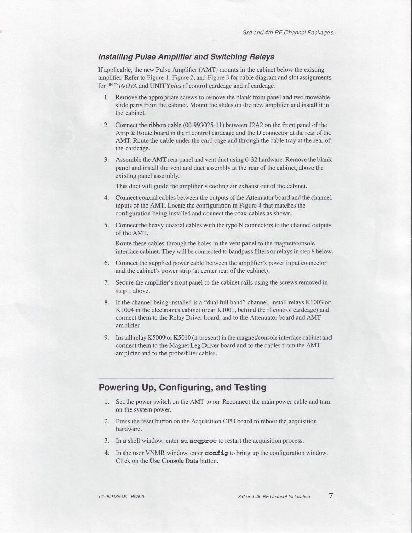
lnstalling Pulse Amplifier and Switching Relays
If applicable, the new Pulse Amplifier (AMT) mounts in the cabinet below the existingamplifier. Refer to Figure [, Figure 2, and Figure 3 for cable diagram and slot assignmentsfs1 ur'{tw1l\y'OVA andUNITYp/as rf control cardcage and rf cardcage.
1. Remove the appropriate screws to remove the blank front panel and two moveableslide parts from the cabinet. Mount the slides on the new amplifier and install it inthe cabinet.
2. Connect the ribbon cable (00-993025-11) between JZAZ on the front panel of theAmp & Route board in the rf control cardcage and the D connector at the rear of theAMT. Route the cable under the card cage and through the cable tray at the rear ofthe cardcage.
3. Assemble the AMT rear panel and vent duct using 6-32hardware. Remove the blankpanel and install the vent and duct assembly at the rear of the cabinet, above theexisting panel assembly.
This duct will guide the amplifier's cooling air exhaust out of the cabinet.
4. Connect coaxial cables between the outputs of the Attenuator board and the channelinputs of the AMT. Locate the configuration in Figure 4 that matches theconfiguration being installed and connect the coax cables as shown.
5. Connect the heavy coaxial cables with the type N connectors to the channel outputsof the AMT.
Route these cables through the holes in the vent panel to the magnet/consoleinterface cabinet. They will be connected to bandpass filters or relays in step I below.
6. Connect the supplied power cable between the amplifier's power input connectorand the cabinet's power strip (at center rear of the cabinet).
7. Secure the amplifier's front panel to the cabinet rails using the screws removed instep 1 above.
8. If the channel being installed is a "dual full band" channel, install relays K1003 orKl004 in the electronics cabinet (near K1001, behind the rf control cardcage) andconnect them to the Relay Driver board, and to the Attenuator board and AMTamplifier.
9. Install relay K5009 or K5010 (if present) in the magnet/console interface cabinet andconnect them to the Magnet Leg Driver board and to the cables from the AMTamplifier and to the probe/filter cables.
Powering Up, Configuring, and Testing1. Set the power switch on the AMT to on. Reconnect the main power cable and turn
on the system power.
2. Press the reset button on the Acquisition CPU board to reboot the acquisitionhardware.
3. In a shell window, enter su acw)roc to restart the acquisition process.
4. In the user VNMR window, enter conf ig to bring up the configuration window.Click on the Use Console Data button.
01-999135-00 80599 Srd and 4th RF Channellnstatlation 7

9rd and 4th RF Channel Packages
The computer interrogates the newly installed hardware to determine itsconfiguration.
5. Pull down the channel Configure: menu and select the channel to be configured-RF Channel 2 @ec), RF Channel 3 (Dec2), or RF Channel4 (Dec3). Verify or setthe parameters listed in Table 1.
Thble 1. CONFIG Labels and Values for 3rd or 4th RF Channel
l^abel Value
Type of RF
Synthesizer
Latching
U+ Direct Synthesis or U+ Hl Only
Select the model number to match the newlv installed unit
Present
Frequency Overrange Select Not Present or Present
Frequency Step Size 0.1 Hz
Coarse Attenuator 79 dB
Upper Limit 49 dB is a good number to start
Fine Attenuator Present
Waveform Generator Not Present or Present
Type of Amplifier Linear Full Band, Linear Low Band, or shared withchannel 3 (4th channel only)
6. Repeat step 5 for the next channel if installed.
7. Select the Exit and Save button in the top panel to enter the values.
8. Test the new rf channel for functionality. Note that none of the experiments will haveappropriate parameters for the third and/or fourth channel until a parameter set isretrieved into that experiment with the rt or rtp command.
9. Recall a parameter set:
rU( ' l v r tn r /s tdpar /H l ' ) dn2= 'C13 ' su
Verify that the output of the installed PTS is l0 dBm.
10. Enter create ( 'dBwrf 2 ' ) set l imi t ( 'dpwr 1r2, ,4095 ,O,L). Note thatif the Waveform Generator board is not installed in the channel being tested, use theparameter dpwrm instead of dpwrf .
1 1. Connect the output of the transmitter to a scope and enter:
dpwr f2=255 rsLL,L023,2047 r4095 d l=5 dm2= 'y ' go
12. Verify that the output voltage changes by 6 dB. When dpwrf 2 =409 5, the outputshould be about 10 dBm.
13. Set dpwrf2=4095 drn2='n' and enter su.
14. Connect the output (see Figure 4) of the AITN/SW to a scope.
15 . Setdm='n ' dm2= 'y ' ( i fp resentdm3= 'n , ) n t= l d1=5dpwr2=l0,20,30,40 (not higher!) and enter go.
Verify that the amplitude increases by l0 dB each time.
16. If the fourth channel is present, repeat steps 10 through 15 to check it.
8 3rd and 4th RF Channet tnstallation 01-999135-00 80599

z0t
!
N
1
f
E
e
B
B!
g 3N
!
N
0!
3 e
!
I
2c0E
2q
0
xzc0
o
zc0E
c
zcn
zc0
zc00!
X
zcn
4Ir1l
ncl0zzt!0d
oI(oo(rl(rl(.t
I
oo
@oo35t-to'rtoof:ooIt
5oqf
!!l-FT
zIo
T(ooNooxIxx
aoo3gt=.-o@
oosit
Cl)
oNCO

DE>
Eri t\)
^ : f
l0 I
P. H
O H
X ? F I
E XN
D
{-1T - f
f"-'l
l : I ll I o ll t N l
o.JI(o
(t(rl-l(rlg)
Ioo
@
oFfo3:Flo!oo:5ooFT
5oql
!It-zIo
I(ooNoox
I
xx
@o:to3!,r!.-o@5oo
{oNg)
a)(\lq-
o(\l(\l,,J
oo.trooE(EEo
,Co3n
xxIx
C'oc\loo)
I
odz+.Lr(go.
G
otq{,(,otrcoe.9EEo
F
oo
ooI
ctlo|F
1|)oot
IF.
o
,-L)lrJ-JlrJU)
lrJ(J
-oaE
C)
an
o
t/)
|JJF(t)
(f)
OO(o
OOLrO
Nolf))<
oz.
oNoLO)<
o,()o1r))<
(s-s' . .2r) ul idvcv sntdt0962896O0 Hll/Y\ 0Nltxl
I
anI
qlf)
rr)o
lno_
(cNe's-s ' , ,0)2086289600
.rto4'o)N@lr)o,c)o
kOtoc\UOo-
)l) E
o c )F ( r
k
C-.1oNtr)0-
3'18VC 9N[StX3
rOOOrr)\l
COO
lr))<
U)I
a -
@
ra)O@(')N€rJ)
o
.<--_-_--__-->
( \ ^ - . - >O r r9 zxi 6-@ aL , Ia a nOo b
(oo-s ' ,p2) 9oL6zs96oo
sol .6 r t6600
toF. O:o oN()tf)ctt()O
Etrl
Eo
H - tJ :. ^ 0
oF
E.trJX
' J ' d . 8 H Z C I S
o_\<O <o L !) E
o-
14,
^o u.U
,., F c.r 9o - o B
f i x f ; x- - - J
5 ,.-'',f; ('-r-o q
E N *
-5H =frrn l - rJ o( .- ^ * J N -
\-/ a
I t *J* 1cnN o o 6 5
L!|ooEL
fL
lfJ
g(L
oo)I
6-
sN
P o <x oo)N€|J.O)O
9NIJS IX ] UO
C!
rO10
o4o-; > t5s -rxH3Eo-m
io uJm
r o Ol n E- r L
, ,9 t ' lHM-NUg
UlVd 03ISl/v\I
2
Nolr)\<
a
ozc0co
SUI1dVCV + (CNS 'S-S ' , ,8 [ ) 9086289600
L l =
t<P >(r J-i J aFz a
> xF
urlT.>( \a
F-)|..Oo,
Nra-o
6l+too.Cad
+t(EEo.c(J
@
CDo
I(?Not\foctt
I
oC'z{JL
oo-
.E
.caT'IEL
oIc|FootrtrooL
.9EEo
F
oCN
oo
Ic,r\ot:fogt
I
o