installation and construction management aspects of smart …
TRANSCRIPT

INSTALLATION AND CONSTRUCTION MANAGEMENT ASPECTS
OF SMART GRIDS: AN EMERGING BUSINESS OPPORTUNITY FOR
ELECTRICAL CONTRACTORS
By
Ransford Kweku Ofei-Amoh
\
A THESIS
Submitted to
Michigan State University
in Partial fulfillment of the requirements
For the degree of
MASTER OF SCIENCES
CONSTRUCTION MANAGEMENT
2011

ABSTRACT
INSTALLATION AND CONSTRUCTION MANAGEMENT ASPECTS
OF SMART GRIDS: AN EMERGING BUSINESS OPPORTUNITY FOR
ELECTRICAL CONTRACTORS
By
Ransford Kweku Ofei-Amoh
Over the past few years, there has been the realization that the current electrical
grid needs to undergo major upgrades. The government, utility companies and several
stakeholders have proposed modernizing the electrical grid to make it efficient to meet
predicted power demands. This modernized grid is generally termed the ―smart grid‖.
It is evident that the growth of smart grid will require substantial development and
installation efforts. These efforts will present opportunities to the construction industry,
especially electrical contractors.
In order for electrical contractors to take advantage of these opportunities, they
need to be conversant with technologies associated with smart grid and their installation
and construction management related aspects.
This research explored smart grid smart grid technologies both in research and
existing, and developed the installation work scopes and associated construction
management aspects of these technologies through a work matrix. The work scope and
opportunities for electrical constructors were developed from the work matrix.

iii
To Akua and Kiran

iv
ACKNOWLEDGEMENTS
This thesis has been a result of team work and collaboration over the past two years and
has been possible through the sacrifice, guidance and help of several people .I am in debt
to all those who directly or indirectly contributed in the success of my education here at
MSU.
I will like to firstly thank Dr. Matt Syal for his guidance, valuable advice and help both
academically and socially over the course of my studies. His effect on my life in all
aspects is one of the most important gains over my education period here. I will also like
to thank Mrs. Diane Syal, Sita, Neal and Leila for their generosity towards me and my
family over the past two years.
I will also like to thank my committee members Dr. Joydeep Mitra and Marcus Metoyer
for their contributions, guidance and inputs in this thesis. I will also like to thank Prof.
Tim Mrozowski, Dr Tariq Abdelhamid, Dr Sinem Korkmaz and Dr. Mohamed El-Gafy
for contributing to my knowledge bank.
I will like to thank our industry and academic partners, Xu Xufeng as well as all everyone
who participated in our case studies. I will like to acknowledge the funding provided by
the National Electrical Contractors Association towards this research.
I will like to thank my friends, and lab mates Qingwei Li, Lipika Swarup, Qi Wang, Jin
Du, Stanley Samuel, Aditya Singh and Daniel Duah for all the help and for enduring all
my idiosyncrasies over the years I will like to specially thank Wenda Nofera for her help
and over the course our study and for helping with the formatting of this manuscript.

v
Most importantly, I will like to thank my family for enduring my absence over the past
two years. Sorry Kiran for all the missed time. Thanks to Mr. and Mrs. Boadi, Lucy Offei
and my mum and dad for their guidance over my life.

vi
TABLE OF CONTENTS
LIST OF TABLES …………………………………………………………………
x
LIST OF FIGURES ………………………………………………………………..
xiii
CHAPTER 1
INTRODUCTION
1.1. Overview ..…………………………………………………………………….. 1
1.2. Research Need ………………………………………………………………... 4
1.2.1. Initiatives ……………………………………………………………... 4
1.2.2. Smart Grid Technologies ……………………………………………... 7
1.2.3. Installations and Construction Management …………………………. 7
1.2.4. Summary …………………………………………………………….... 8
1.3. Research Goal and Objectives ………………………………………………... 8
1.4. Research Methodology …………………………………………………….. 9
1.4.1. Objective 1 ……………………………………………………………. 9
1.4.2. Objective 2 ……………………………………………………………. 11
1.4.3. Objective 3 ……………………………………………………………. 13
1.5. Research Scope and Limitations …………………………………………….. 17
1.6. Deliverables ………………………………………………………………….. 17
1.7. Description of Case Studies ………………………………………………….. 18
1.7.1 Overview Case Studies ……………………………………………….. 19
1.7.2. Output Case Studies 19
CHAPTER 2
LITERATURE REVIEW
2.1. Overview ……………………………………………………………………. 23
2.2. Smart Grids …………………………………………………………………. 24
2.2.1. Architecture of the U.S. Smart Grid ………………………………….. 25
2.2.2. Benefits of Smart of Smart Grids …………………………………….. 27
2.2.3. Smart Grid Projections ……………………………………………….. 30
2.3. Smart Grid Technologies ……………………………………………………. 31
2.4. Infrastructure Installation and Construction Management …………………… 33
2.5. Summary ……………………………………………………………………... 35
CHAPTER 3
SMART GRID INITIATIVES
3.1. Overview ......................................................................................................... 36
3.2. Smart Grid Vision 2030 ................................................................................... 37
3.2.1. National Electricity Backbone .............................................................. 38
3.2.2. Regional Interconnections...................................................................... 38
3.2.3. Local Distribution Grids ....................................................................... 39
3.3. Initiatives by The Federal Government............................................................ 42
3.3.1. Regulatory Initiatives............................................................................. 42

vii
3.3.2. Investment Initiatives............................................................................. 45
3.4. Initiatives by State Governments...................................................................... 49
3.4.1. California ……………………………………………………………... 50
3.4.2. New England States ………………………………………………….. 53
3.5. Initiatives by Local Governments..................................................................... 53
3.6. Initiatives by The Transmission Companies.................................................... 54
3.7. Initiatives by Equipment Manufacturers .......................................................... 55
3.8. Initiatives by Utility Companies ....................................................................... 56
3.9. Initiatives by Renewable Energy Industry ........................................................ 56
3.10. Initiatives by the Information Technology Industry ...................................... 57
3.11. Summary ........................................................................................................ 58
CHAPTER 4
SMART TRANSMISSION AND DISTRIBUTION GRIDS
4.1. Overview ......................................................................................................... 59
4.2. Introduction.................................................................................................... 59
4.3. Advanced Components..................................................................................... 63
4.3.1. Energy Storage Devices (ESD) .............................................................. 64
4.3.2. Advanced Superconducting Transmission Cables ……………………. 84
4.3.3. Grid Tied Inverter (GTI) ......................................................................... 90
4.3.4. Smart Meters ........................................................................................... 90
4.3.5. Demand Response Load Control Receiver ............................................. 91
4.3.6. Plug-In Hybrid Electric Vehicles (PHEV) & Vehicle to Grid (V2G)
Technology .............................................................................................
92
4.3.7. Plug- In Electric Vehicles (PEV) Charging Station ................................ 94
4.3.8. Other Technologies ................................................................................. 95
4.4. Sensing and Measurement ............................................................................... 96
4.4.1. RF Temperature and Current Sensor for Conductors ........................... 97
4.4.2. Line Tracker Communicating Meter .................................................... 97
4.4.3. Line Sag Monitors (Sagometer) ........................................................... 98
4.4.4. Phasor Measurement Units ................................................................... 99
4.4.5. Wide Area Monitoring System (WAMS) ............................................. 100
4.4.6. Substation Automation (SA) Sensors ................................................... 101
4.4.7. Advanced Metering Infrastructure (AMI) ............................................ 108
4.4.8. Smart Meters ........................................................................................ 110
4.4.9. Home Area Networks (HAN) .............................................................. 113
4.4.10. Home/ Consumer Gateway .................................................................. 114
4.4.11. Other Technologies .............................................................................. 115
4.5. Advanced Control Methods ............................................................................. 115
4.5.1. Grid Friendly Appliance Controller ....................................................... 116
4.5.2. Substation Information Technology and Supervisory Control and Data
Acquisition (SCADA) ............................................................................
117
4.5.3. Other Technologies ................................................................................. 118
4.6. Integrated Communications ........................................................................... 120
4.6.1. Broadband over Power Line ................................................................. 120
4.6.2. Wireless Technologies ......................................................................... 121

viii
4.6.3. Miscellaneous Technologies ................................................................ 121
4.7. Improved Interfaces and Decision Support ................................................... 122
4.7.1. Geographic Information Systems (GIS) ............................................... 122
4.8. Summary .......................................................................................................... 123
CHAPTER FIVE
INSTALLATION AND CONSTRUCTION MANAGEMENT ASPECTS OF
SMART GRID
5.1. Overview .......................................................................................................... 124
5.2. Energy Storage Devices ................................................................................ 128
5.2.1. Impact on Overall Power System Design................................................ 129
5.2.2. Location, Planning, Zoning And Environmental Considerations .......... 129
5.2.3. Product Procurement .............................................................................. 130
5.2.4. Product Installation ................................................................................. 132
5.2.5. Design And Construction Of Supporting Components .......................... 136
5.2.6. Construction Project Management ......................................................... 138
5.2.7. Work Scope of Electrical Contractors…………………………………. 138
5.3. Advanced Superconducting Transmission Cables ........................................... 145
5.3.1. Impact on Overall Power System Design ............................................... 145
5.3.2. Location, Planning, Zoning And Environmental Considerations ........... 145
5.3.3. Product Procurement .............................................................................. 149
5.3.4. Product Installation ................................................................................. 149
5.3.5. Design And Construction Of Supporting Components .......................... 159
5.3.6. Construction Project Management ......................................................... 167
5.3.7. Work Scope of Electrical Contractors…………………………………. 170
5.4. Smart Substation And Smart Transformers ..................................................... 177
5.4.1. Overall Power System Designn .............................................................. 178
5.4.2. Location, Planning, Zoning And Environmental Considerations ........... 178
5.4.3. Product Procurement .............................................................................. 181
5.4.4. Product Installation ................................................................................. 183
5.4.5. Design And Construction Of Supporting Components .......................... 191
5.4.6. Construction Project Management ......................................................... 193
5.4.7. Work Scope of Electrical Contractors…………………………………. 195
5.5. Automated/Advanced Metering Infrastructure (AMI) ..................................... 201
5.5.1. Impact on Overall Power System Design................................................ 202
5.5.2. Location, Planning, Zoning And Environmental Considerations ........... 202
5.5.3. Product Procurement .............................................................................. 202
5.5.4. Product Installation ................................................................................. 203
5.5.5. Construction Project Management ......................................................... 205
5.5.6. Workscope of Electrical Contractors ………………………………….. 208
5.6. The Home Area Network ................................................................................. 212
3.6.1. Impact on Overall Power System Design ............................................. 214
3.6.2. Location, Planning, Zoning And Environmental Considerations ........ 214
3.6.3. Product Procurement ............................................................................ 215
3.6.4. Product Installation ............................................................................... 215
3.6.5. Design And Construction Of Supporting Components ........................ 217

ix
3.6.6. Construction Project Management ....................................................... 218
3.6.7. Works Scope of Electrical Contractors ……………………………… 219
5.7. Miscellaneous Technology –Plug-In Charging Stations…………………….. 224
5.7.1 Overall Power System Design ............................................................ 224
5.7.2 Location, Planning, Zoning And Environmental Considerations …... 225
5.7.3 Product Procurement ........................................................................... 227
5.7.4 Product Installation ............................................................................. 227
5.7.5. Design And Construction Of Supporting Components ..................... 228
5.7.6. Construction Project Management .................................................... 228
5.7.7. Workscope of Electrical Contractors …………………………….. 229
5.7.8. Summary …………………………………………………………… 234
CHAPTER SIX
SUMMARY AND CONCLUSIONS
6.1 Overview…………………………………………………………………… 235
6.2 Summary of Objectives Achieved………………………………………….. 236
6.2.1 Objective 1…………………………………………………………….. 236
6.2.2 Objective 2…………………………………………………………….. 237
6.2.3 Objective 3:……………………………………………………………. 238
6.3 Conclusion …………………………………………………………………. 239
6.4 Areas of Future Research…………………………………………………... 240
REFERENCES 242

x
LIST OF TABLES
Table 3.1 : EISA Smart Grid Initiatives and Deadlines ………………………... 44
Table 3.2 : ARRA Project Breakdown Summary ……………………………… 46
Table 3.3 : Sample American Recovery and Reinvestment Act Projects………. 47
Table 3.4 : Sample Federal Tax Credits/Incentives…………………………….. 49
Table 3.5 : Major Projects in CA Solar Initiative………………………………. 52
Table 3.6 : Smart Initiatives in New England…………………………………... 53
Table 4.1 : Comparison of Storage Systems……………………………………. 83
Table 4.2 : Sample Advanced Component Technologies………………………. 95
Table 4.3 : Comparison of AMI and Manual Meter Reading and AMR……….. 111
Table 4.4 : Sample Sensing and Measurement Smart Grid Technologies……… 115
: Sample Advanced Control Methods Smart Grid Technologies…….. 119
Table 5.1a : Checklist for Construction Management and Installations (Overall Power
System Design and Location, Planning, Zoning, and Environmental
Considerations) …………………………………………………………..
139
Table 5.1b : Checklist for Construction Management and Installations (Product
Procurement)…………………………………………………………
140
Table 5.1c : Checklist for Construction Management and Installations (Product
Installation)…………………………………………………………………
141
Table 5.1d : Checklist for Construction Management and Installations (Design
and Construction of Supporting Components and Construction
Project Management)………………………………………………...
143
Table 5.2 : Work Scope of Electrical Contractors for Energy Storage Devices …. 144
Table 5.3a : Checklist for Construction Management and Installations (Overall
Power System Design and Location, Planning, Zoning and Environmental
Consideration)……………………………………………………………..
171
Table 5.3b. : Checklist for Construction Management and Installations (Product
Procurement)…………………………………………………………
172
xi
Table 5.3c : Checklist for Construction Management and Installations (Product
Installation)……………………………………….
173
Table 5.3d : Checklist for Construction Management and Installations (Design
and Construction of Supporting Components and Construction Project
Management)…………………………………………………………..
175
Table 5.4 : Work scope of Electrical Contractors for HTS Transmission Cables … 176
Table 5.5a : Checklist for Construction Management and Installations (Overall
Power System Design and Location, Planning, Zoning and Environmental
Consideration ……………………………………………
196
Table 5.5b : Checklist for Construction Management and Installations (Product
Procurement)……………………………………………………………
197
Table 5.5c : Checklist for Construction Management and Installations (Product
Installation)…………………………………………………………………
198
Table 5.5d : Checklist for Construction Management and Installation (Design and
Construction of Supporting Components and Construction Project
Management)…………………………………………………………
199
Table 5.6 : Workscope of Electrical Contractors for HTS Transmission Cables.. 200
Table 5.7a : Checklist for Construction Management and Installations (Overall
Power System Design and Location, Planning, Zoning and Environmental
Consideration, and Product Procurement)…………………….…………..
209
Table 5.7b : Checklist for Construction Management and Installations Product
Installation, Design and Construction of Supporting Components, and
Construction Project Management) ……………………………………
210
Table 5.8 : Workscope of Electrical Contractors for AMI…………………...…. 211
Table 5.9a : Checklist for Construction Management and Installations (Overall
Power System Design, Location, Planning, Zoning and
Environmental Consideration, and Product Procurement)…………..
220
Table 5.9b. : Checklist for Construction Management and Installations (Product
Installation)………………………………………………………….
221
Table 5.9c : Checklist for Construction Management and Installations (Design
and Construction Supporting Components and Construction Project
Management)………………………………………………………..
223
xii
Table 5.10 : Checklist Work scope of Electrical Contractors Home Area Network
(HAN)……………………………………………………………………..
226
Table 5.11a : Checklist for Construction Management and Installations (Overall
Power System, Design, Location, Planning, Zoning and
Environmental Consideration, and Product Procurement…………...
230
Table 5.11b : Checklist for Construction Management and Installations (Product
Installation)…………………………………………………………..
231
Table 5.11c : Checklist for Construction Management and Installations (Design
and Construction of Supporting Components and Construction
Project management)………………………………………………...
232
Table 5.12 : Checklist Work Scope of Miscellaneous Technology…………………… 233

xiii
LIST OF FIGURES
Figure 1.1 : Research Structure………………………………………………… 10
Figure 2.1 : Smart Grid Architecture…………………………………………… 26
Figure 3.1 : The Major Elements of Grid Vision 2030…………………………. 40
Figure 3.3 : Proposed Location Map of the ―Green Power Express‖…………... 55
Figure 4.1 : Components of the Electrical Grid………………………………… 60
Figure 4.2 : NAS Battery Station Installed for a Wind Farm…………………… 66
Figure 4.3 : Schematic diagram of Flywheel…………………………………… 70
Figure 4.4 : Superconducting Magnetic Energy Storage……………………….. 72
Figure 4.5 : Lead Acid Battery…………………………………………………. 73
Figure 4.6 : Li-ion Battery……………………………………………………… 75
Figure 4.7 : Vanadium Redox Battery Flow Battery Schematic………………... 77
Figure 4.8 : Zinc Bromide Battery………………………………………………. 78
Figure 4.9 : Metallic Air Battery……………………………………………….. 80
Figure 4.10 : Community Energy Storage……………………………………….. 81
Figure 4.11 : Cross section of typical HTS cable………………………………… 85
Figure 4.12 : HTS Underground Cables Connected to Transformer Substation… 86
Figure 4.13 : Aluminum Conductor Composite Core……………………………. 88
Figure 4.14 : Aluminum Conductor Composite Reinforced…………………….. 89
Figure 4.15 : Grid Tied Inverters………………………………………………… 90
Figure 4.16 : Load Control Receiver…………………………………………….. 92
Figure 4.17 : Plug In Hybrid Electric Vehicle…………………………………… 93
Figure 4.18 : PHEV Charging Station…………………………………………… 94

xiv
Figure 4.19 : RF Temperature and Current Sensor………………………………. 97
Figure 4.20 : Line Tracker……………………………………………………….. 98
Figure 4.21 : Schematic Layout of Sagometer Setup……………………………. 98
Figure 4.22 : Sagometer………………………………………………………….. 99
Figure 4.23 : Phasor measurement unit………………………………………….. 100
Figure 4.24 : Antenna Array……………………………………………………... 102
Figure 4.25 : Transformer-Metal Insulated Semiconducting…………………….. 104
Figure 4.26 : Cut away View of HTS Transformer……………………………… 105
Figure 4.27 : 3D Acoustic Monitor………………………………………………. 106
Figure 4.28 : Mikron Infrared Substation Camera……………………………….. 107
Figure 4.29 : AMI Data and Software Relationships…………………………….. 109
Figure 4.30 : Smart Meter………………………………………………………... 112
Figure 4.31 : Utility Scale Smart Meter Deployment……………………………. 113
Figure 4.32 : Home Gateway…………………………………………………….. 114
Figure 4.33 : Grid Friendly Appliances………………………………………….. 116
Figure 4.34 : Substation SCADA Communication System……………………… 117
Figure 5.1 : Packaging of NaS Batteries in Container for Shipping……………… 131
Figure 5.2 : Delivery and unloading of Battery Cell Shipping Cases on Site ….… 132
Figure 5.3 : Delivery and Installation of Battery Cell Enclosure on Foundation… 134
Figure 5.4 : Installation of PCS on Foundation Pads…………………………… 134
Figure 5.5 : Installation of Battery Cells into Cell Enclosures…………………… 135
Figure 5.6 : Installation of the Power Conversion System……………………… 136
Figure 5.7 : Layout and Preparation for Foundation Slab………………………… 137
xv
Figure 5.8 : Foundation Pad Showing Steel Base ……………………………… 137
Figure 5.9 : Right of Way ……………………………………………………… 147
Figure 5.10 : Drum Pullers for Stringing ACC Conductors……………………… 151
Figure 5.11 : Bullwheel Tensioners………………………………………………… 151
Figure 5.12 : Stringing Block…………………………………………………….... 152
Figure 5.13 : Socket Splice………………………………………………………… 152
Figure 5.14 : Conductor Grounding Clamp………………………………………… 153
Figure 5.15 : Running Ground ……………………………………………………. 154
Figure 5.16 : Compression Dead End ……………………………………………… 156
Figure 5.17 : Full Tension Compression Splice……………………………............. 157
Figure 5.18 : Pad Tap Connectors ………………………………………………. 158
Figure 5.19 : Vibration Dampeners ……………………………………………… 158
Figure 5.20 : Bundle Spacer Installation ………………………………………… 159
Figure 5.21 : Double Circuit 138kv on Wood …………………………………… 160
Figure 5.22 : Double Circuit 138kv on Galvanized Steel …………………………. 160
Figure 5.23 : 38-Kilovolt Single-Circuit Line on Weathering Steel……………… 161
Figure 5.24 : H-Frame Wood Structure …………………………………………… 161
Figure 5.25 : Double-Circuit 138-Kilovolt Line On Steel Lattice Tower …………. 162
Figure 5.26 : 138-Kilovolt Steel H-Frame………………………………………… 162
Figure 5.27 : 345-Kilovolt, Double-Circuit Line on Single Poles………………… 163
Figure 5.28 : Truck Transportation ……………………………………..………… 183
Figure 5.29 : Transformer Pad Showing Oil Containment System Foundation …… 187
Figure 5.30 : Oil Detection Sump Pump …………………………………...……… 187

xvi
Figure 5.31 : Transformer Showing Completed Oil Containment System ………... 17
Figure 5.32 : Joining of Cables to Form a Grid ……………………………………. 188
Figure 5.33 : Cables Welded Together …………………………………………..... 189
Figure 5.34 : Grounding Rod Being Driven into Ground …...................................... 189
Figure 5.35 : Joining Grounding Rods…………………………………………… 190
Figure 5.36 : Grounding Rod Connection …………………………………………. 190
Figure 5.37 : Transformer Foundation Cast in Place ……………………………..... 192
Figure 5.38 : Transformer Pad Foundation Precast…….……………….................. 193
Figure 5.39 : Image Installing a Smart Meter ……………………………………… 204
Figure 5.40 : Using Google Earth to Plan Siting of GSM Relay Tower Points…… 206
Figure 5.41 : Scheduling Planning Using Google Earth…….................................... 207
Figure 5.42 : Home Area Network……………………………………………….. 212
Figure 5.43 : EM 260 Zigbee Processor………………………………………….. 213
Figure 5.44 : Home Gateway…………………………………………………….. 213
Figure 5.45 : Programmable Communicating Thermostat……………………….. 214
Figure 5.46 : Inverter (left) and Charge Controller (right)……………………….. 217
Figure 5.47 : L-Footings Bolted to a 2x4 Block Attached to Adjacent Roof
Rafters……………………………………………………………...
218
Figure 5.48 : Typical Level 2 garage charging station (gm-volt.com)………….... 225
Figure 5.49 : Distribution Point of an Apartment Complex……………………… 226

1
CHAPTER 1
INTRODUCTION
1.1. OVERVIEW
The electrical grid in the United States has been in existence since the early 1900s
when power was first generated in Niagara Falls and transported to Buffalo, NY, about
20 miles away from the power source. Today, the US power grid, the largest of its kind in
the world, is mostly owned by private and state entities across different states. This
complex grid is made up of over 12,000 power plants, about 150,000 miles of high
voltage transmission lines, millions of miles of distribution lines, more than 12,000
substations, and over 100 million customers (IEEE 2009).
Over the past few years, there has been the realization that the current electrical
grid needs to undergo major upgrades. It is considered outdated for modern electricity
delivery, wastes a lot of generated power, pollutes the environment and is liable to attacks
from hackers, and can even serve as a way for terrorists to disrupt economic and military
installations (DOE 2009a, DOE 2009c, EAC 2008, and WEF 2009).
With the recent initiatives in the United States to reduce the nation‘s over reliance
on fossil fuels, there has been an increase in renewable energy installation over the past
several years. This change is spearheaded mainly by solar and wind installations in the
southeastern sun belt and in the wind corridors of the Midwest. The Energy Information
Administration (EIA) Energy Outlook predicts renewable energy generation sources to
represent 12.3% of total electricity generated by 2035 from the current level of 4%, an
upward forecast from 11% predicted in the EIA 2008 Energy Outlook (EIA 2010). Power

2
generated from renewable sources is intermittent in nature. The maximum power output
for solar and wind is produced when there may be little demand for power (DOE 2009a).
The International Energy Agency (IEA 2008) predicts the doubling of energy demand
globally by 2030 as population increases worldwide and developing nations like China
and India keep developing and demanding more energy for their economic growth.
In the United States and more advanced economies, the adoption of more
powerful consumer electronic equipment will increase the energy demand on the
electrical grid. For example, if every home in the United States adopted the use of a
digital photo frame five 250MW power plants will have to be built to accommodate the
demand on the grid (EPRI 2009). The EIA forecast a 30% demand in electricity by the
year 2030 compared to current demand rates ((EIA2010). This increase in demand on the
grid is making the grid more liable to power outages and load variations.
The government, utility companies and several stakeholders have proposed
modernizing the electrical grid to make it efficient to meet predicted power demands.
This modernized grid is generally termed as the ―smart grid‖.
A smart grid can be described as the integration of the electrical grid and the
information technology/communication system so as to be able to monitor and manage
the generation, storage, transmission, distribution and consumption of electricity (Austin
Energy 2004). In the United States, efforts are directed towards the smart grid under two
main categories:
Upgrading of the existing transmission and distribution grid
Creating new ―smart‖ transmission grid for renewable energy sources

3
Upgrading the Existing Transmission and Distribution Grid
Due to the enormity of the U.S. grid, the adaptation of existing grids to smart
grids is being done incrementally by upgrading the existing grid to be able to generate,
transport, and distribute power to consumers efficiently. The main focus of this upgrading
is adding ―smart‖ features or technologies to the existing electric grid components. The
scope of this upgrade can be grouped into three main categories (DOE 2009a, EAC
2008).
Upgrading the existing transmission grid to improve efficiency and to enhance
communication with the power plants and the distribution system,
Upgrading the existing distribution grid to efficiently connect with the transmission
grid and with the consumers, and
Upgrading information systems (e.g. automated metering devices) to enhance
communication between consumers and the utilities.
New “Smart” Transmission Grid for Renewable Energy Sources
With the United States pushing to decrease its over-reliance on fossil fuels and
reduce the emission of greenhouse gases, renewable energy generation sources led by
wind and solar technologies, are being adopted on commercial scales. These sources are
prevalent in locations where the national transmission grid does not efficiently reach
because existing grid was developed for power plants that were built near the natural
resources (e.g., coal mines) used in the generation of electricity (Randolph & Masters
2008). Moreover, the existing transmission grid is not well suited for the renewable
energy sources due to the intermittent generation patterns of wind and solar power
generation.
4
1.2. RESEARCH NEED
The proceeding section focuses on the overview and growth of smart grid over the
past few years. It is evident that the growth of smart grid will require substantial
development and installation effort. These efforts will present opportunities to the
construction industry, especially the electrical contractors (both line and building). With
the rapid deployment of smart grids, it is imperative for electrical contractors to keep
abreast of these technologies to be able to take advantage of the opportunities that the
smart grid movement will bring to their businesses.
The following section will discuss the need for the proposed research with focus
on the potential opportunities due to initiatives undertaken by all major stakeholders in
the smart grid movement, the current and up-coming smart grid technologies, and
installation and construction management aspects related to these various technologies.
1.2.1. Initiatives
Over the past several years, there have been numerous calls and initiatives to
upgrade the electrical power systems to suit our current energy transportation and
security needs. As discussed before, achieving a smart grid will include two main phases
of work scope: Upgrades to the existing grid and development of new grids.
Obtaining funding for energy generation and distribution installations has been a
major impediment to transmission expansion (Roseman & De Martini 2003). Utility
companies have traditionally raised money from equity investors, internal cash flow and
bond holders. However, after the Three Mile Island nuclear accident in 1979 and the
California energy crisis in 2002 and 2003, and with its resultant bankruptcy of Enron and

5
Pacific Gas & Electric Company, private investment into utility related bonds have been
drastically reduced. This reduction has made it difficult for significant private
investments in the expansion and upgrading of the power system to meet the current
power generation needs (Abel 2008, Business Week 2003). Only in recent years, the
power sector has begun to experience an upward trend in bond rating (Abel 2008).
The federal government and some state governments, in an attempt to increase
confidence in the energy industry and encourage investment have undertaken various
initiatives (regulatory and monetary investments) towards upgrading the power grid.
These initiatives include The American Reinvestment and Recovery Act (ARRA) 2009
where 3.4 billion dollars was voted for upgrading the power grid with matching funds
from utility companies and industries. This represented the largest single energy
investment in US history, funding a broad range of technologies to spur an increase in
efficiency and foster growth of renewable energy sources and distribution (DOE 2009b).
In October 2009, the largest single electric grid modernization investment in U.S.
history was announced by the Department of Energy (DOE) with $3.4 billion from The
American Reinvestment and Recovery Act (ARRA). This was matched by $4.7 billion in
private investments to fund 100 major smart grid projects (DOE 2009b). Examples of
these projects include upgrading the distribution grids and information systems of major
utility companies such as American Electric and Power (AEP), and Detroit Edison
Energy (DTE Energy). The DOE also announced funding for 32 demonstration projects
in November 2009 which focused on new technologies related to upgrading the electrical
grid. These projects were slated to receive $620 million and matched with $1 billion
6
private sector funding. Examples of these projects include energy-storage technologies,
smart metering and distribution, and transmission monitoring equipment (DOE 2009b).
In the State of California, the State Legislature authorized the California Public
Utilities Commission to set aside $50 million to help build a sustainable and self-
supporting industry for customer-sited solar in California. The focus was concentrated on
the following to achieve the above stated goal (CPUC 2010):
Reducing technology costs and increasing system performance.
Focusing on issues that directly benefit California.
Filling knowledge gaps to enable wide-scale deployment of distributed solar.
Supporting the integration of distributed power into the grid
With the current push to reduce the nation‘s reliance on fossil fuels, there has been
a steady increase in the installation of renewable sources of power generation led by wind
and solar technologies, with commercial wind and solar farms being installed in various
locations around the country to serve the general population (AWEA 2009). The
renewable energy generation forecast has been adjusted to 12.3% of the total US
electricity generation output by 2035 instead of the 2008 forecast of 11% from level of
4% (IEA2008, EIA 2010, Matternetwork 2010). This upward adjustment is the result of
the various renewable energy standards and initiatives continually being adopted in
various states across the country (Matternetwork 2010).
Since many of these renewable energy sources are prevalent in locations where the
national transmission grid does not efficiently reach and also the existing transmission
grid is not well suited for the renewable energy generation and distribution due to the
intermittent generation patterns of wind and solar. There is an increasing need to develop

7
new transmission grids that can transport the electric energy produced by these renewable
sources to high population centers efficiently.
1.2.2. Smart Grid Technologies
For the aims of grid reliability, two-way communication, efficiency etc. to be
realized, a wide array of technologies will be developed and installed on the grid. Some
of these technologies will be upgrades to current technologies but most will be newly
developed technologies, which will be the new components on the traditional grid and
change the way power is generated, transmitted and distributed to consumers.
For example, currently, generated power is consumed by households or industries
in real time. Which means generation sources will have to produce more power to meet
household needs in peaks periods of demand. However, when energy storage devices are
introduced on the grid, generated power can be stored during period of low demand and
used during times of peak demand.
1.2.3. Installations and Construction Management
The above discussion noted a sample of the initiatives undertaken by major
stakeholders to increase the smart grid upgrade and new installations. These initiatives
can lead to numerous opportunities for the development and construction industry,
especially for electrical contractors. However, in order to take advantage of these
opportunities, electrical contractors need to be conversant with these technologies and
their installation and construction management aspects. The installation issues of the
various technologies will cover, among others, changes to existing power system design,
8
location and zoning issues, product procurement, installation issues, design and
construction of support components, and time and cost issues. All the above-noted
aspects have many embedded details that are different from the installation aspects of
existing technologies. Therefore, with the introduction of smart grid technologies, there is
a need to understand their installation aspects.
1.2.4. Summary
The discussions in the previous sections noted sample initiatives undertaken by
various stakeholders, advancements in grid technologies and their installation aspects.
These discussions point to a substantial increase in development and installation
opportunities for the construction industry, with a major focus on the electrical
contracting (both line and building) industry. For one to be able to understand the
installation of smart grid technologies the technologies will need to be identified and
changes from existing technologies will need to be highlighted. Once the various
technologies are described, then the installation work scopes and associated construction
management aspects of these technologies will need to be developed.
1.3. RESEARCH GOAL AND OBJECTIVES
The overall goal of this research is to understand the installation and construction
management aspects of smart grids, with focus on the electrical construction industry,
both line and building.
In order to achieve the above stated goal, the following project objectives will be
attained:

9
1. Investigate major smart grid initiatives by major stakeholders
2. Identify and describe the various existing and emerging ―smart‖ technologies for:
• Existing grid upgrades
• New grid development
3. Determine and analyze the installation and construction management aspects of
the smart technologies described in objective #2 and develop a checklist of
potential opportunities for the electrical construction industry.
1.4. RESEARCH METHODOLOGY
In this section, the objectives will be broken down into various work steps. Figure
1.1 illustrates the research methodology.
1.4.1. Objective 1: Investigate major smart grid initiatives by major stakeholders.
Step 1: Compile all current and upcoming initiatives undertaken by government,
investors and the power generation and distribution sector.
These initiatives will be compiled from the information available in governments‘
documents, websites and utility company websites.

10
Figure 1.1: Research Structure
These initiatives will help project the future developments and forecasts for smart
electric power grids. The main stakeholders to be covered in the literature review will be:
Government ( federal, state and local): regulatory and investment Initiatives
Objectives
1. Investigate Smart Grid
Initiatives
Government
Industry and Utilities
Companies
2. Identify and Describe Smart
Grid Technologies
Upgrading existing grid
New Grid for Renewables
Output 1
3. Determine and Analyze
Installation and Construction
Management Aspects
Installation
CM Aspects
Checklist of
Opportunities
Define Research Need and Goal
Literature Review
Case Studies
Interviews with
Utilities,
Transmission
Companies and
Electrical
Contractors
Feedback from
Industry Taskforce
Output 2
Output 3
Feedback from
Industry Taskforce
Feedback from
Industry Taskforce
11
Investors (individual, mutual funds , hedge funds etc)
Industry (utilities, generation and transmission companies , appliance
manufacturers, information technology companies, etc)
Trade Groups and Associations (e.g. National Electrical Contractors
Association)
Step 2: Analyze major initiatives for their impact on the growth of the smart grid
movement and subsequently on the electrical contracting industry (both, line
and building contractors.
The initiatives in step #1 will be analyzed for their current and future impacts on
the electrical constructing industry in terms of regulations and demand for smart grid
installations.
Step 3: Present the output of steps #1 and #2 to the ELECTRI -NECA industry task
force for feedback.
The initiatives identified in step#1 and their impacts analyzed from step#2 will be
presented to the industry task force for input and feedback.
1.4.2. Objective 2: Identify and describe the various existing and emerging “smart”
technologies for:
• Existing grid upgrades
• New grid development

12
Step 4: Describe the technologies in the initiatives identified Objective #1 and in the
literature.
Smart grid technologies will be identified from the various initiatives described in
objective#1. These technologies will be organized under generation, transmission,
distribution and consumer categories. The technologies under the various technologies
will be grouped into the following:
Existing Technologies
New Grid / Emerging Technologies
As an example, preliminary technology details of intelligent substation transformers are
attempted and presented in Appendix A.
Step 5: Conduct interviews with major transmission and distribution companies and
electric contractors.
In this step, informal interviews will be conducted with major utilities,
transmission and distribution companies, and electrical contractors for technologies being
investigated in this research. Appliance manufacturers, smart technology manufacturers
and suppliers, and other industry sectors will also be contacted.
Step 6: Analyze 1 or 2 Case studies and compile the work scopes.
In this step, 1 or 2 case studies will be analyzed for all major components of the
power system and the major technologies identified. In addition, work scopes of major
technologies described in step #5, will be compiled from these case studies.

13
Step 7: Share output and seek feedback from the ELECTRI- NECA task force.
In this step, outputs of steps #4, #5 and #6 will be presented to the industry task
force the industry task force for input and feedback.
1.4.3. Objective 3: Analyze and determine the installation and construction
management aspects of the smart technologies described in objective #2 and
develop a checklist of potential opportunities for the electrical construction
industry.
Step 8: Establish installation and construction management (CM) aspects for the
technologies from objective #2.
Using data acquired from objective #2 and electrical installations and construction
management literature, construction management and installation aspects related to
electrical contractors will be compiled.
The installation aspects will be categorized based on the construction work stages as
follows:
1. Overall Power System Design
2. Location, Planning , Zoning and Environmental Considerations
3. Product Procurement
4. Product Installation
5. Design and Construction of Supporting Components
6. Construction Project Management

14
Overall Power System Design
Through literature, the overall power systems design will be evaluated to illustrate
the changes in design due to smart components. For example, effect of new components
such as renewable generation sources and energy storage devices on the power system
design
Location, Planning, Zoning and Environmental Considerations
The location, zoning and environmental issues will cover the following:
Location considerations and requirements adopted by city and town planners and
policy makers.
Federal, state and local government requirements for environmental approvals and
permits
Eminent domain laws
Public perception to the installation of electric components near population
centers
Economic impact of `installations on communities.
Financial arrangements and terms for financing smart grid installations.
Product Procurement
Product procurement will explore the issues pertaining to the following:
Product availability, for e.g. whether product is commercially available, in
research and development or available in limited quantities.
Lead times for specialty product delivery, e.g. whether product if available
locally, nationally, or internationally.

15
Due to the sensitivity of most electrical components, the transportation options
available for product delivery should be considered.
Lastly, the lead times for specialty components will be established
Product Installation
Product installation aspects will include:
Codes and standards governing the installation of the various components and
technologies
New skills and technical abilities needed including new training and certifications
New safety procedures
Design and Construction of Supporting Components
Design and construction of support components will include:
Design and factors affecting the design of supporting structures for e.g. concrete
foundations; concrete piles etc.
Existing codes and design guidelines such as. American Society of Civil Engineer
Design Guides on Substation Structures,
Construction Project Management
Construction project management aspects will include:
Contractual issues for e.g. contractual relationships and responsibilities,
Project cost estimating
Project scheduling
Project controls
Financial issues
Construction safety

16
Quality assurance and control
As an example, preliminary details of construction management and installation issues
for procuring and installing substation transformers is provided in Appendix A.
Step 9: Align the installation and CM aspects from step #8 with the work and business
scopes of electrical contractors
From literature review, industry interviews and case study projects a work scope
matrix will be developed for electrical contractors by breaking down all the likely work
processes to be undertaken into categories according to who has responsibility for
completing the task. The work will be broken down into tasks to be performed by
electrical contractors, tasks to be given out as subcontracts and miscellaneous tasks for
undefined tasks and tasks outsourced to consultants.
Step 10: Develop a check list outlining possible opportunities for electric contractors.
The checklist to determine the opportunities for electrical contractors will be
categorized under these main sections:
Installation aspects
Electrical contractors related issues
Level of importance
Responsibility
This checklist will be developed with the help of the following:
Smart grid technology details from step #6
Installation and CM issues from step #8
17
Work scope of electrical contractors from step #9
Appendix C illustrates a sample overall checklist illustrating the opportunities for EC in
smart grids and a sample illustration of opportunities related to the installation of a
substation transformer.
Step 11: Finalize checklist with input and feedback from ELECTRI-NECA task force
members.
The technologies scope and checklist developed in step #10 will be finalized with
the help of input and feedback from the industry taskforce.
1.5. RESEARCH SCOPE AND LIMITATIONS
The limitations of this research are the following:
1. Informal interviews using open ended questions will be used instead of a formally
structured interview.
2. The informal interview sample will be open to members of the ELETRI-NECA
taskforce.
3. The phrases electric power system, power system, the electric grid and the grid will
be used interchangeably.
1.6. DELIVERABLES
This research will attempt to identify and understand the installation and
construction management aspects of smart grids with focus on the electrical contracting
industry. The following research deliverables will be identified and delivered:

18
Identify and document smart grid initiatives undertaken by government, utility
companies, transmission companies, and investors to advance the adaptation of
smart grid technologies.
Identify and document all the major technologies relevant to smart grids
Develop installation and construction management aspects related to installation
of smart grid technologies.
Develop a checklist outlining possible opportunities for electrical contractors.
1.7. DESCRIPTION OF CASE STUDIES
Several case studies were utilized for this research, these included site visits to
several industry participants, reviewing project documents, interviews and discussions
with industry experts and governmental agencies.
To understand electrical grids, smart grids and the electrical construction industry,
preliminary visits were undertaken during the earlier part of the research. Subsequent
case study visits were utilized to help develop the research outputs needed. The
subsequent outputs were verified by return visits to case study participants. These
preliminary outputs obtained were also further verified and refined at different stages
with the help of the ELECTRI-NECA task force.
Details of the case study cases are as follows:

19
1.7.1. Overview Case Studies
Case Study 1
The smart grid management group of a major utilities company was interviewed. The
group visited was composed of two electrical engineers with several years experience in
electrical grids. The smart grid demonstration setup of the company was toured by the
author. They shared their companies‘ initiatives on smart grids and their experiences with
technologies demonstration in the pilot project.
Case Study 2
Six upper and middle level managers of a national utility company with various roles in
the smart grid demonstration of the utility company which had won a federal smart grid
demonstration grant. The team was comprised with the heads of different technological
sectors in the company‘s smart grid demonstration. The team shared the smart grid vision
of the company, and the various initiatives they were involved in.
1.7.2. Output Case Studies
Case Study 3
This was a visit to a commercial wind farm and its adjoining substation. The electrical
engineer/manager of the installation shared with the author some operational difficulties
and processes. The author also visited the adjoining substation to the windfarm, where
the author observed some substation operations problems due to installation deficiencies.
Case Study 4
The operations manager of a municipal utility company with a 62kW solar installation
was interviewed. The operations manager, an electrical engineer, shared operational
20
problems with author and some operational problems based on installation and
construction.
Case Study 5
Six top level management members of a midsized electrical construction company were
interviewed. The company works in line and substation construction, tower installations,
commercial inside lighting and communications. The members of the management team
comprised of five electrical engineers with several backgrounds and roles. The team
shared with the author the operations of the company and their professional opinions
about smart grid components and the effect it will have on their business.
Case Study 6
This was a visit with five middle level employees of a national transmission company.
The team comprised of a transmission siting specialist, transmission grid design engineer,
AMI and controls engineer, construction management engineers and design and
specifications engineer. The team shared on the operational processes of their various
sectors and the effect smart grid was having on their operations.
Case Study 7
This was a visit with the AMI implementation group of a national utility company. The
group comprised of an AMI engineer, the field engineer in charge of AMI component
installations and the leader of the AMI group.
The group shared their experiences and difficulties in installing and AMI system on the
distribution grid of the utility. The author‘s second interaction with the manager of the
AMI group was a review of the AMI outputs.

21
Case Study 8
A site supervisor in charge of substation construction for an electrical contractor was
interviewed. The author observed the upgrade of an existing substation with the
installation of smart components. The supervisor shared site practices of the substation
crew, CM processes and experiences in installing substations and effects of smart
components on the installation process.
Case Study 10
A site supervisor in charge of substation construction for an electrical constructor was
interviewed. The author observed the construction of a new substation and observed the
grounding procedure for a new substation. The supervisor shared CM site practices.
Case Study 11
Engineers in charge of the smart distribution and home area network of a national utility
company. The managers shared their experiences with smart distribution grids and HAN
implementation.. The second visit with engineering team was for verification of outputs.
Case Study 12
The manager in charge of smart grids section at a public utilities commission of a state
was interviewed. He shared with the author the initiatives being undertaken by his office
on smart grid technologies, regulatory initiatives, siting processes and problems.
Case Study 13
A manufacturer and installer of racks for solar panels was interviewed.
Cases Study 14
An estimator /project manager of a midsize electrical construction company was
interviewed. The author shadowed the PM for half of a working day and was introduced

22
to the estimating and project controls processes of the company. The PM verified outputs
presented by author.
Case Study 15
The siting specialist of a national transmission company was interviewed. The specialist
shared legislation and the process for siting and installing transmission lines. The author
made two return visits were made with the specialist when the authors outputs were
verified with the siting specialist.
Case Study 16
An electrical engineering post-doctoral fellow at a major public university, with expertise
in power grid design and micro grids was interviewed. He shared the effect the various
smart grid technologies will have on grid design. Verification of output was done on
subsequent visits.

23
CHAPTER 2
LITERATURE REVIEW
2.1. OVERVIEW
The Literature review for this research is categorized under three main sections,
and the main sections are sub divided into subsections. Section 1 constitutes existing
knowledge for smart grid, with emphasis on definitions, scope, goals, smart grid
architecture, benefits of smart grids and projections. Section 2 focuses on smart grid
technologies and Section 3 focuses on installation and construction management issues
for related infrastructure projects.
Section 1 : Smart Grid Overview
Smart Grid Architecture
Benefits of Smart Grids
Smart Grid Projections
Section 2: Smart Grid Technologies
Sensing and Measurement
Advanced Components
Advanced Control Methods
Integrated Communications
Improved Interfaces and Decision Support
Section 3: Related Infrastructure Installation and Construction Management Issues

24
2.2. SMART GRIDS
Over the past few years there has been the realization that the current electrical
grid is outdated for modern electricity delivery, wastes a lot of generated power, pollutes
the environment and is liable to attacks from hackers and even terrorists. A smart grid
electrical grid has been proposed as an improvement over the current grid. According to
Excel Energy (2004) a smart grid can be defined as ―the seamless integration of an
electric grid, a communications network and the necessary software and hardware to
monitor, control and manage the generation, transmission, distribution, storage and
consumption of energy by any customer type.‖ The World Economic Forum (2009)
defined the smart grid to be a grid that incorporates embedded computer processing
capability and two-way communications to the current electricity infrastructure and
operates across the utility value chain. In other words it is the introduction of
telecommunication systems into power generation, transmission and distribution to be
able to enable two- way communication between the electricity source and the consumer.
Even though a lot of definitions have been placed on the smart grid, a smart grid is more
of a goal to be achieved that a static entity and this goal can be expressed in various
ways. For the total goal of the smart grid to realized, the following should be attained
(NETL 2007, ECA 2008, DOE 2009a, DOE 2009c, Miller 2009, NETL 2009 WEF
2009):
Security and resiliency
Reliability
Economical
Efficiency

25
Environmentally friendliness
Active participation by consumers
Accommodation of various generation and storage options
Self-healing
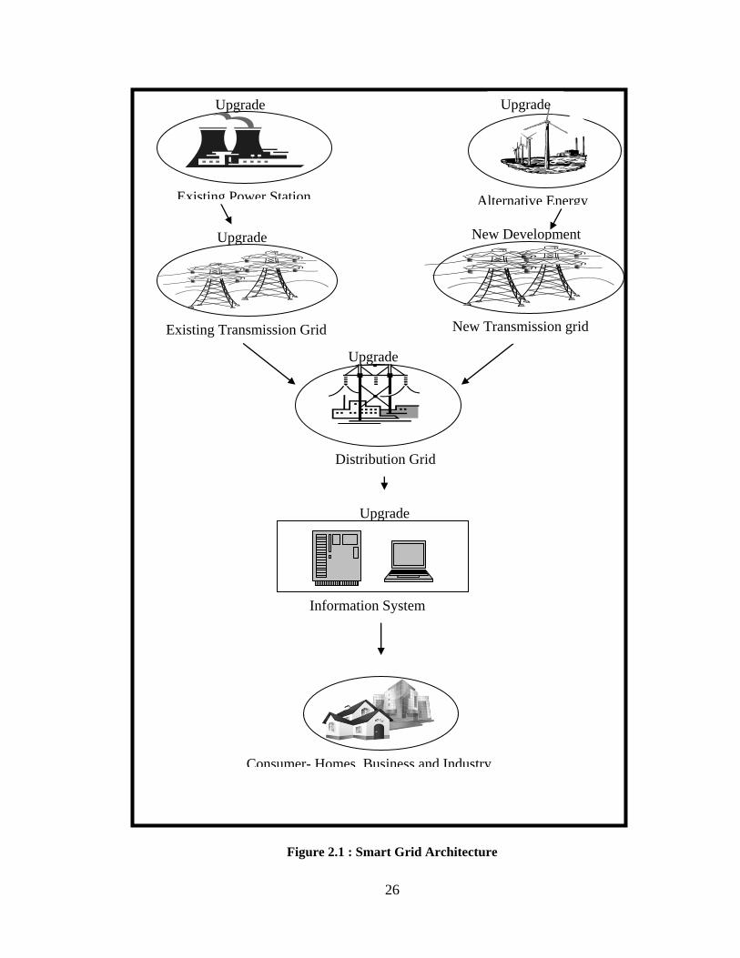
2.2.1. Architecture of the U.S. Smart Grid
Generation, transmission and distribution, have been clearly demarcated since the
genesis of the power system as its main components. A smart grid comprises of two
principal components, the electrical generation and transmission component and the
information technology component. To implement a smart grid in the U S, the following
will have to be considered as shown in figure 2.1:
Upgrading the existing electric grid to make it suitable to transport, monitor and
control generated electricity.
Build new grids from the sources of renewable energy generation to consumers.
26
Figure 2.1 : Smart Grid Architecture
Upgrade
Alternative Energy
Source
Upgrade
Upgrade
Existing Transmission Grid
Distribution Grid
Upgrade
Existing Power Station
Upgrade
Consumer- Homes, Business and Industry
Information System
Upgrade
New Development
New Transmission grid
27
2.2.2. Benefits of Smart of Smart Grids
Several reasons have been given for the need for a new transmission grid.
According to the United States Energy Information Agency (EIA 2008), there is going to
be a 30% increase in U.S. electricity consumption by 2030. This is the new load
equivalent to 2006 electricity usage in California, Texas, Florida, Ohio and Pennsylvania
combined (EPRI 2009). Chamiedes (2009) and the Electricity Advisory Committee EAC
(2008) give the reasons for a need a smart power grid follows:
Economics and Reliability
Benefits to Consumers
Environmental Reasons
Benefits to Generation, Transmission and Utility Companies
Economics and Reliability
Smart grids could reduce the need for direct investments in maintaining and
rebuilding new generation, transmission and distribution systems to match demand from
population growth (GEA 2008). According to EPRI (2003), $1.8 trillion of additional
revenue will be realized from a more efficient and reliable grid. These savings can be
invested into other sectors of the economy.
The power grid involves untold numbers of switches and substations connecting
power plants to households and businesses whose electrical demands rapidly fluctuate in
time. Unfortunately, the grid is highly sensitive to small variations in voltages. When a
local failure triggers a cascade of failures, blackouts can roll across entire states – e.g. the
2003 Northeast United States Blackout which cost more than $6 billion (ELCON 2004).
Such a major blackout is rare, however, short lived interruptions and fluctuations are

28
more the norm. On paper, the power systems is 99.97% reliable, nevertheless, this is the
equivalent of $150 billion of interruptions annually (GEI 2008). With an increasing
digital world, even the change in power quality can cause a loss of information processes
and productivity (GEI 2008). This reliability problem will deteriorate further as the
power system continues to age.
To address such problems, the smart grid will be ―self-healing,‖ meaning that
two way communications will help utilities to remotely detect, isolate, and fix problems
in real-time with little or no human intervention (GEI 2008, Chiamedes 2009).
Benefits to Consumers
Current in the grid flows in a single direction – power is sent from plants to the
consumer. The current grid does not monitor real- time usage by consumers or any
generating contributions from micro renewable sources installed in homes. To ensure that
there is enough power to satisfy all demand needs, power companies always kept excess
capacity generators on hand; these extra generators usually are the oldest and most
inefficient plants. Most of the electricity produced is wasted. A smart grid would interact
with consumers and their smart appliances through an automated metering infrastructure,
adjusting power supply and demand in real-time to maximize efficiency while guarding
against system overloads (Chiamedes 2009, DOE 2009a, Faruqui et al 2009, NETL
2009). This two-way communication system made possible through the automated
metering infrastructure (AMI), smart meters and the home area network (HAN) help
consumers effectively manage their usage habits through automation of systems from the
home. This in turn saves consumers money on energy usage, and enhances the efficiency
level of the power system (EAC 2008).

29
Environmental Reasons
With the current discussion on climate change and demand on fossil fuels, there
has been an intensive push by the government to reduce pollution from economic
activities with minimum effect on these activities economically.
The current grid was designed for generating facilities like coal-fired plants:
always operating at or near capacity. However, this assumption in design was based on a
worldview of plentiful and cheap fossil energy resources, where inefficiencies and
wastage were accepted as a by-product of operation (Chiamedes). Population growth,
dwindling fossil fuel supplies, global climate change concerns, and security reasons
demand renewable energy sources such as wind and solar. Renewable resources tend to
be: spatially distributed and intermittent, so energy storage systems are needed to enable
their continuous contribution to the non-stop electrical demands of consumers (PNNL
2002, Chiamedes 2009, DOE 2009a). Such a flexible grid would use intelligent systems
to handle a wide variety of power sources and storage systems while also maintaining
stability of power generated.
Implementation of smart grid could reduce emissions of gases into the atmosphere
by the implementation of demand response practices. These will eliminate the generation
plants used for peak supplies. These plants are usually the most inefficient and costliest to
operate.
Benefits to Generation, Transmission and Utility Companies
The transmission system, in line with the DOE (2003) Grid Vision 2030, will
enable expanded transmission and distribution of electricity from a multitude of sources,
serving customers in a non-discriminatory manner (DOE 2003. Collier 2008, EAC 2008,

30
Chiamedes 2009).Wind is most prevalent in The Midwest states of Iowa, Montana and
the Dakotas, but the major population centers are concentrated on the East and West
Coasts. There is therefore a need to get the - energy to these population centers with a
minimum of resistive losses. As such, outmoded trunk lines will need to be replaced with
single high-voltage transmission lines that cross the nation incorporating nodes along the
way that allow individual sub-grids or generating stations to plug in (DOE 2003,
Chiamedes 2009).
By reducing peak demand, there will be a corresponding reduction in demand for
additional infrastructure. This extrapolates to a reduction in cost for building generation
plants and corresponding transmission and distribution systems. Smart grid will
drastically increase the efficiency of power delivery. Excel Energy (2008) estimates line
loses to about 30 % of generated energy. These deferred capital investments and savings
form loss prevention, will be a saving available to companies (EAC 2008).
2.2.3. Smart Grid Projections
Smart grid is expected to experience a gradual sustained level of growth over the next
few years. According to NASDAQ (2010), estimates from research done by the Pike
Group expects $53billion to be invested in smart grid technology in the US and $200
billion to be invested globally from 2008 to 2015. GTM Research (2010) expects the
smart grid market to grow from 5.6 billion in 2010 to 9.6 billion in 2015. The report also
anticipates a 48% national deployment of smart meters by 2015.

31
2.3. SMART GRID TECHNOLOGIES
The adaptation of smart grids culminates with the development and
implementation of a wide range of technologies. These technologies will be integrated
into the existing power system. The National Electric Technology Laboratory (NETL)
(2007a) and (Roncero 2008) grouped smart grid technologies into 5 key technology areas
(KTA). These areas are:
Sensing and Measurement
Advanced Components
Advanced Control Methods
Integrated Communications
Improved Interfaces and Decision Support
Sensing and Measurements
These technologies will receive and convert operational information from
components into data. Sensing and measurement technologies will check the operation
quality of the individual components and the grid as a whole. The smart meter and the
home area network (HAN) which are expected to enable demand response (DR) are the
most widely anticipated change at the customer-end of the grid. Several wide-area
monitoring systems like sag meters are being employed at the transmission ends of the
grid at the utility and transmission levels. These advanced sensing measurement tools
will track and transmit data to power system operators (NETL 2007b).
32
Advanced Components
These technologies are components of the grid which will determine the way the
grid works. The technologies will be based on advanced research and development gains
in superconductivity, chemistry materials and microelectronics (NETL 2007c). Advanced
components include power electronic devices like an AC/DC inverters, superconductors
and energy storage devices. Advanced components are at several stages of development
from research to commercially available.
Advanced Control Methods
―Advanced Control Methods (ACM) are the devices and algorithms that will
analyze, diagnose, and predict conditions in the modern grid and determine and take
appropriate corrective actions to eliminate, mitigate, and prevent outages and power
quality disturbances (NETL 2007d).‖ ACM will measure, analyze and diagnose data and
autonomously respond to system faults.
Integrated Communications
These are fully integrated two-way communication technologies that will make
the grid a dynamic interactive system for power and real time data exchange (NETL
2007e, Roncero 2008). A variety of communication technologies are utilized in today‘s
grid but most of these lack full high speed communication integration. The integrated
communication protocol will have to achieve universality, integrity, ease of use, cost
effectiveness, standards, openness, and security to be most effective (NETL 2007e).
Improved Interfaces and Decision Support (IIDS)
IIDS will be the human interface software of the smart grid. IIDS technologies
will convert complicated power system data to easy to use information to aid decision

33
making support. The IIDS will have a two-way communication capability where it might
be able to send and receive data from the customer to aid decision making both at the
utility and the HAN (NETL 2007f).
2.4. INFRASTRUCTURE INSTALLATION AND CONSTRUCTION
MANAGEMENT
Literature on the installation and construction management of power systems and
by extension smart grids is limited. However, construction management and installation
considerations for other infrastructure developments have been considered, in this
instance installing a highway project was considered due to the similarities it has with the
power grid in terms being a means of spanning long stretches of land area.
Installation and Construction Management of Highway Construction
The development of a highway consists of four main distinct phases planning, design,
construction and operation (EPA 1994, FHWA).
Planning /Preconstruction
On a highway project, the decision to build and the hiring of professionals are
done during this stage. The permitting process and land acquisition is initiated at this
stage. Public comments are solicited and then funding is secured.
The design idea is considered for the highway in the preconstruction stage, e.g.,
what highway type, number of interchanges and corridor routes are selected. The projects
schedule and accompanying estimates are monitored. This stage is critical to the success
of the project as it will dictate the use, appearance, construction and operational
34
costs(Gould 1997) The destruction on the ecosystem and potential degradation is
determined at this stage is also determined at this stage (EPA 1994) . According to
Transtech Management (2000), larger projects take longer to plan for and complete
highway projects take about 9-19 years from planning to completion (GAO 2002).
Design and Right of Way Acquisition
During this stage the siting of the right-of-way footprint is determined. The
highway width, slope and types of bridges and crossing structures are determined (EPA
1994). The highway budget and schedule continue to be monitored. All structural parts of
the road are finalized.
Also, during this stage citizens to be affected by construction are relocated and
project cost and estimates are finalized Contract documents are developed and the
bidding and contract award process undertaken to select a contractor depending on the
delivery system used (Gould 1997).
Construction Phase
The actual work of construction is done during this phase; this includes vegetation
removal, moving earth and road building activities. The severity of the impact on the
environment (e.g., erosion and habitat disturbance) is dependent on the construction
methods applied (DOE 1994).
Project Closeout, Operation and Maintenance Phase
The project completion, demobilization and all the post construction maintenance
activities is categorized under this phase. The Maintenance routine including the
following (Krame et al 1985; EPA 1994)

35
Roadway patching and paving
Litter collection
Vegetation control ( e.g., mowing planting seeding etc)
Snow removal, street cleaning and pavement marking
All these construction management and installation aspects of highway construction can
adopt and modified for smart grids.
2.5. SUMMARY
This chapter is the compilation of the current knowledge in smart grids which is
relevant to this research and will be the foundation on which outputs in the proceeding
chapters will be based.

36
CHAPTER THREE
SMART GRID INITIATIVES
3.1. OVERVIEW
The existence and growth of smart grids is greatly influenced by various initiatives
that are being introduced in recent years. Different levels of government and industry
have rolled out various initiatives to support the electric grid as a whole and its various
components and technologies.
The United States federal government has made the goal of upgrading the national
electric grid system a matter of priority. The Energy Independence and Security Act
(EISA) of 2007 define the implementation of the smart grid. There are, however, multiple
challenges and issues that surround the implementation of the smart grid as identified by
the ISO New England (2009).
The Federal Energy Regulatory Commission (FERC) and the States cannot agree on
how to allocate costs for smart grid investments across transmission (federally
regulated) and distribution (state regulated) systems.
The lack of consistent standards and protocols for smart grid technologies limits grid
interoperability (e.g., the sense and respond (S&R) communication capabilities that
are required for the automated real time control of electricity supply and demand).
Lack of coordination among different organization and agencies has produced
varying descriptions and definitions of the smart grid.
This chapter presents the vision of the smart grid by the Federal government. It
then, summarizes initiatives by different levels of government, various transmission and

37
utility companies, renewable energy generation industry, and the information technology
sector related to smart grids.
3.2. SMART GRID VISION 2030
In 2003, the United States Department of Energy‘s (DOE) Office of Electric
Transmission and Distribution, commissioned a committee of 65 senior executives
representing the federal government, the electrical and utility industry, equipment
manufacturers, information technology providers, universities, interest groups, and the
national laboratories to develop a 25 year vision for the national electric grid. This vision
document was named ―Grid Vision 2030‖ (DOE 2003).
The vision of Grid 2030 is a ―fully automated power delivery network that
monitors and controls every customer and node, ensuring a two way flow of electricity
and information between the power plant and the appliance, and all points in between. Its
distributed intelligence, coupled with broadband communications and automated control
systems, enables real time market transactions and seamless interfaces among people,
buildings, industrial plants, generation facilities and the electric network (DOE 2003).‖
Simply stated, the goal of ―Grid Vision 2030‖ is to achieve a fully functional and
operational smart grid system by the year 2030. In order to achieve this goal, following
three major element of the grid were considered, as shown in Figure 1 (DOE 2003):
a national electricity ―backbone‖
regional interconnections, which includes Mexico and Canada
local distribution, mini- and micro- grids providing services to customers and
obtaining services from generation sources anywhere on the continent

38
3.2.1. National Electricity Backbone
A national electricity backbone is the foundation on which the smart grid will be
developed. It will consist of high-capacity transmission corridors, connecting the various
states on the US mainland and also including Canada and Mexico. This national
electricity backbone will enable expanded distribution of electricity from (DOE 2003):
An efficient generation and transmission from a multitude of generation sources,
and;
A more efficient system that can adapt to seasonal and regional weather variations
on a national scale.
The backbone system will include a variety of technologies including low-
impedance superconducting cables and transformers operating on alternate current (AC);
high voltage direct current devices forming connections between regions; and other types
of advanced electricity conductors. Information, communications, and control
technologies for supporting real-time operations and demand response will be included
(DOE 2003).
3.2.2. Regional Interconnections
Power from the national electricity backbone system will be distributed over
regional networks. These long-distance high transmission networks within these regional
centers will be accomplished using upgraded, controllable AC systems and, in some
cases, expanded DC links (DOE 2003).

39
Regional transmission systems and utilities will benefit from the real time
generation and consumption information transferred over the network between generation
sources and the end user. The use of advanced storage devices will address demand and
supply imbalances resulting from weather limitations, the intermittent supply patterns
from renewable sources, and the peak demand power usage patterns of consumers (DOE
2003).
3.2.3. Local Distribution Grids
Local distribution systems will be connected to the regional networks and finally,
to the national electric backbone. Real-time monitoring and information exchange will
enable the electrical markets to process transactions instantaneously and on a nationwide
basis. Customers will have the ability to tailor their individual household electricity usage
to the variable rates determined by the demand response and real time monitoring of the
electric system. Sensors and control systems will link appliances and equipments from
inside the buildings to the utilities through the distribution system. Figure 2 illustrates a
sample of the potential products and services that will be achieved under ―Grid Vision
2030‖ and their planned timeline (DOE 2003).
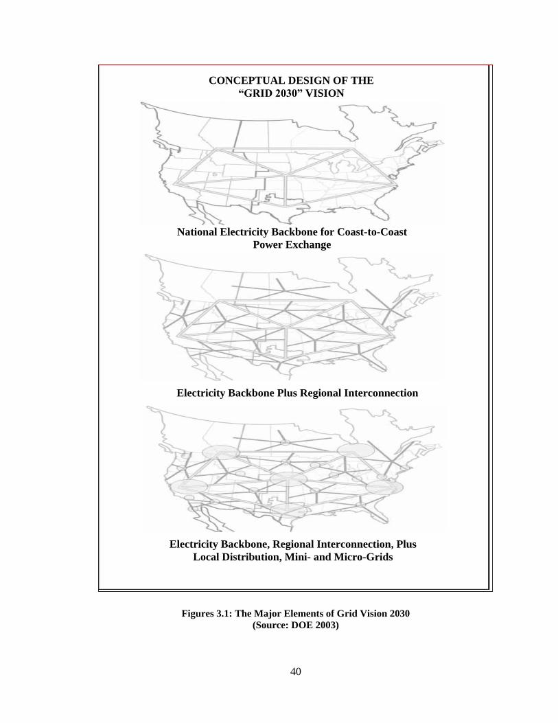
40
Figures 3.1: The Major Elements of Grid Vision 2030
(Source: DOE 2003)
CONCEPTUAL DESIGN OF THE
“GRID 2030” VISION
National Electricity Backbone for Coast-to-Coast
Power Exchange
Electricity Backbone, Regional Interconnection, Plus
Local Distribution, Mini- and Micro-Grids
Electricity Backbone Plus Regional Interconnection

41
Figure 3.2: Grid Vision 2030 Potential Products and Services and their Timeline
(Source: DOE 2003)

42
3.3. INITIATIVES BY THE FEDERAL GOVERNMENT
Several initiatives to support the upgrading and adoption of smart grid
technologies are being offered by federal, state and local governments and private
industry stakeholders in the electricity generation, transmission and distribution sector.
The initiatives undertaken by the federal government can be divided into two broad
categories:
Regulatory Initiatives
Investment Initiatives
3.3.1. Regulatory Initiatives
To ensure a smooth transition from the existing grid to smart grid, removing
bottlenecks and conflicts in the adoption of smart grid technologies has become a priority
of the federal government. In order to help achieve this aim, the federal government has
been pursuing regulatory policies and initiatives to encourage the investment, innovation,
installation, and operation of smart grid technologies. Major regulatory policies and
initiatives are:
Energy Policy Act (EPACT) 2005
Title II of EPACT 2005 is focused entirely on renewable energy generation.
EPACT set the federal target percentages for renewable energy to 3% for 2007-2009, 5%
for 2010-2012, and 7.5% for 2013 and beyond (Bluvus 2007).
The Energy Independence and Security Act of 2007 (EISA) - Title XIII
The Energy Independence and Security Act (EISA) of 2007 amended the Energy
Policy Act 2005 by strengthening the regulatory requirements and articulated a national

43
policy to modernize the power system with smart grid technology, authorized research
and development programs, provided funding for demonstration projects and authorized
matching funds for investments in smart grid technology (ISO New England 2009).
Under the EISA law, the National Institute of Standards (NIST), a unit of the
Department of Commerce, was assigned to lead the development of interoperability
standards for smart grid equipments and systems. Interoperability standards once
developed and agreed upon, will make it easier for the manufacturers of smart
components and the utility companies to develop compatible components and systems for
the smooth operation of the grid. The DOE, Federal Energy Regulatory Commission
(FERC) and NIST have begun interagency efforts to speed the development of these
standards. NIST has created a new office of ―The National Coordinator on Smart Grid
Interoperability;‖ to push the effort of adopting interoperability standards forward
(Siciliano 2009).
The NIST plan calls for establishing technical domain expert working groups
responsible for developing interoperability issues and lead the technical direction.. Areas
that lack or require additional standards development include (NIST 2008):
Building-to-grid (B2G) standards
Industrial-to-grid (I2G) standards
Home-to-grid (H2G) standards
Domain interfaces
Cross-cutting issues.
A sample of the initiatives by DOE and NIST under EISA are summarized in Table 3.1.

44
Table 3.1: EISA Smart Grid Initiatives and Deadlines (Modified From: ISO New England 2009)
Initiative Target Date Status Comments
NIST develops an interoperability framework that includes protocols and model
standards for information management to achieve interoperability of Smart Grid
devices and systems.
February
2008
Completed
DOE establishes the Smart Grid Advisory Committee and Smart Grid Task Force. March 2008 Completed
Smart Grid Task Force reports to Congress on the status of Smart Grid deployments
nationwide and regulatory or government barriers to continued deployment.
December
2008
Completed
NIST publishes progress report on recommended or consensus standards and
protocols in the interoperability framework.
December
2008
Pending
DOE publishes procedures for reimbursement of qualifying Smart Grid investments. December
2008
Pending
DOE studies and reports on the effect of private distribution wire laws on the
development of combined heat and power (CHP) facilities.
December
2008
Pending
DOE reports to Congress identifying existing and potential impacts of the
deployment of Smart Grid systems on improving the security of
the nation‘s electricity infrastructure and operating capability.
June 2009 Pending
DOE establishes a regional Smart Grid demonstration initiative that specifically
focuses on demonstrating advanced technologies for use in power grid sensing,
communications, analysis, and power-flow control.
February
2010
Pending Demonstration
programs with regional
utilities under Smart
grid Grants
DOE develops advanced R&D of power grid digital information
Technology.
None Unknown

45
3.3.2. Investment Initiatives
Obtaining funding has been a major impediment to transmission expansion
(Roseman & De Martini 2003). Utility companies have traditionally raised money from
equity investors, internal cash flow, and bond holders. After the Three Mile Island
nuclear accident in 1979 and the California energy crisis in 2002 and 2003, and
subsequent bankruptcy of Enron and Pacific Gas & Electric Company, private investment
into utility related bonds reduced drastically (Abel 2008, Business Week 2003). In recent
years, the power sector has begun to experience an upward trend in bond ratings (Abel
2008). The federal government and some state governments, in an attempt to increase
confidence in the energy sector, and encourage investment, have undertaken various
initiatives to attract investment towards upgrading the power grid.
Energy Policy Act (EPACT) 2005
The energy production tax credits for companies, who research and manufacture
components, and invest in renewable generation plants, were extended for two more
years. The Act also created clean renewable energy bonds for qualifying entities that
invest in renewable energy generation (Bluvus 2007).
The American Reinvestment and Recovery Act (ARRA) 2009
The American Reinvestment and Recovery Act 2009(ARRA) included 3.4 billion
dollars, through DOE, for upgrading the power grid with matching funds from utility
companies and industry. This amount represented the largest single energy investment in
US history, funding a broad range of technologies to spurn an increase in efficiency and
foster growth of renewable energy sources and distribution (DOE 2009, DOE 2009d, and

46
Renewable Energy World 2009). The DOE grants are summarized in Table 3.2 and
sample projects under each category are provided in table 3.3.
Soon after, DOE announced its second round of funding opportunities totaling
$100 million for transformational energy research projects through its Advanced
Research Projects Agency-Energy (ARPA-E). In this round of funding, projects focused
on Smart Grid technologies research in biofuels, carbon capture and electric vehicle
batteries (Smartgridnews 2010).
Table 3.2. ARRA Project Breakdown Summary (Adopted From: DOE 2009, DOE 2009d,
and Smartgridnews 2010)
ARRA Project Summary
- Smart Grid Investment Grant Program; 3 years $3,400 million
Smaller projects, $300K-$20M; 40% of funding
Larger projects, $20M-$200M; 60% of funding
The funds were awarded in 6 broad categories namely:
Advanced Metering Infrastructure AMI
Customer Systems
Electric Distribution Systems
Electric Transmission Systems
Equipment Manufacturing
Integrated and/or Crosscutting Systems
- Smart Grid Demonstrations Program; 3-5 year $700million
Regional Demonstrations, up to $100M per project
Grid-scale Energy Storage Demonstrations
- Grid-scale Energy Storage Demonstrations
- Resource Assessment and Interconnection-Level Transmission Analysis and planning $80
million
- State Electricity Regulators Assistance $50 million
- Enhancing State Government Energy Assurance Capabilities and Planning for Smart Grid
Resiliency $55 million
- Workforce Development $100 million
- Interoperability Framework Development by NIST $10 million
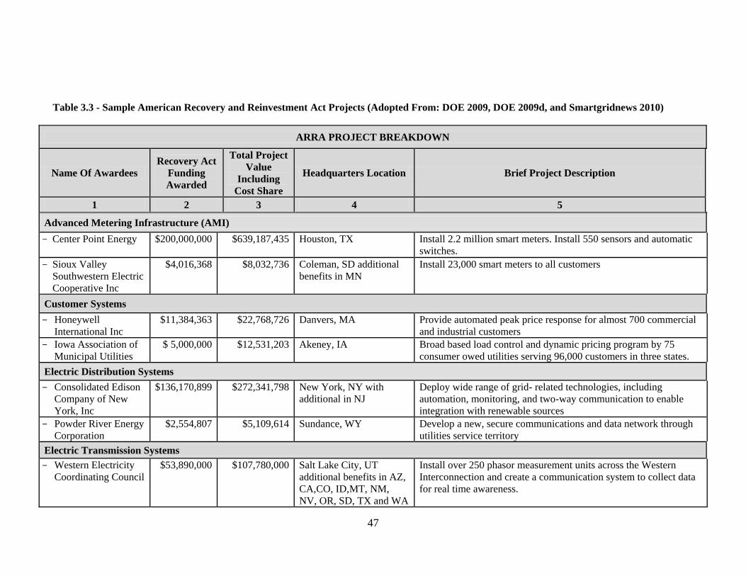
47
Table 3.3 - Sample American Recovery and Reinvestment Act Projects (Adopted From: DOE 2009, DOE 2009d, and Smartgridnews 2010)
ARRA PROJECT BREAKDOWN
Name Of Awardees
Recovery Act
Funding
Awarded
Total Project
Value
Including
Cost Share
Headquarters Location Brief Project Description
1 2 3 4 5
Advanced Metering Infrastructure (AMI)
Center Point Energy $200,000,000 $639,187,435 Houston, TX Install 2.2 million smart meters. Install 550 sensors and automatic
switches.
Sioux Valley
Southwestern Electric
Cooperative Inc
$4,016,368 $8,032,736 Coleman, SD additional
benefits in MN
Install 23,000 smart meters to all customers
Customer Systems
Honeywell
International Inc
$11,384,363 $22,768,726 Danvers, MA Provide automated peak price response for almost 700 commercial
and industrial customers
Iowa Association of
Municipal Utilities
$ 5,000,000 $12,531,203 Akeney, IA Broad based load control and dynamic pricing program by 75
consumer owed utilities serving 96,000 customers in three states.
Electric Distribution Systems
Consolidated Edison
Company of New
York, Inc
$136,170,899 $272,341,798 New York, NY with
additional in NJ
Deploy wide range of grid- related technologies, including
automation, monitoring, and two-way communication to enable
integration with renewable sources
Powder River Energy
Corporation
$2,554,807 $5,109,614 Sundance, WY Develop a new, secure communications and data network through
utilities service territory
Electric Transmission Systems
Western Electricity
Coordinating Council
$53,890,000 $107,780,000 Salt Lake City, UT
additional benefits in AZ,
CA,CO, ID,MT, NM,
NV, OR, SD, TX and WA
Install over 250 phasor measurement units across the Western
Interconnection and create a communication system to collect data
for real time awareness.

48
Table 3.3. Sample American Recovery and Reinvestment Act Projects
(Adopted From: DOE 2009, DOE 2009d, and Smartgridnews 2010) (Continued)
2 1 4 5
Midwest Independent
Transmission System
Operator
$17,271,738 $34,543,476 Carmel IN, with
additional benefits in IA,
IL, MI, MO, MT, ND,
OH, PA, SD and WI
Install, test , integrate and monitor 150 phasor measurement
units in strategic locations across the Midwest on independent
transmission operators.
Equipment Manufacturing
Whirlpool
Corporation
$19,330,000 $38,681,000 Benton Harbor, MI Support the manufacture of smart appliances to accelerate the
commercialization of residential appliances capable of
communicating over a home network with other smart
technologies.
Georgia System
Operations
Corporation Inc
$6,456,501 $12,913,003 Tucker, GA Upgrade computer systems to instantaneously and
automatically communicate information about disruptions or
changes in flow on the grid. Use digital controls to manage
and modify electricity demand
Integrated and Crosscutting Systems
Duke Energy
Business LLC
$200,000,000 $851,700,000 Charlotte, NC with
additional benefits in IN
and OH
Comprehensive grid modernization for Duke‘s Midwest
electric system encompassing OH, IN and KY. Includes
installing open, interoperable, two-way communications
networks, deploying smart meters, automating advanced
distribution applications and support for plug in electric
vehicles.
Detroit Edison
Company
$83,828,878 $167,657,756 Detroit, MI Smart Currents program includes deploy a large scale network
of 660000 smart meters, implement the SmartHome program
which will provide dynamic pricing and smart appliances to
customers and SmartCircuit to improve grid distribution
operations through circuit upgrades.

49
Emergency Economic Stabilization Act of 2008.
In the Emergency Economic Stabilization Act of 2008, the depreciation period for
smart grid meters and other grid equipments as specified in the EISA Act of 2007, was
reduced from 20 years to 10 years. The value of this tax change to the power industry is
reportedly $915 million over 10 years (EAC 2008, Kaplan 2009).
Tax Incentives
There have been several tax credits and incentives passed by the U.S. Congress to
encourage the investment and adaptation of renewable energy generation. Table 3.4
summarizes some of the tax credits/incentives enacted for renewable energy producers
and smart grid technology (DSIRE 2010).
Table 3.4 – Sample Federal Tax Credits/Incentives (Source: DSIRE 2010)
Credit Incentive
Type Applicable Sector Remarks
Renewable Electricity
Production Tax Credit
Corporate
Tax Credit
Renewable
Generation
http://www.irs.gov/
pub/irs-
pdf/f8835.pdf
Modified Accelerated Cost-
Recovery System (MACRS) +
Bonus Depreciation (2008-2009)
Corporate
Depreciatio
n
Renewable
Generation
26 USC § 168
US DOE Agriculture Rural
Energy America Program
(REAP) Loan Guarantees
Rural
Renewable
Generation
Renewable
Generation
http://www.rurdev.
usda.gov/rbs/busp/
bprogs.htm
U.S. Department of Energy -
Loan Guarantee Program
Federal
Grant
Program
Energy efficiency,
renewable energy
and advanced
transmission and
distribution projects
http://www.lgprogr
am.energy.gov
3.4. INITIATIVES BY STATE GOVERNMENTS
Several state governments have enacted laws to encourage the adoption of smart
grid technologies and renewable energy generation sources. Most of these states have

50
also adopted Renewable Energy Portfolio Standards (REPS), stipulating all utility
companies to acquire a set percentage of their distributed electricity from renewable
sources by a certain future time (AWEA 2010). According to a smartgridnews.com’s
survey of the ―smartest‖ states (Smartgridnews 2010), California came out as the state
with the most well defined combination of policy initiatives and potential. In addition,
California utilities such as, Southern California Edison (SCE), is undertaking a smart grid
demonstration project and installing smart meters to all its customers through the
American Reinvestment and Recovery Act (Berst 2009). Texas, Ohio and states in New
England also came up for special mention. Almost all 50 states have some form of
legislative initiatives related to renewable energy and energy efficiency that are either
being worked on or have already passed into law. Below are some of the major
initiatives in key states.
3.4.1. California
SB 837 (Florez) Smart Grid Technologies (Introduced in January 2010)
This bill states the intent to enact legislation to ensure that the electrical
companies, authorized to deploy smart grid technology including smart meters, are
meeting their intended goals and have not shifted unnecessary deployment costs onto
consumers. (Florez 2010)
AB 2514 (Skinner) Energy Storage Portfolio Standard (Introduced in February
2010)
This bill would require each electrical utility, as of January 1, 2014, to procure
new energy storage systems that can provide specified percentages of the utility‘s average

51
peak electrical demand using stored energy that was generated during off-peak periods of
electrical demand. The bill would also require each electrical utility to develop plans to
meet the energy storage portfolio procurement requirements and to report certain
information to the State Energy Commission (Skinner 2010).
SB 17 (Padilla) – Electricity: smart grid systems. (2009)
This bill requires, by July 1, 2010, the California Utilities Commission, in
consultation with the State Energy Commission and other key stakeholders, to determine
the requirements for a smart grid deployment plan. It requires each electrical utility, by
July 1, 2011, to develop and submit a smart grid deployment plan to the commission for
approval. The bill also authorizes for the deployment of smart grid products,
technologies, and services by entities other than the electrical utilities (Padilla 2010).
The California Solar Initiative Research, Development, Demonstration and
Deployment (RD&D) Plan (2010)
This plan authorized the California Public Utilities Commission to set aside $50
million to help build a sustainable and self-supporting industry for customer-sited solar
energy installations.. In order to achieve the above-stated goal, following areas were
emphasized (CPUC 2010):
Reducing technology costs and increasing system performance.
Focusing on issues that directly benefit California.
Filling knowledge gaps to enable wide-scale deployment of distributed solar.
Supporting the integration of distributed power into the grid
As part of this plan, the California Public Utilities Commission (CPUC) has
begun the rulemaking process to consider policies for investor-owned electrical utilities
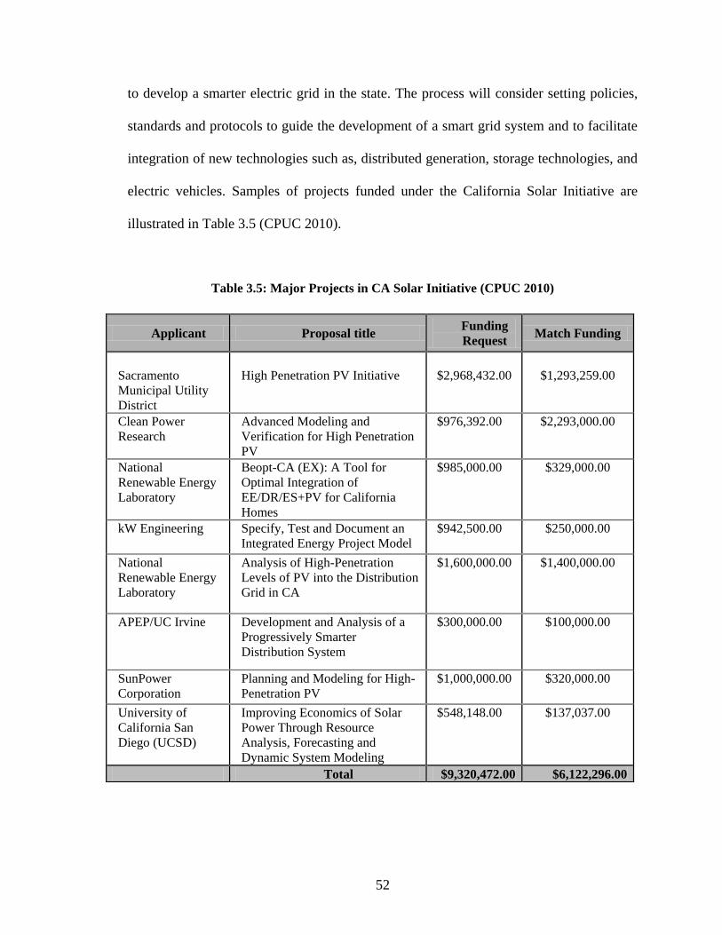
52
to develop a smarter electric grid in the state. The process will consider setting policies,
standards and protocols to guide the development of a smart grid system and to facilitate
integration of new technologies such as, distributed generation, storage technologies, and
electric vehicles. Samples of projects funded under the California Solar Initiative are
illustrated in Table 3.5 (CPUC 2010).
Table 3.5: Major Projects in CA Solar Initiative (CPUC 2010)
Applicant Proposal title Funding
Request Match Funding
Sacramento
Municipal Utility
District
High Penetration PV Initiative
$2,968,432.00
$1,293,259.00
Clean Power
Research
Advanced Modeling and
Verification for High Penetration
PV
$976,392.00 $2,293,000.00
National
Renewable Energy
Laboratory
Beopt-CA (EX): A Tool for
Optimal Integration of
EE/DR/ES+PV for California
Homes
$985,000.00 $329,000.00
kW Engineering Specify, Test and Document an
Integrated Energy Project Model
$942,500.00 $250,000.00
National
Renewable Energy
Laboratory
Analysis of High-Penetration
Levels of PV into the Distribution
Grid in CA
$1,600,000.00 $1,400,000.00
APEP/UC Irvine Development and Analysis of a
Progressively Smarter
Distribution System
$300,000.00 $100,000.00
SunPower
Corporation
Planning and Modeling for High-
Penetration PV
$1,000,000.00 $320,000.00
University of
California San
Diego (UCSD)
Improving Economics of Solar
Power Through Resource
Analysis, Forecasting and
Dynamic System Modeling
$548,148.00 $137,037.00
Total $9,320,472.00 $6,122,296.00

53
3.4.2. New England States
Several States in New England have adopted policies and enactments to encourage
smart grid adoption. Table 3.6 summarizes some of the major initiatives (ISO New
England 2009).
Table 3.6 - Smart Initiatives in New England (Modified from: ISO New England 2009)
State Description Scope References
MA The Massachusetts 2008 Act
Relative to Green
Communities, signed into law
July 2008,
Mandates for Utilities to file
plans for Smart Grid pilot
projects by April 2009
http://www.mass.go
v/legis/laws/seslaw0
8/sl080169.htm
RI Rhode Island Senate Bill S
2851
Implement smart meters and
to demonstrate smart grid
implementation
http://www.rilin.stat
e.ri.us/BillText08/Se
nateText08/S2851
Aaa.pdf
NH Southern New Hampshire
University is testing a real
time controller for PHEVs
that can respond to price
signals from the five-minute
electricity grid spot market.
The vehicles will make
money selling power into the
grid during high-load
conditions by responding to
five minute spot market
price signals, for example,
$0.25/kilowatt-hour (kWh)
May 9, 2008
http://www.nhbr.co
m/apps/pbcs.dll/artic
le?AID=/20080509
/INDUSTRY17/437
649673/-
1/Industry17
CT Connecticut Light and Power
currently is engaged in an
advanced metering
infrastructure project
Smart meter infrastructure http://www.amraintl.
org/symposium/200
7Papers/Papers/4ES
cott.pdf
CT Connecticut announces the
Solar Lease program.
August 20, 2008
Help low- and moderate-
income residents acquire
photovoltaic solar power
systems.
www.sustainablebus
iness.com/index.cfm
/go/news.display/id/
16603
3.5. INITIATIVES BY LOCAL GOVERNMENTS
Several cities and counties have also taken initiatives to promote smart grids. For
example, in 2008, Excel Energy, a utility company in Colorado, in conjunction with the
54
city of Boulder Colorado, initiated a 5 year citywide smart grid implementation pilot
program. This pilot project will include smart grid components in the distribution and
consumer networks (Excel Energy 2008). Similarly, the city of Austin, TX, is
collaborating with the Austin Energy to set up a smart grid project (Burkhalter 2008).
3.6. INITIATIVES BY THE TRANSMISSION COMPANIES
Electric Power (AEP) Transmission Company
American Electric and Power (AEP), a shareholder-owned utility company, has
outlined plans to build a new 765-kilovolt (kV) transmission line stretching from West
Virginia to New Jersey. The proposed transmission superhighway would span
approximately 550 miles. It is designed to reduce congestion costs in the regional
transmission by substantially improving the ability to transfer electricity from West to
East. The transfer capability will improve by approximately 5,000MW when completed
and the projected investment will be about $12 billion by 2013 (EEI 2005, AEP 2006).
ITC Holdings
ITC Holdings, an electricity transmission company, is developing a 12,000-
megawatt transmission network to transport renewable energy from wind farms in the
Midwest to large population centers like Chicago and Minneapolis. This initiative, known
as the ―Green Power Express‖ will add about 3,000 miles of high-voltage transmission
lines across parts of North Dakota, South Dakota, Minnesota, Iowa, Wisconsin, Illinois
and Indiana. The project is estimated to cost between $10 billion to $12 billion.
(Greenbang 2009). Other subsidiaries of ITC Holdings, namely ITC transmission, ITC

55
Midwest and ITC Great Plains are pursuing similar projects in their respective regions of
operations (ITC 2009).
3.7. INITIATIVES BY EQUIPMENT MANUFACTURERS
Many equipment manufacturers and related industry associations have taken steps
to promote the smart grid. Following are some key initiatives:
– The National Electrical Manufacturers Association (NEMA) announced the
completion of SG-AMI 1-2009-Requirements for Smart Meter Upgradeability, the
first Smart Grid standard. This standard provides guidance to utilities and state
commissions on the procurement of automated metering infrastructure (AMI) systems
(NEMA 2009).
– Whirlpool Corp., in April 2009, announced that their appliances will be smart grid
compatible by 2015. They also set a goal of producing 1 million smart dryers by
2011. Similar steps are being taken by other manufacturers including GE (Greenbeat
2009, Gunther 2009).
– Honeywell Company was one of four non-utility companies to receive funding
through the America Recovery and Reinvestment Act. Honeywell will use the grant
to support a critical peak pricing response program that will help commercial and
industrial facilities in the Southern California Edison (SCE) service territory to
automatically implement energy management strategies (Honeywell 2010).

56
3.8. INITIATIVES BY UTILITY COMPANIES
Several utility companies are taking advantage of the matching funds from the
America Recovery and Reinvestment Act (ARRA) grants awarded through DOE. For
example, Columbus Southern Power Company, doing business under the name of AEP
Ohio, has secured a matching federal grant of $75 million to establish the AEP
gridSMART demonstration Project. The aim of the project is to demonstrate a secure
interoperable and integrated smart grid infrastructure for 110,000 consumers, which will
maximize distribution system efficiency and reliability, and enable consumers to reduce
their energy use. It will include 13 different technologies from the substation to the
customer, including distribution automation and control, battery storage, smart
appliances, home area networks, plug-in hybrid electric vehicles, and renewable
generation sources. These technologies are estimated to improve the reliability and
efficiency of the distribution system by 30-40% (DOE 2009).
Several other utility companies have smart grid initiatives on different scales over
the country. Austin Energy in Texas, Southern California Edison in California, and Oncor
and Centerpoint in Texas, has large scale smart grid demonstrations (DOE 2009). In
addition, many utility companies have undertaken non-ARRA initiatives, e.g., those
described under the sections on initiatives by state and local governments.
3.9. INITIATIVES BY RENEWABLE ENERGY INDUSTY
Most initiatives by the renewable energy industry will directly or indirectly
impact the smart grid movement. The growth of new wind and solar energy installations
will particularly influence the growth of new smart transmission grid. According to the
57
American Wind Energy Association, the current capacity of wind generated electricity is
around 35000 MW but major projects are underway that will add substantially to this
figure. For example, British Petroleum is developing about 100 wind farm projects at
different phases of construction and operation that will generate 20,000 MW of electricity
after completion in five states. There are several major projects similar to these under
construction around the country. (AWEA 2010, BP 2009).
3.10. INITIATIVES BY THE INFORMATION TECHNOLOGY INDUSTRY
In recent years, many information technology companies of all sizes have forayed
into smart grid technologies. For example, Intel Corporation, in January 2010, came out
with a Home Energy Management concept as a user interface for homes. This device will
allow one to integrate thermostat functions, energy management tools, home security
monitoring, and other functions such as home network management, task reminders, and
video memos (Zheng 2010). Apple Inc., another major IT company, has recently jumped
into the home energy management arena. The company has applied for patents for a
home energy management system that would allow consumers to reduce electricity bills
by controlling and maximizing how power is allocated to home electronics .The two
Apple patent applications, Intelligent Power Monitoring and Intelligent Power-enabled
Communications, were filed in May 2009 (Smartgridnews 2010). Google has also
introduced its free home energy management software called, Googlemeter and,
Microsoft has introduced its own energy management software called Hohm, which is the
software used by Ford on its hybrid vehicles (Dignan 2010).

58
3.11. SUMMARY
This chapter summarized the national vision for the smart grid and the various
initiatives undertaken by government at all levels and by industry. These initiatives
illustrate the roadmap to the future for the electric grid and demonstrate that smart grids
are going to be a recurring source of opportunities as the grid infrastructure age and
demand for energy continue to increase over the coming years. These initiatives also
highlight the multi-facetted nature of the smart grid movement, along with various
financial incentives and the sectors in which these incentives are promoting business
opportunities.

59
CHAPTER 4
SMART GRID TECHNOLOGIES
4.1. OVERVIEW
This section will explore both the upcoming and the existing major smart grid
technologies. These technologies have been grouped into five broad categories by the
National Energy Technology Laboratory (NETL). An overview of each technology and
its location on the grid will be considered, followed by its development status and
existing installations, if any, that are available.
4.2. INTRODUCTION
In order to understand the various smart grid technologies discussed in this
chapter, the section presents a brief introduction of the power system. The electric power
system consists of three distinct component parts:
Generation
Transmission
Distribution
In between these main components are the step-up and step-down substations, which ease
the transportation of electrical power over long distances (Figure 4.1).
Power Generation
The power generating plant is the foundation of the electric power system. A
power system will consist of several generation stations, distributed over a large area,
operating simultaneously to keep a power balance in the grid (Schavemaker and Van Der
Sluis 2008). When the national grid was started about a century ago, power plants were

60
built near the natural resources used in electricity generation. These were mostly in the
cold industrial centers, near coalmines. By 2008, coal accounted for almost 40% of the
total electricity produced in the US, with nuclear at 19%, natural gas at 21%,
hydroelectric at 6% and non-hydro renewable energy accounting for 3% (EIA 2010).
Alternate sources of energy are prevalent in locations where the national electric
grid does not efficiently reach, and the intermittent generation patterns of wind and solar
mean that the existing grid is not well-suited to alternative energy delivery. As such, with
the advent of alternative energies like solar and wind power, a grid needs to be built that
is suited to these forms of energy; to transport the alternative energy produced to large
population centers.
Figure 4.1: Components of the Electrical Grid (Source: PSC of Wisconsin 2009)
Power Plant Step-Up
Transformer
Customer Service
Drop
(120/240 volts
Primary Distribution
(4kV-46kV
Step-Down
Transformer
Note: kV = 1,000 Volts
Transmission
969-765 kV)

61
Renewable Power Generation
The term ―renewable energy‖ refers to energy derived from a broad range of
resources, all of which are based on naturally renewing energy sources such as sunlight,
wind, flowing water, the earth‘s internal heat, and biomass (Bull 2000). These resources
can be used to produce electricity for all economic sectors. Hydroelectric dams account
for about 6% of total US electricity, and comprise the largest renewable energy source in
the world. Currently, however, renewable sources of energy refer mainly to non-hydro
sources of renewable energy, e.g. solar, wind and geothermal.
Renewable energy sources account for about 3% of the total electricity in the US. The
adoption of renewable energy is still in its formative stages. Government initiatives,
together with more advanced and efficient technologies, are encouraging a rapid
adaptation to renewable energy.
Transmission Substation
Transmission substations connect two or more transmission lines. These
substations contain high-voltage switches that allow lines to be connected or isolated for
maintenance, and shut down without interrupting power supply. A transmission station
may have transformers to convert between two transmission voltages, or equipment such
as phase angle regulators to control the power flow between two adjacent power systems.
Transmission substations can range from simple to complex. The largest transmission
substations can cover a large area with multiple voltage levels, as well as a large amount
of protection and control equipment (capacitors, relays, switches, breakers, and voltage
and current transformers) (USDA 2002).

62
Transmission substations also serve as a protector of the power system. In
substations, protector equipment, like voltage transformers, current transformers and
protective relays are installed, together with circuit breakers and disconnectors, to
perform switching operations. The system is also grounded at the substations
(Schavemaker and Van Der Sluis 2008).
Transmission
High voltage transmission lines are a more efficient means of transporting power
over long distances than low voltage distribution lines. All transmission voltages above
69kV is considered transmission; it is referred to as distribution when it is lower than
69kV.
Transmission lines use shield wires to protect the lines from lightning conditions.
The shield wires are sometimes called static wires or earth wires. The shield wires are
bare and connect the transmission pole to the earth. The shield wires are usually the
highest wires on the transmission pole (Blume 2007).
Distribution
Distribution systems operate at 12.5v-24.5v, and deliver power from transmission
systems to consumers (Blume 2007, Brown 2009). The distribution networks begin at
the distribution transformers. Utilities control most of the distribution of electricity. Like
the transmission systems, distribution systems have congestion problems.
Consumers
Electric consumption encompasses the energy utilized in transporting and
delivering energy, including losses and waste from heating. The consumption can be

63
divided into residential, commercial-industrial and very large energy consumers (Blume
2007).
The adaptation of smart grids will culminate with the development and implementation of
a wide range of technologies. These technologies will be integrated into the existing
power system. The National Electric Technology Laboratory (NETL) 2007a and Roncero
2008 grouped smart grid technologies into 5 key technology areas (KTA). These areas
are:
Advanced Components
Sensing and Measurement
Advanced Control Methods
Integrated Communications
Improved Interfaces and Decision Support
4.3. ADVANCED COMPONENTS
These technologies are components of the grid, which will determine the way in
which the grid will work. The technologies will be based on advanced research and
development gains in superconductivity, chemistry materials and microelectronics
(NETL 2007c). Advanced components will include power electronic devices like AC/DC
inverters, superconductors and energy storage devices. Advanced component
development is at several stages of development, from research to commercially
available. This section reviews the following advanced components:
Energy Storage Devices
Advanced Superconducting Transmission Cables

64
Grid-Tied Invertors
Smart Meters
Demand Response Load Control Receivers
Plug-in Hybrid Electric Vehicles and Electric Vehicles
Electric Charging Stations
Each of the above technologies will be discussed, introducing the technology with an
overview, its location on the grid, its deployment and existing installations.
4.3.1. Energy Storage Devices (ESD)
Large -scale stationary applications of electric energy storage (ESD) can be
divided into three major functional categories (EAC 2008 Gomez et al 2010) :
Power quality applications
Bridging power
Energy Management
High-power ESD applications are usually very short-term applications, lasting a
second or less, and are related to maintaining the quality, reliability and security of power
systems. Capacitors, flywheels, superconducting magnetic energy storage (SMES), and
other similar storage devices are usually utilized for high power storage systems (Gomez
et al, 2010).
In bridging power applications, energy storage systems are deployed for
anywhere from a few seconds to minutes, to assure continuity of service when switching
from one source of energy generation to another (ESA 2009).
For energy management needs, ESDs are deployed from several minutes to hours,

65
to support distributed energy generation or load variations. It can also be applied for the
uninterruptible power supply (UPS) or energy management needs of consumers and
power suppliers.
Depending on the applications used in power systems, the storage capacity can
vary from less than 1 kW to 1 GW. Pumped hydro, Compressed Air Energy Storage
(CAES) and SMES are utilized for large capacities—from tens of MW up to hundreds of
MW—as opposed to capacitors, different types of batteries, and fly wheels, which
usually range from 10 MW down to several kW (Gomez et al 2010). Several storage
technologies are in different phases of development, and those on the market are
constantly undergoing improvements in capacity and longetivity.
Sodium Sulfur (NaS) battery
This technology is an advanced electrochemical storage system that was
developed in Japan, and which has been in demonstration and use in Japan over the past
decade (EPRI 2006). The NaS battery operates at about 300°C, employing an
electrochemical reaction between sodium and sulfur. Molten sulfur at the positive
electrode and molten sodium at the negative electrode are separated by a solid beta
alumina ceramic electrolyte. The basic NaS battery has a capacity of about 50 kW and is
about 89% efficient (ESA 2009, EPRI 2007b3). A 1MW capacity battery will weigh
approximately 88 tons and be equivalent to the size of two semi-trailers. The batteries
have a lifespan of at least 15 years, assuming 2,500 charge/discharge cycles (OE 2009).
The total installation is expensive, in relation to similar storage technologies, due
to the cost of a backup generator, which is needed to keep the battery hot at all times, in

66
the event of a major outage on the grid. The need to maintain high NaS battery
temperatures also has an impact on its efficiency, due to total parasitic losses. This is not
the case, however, if the battery is utilized daily. The battery cells are usually arranged in
blocks, to provide a more efficient heat conservation rate, and the cells are stored in
vacuum-insulated boxes, with sand insulation serving as packaging (OE 2009).
Figure 4.2 – NAS Battery Station Installed for a Wind Farm (Source NGK 2010b)
Location on Grid
NaS batteries are located on the distribution feeder of a power system. However,
several companies plan to apply NaS technology to the generation side of the power
system (Nanomarkets 2009).
Deployment Status and Existing Installations
NaS batteries have been deployed at several sites in Japan, with 6 hours daily
peak shaving provided by 270 MW of stored energy. In the U.S., utilities have deployed
9 MW for peak shaving, backup power, firming wind capacity and other applications;

67
several NaS projects are now in progress that will allow for 9 MW of storage (ESA 2009,
EPRI 2007b, Lindley 2010).
America Energy and Power (AEP), headquartered in Ohio, was the first US
Company to deploy NaS Technology on a commercial basis, by deploying and operating
a demonstration unit in 2002. In 2006, AEP installed a 1.2 megawatt (MW) stationary
NaS battery near Charleston, W.Va. AEP and other utilities plan to install more than
1,000 MW of distributed energy storage on the grid by 2020 (Nourai 2007).
Compressed Air Energy Storage (CAES)
In compressed air energy storage (CAES), off-peak or excess electricity from
wind energy or nuclear plants is used to "pre-compress" air, which is stored in an
underground cavern—usually a salt cavern or deserted mine. In times of peak demand,
the CAES plant regenerates the stored power. The compressed air is released from the
cavern and heated through a recuperator, before being mixed with natural gas and forced
through a turbine to generate electricity (van der Linden 2006, Fowler 2007, EPRI-DOE
2007). CAES is seen as having high potential for use in both bridging power and energy
management applications (Lemofouet & Rufer 2006, Lund & Salgi 2009).
Location on Grid
CAES storage systems are located in the generation feeder of a power system.
Deployment Status and Existing Installations
CAES technologies have been available for commercial applications for over 30
years. The first commercial CAES was a 290 MW unit, built in Hundorf, Germany in
1978. This was followed by a 110 MW unit built in McIntosh, Alabama, which was the

68
first of its kind in the United States. Haddington Ventures is currently developing the
largest CAES in the US. Upon completion, this will be a 2700 MW plant, slated for
construction in Norton, Ohio (ESA 2009). There are several projects planned, utilizing
different storage methods. These projects include: a 540 MW project in Matagorda
County, Texas; and a 200 MW project under development in central Iowa (van der
Linden 2006).
Pumped Hydro
Conventional pumped hydro energy storage uses two water reservoirs, separated
vertically by height. During off-peak hours, water is pumped from the lower reservoir to
the upper reservoir. When needed, the water flow is reversed to generate electricity.
Underground pumped storage, using flooded mine shafts or other cavities, is technically
possible. The open sea can also be used as the lower reservoir. Adjustable speed
machines are now being used to improve efficiency. Pumped hydro is available at almost
any scale, with discharge times ranging from several hours to a few days. They are 70%
to 85% efficient. Pumped storage is the largest capacity form of a grid storage
system now available (Lindley 2010).
There are over 90 GW of pumped storage in operation globally, which is about
3% of worldwide generation capacity. Pumped storage plants are usually characterized by
long construction times and high capital expenditures. Pumped storage is the most
widespread energy storage system in use on power networks for energy management
(ESA 2009).

69
Location on Grid
Pumped hydro technology is located in the generation feeder of a power system.
Deployment Status and Existing Installations
Pumped hydro is the most commonly used energy storage system in the world.
According to Industcards.com, pumped hydro plants in the US include the following:
Bath County, VA - operated by Dominion Virginia Power. This is the largest
pumped hydro power plant in the world; building cost: $1.7 billion. It has been in
operation since 1985.
Castaic, CA - operated by the Los Angeles Department of Water and Power. This
plant has been in operation since 1973. It underwent a modernization process,
which was completed in 2007.
Ludington,MI - operated by CMS Energy, jointly owned with DTE.
Muddy Run, PA - operated by Exelon Power. Upon completion in 1968, this was
the largest pumped hydro station in the world. The primary connection consists of
a 220kV circuit connection to the Peach Bottom nuclear plant in PA.
Northfield Mountain, MA - operated by FirstLight Power Resources.
Rocky Mountain, GA - operated by Oglethorpe Power Corporation. This plant has
been in operation since 1995. It was the last major pumped storage plant built in
the USA.
Flywheels
Flywheel energy storage systems are comprised of a rotating cylinder, made up of
a shaft joined to a rim, supported on a stator by magnetically levitated bearings, which

70
reduce friction and wear from bearings, thus increasing the life of the system. Some
designs utilize hollow cylinders, allowing mass to concentrate on the outer radius of the
battery (Ribiero et al 2001, ESA 2009). To maintain efficiency, the flywheel system is
operated in a low vacuum environment, which reduces drag and friction, and is contained
in a vessel. The flywheel is connected to a generator mounted onto the stator that,
through some power electronics, communicates with the utility grid. Flywheels have been
considered for several power quality applications; they can be used for peak shaving and
enhancing grid stability (Ribiero et al 2001).
The main parts of a flywheel are the power convertor, controller, stator, bearings
and a rotor.
Figure 4.3- Schematic diagram of Flywheel (Source Beacon Power 2010)
Utility Rectifier Bus
Converter
Vacuum
Housing Magnetic
Bearings
Composite
Rim
Motor/
Generator
Hub
Bi-directional
Inverter
Flywheel
Load

71
Location on Grid
Flywheels can be located on both the generation and the distribution feeders of a
power system.
Development / Deployment Status and Existing Installation
Flywheels were originally developed for aerospace, for uninterrupted power
supply (UPS) applications. Beacon Energy reintroduced its 4th generation flywheel
technology—the Flywheel Energy 25—for power generation and distribution frequency
regulation. Companies like Active Power, Inc., AFS Trinity Power, Piller Gmb, and
Urenco Power Technologies Limited are involved in flywheels (ESA 2009). Flywheels
have been installed in small quantities as UPSs in data centers and hospitals (Lindley
2010).
Beacon Power is building a 20 MW Flywheel plant in Stephentown, NY, to be completed
in 2011. It will be the first commercial frequency regulation plant in the world.
Superconducting Magnetic Energy Storage (SMES)
Superconducting magnetic energy storage (SMES) is made up of a large
superconducting coil operating at cryogenic temperatures. The energy is stored in
magnetic fields generated by the flow of DC through the superconducting coil. The
SMES system is connected to an AC system, which is used to charge or discharge the
coil through a conversion system. Two types of conversions are used: current source
converter (CSC) and voltage source converter (CSC) (Ribeiro et al 2001,van der Linden
2006, Hasan et al 2010). The efficiency of SMES is its ability to quickly respond to
power interruptions. This makes it attractive for several applications. SMES has been

72
utilized for energy management load leveling; bridging power-contingency reserves or
UPS; and power quality and reliability—dynamic stability, transient stability, voltage
stability; and frequency regulation (Ribiero et al 2001, van der Linden 2006).
Figure 4.4 – Superconducting Magnetic Energy Storage (Source sharp-world 2011)
Location on Grid
SMES can be located on both the generation and distribution feeders of a power
system.
Development / Deployment Status and Existing Installations
SMES batteries are commercially available. Wisconsin Public Utilities
Corporation installed 6 D-SMESs made by American Superconductors, to handle power
quality issues in its WPS Northern Loop system (van der Linden 2006)
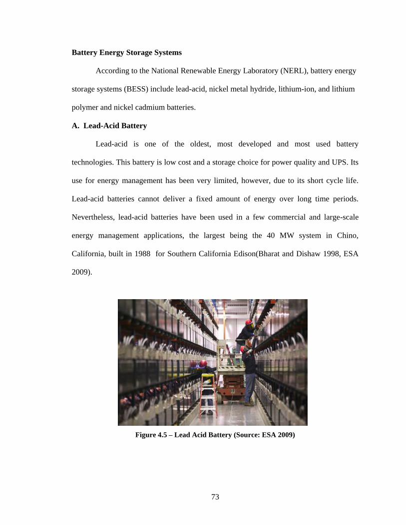
73
Battery Energy Storage Systems
According to the National Renewable Energy Laboratory (NERL), battery energy
storage systems (BESS) include lead-acid, nickel metal hydride, lithium-ion, and lithium
polymer and nickel cadmium batteries.
A. Lead-Acid Battery
Lead-acid is one of the oldest, most developed and most used battery
technologies. This battery is low cost and a storage choice for power quality and UPS. Its
use for energy management has been very limited, however, due to its short cycle life.
Lead-acid batteries cannot deliver a fixed amount of energy over long time periods.
Nevertheless, lead-acid batteries have been used in a few commercial and large-scale
energy management applications, the largest being the 40 MW system in Chino,
California, built in 1988 for Southern California Edison(Bharat and Dishaw 1998, ESA
2009).
Figure 4.5 – Lead Acid Battery (Source: ESA 2009)

74
Location on Grid
Lead-acid batteries have been installed on distribution feeders, and as UPS
backup systems for consumer-end applications in residential and commercial areas
(Dishaw 1998).
Development / Deployment Status and Existing Installations
There is ongoing research for adapting lead-acid batteries for commercial grid
applications. In 1998, Southern California Edison installed a 10MW lead-acid BESS at its
substation in Chino, California (Dishaw 1998, ESA 2009).
B. Lithium - Ion (LI-Ion) Battery
Lithium-ion batteries have a cathode that is a lithiated metal oxide (LiCoO2,
LiMO2, etc.); the anode is made of graphitic carbon in a layered structure. An electrolyte
of dissolved organic carbon and lithium salts (e.g., LiPF6) surrounds the anode and the
cathode. When the battery is charged, the lithium atoms in the cathode become ions and
migrate through the electrolyte toward the carbon anode, where they combine with
external electrons and are deposited between carbon layers as lithium atoms. This process
is reversed during discharge (ESA 2009).

75
Figure 4.6 – Li-ion Battery (Source: NASA 2010)
Location on Grid
Lithium-ion batteries are presently being used on distribution feeders, for power
quality applications, and have been adopted as UPS for industrial and commercial
applications.
Deployment Status Existing Installations
Li-ion batteries are expected to control over 50% of the small portable appliance
battery market in a few years. There are, however, some challenges to making large-scale
Li-ion batteries for commercial applications. The production costs and the need for
special packaging needs are problems that several companies are still working on (ESA
2009).
AEP is installing 80 lithium-ion batteries, as community energy storage systems, in the
northeastern part of Columbus, Ohio; this is to be completed in 2011(Atkins 2010)
76
Flow Batteries
Flow batteries are fuel cells that, by means of a reversible electrochemical
reaction between two electrolytes, store and release energy continuously at a high rate.
The main flow batteries are Vanadium Bromide (VRB), Zinc Bromide (ZnBr), and
Sodium Bromide (NaBr) batteries. All these batteries work on the same principle—the
bigger the tank, the more energy that can be stored (van der Linden 2006).
A. Vanadium Redox Battery (VRB)
The Vanadium Redox Battery (VRB) is a flow battery that uses liquid vanadium-
based electrolytes, stored in external tanks filled with electrolytes that flow into a
regenerative power cell, producing electric power electrochemically. A key advantage of
the VRB is that, by simply increasing the size of the electrolyte tanks, more energy can
be stored (Fabjan et al. 2001). The power rating is a function of the regenerative fuel cell
and its inverter. Flow batteries have a very low rate of internal discharge and parasitic
losses. The VRB has an estimated lifespan of more than 10,000 cycles. An issue with the
VRB is its relatively low volumetric energy density, thus it requires a sizeable footprint.
Improvements in the battery‘s membrane and electrolyte technologies are needed to
reduce VRB capital costs (ESA 2009, Fabjan et al 2001).
Some of the advantages of VRB over other storage systems are:
Long life with few disposal issues
High efficiency
Speed of response to waveform deviations
Rapid charge and discharge
Expandability

77
Figure 4.7. Vanadium Redox Battery Flow Schematic (Sources NETL 2009)
Location on Grid
The VRB is located at the generation and distribution feeders.
Deployment Status and Existing Installations
PacifiCorp installed a VRB Energy Storage System in Castle Valley, Utah in
2003(VRB 2007).
B. Zinc Bromide (ZnBr) Battery
This battery utilizes a circulation system to continuously feed reactants from
external reservoirs into the battery stacks. It is, therefore, classified as a "flowing
electrolyte," or flow battery. The stack contains a series of bipolar electrodes and porous
separators between two monopolar (one negative and one positive) terminal electrodes.
Electrolyte Electrolyte
Electrolyte
Tank Electrode
Electrolyte
Tank Ion-selective
membrane
Pump Pump Power Source/load
Regen
fuel
erative
cell
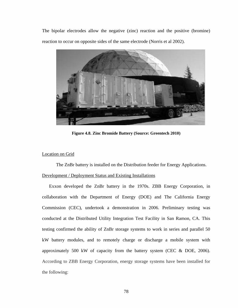
78
The bipolar electrodes allow the negative (zinc) reaction and the positive (bromine)
reaction to occur on opposite sides of the same electrode (Norris et al 2002).
Figure 4.8. Zinc Bromide Battery (Source: Greentech 2010)
Location on Grid
The ZnBr battery is installed on the Distribution feeder for Energy Applications.
Development / Deployment Status and Existing Installations
Exxon developed the ZnBr battery in the 1970s. ZBB Energy Corporation, in
collaboration with the Department of Energy (DOE) and The California Energy
Commission (CEC), undertook a demonstration in 2006. Preliminary testing was
conducted at the Distributed Utility Integration Test Facility in San Ramon, CA. This
testing confirmed the ability of ZnBr storage systems to work in series and parallel 50
kW battery modules, and to remotely charge or discharge a mobile system with
approximately 500 kW of capacity from the battery system (CEC & DOE, 2006).
According to ZBB Energy Corporation, energy storage systems have been installed for
the following:

79
Envinity (State College, Pennsylvania)
Oregon State University (Corvallis, Oregon)
Pacific Gas and Electric Company (San Francisco, USA)
Detroit Edison (Detroit, USA)
Sandia National Laboratories (Albuquerque, USA)
C. Metallic-air Batteries
Metallic-air batteries have been in utilized in fuel cells, with the use of Zinc
metal, for several years. To increase capacity, however, high density metals like Lithium,
Magnesium, and Aluminum are being explored for usage as the anode of the battery
(Armand & Trasacon 2008, ESA 2009). The cathodes or air electrodes are often made of
a porous carbon structure, or a metal mesh covered with catalysts. The electrolytes are
often manufactured of a good hydroxide (OH) ion conductor, such as Potassium
Hydrochloride. Metal-air batteries are compact and have the potential to be the least
expensive storage system. They have been deemed to be mostly environmentally safe.
However, charging and recharging the battery is deemed to be inefficient and expensive
(ESA 2009).

80
Figure 4.9. Metallic Air Battery (Source: General Motors 2010)
Location on Grid/Grid Application
The metallic air battery is located on the distribution feeder for energy application
Deployment Status and Existing Installations
Metallic-air batteries have the potential of being cheaper lightweight energy
storage due to their potentially high energy densities (Abraham 2008). The first metal-ion
battery was demonstrated in the early nineteen-nineties. Several ongoing research
projects are looking at adopting Metal-Air Batteries for commercial grid applications at
MIT and other institutions. There are no existing commercial installations for metallic-air
batteries.
Carbon
Lithium Ion
Lithium Oxygen
Compound Electron Flow
Negative
Electrode
Oxygen
Oxygen
Manganese
Oxide
(the catalyst)
Electrolyte
Positive Electrode

81
Community Energy Storage
This small distributed energy storage system is connected to secondary
transformers that serve a group of homes. Individual batteries can be used to provide
backup power to service individual homes or can be aggregated to work together as a
virtual backup storage system for the grid. CES is utilized for power quality deficiencies
and for the efficient integration of renewable resources (AEP 2009, Nourai 2010). In the
future, CES can be controlled through an integrated communications system, to be used
for demand response, in conjunction with PHEV on another part of the grid, as backup
power in times of emergency (AEP 2009).
Figure 4.10. Community Energy Storage (Source: AEP 2009)
Location on Grid
Community energy storage is installed on the distribution feeder for energy smoothing
and UPS applications.

82
Deployment Status and Existing Installations
Several utilities, like AEP and DTE, are deploying CES in limited quantities and
in demonstration. Several battery manufacturers are rolling out batteries of varying
capacities for use as CES. AEP is installing 80 lithium-ion batteries in northeastern parts
of Columbus, Ohio, to be completed in 2011(Atkins 201

83
Table 4.1 - Comparison of Storage Systems (Adopted from ESA 2009)
Energy Storage
Device Advantages (relative) Disadvantages (relative)
Power
Application*
Energy
Application* Remarks
Pumped Storage High Capacity, Low Cost Special Site Requirements
CAES High Capacity, Low Cost Special Site Requirements,
Need Gas Fuel
Flow Batteries: VRB
ZnBr, PSB
High Capacity, Independent
Power and Energy Ratings
Low Energy Density
Metal-Air Very High Energy Densities, Electric Charging is Difficult
NaS High Power & Energy
Densities, High Efficiency
Production Cost
Large Capacity
obtained by
connecting batteries
Li-ion High Power & Energy, High
Efficiency
High Production Cost,
Requires Special Charging
Circuit
Adoption for CES
Lead-Acid Low Capital Cost Limited Cycle Life when
Deeply Discharged
Flywheels High Power Low Energy Density, High
Production Cost
* Not Feasible or Economical Reasonable for Application Fully Capable and Reasonable

84
4.3.2 Advanced Superconducting Transmission Cables
Several advancements in cable technology have improved the ability to transport
electricity in high currents. Advance superconducting transmission cables can carry about
1.5-8 times the current capacities carried by steel core cables. Superconducting cables
will transport currents between 500kv-800kv, for both AC and DC applications. These
superconducting cables can transfer power with a 40% increase in efficiency, by
decreasing sag through reduced heating (Malozemoff et al 2008, Ulliman 2009).
Location on Grid
Transmission cables are located on the transmission section of the grid. The most
common advanced cables are (EPRI 2000, Ulliman 2009, and NETL 2009):
High Temperature Superconducting (HTS) Cables
This cable utilizes the ability of some conductors to have zero electric resistivity
when they are cooled below their critical temperature. HTS cables are cooled by liquid
nitrogen to their critical temperatures and are used to transport electricity. HTS cables
will allow existing substations to service increasing power requirements and reduce the
need for voltage transformation steps (EPRI 2000, McConnell 2005). HTS cables are
primarily suitable for direct current applications; it is especially advantageous for
underground installations, due to small trench requirements and less need for right-of-
way paths. As such, it is more economical for use in large population areas, to carry high
capacity power (McConnell 2005).
HTS are divided into first and second generation HTS cables, depending on their
construction properties (NETL 2009).

85
HTS cables have several advantages over traditional copper cables. The advantages of
HTS cables are (ORNL 2005, McConnell 2005, and Hirose et al. 2006):
Generates essentially no waste heat or electrical losses
Use of environmentally benign liquid nitrogen for cooling
Can be installed into existing conduit infrastructure
Takes up less space than conventional cables, leaving room for future expansion
A. First Generation HTS Cables (1G HTS)
First Generation HTS Cables (1G HTS) can be used to transmit high currents and
large power quantities, with little loss from heating in the conductor at lower voltages.
This low loss from heating allows the use of small trenches for underground applications
(ORNL 2005, NETL 2009),
Figure 4.11. Cross section of typical HTS cable (Source: EPRI 2000)

86
Deployment Status and Existing Installations
The 1G HTS cable is still in development; it is available in limited commercial
quantities. Due to its high cost, there is a manufacturing limitation. It is expected to be
widely available in about 1 year (NETL 2007c, NETL 2009).
SuperPower, Inc.—in partnership with Linde, Sumitomo Electric Industries, Ltd.
from Japan and National Grid—have designed, manufactured, and installed an
underground, high-temperature superconducting (HTS) power cable between two
National Grid substations in Albany, NY.
Figure 4.12 – HTS Underground Cables Connected to Transformer Substation
(Source: AMSC 2010)
B. Second Generation HTS Cables (2G HTS)
Over the past few years there have been rapid gains in the development of second
generation HTS (2G HTS) cables. A 2G HTS cable is achieved by the annealing of a
conductor with a high resistivity stabilizer, like Yttrium barium copper oxide (YBCO).
The wires are then laminated with copper, stainless steel, or brass metals, to provide

87
fortification, durability and certain electrical characteristics needed for several electrical
applications like power transmission. 2G HTS cables have the ability to carry 10 times
greater current than the regular copper cable of a similar cross section area (Malozemoff
et al 2008).
Deployment Status and Existing Installations
American Superconductor Corporation introduced their 2G HTS cables in a pre-
pilot version of the cables in 2005. 2G HTS is now available in limited quantities; it is
expected to be commercially available in the next few years ((Malozemoff et al 2008,
EPRI 2009, NETL 2009). There are no existing commercial installations of 2G HTS.
Aluminum Conductor Composite Core (ACCC®)
ACCC‘s strength as a conductor is achieved through a hybrid carbon and glass
fiber core, which is wrapped with trapezoidal-shaped aluminum strands. The high
strength structural core carries the electrical load, and the trapezoidal aluminum strands
carry the electrical current. The composite core of the ACCC conductor is much lighter
and about 40% stronger than conventional copper cable or high-strength steel core cable.
Its lighter weight allows the use of fewer transmission towers in carrying the equivalent
amount of load used by conventional conductors, and can incorporate about 25% to 30%
more aluminum (conductive material), without any additional weight. The fiberglass core
in the ACCC conductor prevents corrosion from galvanization. The conductor heats less
and, therefore, sags at a higher temperature than conventional cables. (Jones 2006,
Kopsidas & Rowland 2009, Ulliman 2009).

88
Figure 4.13 – Aluminum Conductor Composite Core. (Source: CTC 2010)
Deployment Status and Existing Installations
Composite Technology Corporation (CTC) introduced the ACCC cable in a
limited commercial application in 2006. The ACCC cable is now available commercially
(Jones 2006). In 2006, Utah Power used CTC‘s ACCC conductor to re-cable a 10-mile
transmission line. Since then, there have been several installations throughout the United
States and worldwide (Jones 2006, CTC 2009).
Annealed Aluminum Steel Support with Trapezoidal Wire (ACSS/TW)
Annealed aluminum steel support with trapezoidal wire (AASS/TW) is made of
trapezoidal wires wrapped around a steel core. Replacing the round wires with
trapezoidal-shaped wires created a more compact conductor, with the same metal area as
a traditional conductor, but less susceptible to ice and wind loading, due to its reduced
diameter (Thrash 1999). The annealed aluminum wire construction enables it to
continuously operate up to temperatures of 250 degrees with little sag, even though it
carries 32% more current (Ahmad et al 2005,NETL 2009).

89
Deployment Status and Existing Installations
The ACSS/TW conductor is commercially available; several companies market it
under different brand names. CenterPoint Energy was the first to install ACSS cables on
an 80 mile, 345kV transmission project in 2007(Harms 2007).
Aluminum Conductor Composite Reinforced (ACCR)
Aluminum Conductor Composite Reinforced (ACCR) relies on a composite core
of purified aluminum strands and ceramic fiber, surrounded by an outer strand made of
temperature-resistant aluminum zirconium cables (3M 2003). This build-up enables the
conductor to operate at temperatures of up to 240 degrees (3M 2003, NETL 2009).
Figure 4.14 Aluminum Conductor Composite Reinforced (Source: Solarsofa.com 2010)
Deployment Status and Existing Installations
ACCR is commercially available and has been installed on several projects
worldwide since 2001 (NETL 2007c). Hawaiian Electric installed a 477-kcmil Composite
Conductor on the North shore of the island of Oahu, Hawaii, to make use of the
conductor‘s corrosion-prevention properties against the oceanic conditions of the area
(3M 2003).

90
4.3.3 Grid-Tied Inverter (GTI)
A grid-tied inverter (GTI) is a special inverter used to integrate renewable energy
sources, like solar farms, with the AC grid. GTI is used to mitigate the intermittent
characteristics of renewable energy sources while it performs its primary function of
converting DC to AC (Ton and Bower 2005). There are two types of inverter systems:
those that connect PV cells directly to the grid, and those that connect PV cells to storage
devices, which are connected to the grid.
Figure 4.15– Grid-Tied Inverters (Source: wsetech.com 2010)
Location on Grid
A GTI is installed on the renewable generation connection to grid
Deployment Status and Existing Installations
GTI are commercially available and have been installed on several commercial
and residential renewable-energy-generation installations.
4.3.4 Smart Meters
The smart meter is an intelligent meter installed at residential premises and
commercial buildings. The meter is deemed to be ―smart‖ because it is able to perform

91
three main functions (Houseman 2005, van Gerwen et al 2006):
The ability to measure the electricity used (or generated)
The ability for the utility company to remotely switch the customer off
The ability to remotely control the maximum electricity consumption
The electric smart meter uses an internally installed modem to exchange
communications between the utility company and the customer. Data—e.g., the quality of
the power at the load source, the amount of power being used, the equipment in use,
electricity prices, and more—can be accessed through the use of Bluetooth technology,
Zigbee, Global Positioning System (GPS) or an existing internet connection between the
smart meter and existing home appliances or a home display (van Gerwen, et al 2006).
Smart meters are classified as both an advanced component, and a sensing and
measurement technology. More details of smart meters were presented as part of the
discussion of automated metering infrastructure (AMI) in section 4.4.8.
4.3.5 Demand Response Load Control Receiver
Demand response refers to mechanisms used to encourage consumers to reduce
demand, thereby reducing the demand for electricity. Since electrical generation and
transmission systems are generally sized to correspond to peak demand; lowering
demand reduces overall operation costs for utility and generation companies. There are
two types of demand response, based on the purpose: emergency demand response and
economic demand response. Emergency demand response is primarily needed to avoid
outages, while economic demand response is used to help utilities manage daily system
peaks (Schellenberg 2008).
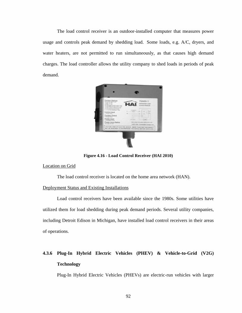
92
The load control receiver is an outdoor-installed computer that measures power
usage and controls peak demand by shedding load. Some loads, e.g. A/C, dryers, and
water heaters, are not permitted to run simultaneously, as that causes high demand
charges. The load controller allows the utility company to shed loads in periods of peak
demand.
Figure 4.16 - Load Control Receiver (HAI 2010)
Location on Grid
The load control receiver is located on the home area network (HAN).
Deployment Status and Existing Installations
Load control receivers have been available since the 1980s. Some utilities have
utilized them for load shedding during peak demand periods. Several utility companies,
including Detroit Edison in Michigan, have installed load control receivers in their areas
of operations.
4.3.6 Plug-In Hybrid Electric Vehicles (PHEV) & Vehicle-to-Grid (V2G)
Technology
Plug-In Hybrid Electric Vehicles (PHEVs) are electric-run vehicles with larger

93
batteries than hybrid gas electric vehicles, and have the capacity to drive 30-50 miles,
exclusively using electric power, switching to gasoline for longer trips. (Lazar et al
2008). There is ongoing research for adopting the 60 Hz electricity stored in the batteries
of PHEV as mini energy-storage devices, and deploying this power to respond to demand
hikes on the grid, as well as in utilizing large fleets of PHEV as sources of emergency
power (Denholm and Short 2006).
Figure 4.17 – Plug In Hybrid Electric Vehicle (Source: Blog.niot.net 2010)
Location on Grid
The PHEV is located on the Home area network (HAN) in either a residence or a
commercial charging station.
Deployment Status and Existing Installations
PHEV are now commercially available, several car companies are producing their
version of PHEV. However, utilizing PHEV batteries as backup energy storage systems
is in research.

94
4.3.7 Plug- In Electric Vehicles (PEV) Charging Station
These are commercial station where plug-in hybrid vehicles (PHEV) vehicles can
be charged. The charging stations usually meet a level 2 or 3 charging designation. Level
2 charging stations which is the most common type of charging station employs 240 V
AC and 40A current. The level 3 chargers will be fast charging employs a 480VAC
current a level three charger should be able to achieve 50% charge in 10-15 minutes
(DOE 2008).
Figure 4.18. PHEV Charging Station
Location on Grid
THE PHEV charging stations are located in the home area network either in a
residential setting or in commercial parking lots or commercial charging stations.
Deployment Status and Existing Installations
Level 2 PHEV chargers are commercially available; level 3 PHEV chargers
however are available in limited quantities commercially. Companies have started

95
installing commercial charging stations in several states around the country. 4.7 million
charge stations are expected to be installed by 2015 (Addison 2010).
4.3.8. Other Technologies
There are a number of other advanced component technologies. Some of these
technologies are summarized in table 4.2.
Table 4.2 Sample Advanced Component Technologies (Adopted from NETL 2009)
ADVANCED COMPONENTS
Technology Deployment
Status
Description References
Current
Limiting
Conductor
(CLiC)
2 years CLiC are modules that are attached to a
line or transmission tower. When CLiC
senses an overload in the conductor, it
uses magnetic induction to transfer
loads to more receptive parts of the
line, to prevent thermal overload on the
line. Georgia Institute of Technology
School of Electrical Engineering, in
collaboration with DOE and several
companies are developing CLiC.
http://ieeexplore.i
eee.org/stamp/sta
mp.jsp?tp=&arnu
mber=1668661&
userType=&tag=1
www.oe.energy.g
ov/Documentsand
Media/Intelligent
_Power_Infrastru
cture_Consortium
_Divan.pdf
D-VAR or
DSTATCO
M
Commercial
ly available
D-VARS can be sited on the
Transmission and Distribution
interfaces to provide voltage support.
D-VARS reduce voltage variations
through the use of transistors.
www.sgiclearingh
ouse.org/Technol
ogies?q=node/217
6
Advanced
Online Tap
Changer
(OLTC) for
Transformer
1-2 OLTC is used to change the tapping
connection of the transformer, winding,
to change the voltage ratio while the
transformer is still in service, without
interrupting the load.
Douglas. M.
Getson. On-load
Tap Changers.
Document
updated: 2002-
11-06.
http://ieeexplore.i
eee.org/stamp/sta
mp.jsp?tp=&arnu
mber=1047553
Static VAr
compensato
r (SVC)
Commercial
ly Available
SVC provides fast-acting reactive
power on high voltage transmission
networks (De Kock and Staruss 2004).

96
4.4. SENSING AND MEASUREMENT
Sensing and measurement technologies receive and convert information from
components into data. These technologies check the operation quality of the individual
components and the grid as a whole. The smart meter and the home area network
(HAN), which are expected to enable demand response (DR), are the most widely
anticipated changes for the customer end of the grid. At the utility and transmission
levels, several wide-area monitoring systems, like line sag meters, are being employed at
the transmission and distribution ends of the grid. These advanced sensing measurement
tools will track and transmit data to power system operators (NETL 2007b). There are
several technologies available now on the market, but adaptation has been hindered by
acceptance.
This section discusses the following sensing and measurement technologies:
RF temperature and Current Sensor for Conductors
Line Tracker Community Meter
Line Sag Monitors
Phasor Measurement Units
Wide Area Monitoring Systems (WAMS)
Substation Automation Sensors
Advanced Metering Infrastructure (AMI)
Smart Meters
Home Area Networks (HAN)
Home/Consumer Gateway

97
Miscellaneous Technologies
4.4.1. RF Temperature and Current Sensor for Conductors
This sensor records the transmission temperatures and current magnitudes on the
overhead transmission or distribution conducting cables, and transmits the data to control
stations wirelessly (EPRI 2009).
Figure 4.19 – RF Temperature and Current Sensor (Source: EPRI 2009)
Deployment Status and Existing Installations
This sensor is being developed by the Electric Power Research Institute (EPRI)
and is under demonstration.
4.4.2. Line Tracker Communicating Meter
The line tracker communications device is used to record fault currents and load
profiles. This will help in quick responses to outage detection and restoration.

98
Figure 4.20. Line Tracker (Source: GridSense 2010)
Deployment Status and Existing Installations
The Line Tracker is being developed by EPRI. This technology is available in limited
quantities.
4.4.3. Line Sag Monitors (Sagometer)
This is a device installed on the transmission tower to monitor cable sag on
overhead transmission cables in real time, and to communicate the results via a
communication station. The Sagometer was developed by EPRI and has been
commercialized by EDM (EPRI 2009).
Figure 4.21 – Schematic Layout of Sagometer Setup (Source: EDM 2010)
Target
Datalogger &
Communications
Smart
Camera
Optional
Meteorological
Station

99
The Sagometer is mounted on one of the supporting structures of the span to be
monitored. The smart camera is aimed down the span, on a target attached to one of the
conductors. The smart camera measures the sag clearance; this information is then
communicated in real time to the control monitoring station, through wireless or radio
frequencies (EDM 2008).
Figure 4.22– Sagometer (Source: EDM 2010)
Development / Deployment Status and Existing Installations
Sag meter monitors developed by EPRI are under demonstration, in limited
commercial quantities, through EDM International in Colorado.
4.4.4. Phasor Measurement Units
These are high-speed sensors that are used to monitor power quality and to
automatically respond to changes in voltage quality in real time. This technology can
detect and represent the instantaneous capacity factor and the phase angle of the current.
Once this data is known, it can be precisely monitored and disseminated to control
centers for action. The harmonious and efficient integration, via PMU, is a prerequisite
for feeding renewable and decentralized energy generation, e.g. from wind turbines of

100
varying sizes, into large networks, thus ensuring an efficient and, above all, reliable
supply of renewable energies (Energynautics 2009).
Figure 4.23. - Phasor measurement unit (Source: EPL 2010a)
Location on Grid
The PMU is can be located on both the generation and distribution Substations
Deployment Status and Existing Installations
PMU are commercially available. They have been installed in several substations
as part of the utilities companies‘ distribution management systems (DMS).
4.4.5. Wide Area Monitoring System (WAMS)
Wide Area Monitoring Systems (WAMS) continuously monitor power by
utilizing synchronized phasor measurements that can stream data in real time. The
WAMS help in fault detection and isolation. Though several utilities in the US have
deployed PMU networks widely, impediments still exist, such as cost and reliability in
implementing WAMS systems (NETL 2009). WAMS utilize GPS technology to give
every phasor measurement a time and location stamp for easy fault location and tracking.

101
Most of the existing WAMS utilize several existing communication protocols. WAMS
will be most effective when the monitoring capacity of the system is no longer limited to
the area of operation, but covers the whole grid (Hadley et al. 2007).
Location on Grid
WAMS are installed on transmission feeders.
Deployment Status and Existing Installations
Commercially available in limited quantities in the western United States.
4.4.6. Substation Automation (SA) Sensors
To fully realize the advantages of smart electric grids, transmission and
distribution substations will have to be fully automated and able to relay information
between generation and distribution sources, and between distribution sources and the
end-users of electric power. A substation can be made ‗smart‘ through the installation of
intelligent electronic devices (IEDs) in its basic components, to enable both quick
detection and correction of faults in the grid, and communication among the various
components of the power grid.
For a substation to be considered smart, the following main components will have
to be upgraded with IEDs:
Transformers
Circuits Breakers
Relaying and Protection Equipment
Optical Measuring Systems
Station Batteries

102
Superconductors
Substation Information Technology, and Supervisory Control and Data
Acquisition (SCADA)
Substation-Wide Antenna Arrays
This technology continuously monitors and accurately locates partial discharges
of the substations‘ failing components through a fixed antenna array (EPRI 2009).
Figure 4.24 - Antenna Array (Source: EPRI 2009)
Development / Deployment Status and Existing Installations
This sensor is under demonstration.
Transformers
The transformer, which serves as the hub for collection and distribution of
electrical energy, will have to be made ―smart‖ by installing sensors to collect and
communicate data on the power network. The basic working mechanics of the
transformers have not changed much. The additional capabilities will be in analyzing

103
voltage and current flow. This will, in turn, enhance the efficiency of the grid (Pacific
Crest 2009)
Location on Grid
Smart transformers are installed in generation and distribution substations
Transformer Tanks
EPRI is conducting research on the development of a transformer tank and continuous oil
filtration system with the ability to maintain transformer oil in ―as-new‖ condition over a
long period of time. This will prevent the broken down chemicals in the oil from
affecting the transformer, thereby maintaining the integrity of the complete dielectric
system in the transformer (EPRI 2001).
Development / Deployment Status and Existing Installations
A sensor developed by EPRI is under demonstration.
Transformer-Metal Insulated Semiconducting (MIS) Gas in Oil Sensor
The MIS sensor is a low-cost hydrogen sensor on a chip. There was a recent
breakthrough in its development and in field demonstrations in transformers. This chip,
which will be installed in the transformer, will detect hydrogen emissions in the tank and
relay these measurements. These will then be sent wirelessly to the control centers of the
utility or generation companies. The hydrogen determines the emission level, which can
be monitored to determine the probability of repair needs in a transformer (EPRI 2009).

104
Figure 4.25. Transformer-Metal Insulated Semiconducting (MIS) Gas in Oil Sensor
(Source: EPRI 2009)
Deployment Status and Existing Installations
This sensor, developed by EPRI, is under demonstration.
Transformer-On-Line Frequency Response Analysis (FRA)
The FRA was developed to measure the response of a transformer to faults in the
systems, which are normal occurrences in grid operations (e.g. switching or lighting). The
internal geometry of a transformer or other components of a substation (circuit breakers,
insulators, disconnect switches, control equipment) can be identified by changes in the
frequency response (EPRI 2003, EPRI 2009).
Development / Deployment Status and Existing Installations
This sensor is currently in demonstration.
Fault Current Limiting High Temperature Super Conducting Transformers
Fault current limiting high temperature superconductor (HTS) transformers
employ the use of HTS conductors as coils, with liquid nitrogen to cool and insulate the
coils in the transformer. These features make the transformer more efficient by reducing
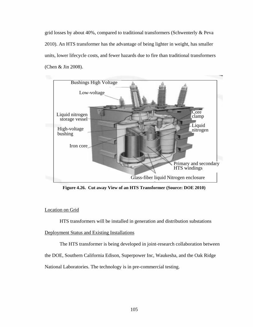
105
grid losses by about 40%, compared to traditional transformers (Schwenterly & Peva
2010). An HTS transformer has the advantage of being lighter in weight, has smaller
units, lower lifecycle costs, and fewer hazards due to fire than traditional transformers
(Chen & Jin 2008).
Figure 4.26. Cut away View of an HTS Transformer (Source: DOE 2010)
Location on Grid
HTS transformers will be installed in generation and distribution substations
Deployment Status and Existing Installations
The HTS transformer is being developed in joint-research collaboration between
the DOE, Southern California Edison, Superpower Inc, Waukesha, and the Oak Ridge
National Laboratories. The technology is in pre-commercial testing.
Glass-fiber liquid Nitrogen enclosure
Primary and secondary HTS windings
Liquid nitrogen
Core clamp
Iron core
High-voltage bushing
Liquid nitrogen storage vessel
Low-voltage
Bushings High Voltage

106
Transformer 3-D Acoustic Emissions Technique
This enables the detection and location of gassing sources in power transformers,
through monitoring the partial discharges in the transformer (EPRI 2009, Nagamani et al
2005)
Figure 4.27. 3D Acoustic Monitor (Source: EPRI 2009)
Location on Grid
Transformer 3-D acoustic monitor is installed in the power transformers on the
generation and distribution substations
Deployment Status and Existing Installations
Technology under demonstration by EPRI, and is being tested in limited commercial
quantities with some companies.
According to EPRI, the following additional technologies are being researched
(2009):
Cost-effective high temperature insulating fluid
Superconducting windings
A non-mechanically driven load taps changer
A transformer life assessment model
Development of a prototype transformer with superconducting windings

107
Circuit Breakers
Radio Frequency (RF) SF6 Density Sensors
Sulfur Hexafluoride (SF6) is a gaseous dial electric gas used for insulation in
circuit breakers. The sensor measures the density of the SF6 gas and transmits the results
wirelessly (EPRI 2009).
Deployment Status and Existing Installations
This sensor, developed by EPRI, is under demonstration.
Optical Measuring Systems
Substation-Wide Online Infrared
This system uses ultrasound sensing with visual and infrared video, for
continuous online monitoring of the substation by the installation of infrared
thermographic cameras. The online monitor alerts the utility or generation companies to
detected deviations in substation heating over the network (EPRI 2009).
Figure 4.28 – Mikron Infrared Substation Camera (Source: EPL 2010b)
Deployment Status and Existing Installations
This sensor is under demonstration.
108
4.4.7. Advanced Metering Infrastructure (AMI)
According to Valigi & Di Matteo (2009) ―Advanced Metering Infrastructure
(AMI) refers to a system that measures, collects and analyzes energy usage, from
advanced devices such as electric smart meters, through various communication media,
on request or the basis of pre-defined schedule.‖ AMI utilizes two-way communications
to achieve these functions (EPRI 2007, Hart 2008).
AMI is an integration of several technologies. It consists of four main
components: a meter at the customers‘ location; a communications network between the
utility company and the smart meter the home area network; and the data management
software at the utility, to track and control the communication and electric flow, as well
as to serve as an interconnection to automated utility billing between the utility company
and the consumer (EPRI 2007, Hart 2008). More technologies can be built into the
systems, like GIS and data management applications.
AMI enables the utility company to undertake demand-response remotely at the
customer level, and gives the consumer the ability to make informed decisions (NETL
2008). The home area network gateway reads and ties the meter into various end-use
devices, and communicates with the service provider.
AMI is often confused with automated meter reading (AMR). AMI entails more
than just the automated reading of meters. Table 3.3 shows the differences between AMI
and AMR.
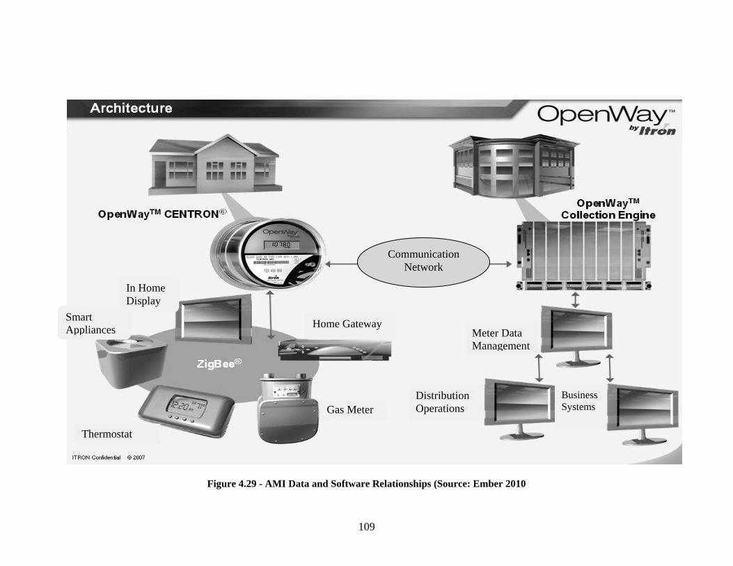
109
Figure 4.29 - AMI Data and Software Relationships (Source: Ember 2010
Communication
Network
Smart
Appliances
In Home
Display
Home Gateway
Gas Meter
Meter Data
Management
Distribution
Operations
Business
Systems
Thermostat
110
AMI, through the communications network, has the ability to transport control
signals and prices to the smart meter, and to collect data from the home through the smart
meter and send it to the utility company (Hornby et al 2008).
The most common AMI Communication Protocols used are (Bennett 2008):
Radio Frequencies
Z-Wave with 802.15
ZigBee with 802.15
WiFi with 802.11
Bluetooth SIG with 802.11
Low Power Wireless Area Network 6loWPAN with 802.15
LonWorks
Deployment Status and Existing Installations
AMI deployment is ongoing among several US utility companies.
4.4.8. Smart Meters
The smart meter is an intelligent meter installed at residential premises and
commercial buildings. According to van Gerwen et al (2006), the meter is deemed to be
―smart‖ because it is able to perform three main functions: tracking the electricity used;
allowing the utility companies to remotely control appliances on the home area network;
and allowing electricity consumption to be controlled remotely. Smart meters are

111
combined with wide area communications infrastructure and meter management systems
(MDMS) (NETL 2008).
Table 4.3. Comparison of AMI and Manual Meter Reading and AMR
(Developed form van Gerwen et al 2006)
Manual/AMR AMI
Pricing None
Total consumption
Time-of-use
Critical peak pricing
Real-time pricing
On Demand
Response
Monthly bill
Load control
Demand bidding
Demand reserves
Critical peak rebates
Customer
Feedback
Turn off appliances manually
Monthly bill
Monthly detailed report
Web display
In-home display
Customer Bill
Saving
Customer phone calls
Turn off appliances
Shift appliances off-peak
Manual or automatic control
Outages Automatic detection
Verification of restoration at individual
home level
Distribution
Operations
Use engineering models
Dynamic, real-time operations
The electric smart meter uses an internally installed modem to exchange
communications between the utility company and the customer. Data—such as the
quality of the power at the load source, the amount of power being used, the equipment in
use, electricity prices, etc.—can be accessed through the use of a communications
technology like Bluetooth, Zigbee, Global Positioning System (GPS), an existing internet
connection between the smart meter and either existing home appliances or a home
display (van Gerwen et al 2006).

112
Appliances can be controlled directly and the display can be used to show historic
energy data, and energy cost and usage.
Figure 4.30. Smart Meter (Source: SmartSynch 2010)
Deployment Status and Existing Installations
About 70% of utility companies surveyed by GTM Research regarded smart
meters as a matter of high or highest priority for installation between 2010 and 2015, and
87% of top management at utility companies had assigned special priority to smart grid
initiatives (GTM Research 2010). This survey revealed that smart meter deployment is a
priority for most utility companies and that they see smart grid metering as the future of
energy distribution.
By the end of 2015, about 60 million smart meters will have been installed
nationwide (IEE 2010). Several utility companies in the United States are at various
stages of planned deployment for smart meters (Figure 4.35)
Meter Base SmartSynch
AMI/Intelligence
Module
Meter
Module
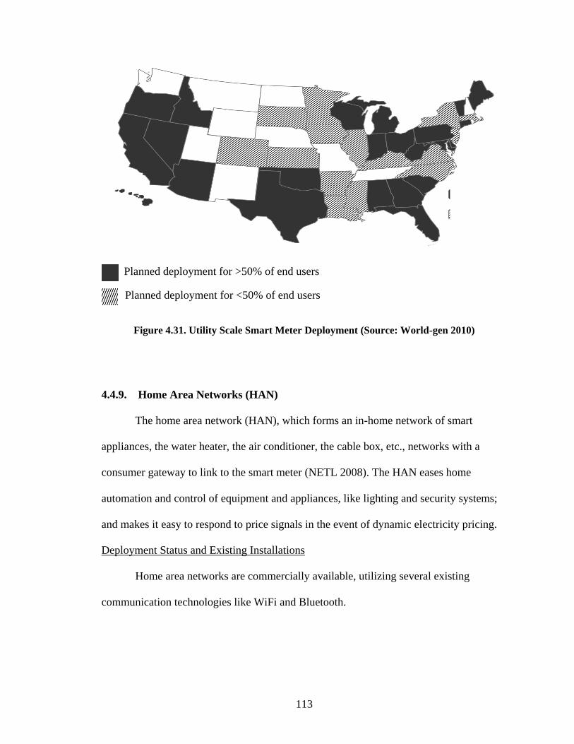
113
Planned deployment for >50% of end users
Planned deployment for <50% of end users
Figure 4.31. Utility Scale Smart Meter Deployment (Source: World-gen 2010)
4.4.9. Home Area Networks (HAN)
The home area network (HAN), which forms an in-home network of smart
appliances, the water heater, the air conditioner, the cable box, etc., networks with a
consumer gateway to link to the smart meter (NETL 2008). The HAN eases home
automation and control of equipment and appliances, like lighting and security systems;
and makes it easy to respond to price signals in the event of dynamic electricity pricing.
Deployment Status and Existing Installations
Home area networks are commercially available, utilizing several existing
communication technologies like WiFi and Bluetooth.

114
4.4.10. Home/ Consumer Gateway
The home gateway is the equipment that connects the home area network (HAN)
to the smart meter. The consumer portal is a combination of software and hardware that
enables communication between utilities and the consumers‘ end components (EPRI
2005). The gateway enables communication between the HAN and the smart meter,
through a communication protocol like Zigbee or Wi-Fi. The gateway can be a
standalone system, or installed in a smart meter, a media server or a cable box (Berst
2009).
Using a portal, a customer can receive information on power consumption and its
costs in real-time; view energy savings through demand response; report trouble with
service; and choose load response prices (EPRI 2005).
Figure 4.32 – Home Gateway (Source: Smartgridnews 2010)
Deployment Status and Existing Installations
Several consumer portal technologies are now available. Other portal
technologies, like Zigbee and Z-Wave, will be available in 2-3 years. EPRI is conducting
substantial work in this area.

115
4.4.11. Other Technologies
There are a number of other sensing and measurement technologies in the
research stage. Some of these technologies are summarized in table 4.4.
Table 4.4. Sample Sensing and Measurement Smart Grid Technologies
(Adopted from NETL 2009).
SENSING AND MEASUREMENT
Technology Deployment
Status
Description References
Dynamic Line
Rating
Technology
In research This technology measures the ampacity
over overhead transmission lines in real
time. There is ongoing research to
include line sag, current line capacity
and thermal line ratings over lines.
(NETL
2009)
Conductor/
compression
connector sensor
In research by
EPRI
This uses either wireless or broadband
technology over power lines (BPL) to
measure the dynamic ratings of
overhead transmission cables. It
measures the temperature differences
between the conductor and conductor
splices.
(NETL
2007b,
NETL
2009)
4.5. ADVANCED CONTROL METHODS
―Advanced Control Methods (ACMs) are the devices and algorithms that will
analyze, diagnose, and predict conditions in the modern grid, and determine and take
appropriate corrective actions to eliminate, mitigate, and prevent outages and power
quality disturbances (NETL 2007d).‖ ACM technologies will measure, analyze and
diagnose data, and autonomously respond to system faults. ACM, in its advanced stage,
is expected to collect and monitor grid components and data; analyze the collected data;
diagnose and solve emerging problems on the grid; take autonomous actions to rectify
anomalies; and provide information for operators to help in decision assistance (NETL
2007d).

116
This section discusses the following advanced control methods technologies:
Grid Friendly Appliance Controller
Substation SCADA
4.5.1. Grid Friendly Appliance Controller
Appliances that have been fitted with the Grid Friendly Appliance controller,
developed at the Pacific Northwestern National Laboratory (PNNL), sense grid
conditions by monitoring the frequency of the system, and provide automatic demand
response in times of disruption. Within the North American power grid, a disturbance of
60-Hz frequency is an indicator of a serious imbalance between supply and demand that,
unchecked, will lead to a blackout. This computer chip can be installed in household
appliances and will turn them off for a few minutes, or even just a few seconds, to allow
the grid to stabilize. The controllers can be programmed to autonomously react in
fractions of a second when a disturbance is detected. (PNNL 2002)
Figure 4.33. Grid Friendly Appliances (Source: PNNL 2010)

117
Location on Grid
Grid friendly controllers are installed in appliances on the Home area network
(HAN).
Deployment Status and Existing Installations
Grid friendly appliance controllers were developed by EPRI and are being
introduced by most appliance makers. In April 2009, Whirlpool announced that it will be
making all appliances smart grid compatible by 2015. The company set a goal of
producing 1 million smart dryers by 2011 (Greenbeat 2009).
4.5.2. Substation Information Technology, and Supervisory Control and Data
Acquisition (SCADA)
Figure 4.34. Substation SCADA communications system (Source:Tepco 2010)
Several companies, including IBM, Intel, Cisco, General Electric, and others,
have developed information and communications software, which monitor substations
SCADA System
Distribution Substation
(unmanned)
Transmission Substation (unmanned)
Distribution Substation
(unmanned)
Distribution Substation
(unmanned)

118
and deliver real time information to the utility companies, using data collected from the
different IEDs on the substation. They apply software, like the Geographical Information
Systems (GIS), to remotely identify and solve faults in the substation.
Location on Grid
SCADA systems are located grid wide on generation, transmission or distribution
feeders.
Deployment Status and Existing Installations
Different SCADA systems are commercially available and utilize different
communication technologies.
4.5.3. Other Technologies
There are a number of other sensing and measurement technologies. Some of
these technologies are summarized in table 4.5.

119
Sample of Advanced Control Methods for Smart Grid Technologies (Adopted NETL 2009)
ADVANCED CONTROL METHODS
Technology Deployment
Status
Description References
Advanced SCADA Commercially
Available
Advanced Control System‘s PRISM TM SCADA includes additional functions to the
standard SCADA system, like alarms, tagging, load management and load forecasting.
http:www.acsatlanta.c
om
Fault Locator for
Distribution Systems
2-5 years This system will determine the location of faults on the grid, using travelling waves.
This technology is being used on transmission grids but, due to its high cost, it has not
been transferable to distribution grids.
(NETL 2007d).
(NETL 2009).
Weather and Load
Forecasting–Numeric
Weather Prediction
(NWP)
Commercially
Available
There are several types of weather and load forecasting systems. The most common
ones are all available commercially: Artificial Neural Network (ANN), Fuzzy Logic,
Numerical Weather Prediction (NWP), Ensemble and Nowcasting.
(NETL 2009)
Grid Shock Absorber 3-5 years This concept is based on reconfiguring large interregional networks into
asynchronously operated sections. AC sections will be interconnected with HVDC
sections of the grid.
(Clark et al 2008)
Wide Area
Measurement
Systems(WAMS)
In service in
the West
WAMS continuously monitors power by utilizing synchronized phasor measurements
that can stream data in real time. Though PMU networks have been deployed widely
by several US utilities, there have been impediments such as cost and reliability in
implementing WAMS systems.
(NETL 2009),
www.naspi.org/
Distribution
Automation
Commercially
Available
This technology provides real time configuration of distribution equipment to prevent
power outages through the integration of smart sensors and integrated
communications.
(NETL 2007d, NETL
2009).
Real-Time Voltage
Stability
1-3 years This deploys reactive power reserves away from critical points in time, in the presence
of low load stability margins. These calculations will be derived from PMUs and load
characteristics.
(NETL 2009)
http://www2.selinc.co
m/techpprs/6224_Sync
hrophasorBased_YG_
20070607.pdf

120
4.6. INTEGRATED COMMUNICATIONS
These are fully integrated two-way communication technologies, which will make
the grid a dynamic interactive system for power and real-time data exchange (NETL
2007e, Roncero 2008). A variety of communication technologies are utilized in today‘s
grid, but most of these lack full high-speed communications integration. To be most
effective, the integrated communications protocol will have to achieve universality,
integrity, ease of use, cost effectiveness, standards, openness, and security (NETL
2007e). No universal standards for AMI and Demand Response (DR) exist yet. Several
committees and trade groups are collaborating to determine standards for integrated
communications systems. The NIST has been charged to develop such standards.
This section discusses the following the integrated communications technologies:
Broadband over Power Line
Wireless Technologies
Miscellaneous Technologies
4.6.1. Broadband over Power Line
The idea of broadband over power lines (BPL) has been used over several years
by utility companies for remote metering and control (Galli et al 2003). BPL is now being
utilized to meet utilities distributed-energy needs, which now include automated meter
reading (AMR), AMI and consumer portal applications (NETL 2007e).

121
4.6.2. Wireless Technologies
A variety of wireless technologies that may be utilized for electricity transmission
and distribution have been emerging over the past few years. The most common wireless
technologies, according to the NETL (2009), are:
Multiple Address System Radio
Paging Networks
Spread Spectrum Radio Systems
WiFi
Wimax
3Generation Cellular
Time Division Multiple Access (TDMA) Wireless
Code Division Multiple Access (CDMA) Wireless
Very Small Aperture Terminal (VSAT) Satellite
Most of these communication technologies are being used in different
applications. Some, like multiple address system radios, are being used by utilities.
4.6.3. Miscellaneous Technologies
There are several communication technologies that, even though they are not
wireless, could be utilized for grid-integrated communications. According the NETL
(2009), these are:
High Speed Internet
Power Line Carrier
Fiber to the Home (FTTH)

122
Hybrid Fiber Coax (HFC) Architecture
Radio Frequency Identification (RFID)
For smart grids to be successful, a fully integrated communication system will
need to be employed to enable two-way communication between utility companies and
consumers.
4.7. IMPROVED INTERFACES AND DECISION SUPPORT
IIDS will be the human interface software of the smart grid. IIDS technologies
will convert complicated power system data into easy-to-use information, to aid decision
making support. The IIDS will have two-way communication capabilities, where it will
be able to send and receive data from the customer, to aid decision-making both at the
utility and the HAN (NETL 2007f). When fully integrated into the grid, IIDSs will adopt
the use of artificial intelligence to optimize the utilization of grid assets through the
reduction of stress on the grid, thereby reducing power outages (NETL 2007f).
4.7.1. Geographic Information Systems (GIS)
Geographic information system use will be paramount to the tools for tracking
and responding to electric transmission and distribution. GIS can be used in any part of
the smart electric grid, from siting analysis of renewable energy sources to AMI
installation, monitoring and fault detection (ESRI 2009). The use of GIS is widespread in
the T&D industry in several capacities. The next generation of GIS is expected to
incorporate 3rd
and 4th
generation multi-dimensional information with the addition of
virtual reality.

123
Location on Grid
GIS can be utilized grid wide on generation, transmission or distribution feeders
for monitoring and tracking.
Deployment Status and Existing Installations
GIS map displays, for special analysis and measurements, are currently available
for widespread application over all sectors of the T&D industry. 3-D and 4-D GIS
visualization and modeling is expected to be available for commercial applications in
about a year (NETL 2009).
4.8. SUMMARY
This section provided a detailed overview of smart grid technologies. The
technologies were categorized under advanced components, sensing and measurements,
advanced control methods, integrated communications, and improved interface and
decision support. The technologies were discussed considering a broad overview, their
locations on the grid, and the deployment status and any existing installations. For
additional details of smart grid technologies, readers can refer to DOE-
Smartgridclearinghouse (2010), NETL 2009 and IEEE (2010). This overview of existing
and upcoming technologies will help determine the work scope of EC and aid in
determining construction opportunities inherent in the adaptation of smart grids.

124
CHAPTER 5
INSTALLATION AND CONSTRUCTION MANAGEMENT ASPECTS OF
SMART GRIDS
5.1. OVERVIEW
This chapter will explore the installation and construction management (CM)
aspects of five smart grid-related technologies: smart substation and smart transformers,
automated metering infrastructure (AMI), advanced superconducting transmission cables,
energy storage devices, and home area networks (HAN).
These installation and CM aspects will be considered in relation to the categories
of Impact on the Overall Power System Design; Location, Planning, Zoning and
Environmental Considerations; Product Procurement; Product Installation; Design and
Construction of Supporting Components; and Construction Project Management
Utility Construction Costs
Utility companies are expected to increase investments into transmission,
distribution, and generation over the next few years to match demand growth as predicted
by the Energy Information Administration (EIA) and the North American Electric
Reliability Corporation (NERC). The power-sector companies are forecasted to invest
about $11 trillion by 2030 (Stavros, 2007). This forecasted increase will usher in several
opportunities for the development and construction industry. However, there has been a
significant increase in the construction costs for utility infrastructure over the past few
years. According to Chupka and Basheda (2007) these increased costs result from
increases in:

125
The cost of raw materials,
The cost of construction field labor, and
The market conditions for engineering, procurement and construction (EPC).
This increase in the cost of delivering infrastructure projects is seen as a threat to
consistent investment into infrastructure construction, especially as governments are
cutting their construction budgets worldwide. These cost escalations are expected to
continue as demand for utilities infrastructure increases in developing countries and the
need to replace aging infrastructure continue in the developed world (Chupka & Basheda,
2007). The skills needed for sound construction management and installation practices
will need to be hired at a premium as labor scarcity and material costs keep escalating.
The advent of smart grids has seen several financial inflows into the power sector
as discussed in Chapter 3. For the implementation of smart grids to be successful and
self-sustaining, best construction and installation practices will be a factor in curbing cost
and time over-runs. In this study, the following five main smart grid technologies were
identified for in-depth analysis:
1. Smart Substation and Smart Transformer,
2. Automated Metering Infrastructure (AMI),
3. Advanced Superconducting Transmission Cables,
4. Energy Storage Devices, and
5. Home Area Networks.
After interaction and discussion with the members of the ELECTRI-NECA task
force and case study participants, these five technologies were chosen for their perceived

126
importance to the success of the implementation of smart grids. In addition, these five
technologies were selected to be able to complete this research within the scope of a
master‘s thesis.
In this chapter, the installation and construction management issues of the above
technologies will be categorized under the following broad sections for each technology:
1. Impact on Overall Power System Design
2. Location, Planning , Zoning and Environmental Considerations
3. Product Procurement
4. Product Installation
5. Design and Construction of Supporting Components
6. Construction Project Management
Based on the discussion of the chosen categories, the related work scope for electrical
contractors will be compiled as a matrix for each technology.
Location, Planning, Zoning, and Environmental Considerations
The locational and environmental considerations covered in this section are
common to a majority of the technologies to be discussed. Specific siting and
environmental considerations will be presented in relation to the various technologies in
later sections. The common location, planning, and environmental aspects that apply to
all technologies include public opposition, regulatory roadblocks, and environmental
constraints.
Public opposition.
Public opposition to siting renewable energy installations, transmission facilities,
and, by extension. smart grid components is considered to be one of the main barriers to

127
new development. NIMBY (not in my backyard) and BANANA (build absolutely
nothing anywhere near anything) has become part of the national vocabulary (Vajjhala
2006).
For renewable projects to succeed, public participation needs to be sought from
inception of the project. The benefit of a large public work cannot be fully realized
without public trust and support (Gale & O‘Driscoll, 2001). Due to negative views of
aesthetics and environmental problems, communities who are seemingly environmentally
conscious are more likely to accept traditional energy facilities than renewable
installations.
Regulatory Roadblocks:
Regulation of renewable energy and smart grid components is fragmented over
several agencies and departments. There is no standardized permitting and licensing
process, and project reviews can be done under the jurisdiction of federal, state, and local
governments. As an example, electricity transmission siting is regulated by the states and
some local authorities, while pricing is regulated by the federal government through the
Federal Energy Regulatory Commission (FERC). Regulating the siting of transmission
lines is the responsibility of the state; however, if the transmission lines cross state lines
then each individual state needs to approve the siting according to its own laws.
Additional federal approvals are needed if the lines cross federally owned or controlled
lines (Mayer & Sedano, 2006). These federal approvals, depending on the type of federal
land the transmission line is situated on, can be obtained from any one of the following
entities: the FERC, the Bureau of Land and Management under the Environmental
Protection Council (EPA), or the US Forest Service. Some projects are delayed
128
unnecessarily due to regulators‘ lack of familiarity with renewable energy installations
and smart grid components technologies (Vajjhala 2006).
Environmental Constraints:
Environmental constraints arise as a result of the fact that all construction projects
have some effect on the environment, and transmission/distribution lines and renewable
energy installations are no exception. The constraints on the environment can be
categorized under land use, electric and magnetic fields, and air emissions (Gale &
O‘Driscoll, 2001; Vajjhala, 2006). Renewable energy sources are highly dependent on
the available resources; for example, a wind farm will have to be sited where the wind
blows. Even though it might meet all other necessary requirements, this wind farm cannot
be replaced with a solar installation if the original proposal fails (Vajjhala 2006).
Renewable projects are also constrained by their access to supporting
transmission lines. Most of the prime areas for wind turbines are in the upper Midwest
where transmission lines are limited. The site-specific nature of renewable resources
might require some compromise when choosing between the highest quality resource
location and the location with the most reasonable cost due to the proximity of
infrastructure elements such as transmission lines (McVeigh et al. 1999).
5.2. ENERGY STORAGE DEVICES
Energy storage devices (ESD) are seen as major components in the success of
smart grids. Most ESD installations are pilot programs. However, these installations are
becoming increasingly widespread over the country. The installation processes
considered for ESD in this section are mostly for distribution feeder ESD, but are

129
relevant for most ESD. Some storage devices such as CAES and pumped hydro are too
large to fit on distribution feeders. Thus, only a few storage technologies like lead-acid
batteries, sodium sulfur (NaS), flywheels, and the like can be used for distribution
installations.
On the distribution feeder, the distributed voltage from the ESD should be
equivalent to the line ratings to and from the distribution feeder (Nourai, 2007). The
installation of ESD on distribution feeders includes the installation of the ESD together
with a power conversion system and a transformer to smooth incoming and outgoing
power. There is ongoing research to adopt larger forms of distribution capable battery
systems for the transmission feeder.
5.2.1. Impact on the Overall Power System Design
The widespread use of ESD on the grid will enable the storage of power during
off-peak periods for demand when demand is at its peak. This will enable utility
companies and consumers to reduce electric costs through the reduction of the size of
generation plants built specifically to meet peak demand requirements.
5.2.2. Location, Planning, Zoning, and Environmental Considerations
As with most new technologies, ESD have no history to guide regulators in their
installation and operation. There are few regulations explicitly for ESD installation (EAC
2008). ESD have the ability to operate as a generation source when used for generation
shifting and for power quality augmentation. These multiple roles have also led to
confusion about how ESD should be regulated (EAC 2008).

130
Nevertheless, the siting and location of ESD are critical in the installation of a
storage device. In times of emergency on the grid, the storage battery will be expected to
provide emergency power to serve critical infrastructures. This makes installing the ESD
to withstand disaster situations like floods, storms, and earthquakes critical.
Installed batteries are unusually installed near or in substations. The site selection
requirements are similar to those used for substation installation. The requirements are
also dependent on the type of ESD selected for installation. The following should be
adhered to in selecting location and site for the installation of ESD (IEEE 1996; IEEE
1997; Nourai, 2007):
The charging grid source should be as practically close to the ESD as possible .
The allocated land for the ESD should allow for future site development and
expansion.
The site should be as level as possible or the foundation should be level as possible
to avoid the tilting of the cells.
The location should have the minimum amount of effects from vibrations as
possible.
5.2.3. Product Procurement
Battery Packaging and Transportation:
Procuring batteries is one of the most critical parts in the installation of an ESD. Energy
storage devices are considered sensitive electrical equipment, careful handling and
storage is required for safe delivery. The transportation of batteries can be done via the
following methods:
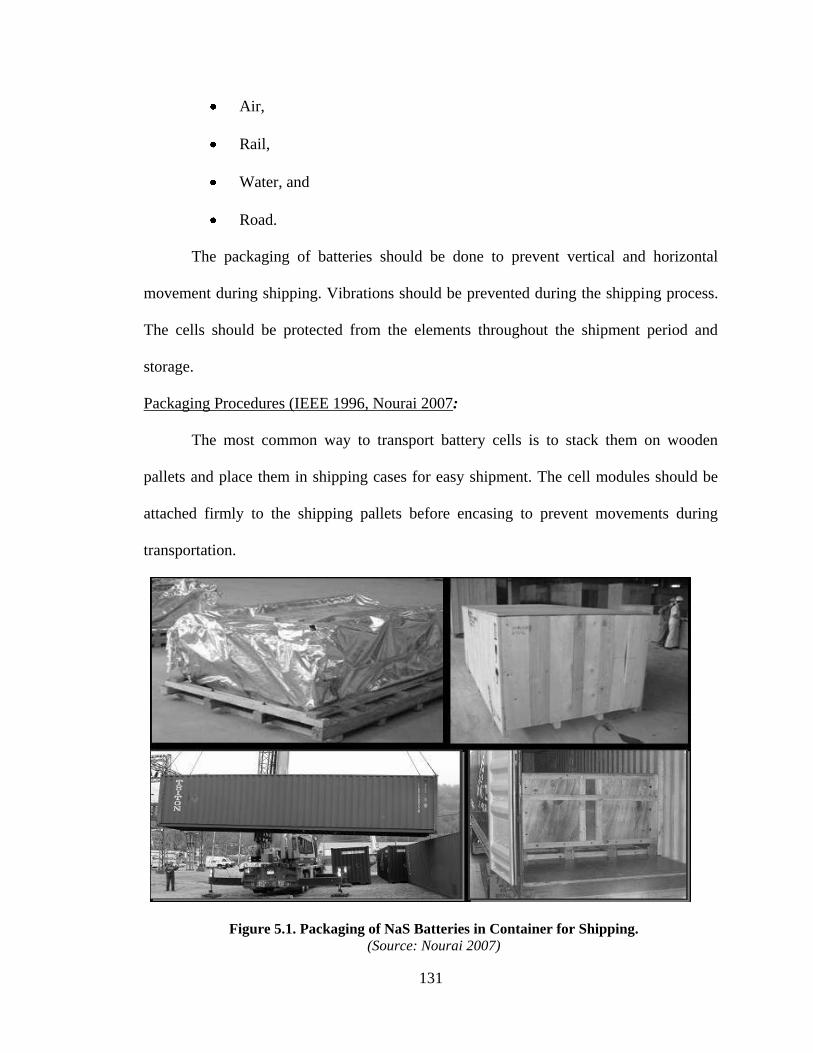
131
Air,
Rail,
Water, and
Road.
The packaging of batteries should be done to prevent vertical and horizontal
movement during shipping. Vibrations should be prevented during the shipping process.
The cells should be protected from the elements throughout the shipment period and
storage.
Packaging Procedures (IEEE 1996, Nourai 2007:
The most common way to transport battery cells is to stack them on wooden
pallets and place them in shipping cases for easy shipment. The cell modules should be
attached firmly to the shipping pallets before encasing to prevent movements during
transportation.
Figure 5.1. Packaging of NaS Batteries in Container for Shipping.
(Source: Nourai 2007)

132
Figure 5.2. Delivery and unloading of Battery Cell Shipping Cases on Site
(Source: Nourai 2007)
Receiving (IEEE 1997)
All cells should be inspected visually after receiving. If damage is apparent, a
more detailed inspection should be done for the entire shipment consignment. Cells with
defects, such as cracked jars or loose terminals, should be returned for repair or
replacement. All received cells should be stored in a dry place away from the elements.
The manufacturer‘s recommendations for storage and handling should be adhered to and
no cells should be stored over the recommended time without charging.
5.2.4. Product Installation
Installation Standards
Existing installation guides are:

133
IEEE Standard 450-1995, IEEE Recommendation Practice for Maintenance,
Testing and Replacement of Vented Lead Batteries for Stationary Applications
(ANSI).
IEEE Standard 484-1996, IEEE Recommended Practice for Sizing Lead Acid
Batteries for Stationary Applications.
IEEE Standard 485-1997, IEEE Recommended Practice for Installation Design
and Installation of Vented Lead Acid Batteries for Stationary Applications.
IEEE Standard 1184-1994, IEEE Guide for Selection and Sizing of Batteries for
Uninterruptible Power Systems (ANSI).
ANSI/NFPA 2011 National Electric Code.
IEEE 1115-1992, IEEE Recommended Practice for Sizing Large Nickel-
Cadmium Batteries for Stationary Applications.
IEEE 1100-2005 Power and Grounding Sensitive Electronic Equipment (ANSI).
IEEE C2 National Electric Safety Code.
Battery Installation
The installation of the cells should follow all manufacturers‘ instructions. All
terminals, posts, and connection hardware should be free from all dirt and corrosion. The
cells should be installed in a sequential order to enable easy identification during
operation and maintenance (IEEE 1997).

134
Figure 5.3. Delivery and Installation of Battery Cell Enclosure on Foundation
(Source: Nourai 2007)
Figure 5.4. Installation of PCS on Foundation Pads
(Source: Nourai 2007)

135
Figure 5.5. Installation of Battery Cells into Cell Enclosures
(Source: Nourai 2007)
There are no specific standards governing the installation of all energy storage
devices. There are, however, some installation guides for the installation of old
technologies sich lead acid storage systems. The IEEE, in recognizing this limitation, has
commissioned a working group (P2030.2) to develop standards for integrating energy
storage devices into smart grids (IEEE SmartGrid 2011).
Power Conversion System
The power conversion system (PCS), which is usually installed with the ESD,
converts AC power to DC to charge the ESD and controls the discharge of stored power
back into the grid. The foundation and installation requirements for PCS are similar to
those for ESD.

136
Figure 5.6. Installation of the Power Conversion System
(Source: Nourai 2007)
5.2.5. Design and Construction of Supporting Components
Foundations
The foundations for transformers can be either precast or cast in place. The
foundation pads should be designed to accept all normal applied and imposed loadings
without damage or settlement. Foundation should be designed to satisfy soil conditions
on site. The pad layout should be done with accurately and must satisfy all utility, local,
and state ordinances. The pad design should be done by a profession engineer. The pad
surface should be slightly sloped to prevent water collection at transformer base. The
foundation can be precast or cast in place.
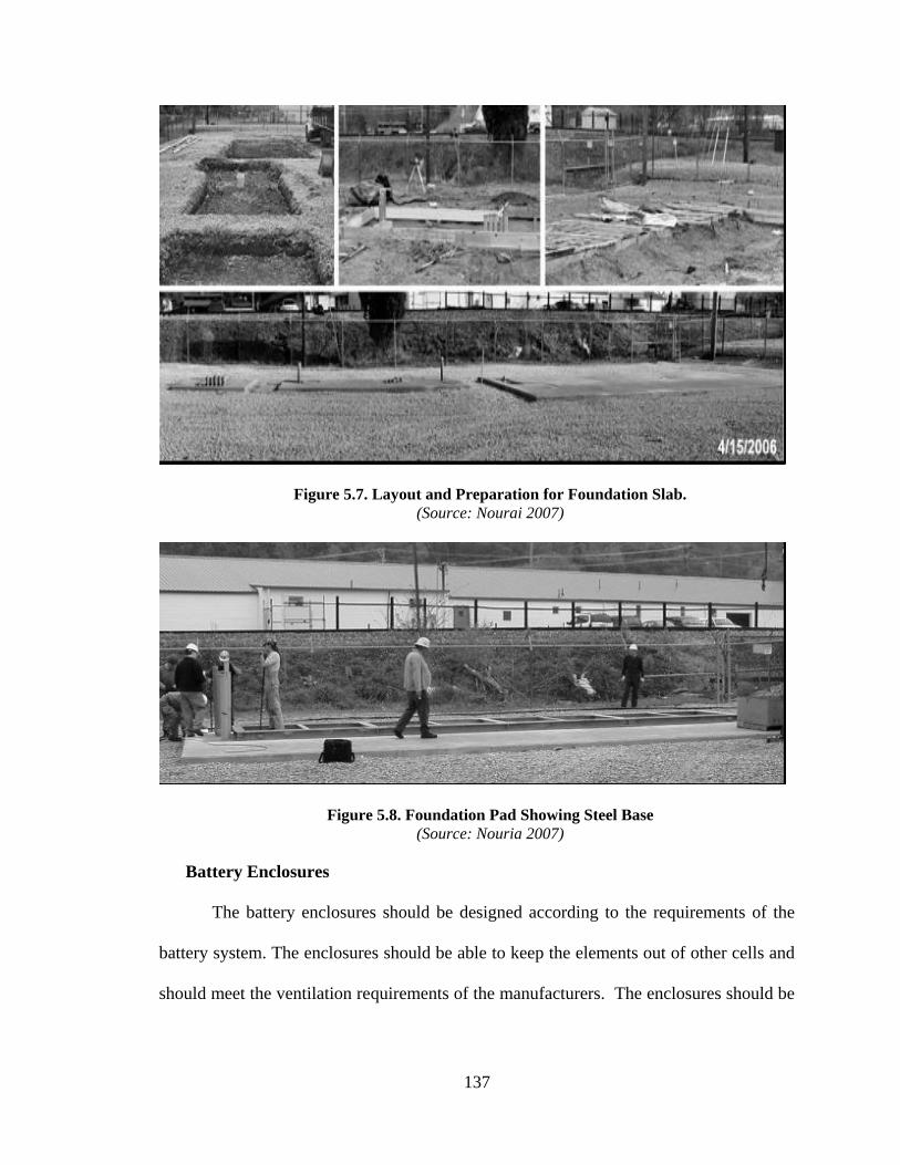
137
Figure 5.7. Layout and Preparation for Foundation Slab.
(Source: Nourai 2007)
Figure 5.8. Foundation Pad Showing Steel Base
(Source: Nouria 2007)
Battery Enclosures
The battery enclosures should be designed according to the requirements of the
battery system. The enclosures should be able to keep the elements out of other cells and
should meet the ventilation requirements of the manufacturers. The enclosures should be

138
sturdy enough to contain the battery cells. The manufacturing and design should be in
accordance with the manufacturers‘ operational requirements for heat and ventilation.
5.2.6. Construction Project Management
Refer to construction management for substation and smart transformers and
Table 5.5.
5.2.7 Electrical Contractors Scope of Work
A work scope was developed for EC for ESD. This work scope was developed
from literature and verified by the ELECTRI-NECA task force. The work scope for ESD
includes:
Procuring and installing energy storage devices,
Installing power conversation systems,
Installing measurement and communication components,
Installing step-up transformers,
Building battery control rooms,
Monitoring connections to distribution monitoring systems (DMS),
Testing and commissioning ESD, and
Providing technical support to owners.

139
Table 5.1a. Checklist for Construction Management and Installations
(Overall Power System Design and Location, Planning, Zoning, and Environmental Considerations)
Construction Management and Installation Energy
Storage Devices
Level of
Importance (EC)
Responsibility of
I. Overall Power System Design
Effect on Overall Power System Design
Power System Design (Gomez et al., 2010)
Will limit the size of generation plants.
Help to meet power demands in peak demand
times.
Help meet power quality demands.
Smoothing out load peaks.
Provide energy as back up during instantaneous
primary energy shut downs.
Enable the widespread deployment of wind and
solar installations as power can be stored during
off-peak periods.
Low
II. Location, Planning , Zoning and Environmental Consideration
Permits and Approvals
Permitting
Environmental enhancement and site
restoration
Safety Plans
Safety manuals and procedures
grounding practices
Daily job hazard assessments
Environmental Plans
Noise Control
Erosion and Sedimentation Control
High
Owner
EC

140
Table 5.1b. Checklist for Construction Management and Installations (Product Procurement)
Construction Management and Installation Energy
Storage Devices
Level of
Importance (EC)
Responsibility of
III. Product Procurement
ESD Procurement
ESD Lead Time
Transportation Requirements for ESD
Delivery
Most common transportation methods
Truck, Railroad, Sea Carrier, and Air Carrier
Lead time for ESD depends on complexity of design, size,
worldwide demand for product, vendor, etc.
Major suppliers:
NaS – NGK Insulators LTD Japan
Flywheels - Beacon , VYCON
Lead Acid Batteries – GNB Power , Delco
Lithium Ion Batteries – SAFT, A123 Systems
Vanadium Redox Batteries- Prudent Energy
Zinc Bromide – ZBB
High
Owner/EC /Product
Vendor
Crane Procurement
Cranes should be able to move batteries without damage.
The operator‘s experience is of a high priority
Normal EC
Access Roads and Transportation on Site
Site Preparation
Erosion Control and Fencing
Grading and Road Improvements
Crane Deployment On Site
Trenching and Cable Laying
EC/Subcontractor
Inspections and Commissioning Performed under NEC requirements High EC/Subcontractor

141
Table 5.1c. Checklist for Construction Management and Installations (Product Installation)
\
Construction Management and Installation Energy Storage
Devices
Level of
Importance (EC)
Responsibility of
1 2 4 5
IV. Product Installation
Installer /Technician Qualifications ANSI /NETA ETT 2000
Installation Code and Standards IEEE Standard 450-1995, IEEE Recommendation Practice
for Maintenance, Testing and Replacement of Vented Lead
Batteries for Stationary Applications (ANSI)
IEEE Standard 484-1996, IEEE Recommended Practice
for Sizing Lead Acid Batteries for Stationary Applications
IEEE Standard 485-1997, IEEE Recommended Practice
for Installation Design and Installation of Vented Lead Acid
Batteries for Stationary Applications
IEEE Standard 1184–1994, IEEE Guide for Selection and
Sizing of Batteries for Uninterruptible Power Systems (ANSI)
ANSI/NFPA 2011 National Electric Code
IEEE 1115–1992, IEEE Recommended Practice for Sizing
Large Nickel-Cadmium Batteries for Stationary Applications
IEEE 1100–,2005 Power and Grounding Sensitive
Electronic Equipment (ANSI)
IEEE C2 National Electric Safety Code
EC
Requirements on Site
Site Preparation
Erosion Control and Fencing
Grading and Road Improvement
Normal EC/Subcontractor
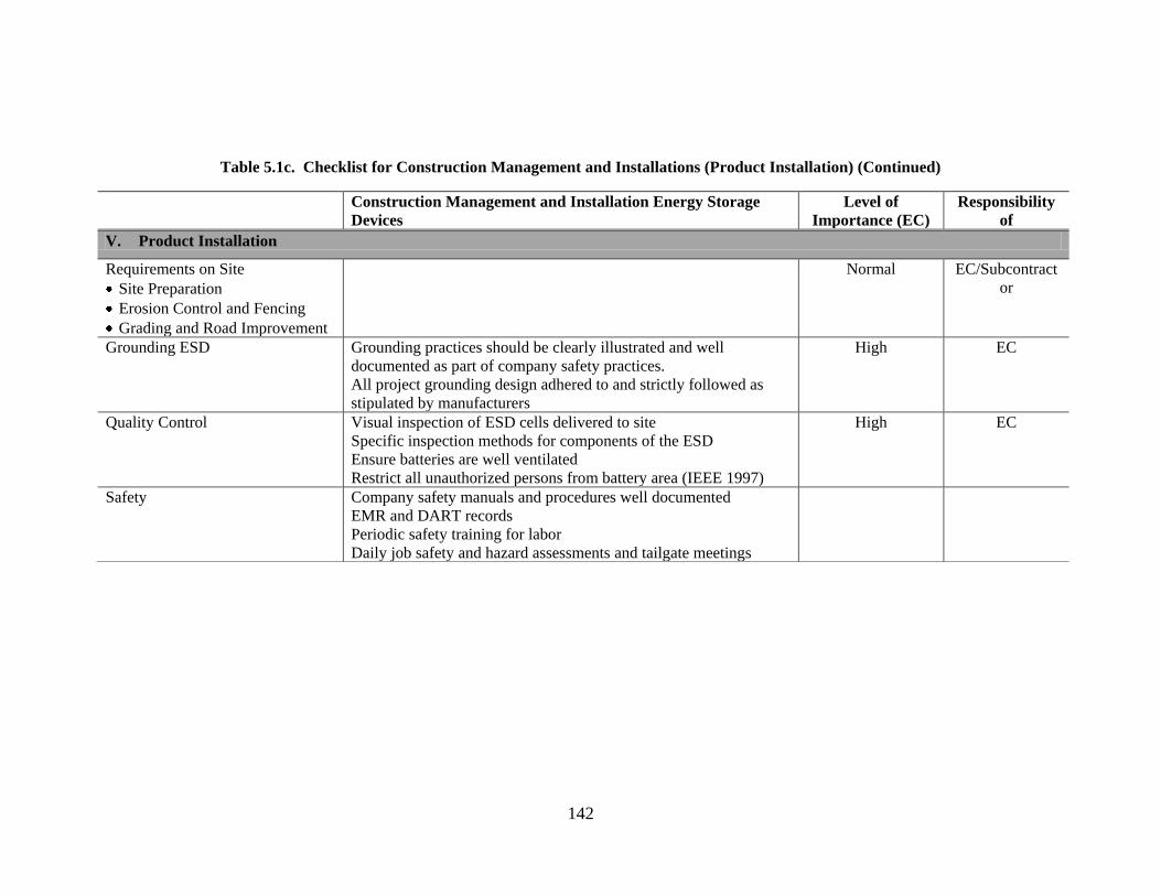
142
Table 5.1c. Checklist for Construction Management and Installations (Product Installation) (Continued)
Construction Management and Installation Energy Storage
Devices
Level of
Importance (EC)
Responsibility
of
V. Product Installation
Requirements on Site
Site Preparation
Erosion Control and Fencing
Grading and Road Improvement
Normal EC/Subcontract
or
Grounding ESD Grounding practices should be clearly illustrated and well
documented as part of company safety practices.
All project grounding design adhered to and strictly followed as
stipulated by manufacturers
High EC
Quality Control Visual inspection of ESD cells delivered to site
Specific inspection methods for components of the ESD
Ensure batteries are well ventilated
Restrict all unauthorized persons from battery area (IEEE 1997)
High EC
Safety Company safety manuals and procedures well documented
EMR and DART records
Periodic safety training for labor
Daily job safety and hazard assessments and tailgate meetings

143
Table 5.1d. Checklist for Construction Management and Installations
(Design and Construction of Supporting Components and Construction Project Management)
Construction Management and Installation Energy Storage Devices Level of
Importance (EC)
Responsibility of
VI. Design and Construction of Supporting Components
Foundations
Battery Enclosures
Foundation pad layout should satisfy local and state ordinances
Anchor bolts should be accurately aligned
Steel bases for the foundation should be well aligned to receive battery
enclosures
Battery enclosures and racks should be embedded using approved
fastening techniques
When batteries are installed in the building, caution should be taken in
anchoring the enclosures to the walls and the floor as this might cause
stress from vibration (IEEE 1997)
High EC CM
Subcontractor
Anchor Materials Size length must meet ASTM A 36 (ASCE 2008) High EC
VII. Construction Project Management
Project Team Qualifications
and Availability
Team members and qualifications should be clearly stated and presented
to owner
High EC
Project Estimate
Attention given to complexity of installation, contract requirements,
project duration, commodity price escalation, and market conditions.
High EC
Project Schedule Provide milestone, phase, monthly, and daily look-ahead schedules High EC
Project Controls
Bar Charts
S Curves
Earn Value Analysis
High EC
Quality Assurance Plans Warranty for work performed encouraged
Warranty on all equipment documented
High EC
Safety Company safety manuals and procedures well documented
EMR and DART records
Periodic safety training for labor
Daily job safety and hazard assessments and tailgate meetings

144
Table 5.2. Work Scope of Electrical Contractors for Energy Storage Devices
Work scope of Electrical Contractors for Energy Storage Devices
Self-Performed Subcontractors
Consultant
Procuring and Installing Energy Storage
Devices
Installation of Power Conversion Systems
Installing Measurements and
Communication Components
Installation of Step-Up Transformers
Battery Control Rooms
Connection to Distribution Monitoring
Systems (DMS)
Testing and Commissioning ESD
Consulting and Training
Project Management
Development of Specifications
Siteworks
Excavating and Backfilling
Stripping and Clearing
Grading
Drainage
Fencing
Access Roads
Communication Systems Installations
Erosion and Sedimentation Control
Concreteworks
Foundations
Environmental Planning
Land Reclamation
Erosion and Sedimentation Control
Consultants
Environmental
Design
Communication Systems and
Information Technology
Workforce Training
Surveying and Right-of-Way
Engineering
Community Education Plans

145
5.3. ADVANCED SUPERCONDUCTING TRANSMISSION CABLES
The introduction of HTS conductors to the market is one of the major changes in
the electricity transmission and distribution industry. HTS conductors have not yet gained
mainstream acceptance due to their limited availability, high cost, and the lack of
installation experience among line workers.
5.3.1. Overall Power System Design
The introduction of advanced superconducting transmission cables will
revolutionarize the way power systems are designed. A power system is designed with
transmission losses as the primary design factor. The introduction of superconducting
cables changes this design paradigm. This is because, in some super-conducting cables,
transmission losses approach zero or are almost negligible. As such, the primary design
factor might shift to other areas of consideration such as economic constraints, aesthetics,
environmental effects, and the like. (Case Study 16, 2011).
5.3.2. Location, Planning, Zoning, and Environmental Considerations
Transmission lines affect the environment in several ways, be it the right-of-way
clearance through forests and agricultural lands or erosion problems from construction
activities. According to PSC of Wisconsin (2010), the effects of transmission lines on the
environment can impact a variety of areas:
Aesthetics,
Agricultural lands,

146
Airports and airstrips,
Archeological and historical sites,
Electric/magnetic fields,
Endangered species,
Noise,
Property owner impacts,
Radio and television reception,
Recreation areas,
Safety,
Stray voltage,
Waterways,
Wetlands, and
Woodlands.
During construction, mitigating procedures and processes need to be employed to
reduce environmental effects. Siting difficulty has been one of the main reasons why
transmission lines have not been built to keep up with demand in the past few years
(Casper & Wellstone, 1981; Pierobon, 1995; Abel 2005; Vajjhala & Fischbeck, 2006).
Although the United States has the largest and one of the most reliable electricity systems
in the world, electricity transmission and distribution expansion has not matched growing
demand (CECA/RF, 1990; DOE, 2002; EEI, 2002; Hirst and Kirby, 2001). Many
Americans would like to see the adaptation of renewable energy solutions; however,
there is still a lot of community resistance when such facilities are sited.

147
Renewable energy projects have, at times, provoked more opposition than one
might have thought, mostly due to its being located in isolated and pristine places near
mountains, coastal water, or plains.
The most commonly identified problems with siting renewable energy or
transmission lines fall into these obstacles to the process of finding locations for new
facilities include public opposition; environmental, topographic, and geographic
constraints; interagency coordination problems; and local state and federal constraints
(Gale & O‘Driscoll 2001; Vajjhala 2006; Vajjhala & Fischbeck 2006).
Transmission Permitting Process
Figure 5.9. Right of Way
(Source: ATC 2011)
RIGHT-OF-WAY
(Easement area)

148
The permitting and siting of transmission lines is usually seen as a major
impediment to transmission development in the United States. There have been several
attempts to rectify and streamline the permitting process and the requirements needed for
transmission installations. Aside from the delays caused by the transmission siting
process, transmission costs make up about 10% of the average electric bill (DOE 2002).
In the EPACT (2005), the Federal Energy Regulatory Commission (FERC) was
authorized to consider a transmission siting application if the permitting state had not
worked on the transmission application in a year or failed to recognize the interstate
benefits of the project (FERC 2011). Also, the EPACT 2005 allowed three or more
contiguous states to form interstate pacts to facilitate transmission line siting within the
states. These laws were passed to encourage the speedy processing of transmission
projects through state agencies. However, this has not been the case (Case Study 15,
2011).
The voltage of the transmission line determines the width of the right-of-way. The
right-of-way is usually about 100–200 feet wide and must conform to all vegetation
management standards (FERC 2011). In the state of Michigan, the Michigan Public
Services Commission (MPSC) has oversight over the siting of transmission lines in the
state. This authority is governed under the Michigan Electric Transmission Line
Certification Act (Davies et al., 2010). The utility companies have to present an
application to the MPSC within five years of commencing planning for a major
transmission line. The application must contain a description of the project, the
transmission route, and an evaluation of alternative routes. A public hearing will be heard
before a certificate is issued for construction to proceed (Davies et al., 2010).
149
An expedited certificate can be issued for transmission lines for the transportation of
electricity generated from wind energy as a result of Michigan Public Act 295 (2008).
5.3.3. Product Procurement
The company contacted during the case study was not installing HTS conductors on
their main transmission lines. This is due to problems the company had with the new
technology. These problems included longer lead times and the unavailability of
conductors on the market; hence, it was not a good fit in times of emergency repairs,
which is a major factor in determining the products used. They were also not conversant
on the topics of the installation equipment and processes needed for HTS installations
Contract Delivery Systems
Transmission and utility companies use several delivery systems to procure
transmission and distribution contracts. Transmission contracts can either be a guaranteed
maximum price (GMP), or time, and material arrangement, where the owner provides all
materials and the contractor is paid for installation time, or a traditional competitive bid.
The delivery system will be determined on the owner and his experience procuring
projects (Case Study 5, 6, and 14, 2011).
5.3.4. Product Installation
Installation Standards
Transmission conductors are installed following IEEE Standard 524-2003 (IEEE
2004).

150
Installer / Technician Qualifications
There are no nationally recognized smart grid technician certifications. Smart grid
technology requires a spectrum of skilled trade certifications for traditional line men and
substation installers. The substation wiremen should have at least completed a substation
wireman apprenticeship or equivalent training, or should be graduates of electric
technician programs from community colleges and technical schools that prepare students
for current entry-level work as substation technicians. One existing certifications for
traditional linemen is the American National Standards Institute and International Electric
Training Association (ANSI/NETA ETT) certification.
Foundation Types
The choice of foundation is usually determined by a structural engineer. The
foundation type is dependent on the loading and type of support members used. The most
common types of foundations used for pole and lattice construction are:
Gravity foundations using reinforced concrete slabs,
Pile foundations with concrete slabs, and
Sheet pile foundations with concrete slabs.
The case study transmission company contacted during this study was skeptical of
the installation processes and equipment needed for HTS cables. The installation
processes illustrated in this section are adopted from the 3M Corporation‘s handbook on
ACCR installation and maintenance.
Installation Equipment (3M 2011)
Drum pullers are used in the stringing procedures of ACCR conductors. This is
done in conjunction with a back-tensioning device such as a bullwheel tensioner.

151
According to the 3M Corporation, this device can be used with any installation of ACCR
conductors.
Figure 5.10. Drum Pullers for Stringing ACC Conductors
(Source: 3M 2011)
Bullwheel Tensioners
Bullwheel tensioners have been used for the installation of ACCR conductors.
The manufacturer recommends the use of a larger-sized bullwheel diameter when
stringing this type of conductor.
Figure 5.11. Bullwheel Tensioners
(Source: 3M 2010)
Stringing Blocks
A combination of high-stringing tension with a small bend radius can damage the
inner core wires of the composite conductor. Larger diameter stringing blocks are

152
required when installing ACCR. A roller array block is required at all break-over towers
and high running angles
Figure 5.12. Stringing Block
(Source: 3M 2010)
Socket Splice
A socket splice, also known as a basket grip or Kellem grip, can be used to string
ACCR conductors. The double swivel connection is recommended for use with the
socket splice to reduce any twisting of the conductor during the tension stringing
operation. The conductor should not be used if it is under the socket splice. Bands should
not be used on the end to hold the socket splice, as this can cause damage to the
composite cores in the conductor. Friction tape should be applied over the end of the
socket splice and the conductor. Figure 5.20 shows a typical socket splice in use.
Figure 5.13. Socket Splice
(Source: 3M 2011)

153
Cable Cutters
Cable cutters are used to cut ACSR or AAAC conductors in order to prevent the
conductor strand from unstranding.
Conductor Grounding Clamps
Grounding clamps that are used on traditional conductors are compatible with the
ACCR conductor. Grounding clamps should be sized appropriately to fit the conductor
being installed.
Figure 5.14. Conductor Grounding Clamp
(Source: 3M 2011)
Running Grounds
Running grounds or traveling grounds can be used when installing ACCR
conductors. A properly sized running ground should be used when installing the ACCR
conductor.

154
Figure 5.15. Running Ground
(Source: 3M 2010)
Reel Stands
Standard reel stands may be adopted to hold the reels of ACCR conductors during
the stringing operation. Reel stands, combined with bullwheel tensioners can be been
used to ensure proper back tensions on the ACCR conductor. It is recommended by
manufacturers that a bullwheel tensioner along with a reel stand be used to maintain
proper stringing tensions.
Chicago Grips
The use of Chicago grips is prohibited on ACCR cables.
Insulator and Hardware Assemblies
Cable Stringing
There are four main methods of stringing overhead transmission conductors
(Caulkins, 1987):
1. Slack stringing,
2. Semi tension,
3. Full Tension, and
4. Helicopter.

155
In the installation of composite cables, this research focused on tension stringing
as there was little to no information on the other stringing methods. According to the 3M
Corporation (2011), similar installation equipment used for traditional steel cables can be
used in the installation of ACCR cables.
Tension Stringing
The stringing procedure recommended for use when installing ACCR conductors
is the tension stinging method. This involves pulling the ACCR conductor under tension.
The cable should not be allowed to drag on the ground. The ―slack‖ stringing procedure
is not recommended for ACCR cables. This involves the pulling of the conductor out on
the ground by means of a pulling truck or placing it out on the ground by dispensing the
cable from a moving vehicle holding the reel stand.
According to manufacturers, it is important to maintain sufficient back tension
when installing the ACCR conductor so as not to allow the conductor to drag onto the
ground or any support structures that might be used. Nevertheless, too much back tension
combined with small bend radii such as small diameter stringing blocks can cause
damage and destruction to the inner composite core wires.
Major equipment required for tension stringing includes reel stands, tensioners,
drum pulleres, large stringing blocks, socket splices, and conductor grips such as DG
grips or preformed dead ends.
Sagging Procedures
Methods of sagging that have been used on the ACCR include line-of-sight
measurements and rope or wave reflection sagging. Sagging procedures for ACCR
conductors are very similar to that of any other conductor. Whether or not a compression
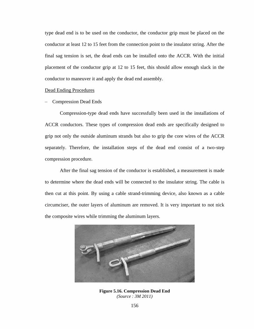
156
type dead end is to be used on the conductor, the conductor grip must be placed on the
conductor at least 12 to 15 feet from the connection point to the insulator string. After the
final sag tension is set, the dead ends can be installed onto the ACCR. With the initial
placement of the conductor grip at 12 to 15 feet, this should allow enough slack in the
conductor to maneuver it and apply the dead end assembly.
Dead Ending Procedures
– Compression Dead Ends
Compression-type dead ends have successfully been used in the installations of
ACCR conductors. These types of compression dead ends are specifically designed to
grip not only the outside aluminum strands but also to grip the core wires of the ACCR
separately. Therefore, the installation steps of the dead end consist of a two-step
compression procedure.
After the final sag tension of the conductor is established, a measurement is made
to determine where the dead ends will be connected to the insulator string. The cable is
then cut at this point. By using a cable strand-trimming device, also known as a cable
circumciser, the outer layers of aluminum are removed. It is very important to not nick
the composite wires while trimming the aluminum layers.
Figure 5.16. Compression Dead End
(Source : 3M 2011)

157
– Compression Splices
Compression-type conductor splices have successfully been used in the
installations of ACCR conductors. These types of compression splices are specifically
designed to grip not only the outside aluminum strands but also to grip the core wires of
the ACCR separately. Therefore, like the compression-type dead end assembly, the
installation steps of the full tension splice consist of a two-step compression procedure.
It is recommended that the minimum distance from a splice location to a dead end or
suspension tower should be 50 feet (15M). The two ends of the conductor that are going
to be spliced are brought together and held by the use of a chain hoist and two conductor
grips. Conductor grips must be spaced out so that the installation of the splice does not
interfere with the conductor grips themselves.
Figure 5.17. Full Tension Compression Splice
(Source : 3M 2011)
Miscellaneous Components
T-Tap Connectors

158
T-Tap connectors have been used in the installation of ACCR conductors. These
types of connectors can be installed directly over the outside layer of the ACCR. These
types of connectors usually have a breakaway torque bolt that automatically sets the
needed torque specification of the hardware.
Figure 5.18. Pad Tap Connector
(Source : 3M 2011)
Vibration Dampers
Vibration dampers have been successfully used in the installations of ACCR
conductors. Typical vibration dampers have a breakaway torque bolt that ensures the
proper torque setting when installed on the conductor. Tests have shown that the clamps
used with the vibration dampers do not cause any damage to the composite core wires of
the ACCR.
Figure 5.19. Vibration Dampeners
(Source : 3M 2011)
Bundle Spacers

159
Spacers are qualified for use on ACCR conductors on bundled installations. The
two spacer halves are connected together at the proper location of the bundle conductor
for each span. The two halves are connected using a single breakaway bolt to ensure that
the two halves are connected and tightened to the correct torque. The final step of the
spacer installation involves applying a single layer of protector rods over the conductor
and centered over each side of the connection point of the spacer to on the conductor.
Figure 5.20. Bundle Spacer Installation
(Source : 3M 2011)
5.3.5. Design and Construction of Supporting Components
Types of Transmission Towers
Transmission towers come in several types depending on the structural loads to be
carried, land layout, distances to be spanned, local regulations, and the like (FERC 2011).
The most commonly used types of transmission towers are shown in the figures on the
next page.

160
Figure 5.21. Double Circuit 138kv on Wood
(Source ATC 2011)
Figure 5.22. Double Circuit 138kv on Galvanized Steel
(Source: ATC 2011)

161
Figure 5.23. 38-Kilovolt Single-Circuit Line on Weathering Steel
(Source: ATC 2011)
Figure 5.24. H-Frame Wood Structure
(Source: ATC 2011)

162
Figure 5.25. Double-Circuit 138-Kilovolt Line On Steel Lattice Tower
(Source: ATC 2011)
Figure 5.26. 138-Kilovolt Steel H-Frame
(Source: ATC 2011)
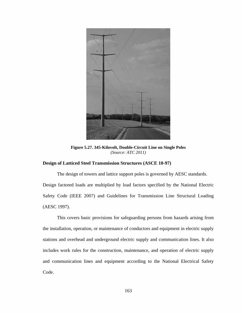
163
Figure 5.27. 345-Kilovolt, Double-Circuit Line on Single Poles
(Source: ATC 2011)
Design of Latticed Steel Transmission Structures (ASCE 10-97)
The design of towers and lattice support poles is governed by AESC standards.
Design factored loads are multiplied by load factors specified by the National Electric
Safety Code (IEEE 2007) and Guidelines for Transmission Line Structural Loading
(AESC 1997).
This covers basic provisions for safeguarding persons from hazards arising from
the installation, operation, or maintenance of conductors and equipment in electric supply
stations and overhead and underground electric supply and communication lines. It also
includes work rules for the construction, maintenance, and operation of electric supply
and communication lines and equipment according to the National Electrical Safety
Code.

164
Minimum Sizes
A minimum thickness of 1/8th
inch for members and 3/16th
inch for connection
plates is suggested.
Tolerances Established By Suppliers
Tolerances contained in ASTM Specification A6 should be used as a guide
The commonly used fasteners for lattice transmission towers are ASTM A394 for bolts
and A563 for nuts.
Welding
Welding procedures shall comply with ANSI / AWS D1.1.
Direct Embedded Structures
Structures designed for direct embedment is recommended to be tested in a two
part program:
1. Soil properties.
2. Above-ground portion– tests on anchors and components.
Concrete foundations should be properly sloped to drain so that water pockets do
not accumulate with ground material and cause excessive corrosion of the tower‘s base
material.
If steel is exposed to groundwater, special protection is essential. Proper drainage
around the steel should be established and periodic inspections conducted. If any steel
members are located in severe ground conditions, the thickness will have to be increased
by at least 1/16 inches for corrosion allowance.
165
Design of Steel Structures (AESC/SEI 48-05)
Factored Design Loads
Minimum legislated loads are specified according to codes covered by states and
local authorities and must meet National Electric Safety Code (NESC). Individual utility
companies‘ planning criteria will usually dictate specific conductor and shield wire sizes.
Historical local climates may dictate loads in excess of legislated loads include ice and
winds and their combination at specified temperatures. Planning criteria may require
measures to prevent cascading failure.
Utility companies need to consider unique loading situations that are applicable to
their service area. Tubular frame structure design may need to account for the effects of
foundation movement caused by earth movement.
Design Restrictions
Shipping length and weight restrictions are influenced by construction site
conditions and material handling limitations. Structure diameter, taper, and deflection
restrictions are influenced by the desired appearance of the installed structure. Hot dip
galvanized, weathering, painting, and zinc silicate coating are the most commonly used
finishes and all influence the exposure, appearance, and regulatory requirements.
Connections and Fasteners
Fasteners are designed as sheer, slip-critical, or sheer-type connections. Typical
anchor bolt holes in base plates are 0.375–0.5 inch. Tolerances contained in ASTM
Specification A6 should be used as a guide. Commonly used fasteners for pole
transmission towers are ASTM A325, A354 A394, A449, and A490 for bolts and A563
for nuts.

166
Welded Connections
Slip Joints
An overlap of 1.42–1.52 times the maximum diameter of the outer section is
sufficient to develop the required strength.
Detailing and Fabrication
A tower detail drawing consists of erection drawings and bills of materials.
Erection drawings show the complete assembly of the structure indicating clearly the
position of the members. The owner should coordinate the dimensioning of mating parts
obtained from different sources.
Cutting
Any curve or straight edge can be cut with a burning torch. Care must be taken to
prevent cracks or other notch defects from forming. Edges prepared for welding should
be free from sharp notches. Edges cut with a handheld torch will require grinding to
remove notches.
Welding
Welding procedures shall comply with ANSI / AWS D1.1. Workmanship is
important for pole structures.
Holes
Holes may be punched or drilled. Care must be taken to maintain accuracy.
Identification
The marks on pieces should be at least 0.50 inches in height.

167
Anchor Bolts
The size and length of anchor bolts should be determined by a structural engineer
with consideration of the dead and live loads on the transmission line. Threaded
reinforced bards are the most common type of anchor bolt and must meet ASTM A615
grade 60 for #5–#18 bars and grade 75 for #11–#18 bars.
5.3.6. Construction Project Management
Scheduling
The use of loaded CPM schedules should be used to present milestone schedules.
There should be several schedules for production management. The detail of each
schedule should be determined by the level of utilization. Milestone and phase Critical
Path Method (CPM) schedules should be prepared for the use of upper-level management
and project managers; weekly look-ahead schedules and bar charts should be used by site
supervisors.
Estimating
Estimates should be combined with the schedule as the basis for the cost planning
and control of the project. Conceptual estimates can be used to predict the final cost for
designing and building projects. On traditional projects, preliminary phase and detailed
schedules should be prepared.
Project Controls
Every project will deviate from its baseline schedule, so the need for a good
project controls systems is imperative if the project is to be completed on time and under
cost. Project controls are the continuous process of (Mubarak, 2004):
168
1. Monitoring the progress of work,
2. Comparing the target schedule and cost with the work in progress,
3. Determining any deviations and analyzing for causes, and
4. Making recommendations and taking corrective actions to bring the project back
on schedule.
The project controls systems will need to use the information and resources of the
estimates and schedule to be able to track the project cost and time. The measurement of
work progressed can be determined through various means, such as work-in-place or
cost-to-date.
Project controls can evaluate project performance by the use of the following:
Bar Charts,
S-Curves (Schedule and Cost ),
Earn Value Management Systems (EVMS),
Safety
The safety record and planning abilities of an EC are two of the most important
criteria for selecting preferred contractors in the transmission industry. This is
particularly important when using new technology with which a contractor‘s employees
may not have the necessary experience in the process and techniques required for
installation. The contractor should be able to prove, with written documentation, a clear
and concise safety plan for his on-field activities. There should be a well-kept safety
record verifiable over a long period of operation. There should be dedicated safety
personnel on site whose roles include, among others:

169
Keeping safety manuals and procedures
Keeping safety records (EMR, DART etc.)
Staying aware of training requirements of labor,
Supervising daily job safety and hazard assessments and tailgate meetings, and
Instituting safety bonuses for field workers when safety targets are achieved.
Safety of Maintenance Personnel (AESC 1997)
The transmission tower must be able to support a vertical load of at least 250 lbs
applied independently to all loads without permanent distortion. In most structures,
horizontal bracing is required to distribute shear and torsional forces. For structures taller
than 200 feet or heavy0end towers horizontal bracing be installed not exceeding 75 feet.
Horizontal bracing is dictated by general stiffness requirements to maintain tower
geometry. Factors affecting the type of bracing are the bracing system, face slope, dead
load sag of face members, and erection considerations that affect member lengths.
Quality Assurance and Quality Control (AESC 1997)
There must be a clear and concise contract between the purchaser and supplier
defining the roles and responsibilities of both parties in the purchase, design, detail,
testing, fabrication. and delivery of transmission materials.
The purchaser‘s QA program outlines the methods, types of inspections, and
records necessary to provide production controls.
The QA program defines the personnel that have the responsibility for contract
performance, engineering, inspection, and receipt of materials. Contract performance
covers enforcement of the terms of the contract relative to payments, delivery
commitments, contract changes, and legal matters.
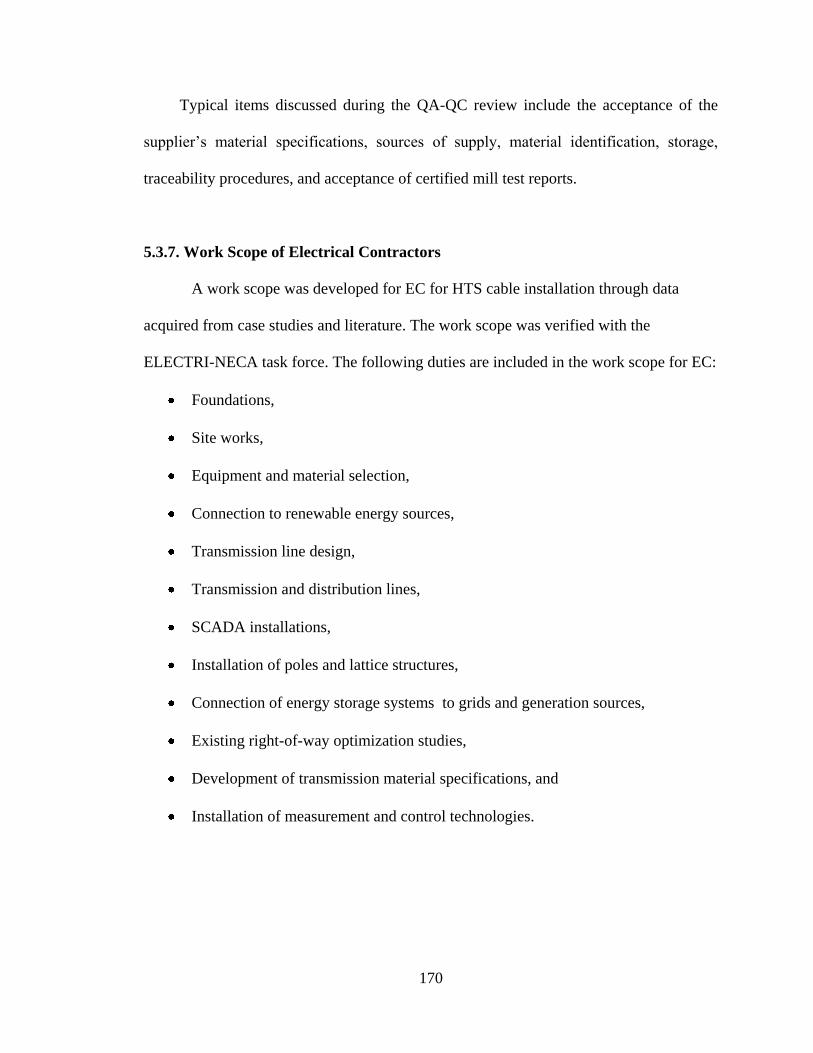
170
Typical items discussed during the QA-QC review include the acceptance of the
supplier‘s material specifications, sources of supply, material identification, storage,
traceability procedures, and acceptance of certified mill test reports.
5.3.7. Work Scope of Electrical Contractors
A work scope was developed for EC for HTS cable installation through data
acquired from case studies and literature. The work scope was verified with the
ELECTRI-NECA task force. The following duties are included in the work scope for EC:
Foundations,
Site works,
Equipment and material selection,
Connection to renewable energy sources,
Transmission line design,
Transmission and distribution lines,
SCADA installations,
Installation of poles and lattice structures,
Connection of energy storage systems to grids and generation sources,
Existing right-of-way optimization studies,
Development of transmission material specifications, and
Installation of measurement and control technologies.
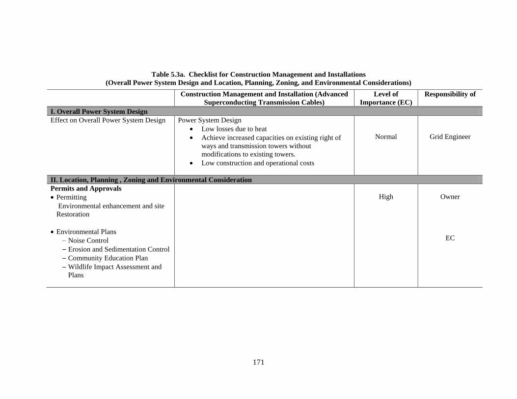
171
Table 5.3a. Checklist for Construction Management and Installations
(Overall Power System Design and Location, Planning, Zoning, and Environmental Considerations)
Construction Management and Installation (Advanced
Superconducting Transmission Cables)
Level of
Importance (EC)
Responsibility of
6. I. Overall Power System Design
Effect on Overall Power System Design Power System Design
Low losses due to heat
Achieve increased capacities on existing right of
ways and transmission towers without
modifications to existing towers.
Low construction and operational costs
Normal
Grid Engineer
7. II. Location, Planning , Zoning and Environmental Consideration
Permits and Approvals
Permitting
Environmental enhancement and site
Restoration
Environmental Plans
Noise Control
Erosion and Sedimentation Control
Community Education Plan
Wildlife Impact Assessment and
Plans
High
Owner
EC

172
Table 5.3b. Checklist for Construction Management and Installations (Product Procurement)
Construction Management and Installation (Advanced
Superconducting Transmission Cables)
Level of
Importance (EC)
Responsibility of
8. III. Product Procurement
Advanced Superconducting Transmission
Cables Manufacturers
ACCC
ACCR
HTS
Composite Technology Corporation
3M Corporation
High Owner/EC /Product
Vendor
Access Roads and Transportation on Site
Site Preparation
Erosion Control and Fencing
Grading and Road Improvements
Crane Deployment On Site
Trenching and Cable Laying
EC/Subcontractor
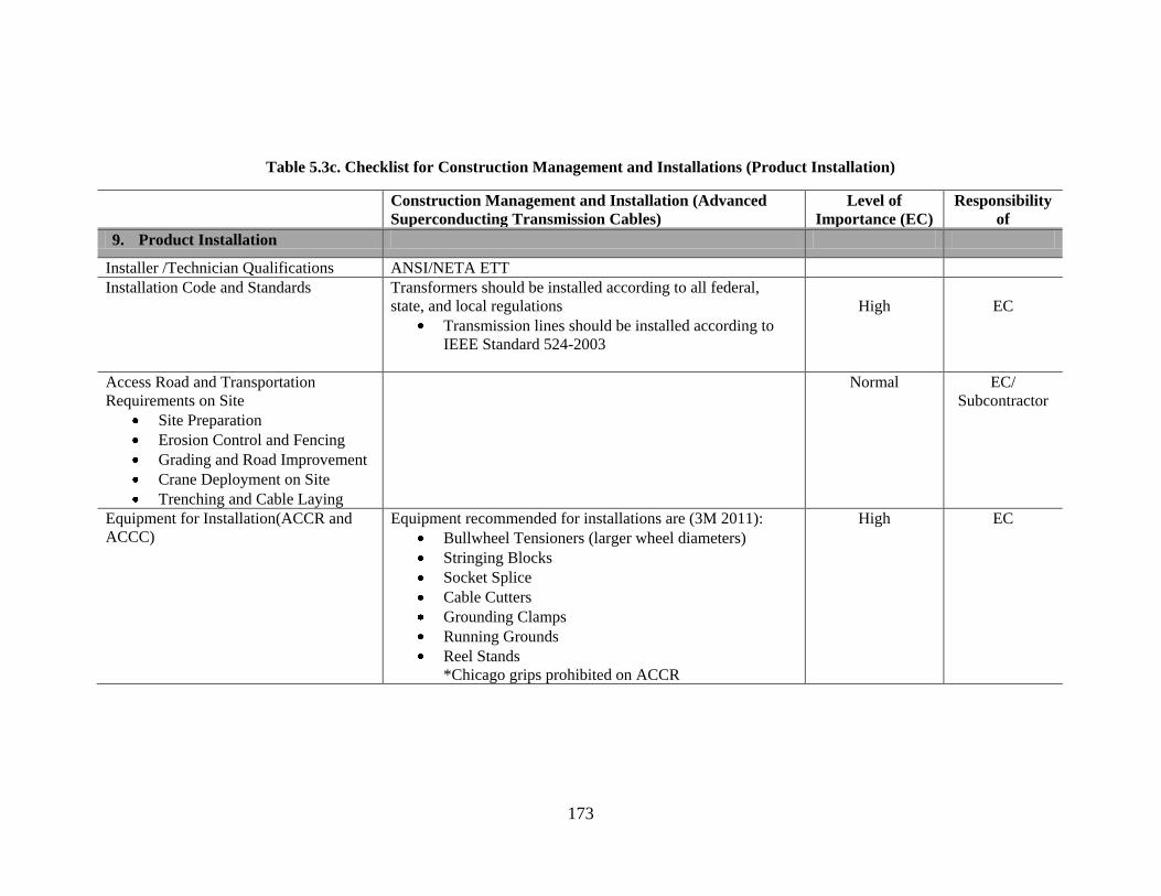
173
Table 5.3c. Checklist for Construction Management and Installations (Product Installation)
Construction Management and Installation (Advanced
Superconducting Transmission Cables)
Level of
Importance (EC)
Responsibility
of
9. Product Installation
Installer /Technician Qualifications ANSI/NETA ETT
Installation Code and Standards Transformers should be installed according to all federal,
state, and local regulations
Transmission lines should be installed according to
IEEE Standard 524-2003
High
EC
Access Road and Transportation
Requirements on Site
Site Preparation
Erosion Control and Fencing
Grading and Road Improvement
Crane Deployment on Site
Trenching and Cable Laying
Normal EC/
Subcontractor
Equipment for Installation(ACCR and
ACCC)
Equipment recommended for installations are (3M 2011):
Bullwheel Tensioners (larger wheel diameters)
Stringing Blocks
Socket Splice
Cable Cutters
Grounding Clamps
Running Grounds
Reel Stands
*Chicago grips prohibited on ACCR
High EC

174
Table 5.3c. Checklist for Construction Management and Installations (Product Installation) (Continued)
Construction Management and Installation (Advanced
Superconducting Transmission Cables)
Level of
Importance (EC)
Responsibility
of
Stringing Procedures
Traditional stringing methods are adopted for HTS cables
depending on design and site conditions.
Slack Stringing
Semi Tension
Full Tension
Helicopter
3M recommends the use of slack tension stringing for
ACCR conductors
High
EC
Sagging Procedures
Sagging procedures adopted for ACCR include (3M, 2011):
Line-of-sight measurements
Wave reflection
High
EC
Safety Company safety manuals and procedures well documented
EMR and DART records
Periodic safety training for labor
Daily job safety and hazard assessments and tailgate
meetings
175
Table 5.3d. Checklist for Construction Management and Installation
(Design and Construction of Supporting Components and Construction Project Management)
Construction Management and Installation (Advanced
Superconducting Transmission Cables)
Level of
Importance (EC)
Responsibility
of
10. V. Design and Construction of Supporting Components
Foundations
Foundation pad layout should satisfy local and state
ordinances
Anchor bolts should be accurately aligned
High EC CM
Subcontractor
Anchor Materials Size length must meet ASTM A 36 (ASCE 2008)
High EC
VI . Construction Project Management
Project Team Qualifications and
Availability
Team members and qualifications should be clearly state and
presented to owner
High EC
Project Estimate
Attention given to complexity in installation, contract
requirements, project duration, commodity price escalation,
and market conditions.
High EC
Project Schedule
Provide milestone, phase, monthly, and daily look-ahead
schedules
High EC
Project Controls
Bar Charts
S Curves
Earn Value Analysis
High EC
Quality Assurance Plans Warranty for work performed encouraged
Warranty on all equipment documented
High EC
Safety Company safety manuals and procedures well documented
EMR and DART records
Periodic safety training for labor
Daily job safety and hazard assessments and tailgate meetings

176
Table 5.4. Work Scope of Electrical Contractors for HTS Transmission Cables
Work scope of Electrical Contractors for HTS Transmission Cables
Self-Performed
Subcontractors Consultant
Specialized Equipment Delivery and
Installation
Circuit Breakers
Line Tracker Communication Meter
Phasor Measurement Units
Wide Area Monitoring Systems
(WAMS)
SCADA systems
Distribution Monitoring Systems
(DMS)
Connection of energy storage
systems to grids and generation
sources
Existing right-of-way optimization
studies
Development of transmission
material specifications
Installation of measurement and
control technologies.
Siteworks
Excavating and Backfilling
Land Reclamation
Stripping and Clearing
Grading
Excavation
Drainage
Dewatering
Fencing
Access Roads
Communication Systems Installations
Erosion and Sedimentation Control
Concreteworks
Foundations
Piers
Culverts
Environmental Planning
Land Reclamation
Erosion and Sedimentation Control
Spill Prevention Control and Countermeasure
Plans
Community Education Plan
Surveying and Right-of-Way Engineering
Consultants
Environmental
Design
Communication Systems and
Information Technology
Workforce Training
Surveying and Right-of-Way
Engineering
Community Education Plans

177
5.4. SMART SUBSTATION AND SMART TRANSFORMERS
For the advantages of smart electric grids to be fully realized, transmission and
distribution substations will have to be fully automated in order to relay information
between generation sources, the distribution network, and the end users of electric power.
A substation can be made smart by the installation of intelligent electronic devices (IED)
in its basic components to enable real-time detection and correction of faults in the grid
and communication between the various components of the power grid. For a substation
to be considered smart, the following main components will have to be upgraded with
intelligent electronic devices (IED) (EPRI 2001, 2003):
Transformers,
Circuit Breakers,
Relaying and Protection Equipment, and
Optical Measuring Systems.
The owner and their representatives will usually lay out their own requirements
for delivering and installing transformers. However, for the EC to be able to take
advantage of all the opportunities that are associated with smart grids and to successfully
deliver these smart grid projects on time, under cost, and safely, they must be conversant
with all the installation and construction management requirements.
Types of Transformers
There are two main kinds of transformers depending on the insulation mechanism
used. The construction and installation methods used depend on the type of transformer
adopted for installation. These two types are
Dry Transformers, and

178
Liquid Insulated Transformers.
Dry transformers are usually installed indoors and need noise insulation. Liquid
insulated transformers due to their tendency to catch fire, are usually installed outdoors
and need spill containment systems. Based on their location on the power grid,
transformers can also be categorized as:
Power Transformers, or
Distribution Transformers.
Power transformers transfer power from the generator to a primary transmission
and distribution transformers transfer power from a primary transmission to secondary
distribution.
5.4.1. Impact on Overall Power System Design
The use of high temperature superconducting (HTS) cables means that there will
be fewer line losses due to heat. As a result, there will be less need for stepping-up as the
power will be able to travel long distances over the line while retaining the required
power qualities. Similarly, there will be fewer step-up transformers over the span of a
grid.
5.4.2. Location, Planning, Zoning and Environmental Considerations
Permitting
All permitting requirements must be completed before the respective installation.
Consideration should be given the time necessary to secure permits. Permits should be
submitted to the right authorities (FERC, State or Local Government).

179
Environmental Enhancements and Site Restoration
If possible, reclamation of the site should be done by planting trees and shrubs
around the substation to blend the substation into the existing environment, beautify the
surrounding area by hiding the substation from public view, and serve as a noise damper.
Safety Plans
A safety plan must be prepared that covers processes to achieve an accident-free
construction operation over the duration of the project for all workers, customers and
visitors to the site before, during, and after construction has been completed and the
project is handed over to owner. A safety audit system must be instituted (Case Study 6,
2011).
Environmental Plans
The environmental plans should include the following elements:
Erosion Control and Sedimentation Control
An erosion and sedimentation plan needs to be prepared to lay out a process to
preserve topsoil erosion and prevent topsoil runoff into bodies of water.
Noise Control
A noise reduction plan must be prepared if work is to take place near residential
areas to prevent noise pollution. All local ordinances should be followed, and the
required permits acquired, if work is to be done outside the hours stipulated by the
ordinances. All workers should be trained to be sensitive to local resident noise concerns
if work is to be done beyond ordinance hours.

180
Community Education Plan
A community education plan should be prepared to serve as a roadmap for the
company‘s outreach to the community. If the project is near a residential area, the
community must be informed about how construction might change traffic patterns,
traffic volume, noise level, dust levels, etc. All workers, agents, and subcontractors
should be trained to be sensitive to community needs and concerns.
Spill Prevention Control and Countermeasure (SPCC) Plans
Under EPA Regulation Title 40 part 112 (EPA 2010), a facility with a total
aboveground oil storage capacity greater than 1,320 gallons with a reasonable expectation
of discharging oil into or upon navigable waters of the United States or adjoining
shorelines must develop a spill prevention and control plan and be governed under the
Spill Prevention Act. As such the construction of the substation transformer should be
built to conform to EPA safety standards on spill prevention as stipulated in the Control
and Countermeasure Plan of the EPA.
Important elements of an SPCC Plan that will affect the work of the EC include
(EPA 2010):
Oil discharge predictions,
Appropriate secondary containment or diversionary structures,
Facility drainage,
Site security,
Facility inspections,
Transfer procedures and equipment (including piping),

181
Requirements for qualified oil-filled operational equipment,
Loading/unloading rack requirements and procedures for tank cars and tank
trucks, and
Brittle fracture evaluations for aboveground field constructed containers.
5.4.3. Product Procurement
Product procurement includes the following:
Crane Procurement:
Crane procurement must be done with the following considerations and Crane pads
should be prepared before cranes are delivered to the site (Lundquist, 2003).
Size,
Weight, and
Sensitivity.
Transformer Procurement:
Transformer procurement requirements are dependent on the complexity and size of the
transformer. Major transformer suppliers and manufacturers include (Goulden Report
2010):
ABB,
Alscom Corporation,
Waukesha,
General Electric, and
Howard and Cooper.

182
Lead Time for Ordering Transformers:
The lead time for ordering transformers is dependent on the transformer size,
complexity of design, and worldwide demand at the time of order. It can range from a
day for some simple low voltage distribution transformers to several months for complex,
high-voltage transmission transformers.
Transportation Requirements for Delivery:
The transportation means adopted for delivery of a transformer has a big influence on
the cost of delivery, which is affected by insurance, the time of delivery, and future
maintenance costs of the transformer. The available transportation methods available for
delivery of transformers are (Lundquist et al 2003):
Truck,
Railroad,
Sea Carrier, and
Air Carrier.
All these forms of transportations have their advantages and disadvantages. The
main objectives for the form of transportation chosen should be to reduce the time of
delivery and to keep the risk of damage to a minimum.
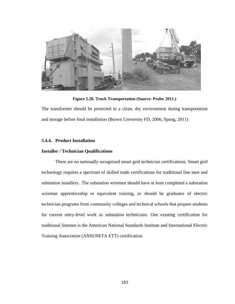
183
Figure 5.28. Truck Transportation (Source: Prolec 2011.)
The transformer should be protected in a clean, dry environment during transportation
and storage before final installation (Brown University FD, 2006; Spang, 2011)
5.4.4. Product Installation
Installer / Technician Qualifications
There are no nationally recognized smart grid technician certifications. Smart grid
technology requires a spectrum of skilled trade certifications for traditional line men and
substation installers. The substation wiremen should have at least completed a substation
wireman apprenticeship or equivalent training, or should be graduates of electric
technician programs from community colleges and technical schools that prepare students
for current entry-level work as substation technicians. One existing certification for
traditional linemen is the American National Standards Institute and International Electric
Training Association (ANSI/NETA ETT) certification.

184
Installation Codes and Standards
Agreements, Permits and Certification
Equipment installation must be carried out according to local, state, and national electric
codes. Samples of codes used for transformer installation are:
NECA 409-2009 National Electrical Installation Standards for Installing and
Maintaining Dry Type Transformers (NECA 2009)
NECA 410-2005 National Electrical Installation Standards for Installing and
Maintaining Liquid-Filled Transformers (NECA 2005)
IEEE C57.12.00-2006 IEEE Standard for Standard General Requirements for
Liquid-Immersed Distribution, Power, and Regulating Transformers (IEEE 2006)
Structure and Foundation – ASCE Substation Structural Design Guide (ASCE
2008)
NFPA 70 National Electric Codes 2011 (NEC 2011)
UL Standard 506 – Transformers (UL 2008)
UL Standard 1561 – K-rated Transformers (UL 2010)
NEMA ST1 – Specialty Transformers (NEMA 1998)
NEMA TP-1 – Guide for Determining Energy Efficiency for Dry-Type
Transformer (NEMA 2002).
Access Roads and Transportation Requirements on Site
All access roads to and from the site should be inspected for load and height
limitations. The roads to the site should be built or reinforced to hold the loads for trucks
and cranes necessary for the installation of all substation components.
185
Site Preparation
The construction site and all access roads leading to the site should be well
prepared to receive all construction loads.
Erosion Control and Fencing
The erosion and sedimentation plan should be implemented and updated to meet
site conditions. A protective fence should be constructed around the substation for
security purposes and also to meet the requirements of the SPCC. As soon as
operationally possible, the site should be secured to protect components from theft and
prevent trespassing. The fence must allow easy access to the site for delivery trucks and
cranes.
Grading and Road Improvements:
All access roads to and from the substation should be built for easy access for
heavy commercial traffic. Existing roads to be used for access to the site should be
reinforced to bear large and heavy loads. If temporary access roads are constructed, there
should be adequate erosion prevention plans and a reclamation plan in place to reclaim
the land after construction is completed. Temporary roads should be able to withstand
extreme weather conditions, including rain, sleet, and snow, and must be navigable year
round.
Crane Deployment on Site
Crane pads should be provided on site as part of site preparation. The crane
should be used in the most efficient way by scheduling several activities to be done with
limited idle time.

186
Trenching and Cable Laying
Trenches connecting the different components of the substation in the most
efficient manner should be planned. Trenching should be done in the most
environmentally responsible way and soil must be preserved and protected from erosion
and runoff into nearby bodies of water.
Transformer Oil Spill Containment (EPA 2010)
With the adoption of smart substations and the influx of high-current AC and DC,
transmission substations and their corresponding components will be larger. Oil-filled
transformers exceeding 1,320 gallons of oil will require oil containment systems per EPA
regulations.
An oil containment system or a bund system will need to be provided for oil-
cooled transformers. To be able to satisfy the requirements of an SPCC plan and to meet
oil-spill containment standards, the bund system should allow access to the transformer
for general maintenance and easy oil change maintenance by vehicles.
The bund wall should be designed to contain 115% of the maximum oil in the
transformer in addition to any rain water that might be available. Water control systems
should be installed to automatically control the water level within the bund. Sump pumps
and water control units should be able to differentiate between water and oil and must not
pump out if oil is detected. The bund should be covered to allow people standing on the
bund wall access to the transformer.

187
Figure 5.29. Transformer Pad Showing Oil Containment System Foundation
(Source: Power Engineering LLC 2011)
Figure 5.30. Oil Detection Sump Pump
(Source: www.skimoil.com 2011)
Figure 5.31. Transformer Showing Completed Oil Containment System
(Source: Case Study 3)

188
The is no requirement to build bunds around existing transformers; nevertheless,
transformers installed on or near environmentally sensitive sites with access to water
ways and bodies of water may require an oil containment system.
Power cables from the transformer should be designed to exit the bund system in a
specially designed duct. The cables should be well sealed to ensure that the bund system
is not breached during an oil spill.
Grounding Substations and Transformers
Substation grounding is probably the most important safety function performed in
the construction of the substation. The grounding must be done with expert care. Below is
a photo illustration of the process of grounding a substation.
Figure 5.32. Joining of Cables to Form a Grid
(Source: Case Study 10)
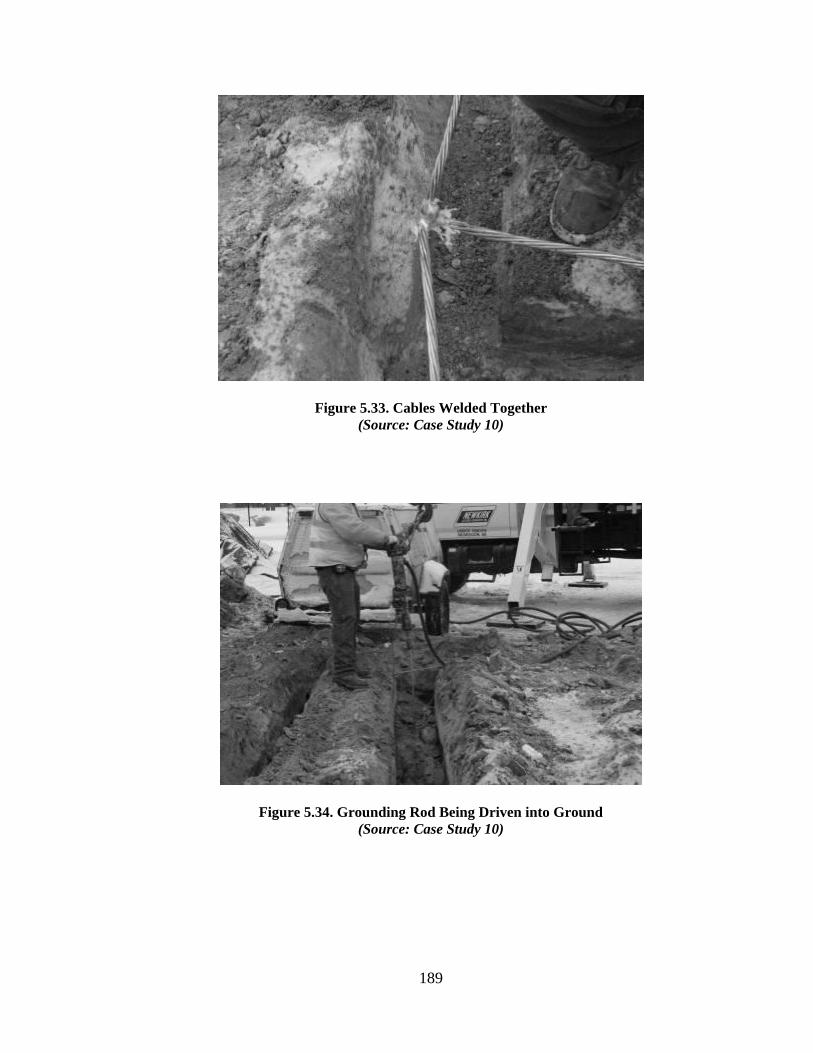
189
Figure 5.33. Cables Welded Together
(Source: Case Study 10)
Figure 5.34. Grounding Rod Being Driven into Ground
(Source: Case Study 10)

190
Figure 5.35. Joining Grounding Rods
(Source: Case Study 10)
Figure 5.36. Grounding Rod Connection
(Source: Case Study 10)
Quality Control
Quality Control should cover the following elements (ASCE 2008):
Visual inspection of the transformer,

191
Specific inspection methods for components of the transformers,
Workmanship fabrication straightness, and
Dimensional correctness.
Sound Control
If a transformer is to be installed indoors, acoustic dampening materials such as
fiberglass should be installed on the transformer room walls for indoor transformers.
Outdoor transformers should be sited as far away from residential areas as possible.
Trees and shrubs should be planted around the substation to reduce noise (Spang, 2010;
Brown FD, 2006).
Inspections
As part of the post-construction inspection, an inventory list of all the components
of the transformer should be made for easy testing and maintenance. All periodic
inspections during construction should be adhered to. These inspections should be
scheduled on the master schedule so as not to be overlooked. The Commissioning
process must be of high priority and must be undertaken according the requirements of
the NEC.
5.4.5. Design and Construction of Supporting Components
Foundations
The foundations for transformers can be either precast or cast in place. The
foundation pads should be designed to accept all normal applied and imposed loadings
without damage or settlement. Factors affecting the choice of foundation include:
Geotechnical considerations,

192
Foundation loading,
Base size of structure,
Rotation and deflection limitations,
Economics,
Aesthetics,
Contractor experience,
Equipment available,
Site accessibility, and
Bund system choice.
The design should also accommodate imposed loading resulting from installation
activities. The foundation should be designed to satisfy soil conditions on site. The pad
layout should be done accurately and must satisfy all utility, local, and state ordinances.
The pad design should be done by a professional engineer. The pad surface should be
slightly sloped to prevent water collection at the base of the transformer. The anchor bolts
should be accurately aligned.
Figure 5.37. Transformer Foundation Cast in Place
(Source: 4blogspot.com 2011)

193
Figure 5.38. Transformer Pad Foundation Precast
(Source: trenwa.com 2011)
Anchor Materials
The size and length of the anchor bolts should be determined by the engineer and all
anchor bolts should meet ASTM A 36 / A36M (ASCE 2008).
5.4.6. Construction Project Management
Project Team and Qualifications and Roles
The project team members and their qualifications will have to be clearly shown
with their respective responsibilities clearly stated (Case Study 6, 2011).
Project Estimate
The project estimate should be created. Attention should be given to the project‘s
complexity, technological requirements, team requirements, contract requirements,
duration of project, and market conditions.
Project Schedule
A detailed project schedule should be created as the baseline and maintained
throughout the duration of the project. Project schedules should include milestones for
the ordering and delivery of transformers and cranes and all testing and inspections. All

194
major milestones should be presented on the schedule. The schedule should include a
master overall schedule and have various phase schedules as needed by project crew.
Look-ahead schedules should be used for field crews, supervisors, and foremen to
recognize project stages.
Quality Assurance and Quality Control Plans
A quality assurance (QA) plan must be instituted by the constructor throughout
the duration of the project. The quality control and quality assurance programs will
depend on the complexity and size of the project. Warranties for workmanship should be
stated and backed by the contractors.
Project Controls
A project control protocol should be instituted throughout all levels of the
company. The company should adopt best practices for project controls so that the
controls system is able to identify the exact source, amount contributed by the sources,
and party or parties responsible (Syal 2011).
Safety
There should be a well-kept safety record that is verifiable over a long period of
operation. There should be dedicated safety personnel on site whose roles include (among
others):
Keeping safety manuals and procedures,
Keeping safety records (Experience Modification Risk(EMR), Days Away,
Restricted or Transferred(DART) etc.),
Keeping informed of the training requirements of labor, and
Supervising daily job safety and hazard assessments and tailgate meetings.

195
The CM and installation aspects of smart substations are summarized in Table 5.5.
5.4.7. Work Scope for Electrical Contractors
A work scope was developed for electrical contractors (EC) for smart substation
and transformer installation. The scope was developed from the CM installation matrix
(5.1), which had inputs, from data obtained from literature and case studies. The scope
was verified by the ELECTRI –NECA project task force.
The electrical contractor‘s scope of work in smart substation construction covers
the following (Details of opportunities summarized Table 5.2):
Transformer retrofits,
Installation of smart transformers,
Installation of control panels,
Construction of concrete and pier foundations,
Substation maintenance,
Switch gear maintenance and testing,
Substation grounding,
Installation of measurement components, and
Material procurement and management.

196
Table 5.5a. Checklist for Construction Management and Installations
(Overall Power System Design and Location, Planning, Zoning, and Environmental Consideration)
Construction Management and Installation
(Substation and Smart Transformers)
Level of Importance
(EC)
Responsibility
of
I.Overall Power System Design
Effect on Overall Power System Design
Power System Design
Number of step up transformers over the grid will
be reduced
Low
Designer
II. Location, Planning , Zoning and Environmental Consideration
Permits and Approvals
Permitting
Environmental enhancement and site
restoration
Safety Plans
Safety manuals and procedures
Grounding practices
Daily job hazard assessments
Spill Prevention Control
Environmental Plans
Noise Control
Erosion and Sedimentation Control
Community Education Plan
High
Owner/EC

197
Table 5.5b. Checklist for Construction Management and Installations (Product Procurement)
Construction Management and Installation (Substation
and Smart Transformers)
Level of
Importance (EC)
Responsibility of
III. Product Procurement
Transformer Procurement
Transformer Lead Time
Transportation Requirements for
Transformer Delivery
Most common transportation methods:
Truck, Railroad, Sea Carrier, and Air Carrier
Lead time for transformer depends on complexity of
design, size, worldwide demand for product, etc.
Major suppliers: ABB, Alscom, Waukesha and GE and
Howard and Cooper
High
Owner/EC /Product
Vendor
Crane Procurement Normal EC
Access Roads and Transportation on Site
Site Preparation
Erosion Control and Fencing
Grading and Road Improvements
Crane Deployment on Site
Trenching and Cable Laying
Normal
EC/Subcontractor
Sound Control Indoor transformers should have acoustic dampening
materials such as fiberglass in the transformer room.
Outdoor transformers should be sited as far from
residential areas as possible.
Trees and shrubs shield the substation as part of
environmental enhancement to reduce noise.
Normal
EC
Inspections and Commissioning Performed under NEC requirements High EC/Subcontractor

198
Table 5.5c. Checklist for Construction Management and Installations (Product Installation)
Construction Management and Installation (Substation and Smart Transformers)
Level of
Importance (EC)
Responsibil
ity of
IV. Product Installation
Installer /Technician Qualifications Transformers should be installed according to all federal, state and local codes.
ANSI NETA ETT 200
NECA 410-2009 National Electrical Installation Standards for Installing and
Maintaining Liquid-Filled Transformers. ,
EC
Installation Code and Standards NEC Sec 373-11 National Electric Code Guidelines for Installing
Transformers.
IEEE C57.12.00-2006 IEEE Standard for Standard General Requirements for
Liquid Immersed Distribution Power
UL Standard 506 – Transformers
UL Standard 1561 – K-rated Transformers
NEMA ST1 – Specialty Transformers
NEMA TP-1 Guide for Determining Energy Efficiency for Dry-Type
Transformer
Normal
EC/ Sub-
contractor
Access Road and Transportation
Requirements on Site
Site Preparation
Erosion Control and Fencing
Grading and Road Improvement
Trenching and Cable Laying
Transformer tanks above 1320 gallon require an oil spill system
Sump pumps and dewatering systems should differentiate between water and oils
during spills
Bund should be covered to allow access
Power cables should be well sealed to ensure that system is not breached during an oil
spill
High
EC
Transformer Oil Spill
Containments System
Grounding practices should be clearly illustrated and well documented as part of the
company safety practices.
All project grounding design adhered to and strictly followed
High
EC
Quality Control Company safety manuals and procedures well documented (EMR and DART records)
Periodic safety training for labor
Daily job safety and hazard assessments and tailgate meetings
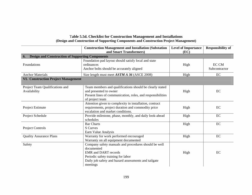
199
Table 5.5d. Checklist for Construction Management and Installations (Design and Construction of Supporting Components and Construction Project Management)
Construction Management and Installation (Substation
and Smart Transformers)
Level of Importance
(EC)
Responsibility of
6. Design and Construction of Supporting Components
Foundations
Foundation pad layout should satisfy local and state
ordinances
Anchor bolts should be accurately aligned
High
EC CM
Subcontractor
Anchor Materials Size length must meet ASTM A 36 (ASCE 2008) High EC
VI. Construction Project Management
Project Team Qualifications and
Availability
Team members and qualifications should be clearly stated
and presented to owner
Present lines of communication, roles, and responsibilities
of project team
High
EC
Project Estimate
Attention given to complexity in installation, contract
requirements, project duration and commodity price
escalation and market conditions.
High
EC
Project Schedule
Provide milestone, phase, monthly, and daily look-ahead
schedules
High EC
Project Controls
Bar Charts
S Curves
Earn Value Analysis
High EC
Quality Assurance Plans Warranty for work performed encouraged
Warranty on all equipment documented
High EC
Safety Company safety manuals and procedures should be well
documented
EMR and DART records
Periodic safety training for labor
Daily job safety and hazard assessments and tailgate
meetings
High
EC

200
Table 5.6. Work Scope of Electrical Contractors for Smart Substation and Smart Transformers
Work scope of Electrical Contractors for Smart Substations and Smart Transformers
Self-Performed Subcontractors Consultant
Substation/Transformer Retrofitting
Installing HTS Transformers
Installing Measurements Components
Spill Prevention Control and
Countermeasure Plans
Consulting and Training
Project Management
Specifications Development
Specialized Equipment Delivery and
Installation
Circuit Breakers
HTS Transformers
Line Tracker Community Meter
Phasor Measurement Units
Wide Area Monitoring Systems
(WAMS)
Substation Automation Sensors
SCADA systems
Distribution Monitoring Systems
(DMS)
Supplier Evaluation and Analysis
Site Works
Excavating and Backfilling
Land Reclamation
Stripping and Clearing
Grading
Excavation
Drainage
Dewatering
Fencing
Access Roads
Installing HTS Transformers
Communication Systems Installations
Erosion and Sedimentation Control
Concreteworks
Foundations
Piers
Culverts
Environmental Planning
Land Reclamation
Erosion and Sedimentation Control
Spill Prevention Control and
Countermeasure Plans
Community Education Plan
Surveying and Right of Way Engineering
Consultants
Environmental
Design
Communication Systems and
Information Technology
Workforce Training
Surveying and Right of Way
Engineering
Community Education Plans
Consulting and Training

201
5.5. AUTOMATED/ADVANCED METERING INFRASTRUCTURE (AMI)
An automated/advanced metering infrastructure (AMI) is an integration of several
technologies. It consists of four main components: a smart meter at the customer‘s
location, a communications network between the utility company and the smart meter,
the home area network, and the data management software installed by the utility
company to track and control the communication and electric flow and serve as
interconnection to automated utility billing between the utility company and the
consumer (EPRI 2007, Hart 2008). However, more technologies can be built into the
systems, such GIS and data management applications (Case Study 7, 2011).
An AMI enables utility companies to undertake demand response at the customer
level by giving consumers the ability to make informed decisions (NETL 2008). The
home area network gateway reads and links the meter to various end use devices and
communicates with the service provider. Installation of an AMI can be considered under
the following:
The installation and retrofitting of electric smart meters,
Installation of sensing, measurement, and advanced components on the
distribution network, and
The development, installation, and implementation of a data management system
or a SCADA system.
Smart Meters
The installation and retrofitting of smart meters is one of the most important
aspects of deploying smart technology, as it is the main interaction between the utility
company and the consumer. Due to this sensitivity to customer opinions and acceptance,

202
the planning for smart meter installation and retrofitting is the most critical part of any
smart grid technology adaptation.
5.5.1. Overall Power System Design
NA
5.5.2. Location, Planning, Zoning, and Environmental Considerations
NA
5.5.3. Product Procurement
Utility companies procure smart meters under three main methods (Case Study 7,
2011):
In-house procurement and deployment,
Outsourcing to vendors and subcontractors, and
A hybrid solution between the two systems.
The decision to either outsource the procurement and/or the installations of smart
meters by a utility company is determined by several factors including the existence of an
in-house installation capability or expertise in the company. When the procurement and
installation of smart meters are outsourced to vendors or manufacturers, these
manufacturers in turn sublet the installation of the meters to subcontractors. The vendors
are usually supervised by the project management department of the utility company.

203
Smart Meter Standards
Smart meter installation is regulated under the ANSI C12 (ANSI 2008), which
describes the protocol for meters that employ the use of two-way communications in the
American market.
5.5.4. Product Installation
The installation of smart meters is of importance to utility companies, as is the
gateway to the HAN. The smart meter is also the first point of contact between the utility
company and the consumer. Those who install the smart meters are indirectly the
representatives of the company, and must exhibit all the professionalism that would be
exhibited by an employee of the utility company.
Problems can be reduced or avoided with critical planning for smart meter
installations. Smart meter installations and wireless communication stations can be
planned with the use of GIS and GPS for more efficient installation and tracking. Route
optimization software can be combined with scheduling software for an efficient
deployment. The smart meter installation process is illustrated in Figures 5.12 – 5.14.

204
Figure 5.39. Image Installing a Smart Meter
(Source: Pepco 2011)
Easily accessible programs such as Google Earth can be used to ensure the
accurate siting and location of the poles and towers on which wireless communication
systems will be installed to ensure the most effective coverage. These programs can also
be used for the efficient planning of smart meter installations.
205
Cell Relays
The installation of cell relays on poles and at communication centers requires
specialized electrical installation knowledge. This is either done by the line workers of
utility companies or can be outsourced to electrical contractors who can prove they
understand the philosophy and workings of a utility company, and can install these
components at a lower cost than their competitors (Case Study 7, 2011).
Cell relays are installed on poles at determined intervals to monitor and transfer
data from the grid to a control center. The specific communication technology adopted
will be determined by the utility company, and this will determine the installation
processes to be used.
Installer / Technician Qualifications
No qualifications are needed for installing smart meters. However, for one to be
able to install cell relays and other complicated electrical components, one needs to be a
qualified electrician in the state of operation.
Installation Codes and Standards
ANSI C12 (ANSI 2008)
5.5.5. Construction Project Management
Free software such as Google Earth or more complicated GIS programs can be
used to identify and site cell towers on which cell relays will be installed and used to find
the most efficient ways of deploying smart meters at homes and commercial premises
(Case Study 14, 2011).

206
Scheduling
Scheduling for the installation of smart meters can be a very important tool to the
EC as it can aid in reporting work progress to the utility company and electrical
contractor. Scheduling optimization software will ensure that field technicians with the
right skills are dispatched to install the smart meters and cell relays with little disruption
to customer power supplies (Morris, 2011). The use of scheduling software like
Primavera and M S Projects can be used in combination with GIS.
Figure 5.40. Using Google Earth to Plan Siting of GSM Relay Tower Points (Source Google
Earth)
For the EC to add value as an installer of AMI technologies, they need to operate
like an agent of the utility company and adopt the standards of the utility company in
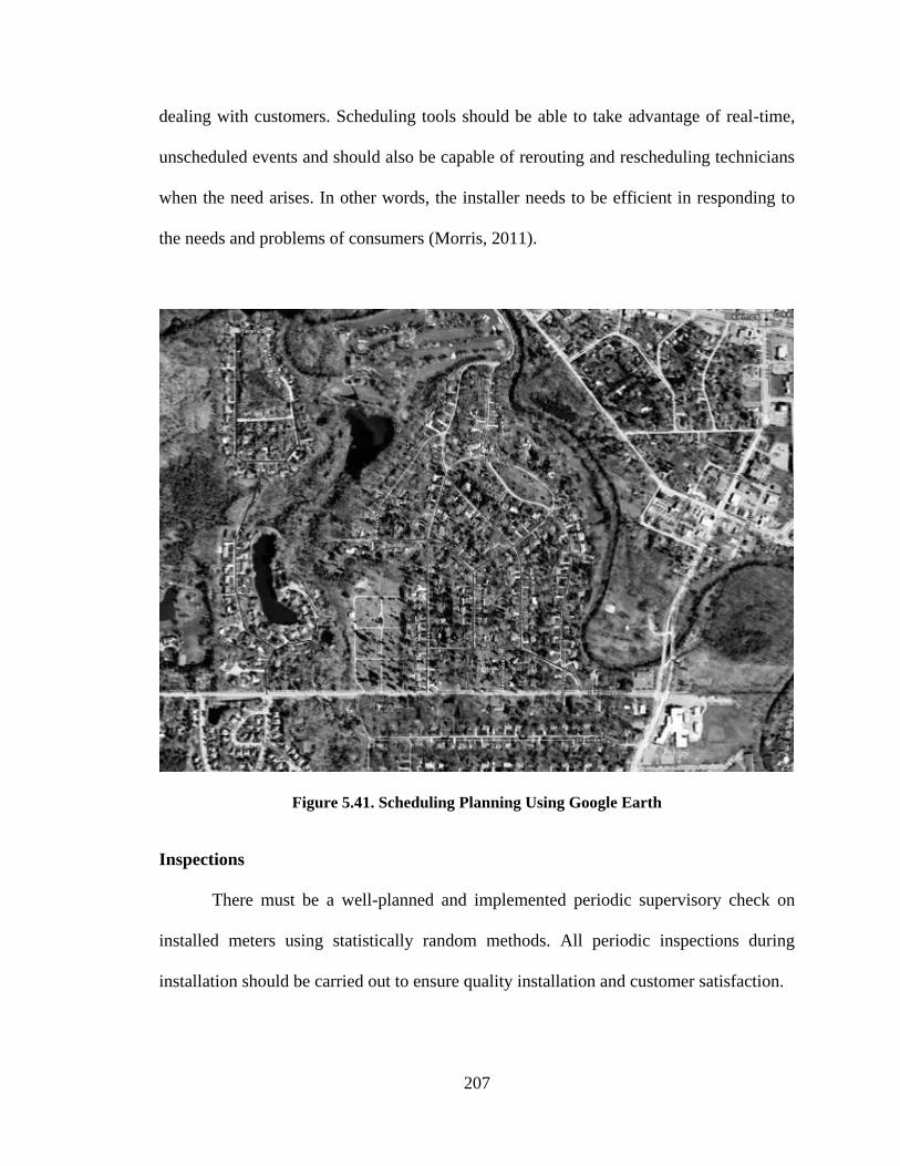
207
dealing with customers. Scheduling tools should be able to take advantage of real-time,
unscheduled events and should also be capable of rerouting and rescheduling technicians
when the need arises. In other words, the installer needs to be efficient in responding to
the needs and problems of consumers (Morris, 2011).
Figure 5.41. Scheduling Planning Using Google Earth
Inspections
There must be a well-planned and implemented periodic supervisory check on
installed meters using statistically random methods. All periodic inspections during
installation should be carried out to ensure quality installation and customer satisfaction.
208
Installation of Smart Components on the Distribution Network
The EC will have to stay abreast of current measurement technologies on the
distribution grid to be able to install, monitor, maintain, and deploy such technologies in
the most efficient way possible. Some of the measurement technologies that might be
needed will include measurement components like line RF temperature, current sensors,
relay cells, and line-tracking communicating meters.
5.5.6. Work Scope of Electrical Contractors
A work scope was developed for the EC for AMI installations. The work scope was
developed from case study visits and literature reviewed. The work scope was verified by
the case study participants and by the NECA-ELECTRI taskforce. The work scope of EC
includes the following duties:
Installing SCADA systems,
Installing cell relays,
Installing smart meters,
Installing measurement technologies, and
Installing cell /communication towers.

209
Table 5.7a. Checklist for Construction Management and Installations
(Overall Power System Design and Location, Planning, Zoning Environmental Considerations, and Product Procurement)
Construction Management and Installation (AMI) Level of
Importance (EC)
Responsibility of
I. Overall Power System Design
NA NA NA NA
II.Location, Planning , Zoning and Environmental Consideration
NA NA NA NA
III. Product Procurement
AMI Delivery Methods (Utilities)
Top Five US Smart Meter Manufacturers
(Berst, 2010)
Smart Meter Standards (ANSI 2008)
Communication Technologies (Refer to
Chapter 4 )
Delivery methods used for AMI installations:
Utility Procurement and Deployment
Vendor Procurement and Deployment
Utility Procurement and Contractor Deployment
Itron, Landis Gyr, Sensus, Elster, and General Electric
ANSI C12 (ANSI 2008)
Broadband Over Power Line
Wireless
Miscellaneous
High
EC /Subcontractor
/Supplier

210
Table 5.7b . Checklist for Construction Management and Installations
(Product Installation, Design and Construction of Supporting Components, and Construction Project Management)
Construction Management and Installation (AMI) Level of
Importance (EC)
Responsibility
of
IV. Product Installation
Installer /Technician
Qualifications Smart Meters
Cell Relays
No qualifications for installing smart meters
ANSI /NETA ETT 2000
Installation Code and Standards ANSI C12
NFPA 70 National Electric Codes 2011
EC/Subcontract
or
Quality Control Specific inspection methods for components of the transformer
Workmanship checks
High EC
V . Design and Construction of Supporting Components
NA NA
NA NA
VI. Construction Project Management
Project Team Qualifications and
Availability
Team members and qualifications should be clearly stated and
presented to owner as part of project bids.
High EC
Project Estimate
Attention given to complexity in installation, contract requirements,
project duration, commodity price escalation, and market
conditions.
High EC
Project Schedule
Provide milestone, phase, monthly, and daily look-ahead schedules
to owners, PM, supervisors, etc.
High EC
Project Controls
Bar Charts
S Curves
Earn Value Analysis
High EC
Quality Assurance Plans Warranty for work performed encouraged
Warranty on all equipment documented
High EC
Safety Company safety manuals and procedures well documented
EMR and DART records
Periodic safety training for labor
High EC
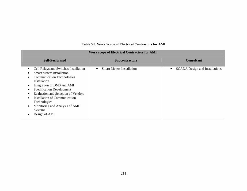
211
Table 5.8. Work Scope of Electrical Contractors for AMI
Work scope of Electrical Contractors for AMI
Self-Performed Subcontractors Consultant
Cell Relays and Switches Installation
Smart Meters Installation
Communication Technologies
Installation
Integration of DMS and AMI
Specification Development
Evaluation and Selection of Vendors
Installation of Communication
Technologies
Monitoring and Analysis of AMI
Systems
Design of AMI
Smart Meters Installation SCADA Design and Installations
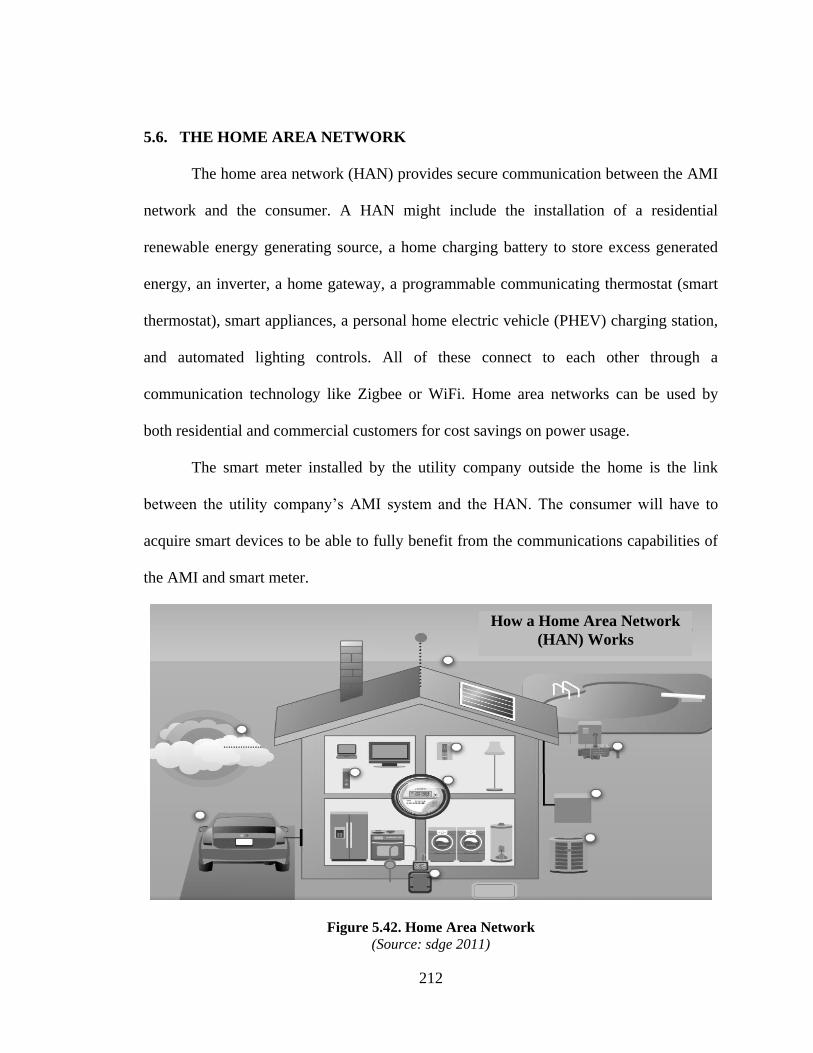
212
5.6. THE HOME AREA NETWORK
The home area network (HAN) provides secure communication between the AMI
network and the consumer. A HAN might include the installation of a residential
renewable energy generating source, a home charging battery to store excess generated
energy, an inverter, a home gateway, a programmable communicating thermostat (smart
thermostat), smart appliances, a personal home electric vehicle (PHEV) charging station,
and automated lighting controls. All of these connect to each other through a
communication technology like Zigbee or WiFi. Home area networks can be used by
both residential and commercial customers for cost savings on power usage.
The smart meter installed by the utility company outside the home is the link
between the utility company‘s AMI system and the HAN. The consumer will have to
acquire smart devices to be able to fully benefit from the communications capabilities of
the AMI and smart meter.
Figure 5.42. Home Area Network
(Source: sdge 2011)
How a Home Area Network
(HAN) Works
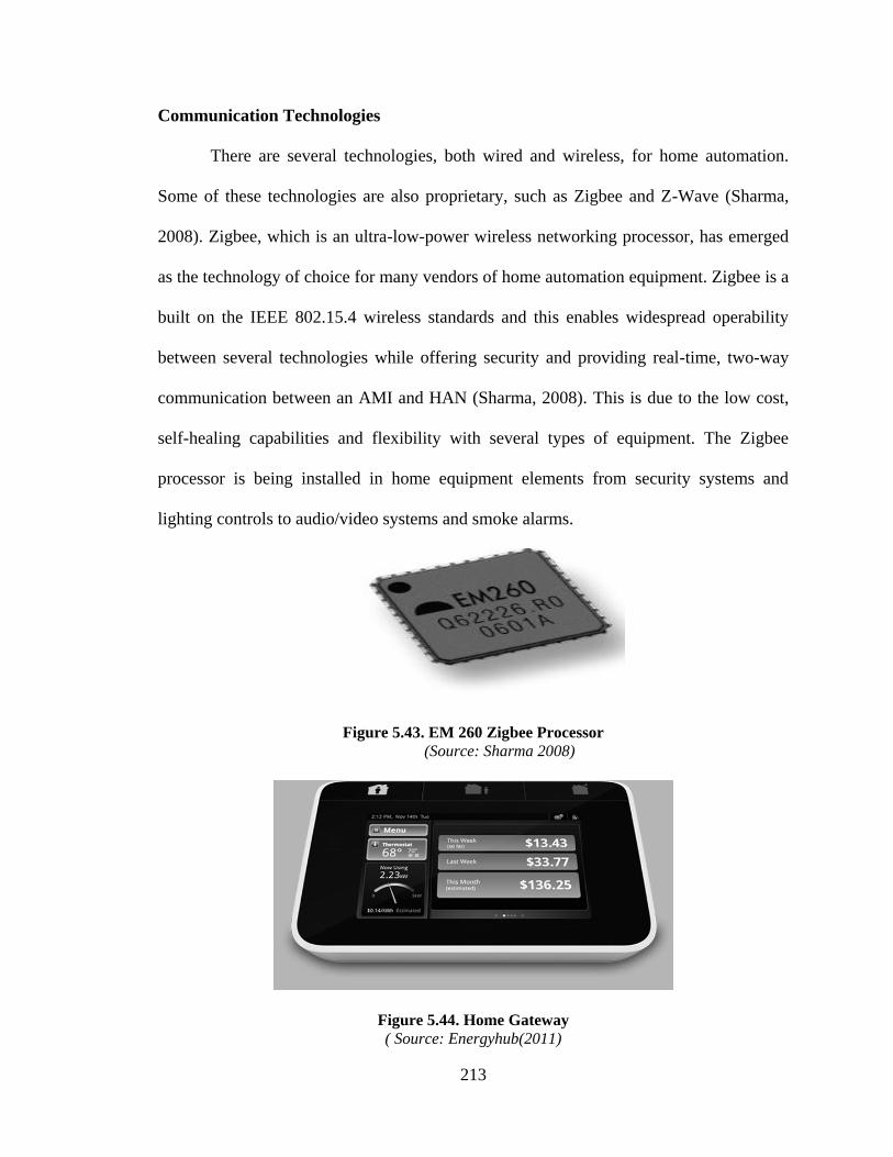
213
Communication Technologies
There are several technologies, both wired and wireless, for home automation.
Some of these technologies are also proprietary, such as Zigbee and Z-Wave (Sharma,
2008). Zigbee, which is an ultra-low-power wireless networking processor, has emerged
as the technology of choice for many vendors of home automation equipment. Zigbee is a
built on the IEEE 802.15.4 wireless standards and this enables widespread operability
between several technologies while offering security and providing real-time, two-way
communication between an AMI and HAN (Sharma, 2008). This is due to the low cost,
self-healing capabilities and flexibility with several types of equipment. The Zigbee
processor is being installed in home equipment elements from security systems and
lighting controls to audio/video systems and smoke alarms.
Figure 5.43. EM 260 Zigbee Processor
(Source: Sharma 2008)
Figure 5.44. Home Gateway
( Source: Energyhub(2011)

214
Figure 5.45. Programmable Communicating Thermostat
(Source: Designboom 2011)
5.6.1. Impact on Overall Power System Design
A fully operational HAN will enable two-way communication between the
consumer and the utility company. This enables the utility company to have a more
efficient planning protocol for its distribution assets. This will reduce operational costs by
eliminating redundant generation and substation assets (Case Study 16, 2011).
5.6.2. Location, Planning, Zoning, and Environmental Considerations
There are no special permitting requirements for installing smart equipment like
appliances in the home beyond the safety requirements stipulated in the National
Electrical Codes. However, there are permitting requirements for installing solar panels
and micro wind turbines on homes or on commercial buildings. Some states are exploring
the integration of residential renewable generation sources to the grid for net metering
purposes and are amending their building codes to accommodate the increasing interest in
the installation of charging stations in homes.

215
5.6.3. Product Procurement
Several companies are combining technologies such as Zigbee, WiFi, and cellular
wireless technologies to come up with centrally controlled home area applications for
homes and commercial buildings. Companies are continually partnering with electrical
companies to serve as vendors and installers for their technologies. Several companies
have developed stand-alone systems that control all the home area technologies from a
single source.
5.6.4. Product Installation
Installation Standards
To install a photovoltaic (PV) system, local building codes, zoning ordinances,
and subdivision covenants must be followed. This is mostly governed at the local level
(USDOE 2009). The authority with jurisdiction, usually the building department of a city
or state, must have codes that comply with the National Electric Code (National Fire
Protection Association 70) with regard to all electrical work on homes and businesses.
Article 690 of the NEC specifically applies to the installation of photovoltaic systems
(Chiras et al., 2009). Article 690 has been in the National Electric Code since 1984 (IAEI
1999).
There are no new standards for installing most of the components of a HAN
besides the typical qualifications for electricians as determined by the state of operation.
For solar installations, however, there are upcoming qualifications for installers from the
North American Board of Certified Energy Practitioners (NABCEP) and the Interstate

216
Renewable Energy Council (IREC) Institute for Sustainable Power Quality (ISPQ)
retraining certifications.
Due to the complexity of PV systems, DOE recommends customers seriously
consider having a professional solar contractor install the system (DOE 2009).
Experience in installing grid-connected systems is especially useful due to the extra
installation steps such as interconnection with the grid. The contractor should have an
electrical contractor‘s license. Certain solar rebate programs may also require specific
certification (DOE 2009).
Contracting for commercial solar installations for buildings is a more complex
process. The installation of solar arrays will usually be contracted using one of the
existing delivery systems. This will usually involve several project participants such as
designers, rack manufacturers and installers, and inverter vendors and installers, for
example.
Solar
The main components of a residential solar installation are mounting structures,
power conditioners, and an on-site energy storage device.
Inverters
An inverter converts the generated DC into AC and synchronizes with the
electricity in the grid (Solar Direct 2010). Inverters are used in conjunction with charge
controllers to protect the battery from overcharging (USDOE 2010).

217
Figure 5.46. Inverter (left) and Charge Controller (right)
(Source: EERE 2011)
Electricity Storage
The electricity storage, or the batteries, is where PV cells store excess energy.
These batteries can be tapped for electricity when the PV cells do not provide a
sufficient amount of energy (i.e. on a cloudy day). Battery banks are expensive and
lower the overall efficiency of the PV system; only about 80% of the energy that goes in
can be reclaimed (USDOE 2008). Regardless, batteries are a way to store excess PV
energy, and are a necessity for off-the-grid PV systems.
5.6.5. Design and Construction of Supporting Components
There are four types of mounting structures: roof/ground, top of pole, side of pole,
and tracking mounts (AltE University 2010). The first three types are fixed; this means
the solar panels are fixed in a position according to the latitude and longitude of the
location that receives the maximum amount of sunlight.
Rack mounts can be used on the ground or on flat or sloped roofs. Racks are
primarily made out of aluminum and consist of three main parts: the anchors that keep
the rack attached to the surface, the legs that provide the tilt of the panels, and the

218
horizontal bars to which the PV modules are attached. Rack mounts are relatively easy to
install. If the surface is the ground, te legs of the rack must be firmly anchored into a
foundation, usually concrete piers or pilings set in the ground.
The mounting structures should be strong enough to bear the weight of the PV
arrays in all prevailing weather conditions. Before arrays are installed on roofs, the roofs
should be inspected to ensure they can withstand the additional weight of the arrays and
the mounting structure.
Rack mounts can also be installed on a roof. Metal L-footings and lag screws are
used to attach the mount to the roof.
Figure 5.47. L-Footings Bolted to a 2x4 Block Attached to Adjacent Roof Rafters
(Source: Chiras et al., 2009)
Silicon caulk should be applied around the footing and screws to prevent rain or snow
from penetrating the roof.
5.6.6. Construction Project Management
Refer to Table 5.9.
219
5.6.7 Work Scope of Electrical Contractors
A work scope was developed for EC for ESD. This work scope was developed
from literature and verified by the ELECTRI-NECA task force. The work scope for ESD
includes the delivery and installation of:
Load Control Receivers,
Automated Lighting and Controls,
Roof Solar Installations,
Home Batteries,
Micro Wind Turbines,
PHEV Charging Points,
Communication Technologies, and
Smart Appliances.

220
Table 5.9a. Checklist for Construction Management and Installations
(Overall Power System Design, Location, Planning, Zoning, Environmental Considerations, and Product Procurement)
Construction Management and Installation of Home
Area Network (HAN)
Level of
Importance (EC)
Responsibility of
I. Overall Power System Design
Effect on Overall Power System Design Enables two-way communication between the
consumer and the utility company.
Low
II. Location, Planning , Zoning and Environmental Consideration
Permits and Approvals
Building Codes
National Electric Codes(National Fire Protection
Association 70)
High Owner/EC
III. Product Procurement
Commercially Available Components
Home Area Networks
Home Gateway
Programmable Communicating Thermostat (Smart
Thermostat)
Automated Light Controls
High Owner/EC
/Product Vendor
Inspections and Commissioning Performed under NEC requirements High EC/Subcontractor

221
Table 5.9b. Checklist for Construction Management and Installations (Product Installation)
Construction Management and Installation Home Area
Network (HAN)
Level of
Importance (EC)
Responsibility
of
IV. Product Installation
Installer/Technician
Qualifications National American Board of Certified Energy Practitioners
(NABCEP)
Interstate Renewable Energy Council (IREC) Institute for
Sustainable Power Quality (ISPQ) Training/Retraining
Certification
Installation Code and Standards Building Codes
National Electric Codes Section 90
Photovoltaic Power Systems and National Electric Code:
Suggested Practices. SANDIA Report SAND 96-2797
(SANDIA 1996)
EC
Quality Control Visual inspection of all components delivered to site
Specific inspection methods for components of the HAN
Strict adherence to manufacturers recommended installation
processes
High EC

222
Table 5.9c. Checklist for Construction Management and Installations
(Design and Construction Supporting Components and Construction Project Management)
Construction Management and Installation Home Area
Network (HAN)
Level of
Importance (EC)
Responsibility of
V. Design and Construction of Supporting Components
Mounting Structures Racks should be securely secure to roof.
Racks installed on the ground should be securely installed
into a foundation.
Racks should be inspected before cells are installed
Silicon caulk should be applied around all footings and
screws adjoining the roof.
High EC/ CM
Subcontractor
VI. Construction Project Management
Project Team Qualifications and
Availability
Team members and qualifications should be clearly stated
and presented to owner
High EC
Project Estimates
Attention given to complexity of installation, contract
requirements, project duration, commodity price escalation,
and market conditions, especially steel and aluminum for
racks.
High EC
Project Schedule
Provide milestone, phase, monthly, and daily look-ahead
schedules
High EC
Project Controls
Bar Charts
S Curves
Earn Value Analysis
High EC
Quality Assurance Plans Warranty for work performed encouraged
Warranty on all equipment documented
High EC
Safety Company safety manuals and procedures well documented
EMR and DART records
Periodic safety training for labor
Daily job safety and hazard assessments and tailgate
meetings (Commercial Installations)
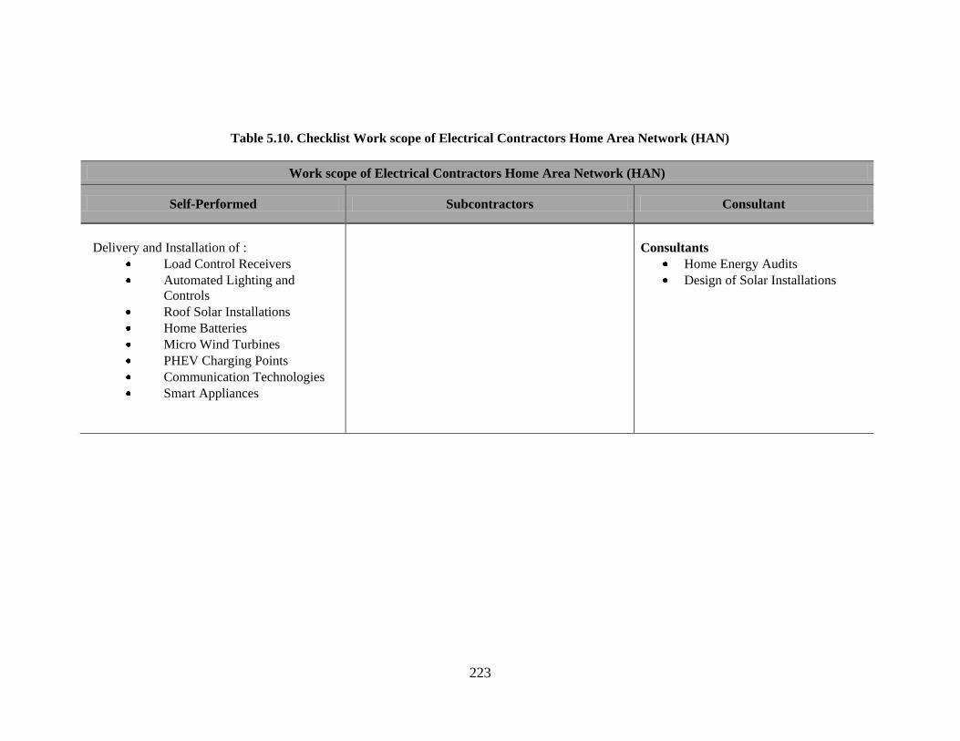
223
Table 5.10. Checklist Work scope of Electrical Contractors Home Area Network (HAN)
Work scope of Electrical Contractors Home Area Network (HAN)
Self-Performed Subcontractors Consultant
Delivery and Installation of :
Load Control Receivers
Automated Lighting and
Controls
Roof Solar Installations
Home Batteries
Micro Wind Turbines
PHEV Charging Points
Communication Technologies
Smart Appliances
Consultants
Home Energy Audits
Design of Solar Installations

224
5.7. MISCELLANEOUS TECHNOLOGY: PLUG-IN ELECTRIC VEHICLE
CHARGING STATIONS
According to Becker and Sidhu (2009), plug-in hybrid and plug-in electric
vehicles will constitute 64% of light vehicle sales and 24% of light vehicle fleets in the
U.S. by 2030. This will make the servicing of these vehicles imperative. The provision of
smart charging stations will be one of the biggest changes in the coming years. Charging
stations can be separated into the public commercial charging and home charging
stations. In America, unlike other parts of the world, it is estimated that home charging
outlets will constitute the majority of charge stations by 2015 (Pike Research 2010).
However, there will be a corresponding demand for commercial charging stations as
home charging station demand increases.
Home charging stations are considered as level 1and level 2 stations and are
divided into two kinds, mainly for overnight charging in individual homes and overnight
charging in apartment complexes (Morrow et al., 2008). Commercial charging stations
are considered as level 2 and level 3 with emphasis on fast and safe charging for
commuters.
5.7.1 Impact on Overall Power System Design
Charging stations do not yet have the volume to have any effect on the grid as a
whole. However, if the rate of construction continues to increase and there are several
charging stations on the grid, then this will affect the way electricity is used. For
example, if there are many cars parked and getting charged on the grid overnight, then
the rates from the utility companies might have to increase due to the load demands from
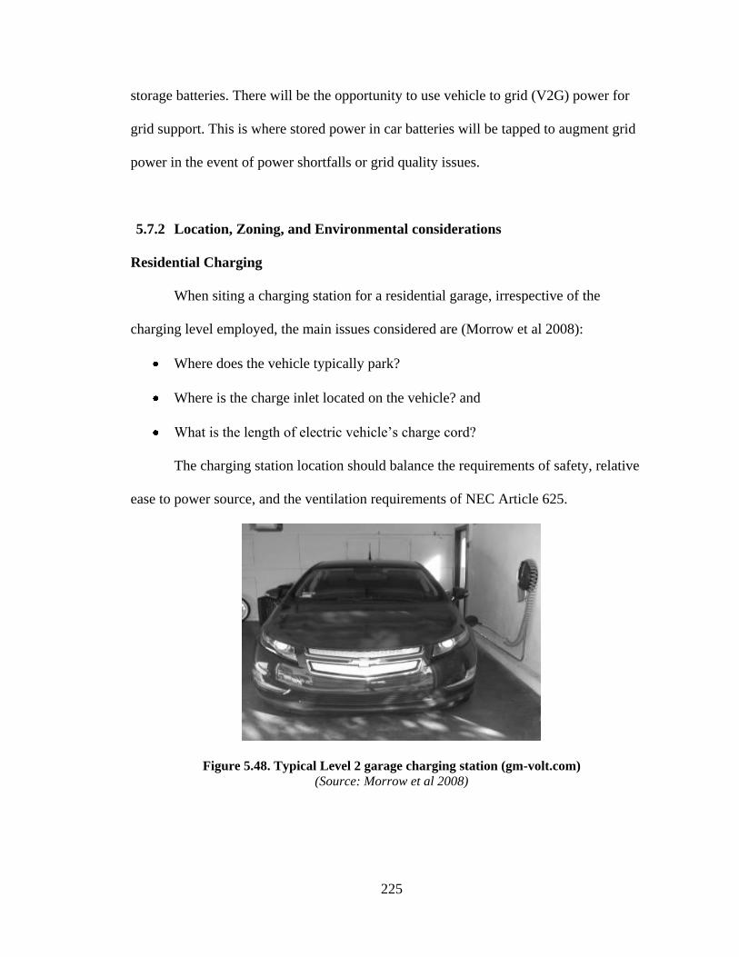
225
storage batteries. There will be the opportunity to use vehicle to grid (V2G) power for
grid support. This is where stored power in car batteries will be tapped to augment grid
power in the event of power shortfalls or grid quality issues.
5.7.2 Location, Zoning, and Environmental considerations
Residential Charging
When siting a charging station for a residential garage, irrespective of the
charging level employed, the main issues considered are (Morrow et al 2008):
Where does the vehicle typically park?
Where is the charge inlet located on the vehicle? and
What is the length of electric vehicle‘s charge cord?
The charging station location should balance the requirements of safety, relative
ease to power source, and the ventilation requirements of NEC Article 625.
Figure 5.48. Typical Level 2 garage charging station (gm-volt.com)
(Source: Morrow et al 2008)

226
Commercial Charging
For apartment complexes, siting consideration is given to parking locations.
Typically, there are distribution points at each complex for distribution to individual
apartments. Usually circuit protection will have to be installed to protect the charging
units because the fuse panels are usually installed in the apartments (Morrow et al.,
2008).
Figure 5.49 – Distribution Point of an Apartment Complex
(Source:Morrow et al 2008)
Commercial Charging Stations
Commercial facilities typically have a single utility service entrance, with power
distributed to several subpanels throughout the building. New meters and accounts will
need to be established with the power company to service only the charging station.
However, when this approach is taken, the cost should be charged to the customer as part
of the contract. The location of a charging station should be easily accessible and easy to
find (Morrow et al., 2008).

227
5.7.3. Product Procurement
The main vendors and installers of PHEV stations according to Morris et al
(2011) are:
Ecotality,
Clipper Creek,
Aeroveironment,
Coulomb,
General Electric,
Pep Stations,
Better Place, and
Leviton.
5.7.4. Product Installations (Morrow et al., 2008)
Installation Standards
Several jurisdictions are developing installation standards for electric vehicle
charging stations. Existing installation standards are:
UL 2202, the Standard for Safety of Electric Vehicle (EV) Charging System
Equipment (UL 2009).
National Electric Codes (NEC) Section 625 (NEC 2011).
Charging Garages
Residential charging outlets consist of a dedicated standard 15–20 Amp breaker
on a 120V circuit with a ground fault interrupter for a level 1 charger or a dedicated 40
Amp or higher rated 240V circuit for a level 2. For commercial stations, only level 2 and

228
level 3 stations require a dedicated 60 Amp or higher 480V circuit with special grounding
equipment (Morrow et al., 2008). There must be coordination with utility companies to
establish dedicated meters for commercial installations
Accessibility
Commercial charging stations are required under the Americans with Disabilities
Act to provide accessible parking spots for disabled patrons. This spot must be provided
solely for the use of persons with disabilities and must be appropriately labeled with the
recommended signage.
Lighting and Shelter
For commercial charging stations, lighting is recommended for convenience and
safety. This especially needed in isolated charging stations.
Signage
There should be signs directing drivers to the charging station stalls and signs
indicating that the parking spaces are exclusively for charging.
5.7.5. Design and Construction of Supporting Components
NA
5.7.6. Construction Project Management
NA

229
5.7.7. Works Scope of Electrical Contractors
A work scope was developed for EC for installing PHEV charging stations. This
work scope was developed from literature and verified by the ELECTRI-NECA task
force. The work scope for ESD includes the delivery and installation of the following:
Installation of Charging Stations (Residential and Commercial)
Design and Building of Commercial Charging Lots
Material Procurement
Construction Management
Specification Development
Vendor Evaluations and Selection

230
Table 5.11a. Checklist for Construction Management and Installations
(Overall Power System, Design, Location, Planning, Zoning, Environmental Considerations, and Product Procurement)
Construction Management and Installation PHEV
Charging Stations
Level of
Importance (EC)
Responsibility of
I. Overall Power System Design
Effect on Overall Power System Design Vehicle-to Grid-Capabilities Low
II. Location, Planning , Zoning and Environmental Consideration
Siting Considerations
Where car regularly parks
Location of charge outlet on car
Length of charging cords
Ventilation requirements
Safety
Location to distribution boxes
High Owner/EC
III. Product Procurement
Vendors and Installations U.S. Market Leaders (Morrow et al., 2008):
Ecotality
Clipper Creek
Aeroveironment
Coulomb
General Electric
Pep Stations
Better Place
Leviton
High Owner/EC/Product
Vendor

231
Table 5.11b. Checklist for Construction Management and Installations (Product Installation)
Construction Management and Installation PHEV Charging
Stations
Level of
Importance (EC)
Responsibility
of
IV. Product Installation
Installer/Technician Qualifications Qualified Electricians
Installation Code and Standards UL 2202, The Standard for Safety of Electric Vehicle(EV)
Charging System Equipment (UL 2009)
National Electric Codes Section 625 (NEC 2011)
EC
Charging Garages Dedicated outlets with circuit breakers (15–20 Amp on 120V level
1 and 40 Amp on 240V for level 2, 60 Amp 480 circuit for level 3)
Normal EC/
Subcontractor
Grounding Grounding practices should be clearly illustrated and well
documented as part of the company safety practices.
All project grounding design adhered to and strictly followed as
stipulated by manufacturers and NEC
High EC
Accessibility Charging spots for those with disabilities should be provided for
commercial charging stations under the American with Disabilities
Act (ADA)
High EC
Lighting, Shelter, and Signage Adequate lighting and signage should be provided for commercial
installations.
High EC
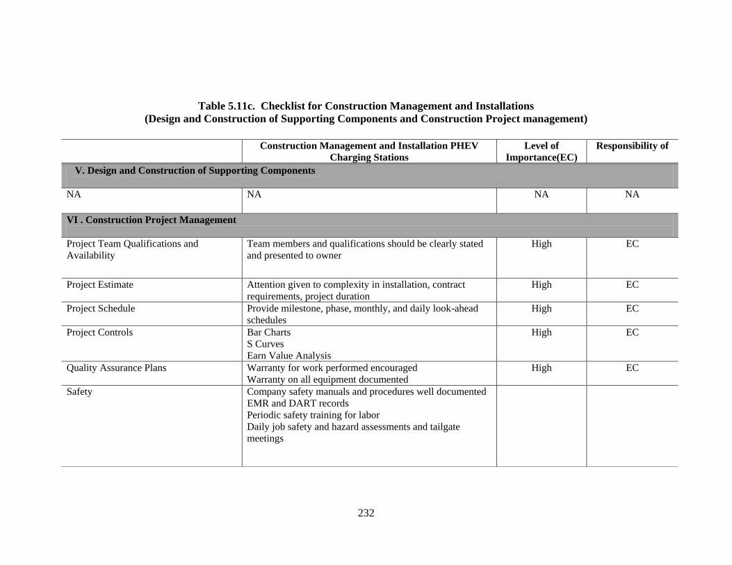
232
Table 5.11c. Checklist for Construction Management and Installations
(Design and Construction of Supporting Components and Construction Project management)
Construction Management and Installation PHEV
Charging Stations
Level of
Importance(EC)
Responsibility of
V. Design and Construction of Supporting Components
NA NA NA NA
VI . Construction Project Management
Project Team Qualifications and
Availability
Team members and qualifications should be clearly stated
and presented to owner
High EC
Project Estimate
Attention given to complexity in installation, contract
requirements, project duration
High EC
Project Schedule
Provide milestone, phase, monthly, and daily look-ahead
schedules
High EC
Project Controls
Bar Charts
S Curves
Earn Value Analysis
High EC
Quality Assurance Plans Warranty for work performed encouraged
Warranty on all equipment documented
High EC
Safety Company safety manuals and procedures well documented
EMR and DART records
Periodic safety training for labor
Daily job safety and hazard assessments and tailgate
meetings
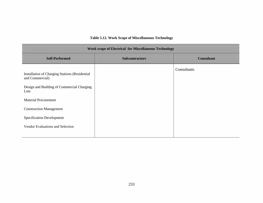
233
Table 5.12. Work Scope of Miscellaneous Technology
Work scope of Electrical for Miscellaneous Technology
Self-Performed Subcontractors Consultant
Installation of Charging Stations (Residential
and Commercial)
Design and Building of Commercial Charging
Lots
Material Procurement
Construction Management
Specification Development
Vendor Evaluations and Selection
Consultants
234
5.8. SUMMARY
This chapter explored the installation and construction management (CM) aspects
of the five smart grid related technologies identified. The technologies considered were
smart substation and smart transformers, automated metering infrastructure (AMI),
advanced superconducting transmission cables, energy storage devices, and home area
networks. The CM aspects for the respective technologies were considered under the
categories of impact on the overall power system design; location, planning, zoning, and
environmental considerations; product procurement; product installation; design and
construction of supporting components; and construction project management.
Based on the previously mentioned technologies and the categorizations, a matrix
was compiled for each technology and the work scope of electrical contractors was
compiled.
235
CHAPTER 6
SUMMARY AND CONCLUSIONS
6.1. OVERVIEW
This research analyzed and explained the installation and construction
management aspects of smart grids, with a focus on electrical contractors. To enhance the
understanding of these construction management and installation aspects, major smart
grid initiatives undertaken by stakeholders were identified. Smart grid technologies,
existing and emerging, were categorized into five main categories. Five technologies
were selected, and the construction management and installation aspects, as well as the
work scope relating to electrical contractors, were developed. These technologies were
chosen following informal discussions with members of the ELECTRI-NECA task force
and its case study respondents.
The research need, goal, objectives and key work steps, as well as the scope and
overall limitations, were presented in chapter one. Chapter two presented a summary of
the relevant literature. Chapter three presented major initiatives by stakeholders. Chapter
four presented smart grid technologies, emerging and existing. Chapter five outlined the
construction management and installation requirements that have been developed for the
five technologies selected by the researcher.
This chapter summarizes the overall research output. It is followed by the
research conclusion and, finally, potential areas for future research.

236
6.2. SUMMARY OF OBJECTIVES ACHIEVED
The goal of this research was to understand the installation and construction
management aspects of smart grid installations. This section summarizes the work
performed to achieve the research objectives,
6.2.1 Objective 1: Investigate major smart grid initiatives by major stakeholders.
The work performed in achieving objective 1 was divided into three work steps.
These are presented in chapter 3. All current and upcoming initiatives undertaken by the
government, investors and the power generation and distribution sector were compiled.
These initiatives were compiled from the information available in government
documents, and in government and utility company websites. These ventures helped
project future developments and forecasts for smart electric power grids. The main
stakeholders covered in the literature review were:
Government ( federal, state and local): regulatory and investment initiatives
Industry (utilities, generation and transmission companies, appliance
manufacturers, and information technology companies)
Trade Groups and Associations (e.g. National Electrical Contractors
Association)
Major initiatives were analyzed for their impact on the growth of the smart grid
movement and, subsequently, on the electrical contracting industry.
These projects were also analyzed for their current and future impacts on the
electrical construction industry, in terms of regulations and demand for smart grid
installations. The programs identified, together with their impacts, were presented to the

237
industry task force for input and feedback. These work steps mark the completion of the
first objective.
6.2.2. Objective 2: Identify and describe the various existing and emerging “smart”
technologies.
Smart grid technologies were identified from the various initiatives described in
objective #1, together with the literature and case studies. These technologies were
organized under the following 5 categories, using the classifications by NETL (2007) and
Roncero 2008:
Advanced Components
Sensing and Measurement
Advanced Control Methods
Integrated Communications
Improved Interfaces and Decision Support
The technologies under the various designations were described, together with their
location on the grid, deployment status and existing installations.
Case study interviews were conducted with two major utilities, a national
transmission company, and electrical contractor, a post-doctoral fellow researcher in
electrical grids, a director in charge of smart grid for a public utilities commission for
information about the technologies being investigated in this research. The literature from
various appliance manufacturers, smart technology manufacturers and suppliers, and
other industry sectors, was also reviewed. Case studies were analyzed for the five major
technologies selected by the author, in consultation with industry experts. The outputs,

238
which are presented in chapter 4, were presented to the industry task force for input and
feedback.
6.2.3. Objective 3: Analyze and determine the installation and construction
management aspects of the smart technologies described in objective #2 and
develop a checklist of potential opportunities for the electrical construction
industry.
Installation and construction management (CM) aspects for the technologies from
objective #2 were established using data acquired from electrical installations and
construction management literature. Construction management and installation aspects
related to electrical contractors were developed using case study observations, data from
informal interviews and the literature.
The installation aspects were categorized as follows, based on the construction work
stages:
1. Overall Power System Design
2. Location, Planning, Zoning and Environmental Considerations
3. Product Procurement
4. Product Installation
5. Design and Construction of Supporting Components
6. Construction Project Management
From the reviewed literature, industry interviews and case study projects, a work
scope matrix was designed for electrical contractors, by breaking down all of the likely

239
work processes to be undertaken into categories, according to responsibility for
completing the task. The work was broken down into tasks to be performed by electrical
contractors, tasks be given out as subcontracts, and miscellaneous tasks, which covered
undefined tasks and tasks outsourced to consultants.
A matrix was developed to determine the opportunities for electrical contractors,
using the work processes data obtained from case studies and the literature. The matrix
was categorized in the following way:
Installation aspects
Electrical contractor-related issues
Level of importance
Responsibility
Using this matrix of work processes and roles, a checklist was developed to determine
the opportunities for electrical contractors. This checklist of opportunities was verified
and finalized with the ELECTRI-NECA taskforce.
6.3. CONCLUSIONS
This section focuses on conclusions reached, based on this research. It is the
belief of the author that the evolution of the existing grid into a smart grid provides
numerous opportunities for electrical contractors. The smart grid can be seen as the
merging of the power system with information technology, to allow an interactive
system; that is, at its completion, it will enable easy participation and feedback by all
participants in the grid system, from the generation plant to the consumer.

240
The merging of information technology and electrical engineering is bringing
companies who have traditionally been thought of as computer software or hardware
companies into the power sector. Companies like Google‘s and Cisco‘s emergence into
the power sector bring both threats and opportunities for electrical contractors in all
sectors of the grid. The companies who avail themselves to this paradigm shift will be
well placed to take advantage of the electric construction industry‘s future. The future
power systems will involve partnerships and mergers between several grid participants.
6.4. AREAS OF FUTURE RESEARCH
This section deals with ideas for future research related to this arena. In the
author‘s opinion, the following are promising paths for potential research in the coming
years:
1. Interdisciplinary Approach to Construction Management: Smart grid
installation has introduced several companies with little experience in the
installation of electrical components. There is the need to develop a
comprehensive decision-making framework to assist would-be owners and utility
companies in making better-informed decisions in choosing delivery systems,
vendors and construction management processes for smart grids.
2. Retrospective Study: The CM and installation aspects of smart grids developed
for this research were verified by the industry task force. Future research should
study the specific magnitude of the effects of the proposed aspects.
3. Business Plan: Based on the opportunities identified for electrical contractors,
research need to be undertaken to explore the development of a capability

241
statement for electrical contractors to be able to present themselves to potential
owners.
4. Interdisciplinary Research: Smart grid activities are being undertaken in
isolated terms, limited to the academic discipline—e.g. electrical and electronic
engineering research on grid technologies. More interdisciplinary research should
be done to understand smart grids on a broader scale.
5. Consumer Habits: Further research should be undertaken to assess how the
consumption habits of consumers are affected by the introduction of smart
components in the home.
6. Integrating Software and Construction Management: Further research should
be done on integrating global mapping software, like GIS and GPS technologies,
with existing construction management software, like Primavera Project
Management.
7. Renewable Energy and Smart Grid: Further research need to be undertaken to
explore the opportunities for energy for integrating renewable energy sources
into smart grids systems.

242
REFERENCES

243
REFERENCES
3M Corporation, (2003). "Aluminum Conductor Composite Reinforced Technical
Notebook (795 kcmil family) Conductor and Accessory Testing " Retrieved
November 2010, from
http://multimedia.3m.com/mws/mediawebserver?mwsId=66666UuZjcFSLXTtN8
Tt4xfEEVuQEcuZgVs6EVs6E666666-.
3M Corporation (2011) Aluminum Conductor Composite Reinforced Installtion
Guidelines and Maintenance Retrieved March 2011 from
http://multimedia.3m.com/mws/mediawebserver?mwsId=66666UuZjcFSLXTtN8
T_oXf6EVuQEcuZgVs6EVs6E666666--&fn=Installation%20ACCR.pdf .
ABB Group, (1997). "ABB First to Connect Superconducting Transformer to a Utility
Power Network 1997." Retrieved July 2010, from
www.abb.com/cawp/seitp202/c1256c290031524bc12567310024e1ca.aspx.
Abel, A., (2005). Electric Reliability: Options for Electric Transmission Infrastructure
Improvements. The Library of Congress.
Abel, A., (2008). Electric Transmission: Approaches for Energizing a Sagging Industry.
The Capitol.Net Inc., Congressional Research Service.
Abraham, K., M. , (2008). "A Brief History of Non-Aqueous Metal-Air Batteries.
Electrochemical Society." Electrochemical Society Retrieved July 2010, from
www.e-kemsciences.com/Brief_HistoryLithium_Air_Batteries.pdf.
Addison, J., (2010). "4.7 Million EV Charge Points by 2015. Cleantechblog.org."
Retrieved November 2010, from http://www.cleantechblog.com/2010/06/47-
million-ev-charge-points-by-2015.html.
AEP, (2006). "AEP Interstate Project(I-765 )." American Electric Power Retrieved
March 2010, from http://www.aep.com/about/i765project/.
AEP, (2009). "Functional Specification for Community Energy Storage (CES) Unit
Version 2.1 " Retrieved November 2010, from
www.aeptechcenter.com/ces/docs/CESUnitSpecifications_rev2_1.pdf.
Ahmad, A., E. Bosze, et al., (2005). "A composite Core Conductor for Low Sag at High
Temperatures " Temperatures IEEE Transactions on Power Delivery, 20(3).
American National Standards Institute, (2008). "ANSI C12.1-2008 Electric Meters Code
for Electricity Metering." Retrieved April 2011, from
http://webstore.ansi.org/RecordDetail.aspx?sku=ANSI+C12.1-2008.
American Society of Civil Engineers, (2008). "Substation Structure Design Guide: ASCE
Manuals on Engineering Practice No.113. 2008 ".
244
American Wind Energy Association, (2009). "U.S. Wind Energy Projects." Retrieved
March 2010, from http://www.awea.org/projects/default.aspx.
AMSC, (2010). Retrieved December 2010, from
http://www.amsc.com/images/IMG_0195.jpg.
Armand, M. and J. M. Tarascon, (2008). "Building Better Batteries," Nature, 451, 652-
657.
Atkins, N., (2010). "AEP and Energy Storage " Presentation EEI Convention Panel on
Energy Storage Retrieved December 2010, from
www.eei.org/meetings/AnnualConvention/Documents/CIF_2B_Nick_Akins_AEP
.pdf.
Austin Energy, (2010). "Austin Energy Smart Grid Program." Retrieved August 2010,
from www.austinenergy.com/About.
Ballon, M., (2010). cleantech.com. "Electrovaya, Tata Motors to make electric Indica."
Retrieved October 2010, from http://www.cleantech.com/news/3694/electrovaya-
tata-motors-make-electric-indica.
Becker, T. and I. Sidhu, (2009). Electric Vehicles in the United States Model with
Forecast to 2030. A Technical Brief.
Bennett, C., (2008). "Review of Communication Protocols for Smart Grid AMI Systems."
Retrieved July 2010, from www.ece.cmu.edu/~electricityconference/2009/2009
CMU Smart Grids Conf Disk/Presentations/Day 1/Session
2/P4_CBennett_ReviewofCommunication Protocols.pdf
Berst, J., (2009). SmartGridNews.com "Meter Maker Shakedown: The 5 That Will
Survive." Retrieved July 2010, from
www.smartgridnews.com/artman/publish/Technologies_Metering_News/Smart-
Meter-Maker-Shakedown-The-5-That-Will-Survive-1399.html.
Berst, J., (2009). SmartGridNews.com "Smart Grid Leadership: The Top Ten “Smartest”
States in 2009." Retrieved February 2010, from
www.smartgridnews.com/artman/publish/commentary/Smart_Grid_Leadership_T
he_Top_Ten_Smartest_States_in_2009-546.html.
Berst, J., (2009). "Why Control4 Is the Company to Beat in Home Energy Management
(and Why Microsoft, Google, Intel, and Sony Are Lining Up to Do the Beating."
Retrieved July 2010, from
www.smartgridnews.com/artman/publish/Key_Players_Vendors_Reviews/Why_
Control4_Is_the_Company_to_Beat_in_Home_Energy_Management_and_Why_
Microsoft_Google_Intel_and_Sony_Are_Lining_Up_to_Do_the_Beating-
624.html.

245
Bhargava, B. and G. Dishaw, (1998). "Application of an Energy Source Power System
Stabilizer on the 10 MW Battery Energy Storage System at Chino Substation,"
IEEE Transactions on Power Systems 13(1).
Blog.noit.net, (2010). Retrieved December 2010, from http://blog.niot.net/blog-
images/toyota-prius-plug-in-hybrid-los-angeles-2009.jpg.
Blume, S., (2007). Electric Power Systems Basics for the nonelectrical professional. The
Institute of Electrical and Electronics Engineers, Inc.
Bluvus, K., (2007). "Distributed Generation: A Step Forward in United States Energy."
Albany Law Review, from http://www.highbeam.com/doc/1G1-173970993.html.
BP, (2009). "Second Project in Construction Announced in Past Month." Retrieved
March 2010, from
www.bp.com/genericarticle.do?categoryId=9024973&contentId=7055381.
Brown, F. D., (2006). "Brown University Facilities Design and Construction
Requirements Section 16461C – Dry Type Transformers." Retrieved April 2011,
from
http://www.brown.edu/Facilities/Facilities_Management/docs/FDG/16/461/16461
C.pdf.
Brown, M. and R. Sedano, (2004). "Electricity Transmission: A Primer. National Council
on Electricity Policy, for National Conference of State Legislatures " Retrieved
October 2010, from www.oe.energy.gov/DocumentsandMedia/primer.pdf.
Brown, R., (2009). Electric Power Distribution Reliability. Boca Raton, FL Taylor and
Francis Group Llc.
Bull, S., (2001). "Renewable Energy Today and Tomorrow " Proceeding of the IEEE
Volume 8 Issue 8. Retrieved December 2010 from
http://ieeexplore.ieee.org/stamp/stamp.jsp?tp=&arnumber=940290
Burkhalter, M., (2008). "Austin Energy Delivers Opportunity." Retrieved September
2010, from
www.smartgridnews.com/artman/publish/Industry/Austin_Energy_Delivers_Opp
ortunity.html.
Business Week, (2003). "U S Power Industry Experiences Precipitous Credit Decline in
2002; NegativeSlope Likely to Continue”. Standard and Poor’s." Retrieved
March 2010, from www.allbusiness.com/banking-finance/financial-
marketsinvesting/5672061-1.html.
California Energy Commission & US Department of Energy, (2006). "CEC and DOE
Energy Storage Collaboration." Retrieved July 2010, from
www.energystoragedemo.epri.com/cec/zbb/participants.asp

246
Casper, B. M. and P. D. T. Wellstone, (1981). Power line: The First Battle of America's
Energy War. Amherst, The University of Massachusetts Press.
CEC & DOE, (2006). California Energy Commisiion & US Department of Energy.
"CEC and DOE Energy Storage Collaboration." Retrieved July 2010, from
energystoragedemo.epri.com/cec/zbb/participants.asp
Chamiedes, B., (2009). "The New Smart Grid: 21st Century Tech for the 21st Century."
Retrieved May 2010, from www.nicholas.duke.edu/thegreengrok/smartgrid-pt2.
Chen, X. and J. J, (2008). "Development and Technology of HTS Transformers " Journal
of Electronic Science and Technology China, (2), 130-136.
Chiras, D., Aram, R. and Nelson, K, (2009). Power from the Sun: Achieving Energy
Independence. Gabriola Island, Canada, New Society Publishers.
Chupka, M. and G. Basheda, (2007). Rising Utility Construction Costs: Sources and
Impacts. Washington DC The Edison Foundation.
Clark, H., M. El-Gasseir, et al., (2008). The Application of Segmentation and Grid Shock
Absorber Concept for Reliable Power Grids. 12th International Middle East.
Power System Conference, MEPCON.
Collier, S., (2010). Ten Steps to a Smarter Grid. Industry Applications Magazine. Vol
16:2, 62-68.
Composite Technology Corporation, (2009). "Composite Technology Announces
Significant Cable Order for China – Next Installment of ACCC Conductor for
500kV Line." Press Release Retrieved November 2010, from
http://www.compositetechcorp.com/LinkClick.aspx?fileticket=9cHJS79vQ6s%3
D&tabid=113.
CPUC, (2010). "The California Solar Initiative Research, Development, Demonstration
and Deployment (RD&D) Plan." Retrieved March 2010, from
http://www.cpuc.ca.gov/PUC/energy/Solar/rdd.htm.
CTC, (2010). Retrieved December 2010, from
http://ctccable.com/ACCCProducts/ACCCConductor/tabid/80/Default.aspx.
De Kock and Staruss, (2004). Practical Power Distribution for Industry. Burlington, MA,
Newnes.
Denholm, P. and W. Short (2006). NETL. "An Evaluation of Utility System Impacts and
Benefits of Optimally Dispatched Plug-In Hybrid Electric Vehicles." Retrieved
November 2010.
Department of Energy, (2009d).Smart Grid Regional Demonstrations. Retrieved March
2010, from

247
http://www.energy.gov/news2009/documents2009/SG_Demo_Project_List_11.24
.09.pd.
Department of Energy, (2009a). "The Smart Grid : An Introduction." Retrieved
September 2010, from
www.oe.energy.gov/DocumentsandMedia/DOE_SG_Book_Single_Pages(1).pdf.
Department of Energy, (2009c). "Smart Grid System Report " Retrieved Septermber
2010, from
www.oe.energy.gov/DocumentsandMedia/SGSRMain_090707_lowres.pdf.
Designboom, (2011). Retrieved April 2011, from
http://www.designboom.com/weblog/cat/16/view/8702/silverpac-digital-
thermostat.html.
Dignan, L., (2010). "Google V Microsoft’s Next Battle Ground ; Your Personal Power
Grid." Retrieved March, 2010, from http://blogs.zdnet.com/BTL/?p=32594.
DOE-Smartgridclearinghouse, (2010). Department of Energy of Smart Grid
Clearinghouse Retrieved December 2010, from http://www.sgiclearinghouse.org/.
DOE, (2003). Department of Energy. "Grid 2030 a National Vision for Electricity’s
Second 100 Years." Retrieved February, 2010, from
http://www.oe.energy.gov/DocumentsandMedia/Electric_Vision_Document.pdf.
DOE (2008) U.S. Department of Energy: Energy Efficiency and Renewable Energy
(2008). ―Photovoltaics.‖ http://www1.eere.energy.gov/solar/photovoltaics.html,
(July 6, 2010).
.DOE, (2008). US Department of Energy. "Vehicle Technologies Program – Advanced
Vehicle Testing Activity Plug-in Hybrid Electric Vehicle Charging Infrastructure
Review."
DOE, (2009). Advanced Vehicle Testing Activity Plug-in Hybrid Electric Vehicle
Charging Infrastructure Review.
DOE, (2010). Department of Energy. Retrieved December 2010, from
www.oe.energy.gov/DocumentsandMedia/transformer.pdf.
DOE, (2010). U.S. Department of Energy, Energy Savers "Installing and maintaining a
small solar electric system.” " Retrieved April 2011, from
http://www.energysavers.gov/your_home/electricity/index.cfm/mytopic=10820.
Doc.ic.uk., (2010). Retrieved December 2010, from
www.doc.ic.ac.uk/~matti/ise2grp/energystorage_report/img36.gif.

248
DSIRE, (2010). DSIRE State Incentive Portal. "Database of State Incentives for
Renewables and Efficiency." Retrieved September 2010, from
ttp://www.dsireusa.org/incentives/index.cfm?state=us&re=1&EE=1.
E-4317, E. R., (2010). Retrieved march 2010, from
http://www.docs.cpuc.ca.gov/PUBLISHED/FINAL_RESOLUTION/114982.htm.
Edison Electric Institute, (2005). "Historical and Planned Capital Expenditures (1999-
2008) EEI Survey of Transmission Investment " Retrieved September 2010, from
http://www.eei.org/ourissues/ElectricityTransmission/Documents/Trans_Survey_
Web.pdf
EDM International Inc., (2008). "The Sagometer." Whitepaper Retrieved August 2008,
from http://www.edmlink.com/EDM_Sagometer.pdf
EERE, (2011). Retrieved March 2011, from
http://www1.eere.energy.gov/solar/images/photo_06852.jpg.
ELCON, (2004). "The Economic Impacts of the August 2003 Blackout." Electricity
Consumers Resource Council Retrieved May 2010, from
www.elcon.org/Documents/EconomicImpactsOfAugust2003Blackout.pdf.
Electric Advisory Committee, (2008). "Bottling Electricity: Storage as a Strategic Tool
for Managing Variability and Capacity Concerns in the Modern Grid."
Electric and Power Research Institute, (2001). Smart Substations: A Preliminary
Assessment. Palo Alto, CA.
Electric and Power Research Institute, (2009). Sensor Technologies for a Smart
Transmission System. Palo Alto, CA.
Electric Power Research Institute – US Department of Energy, (2007). Energy Storage
for Grid Connected Wind Generation Applications. Palo Alto, CA.
Electric Power Research Institute, (2000). Electric Power Research Institute.
"Superconducting Cable Construction and Testing." Retrieved November 2010,
from
http://www.w2agz.com/Library/Superconductivity/Cable%20Archives/EPRI-
Pirelli%20Final%20Report%201000160.pdf
Electric Power Research Institute, (2003). Electricity Sector Framework for the Future
Volume 1: Achieving the 21st Century Transformation. Washington DC
Electric Power Research Institute, (2003). Frequency Response Analysis (FRA)
Monitoring System.
Electric Power Research Institute, (2005). "Consumers Portal Stakeholder Frequently
Asked Questions and Survey."

249
Electric Power Research Institute, (2006). "Stationary Sodium-Sulfur (NAS) Battery "
Retrieved February 2010, from
http://mydocs.epri.com/docs/public/000000000001011966.pdf
Electric Power Research Institute, (2007). Advanced Metering Infrastructure. Palo Alto,
CA.
Electric Power Research Institute, (2009). "The Electricity Technology Portfolio of the
Future. Presentation 13th Annual Washington Energy Policy conference 2009."
Retrieved August 2010, from www.sais-
jhu.edu/centers/geei/presentations/GEEINCAC2009/Tyran.pdf.
Electricity Advisory Council, (2008). The Electric Advisory Committee, U S Department
of Energy. "Smart Grid: Enabler of the New Energy Economy." Retrieved
October 2010, from http://www.oe.energy.gov/eac.htm.
Energy Information Administration, (2009). "Electric Power Annual 2007: A Summary."
Retrieved August 2010, from http://www.eia.doe.gov/
bookshelf/brochures/epa/epa.html
Energy Information Administration, (2010). "Annual Energy Outlook 2010 with
Projections to 2035." Retrieved August 2010, from
www.eia.doe.gov/oiaf/aeo/pdf/0383(2010).pdf.
Energy Information Administration, (2010). "Electric Power Industry 2008: Year in
Review." Retrieved October 2010, from
www.eia.doe.gov/cneaf/electricity/epa/epa_sum.html
Energy Storage Association, (2009). Retrieved April 2010, from
http://www.electricitystorage.org/ESA/technologies/flywheels/
Energyhub, (2011). Retrieved April 2011, from http://www.energyhub.com/wp-
content/uploads/2011/03/product_photo_home-base_utilities.jpg.
Energynautics.com, (2009). Retrieved August 2010, from
http://www.energynautics.com/our_expertise/research/phasor_measurement_units
_-_pmu/
Environmental Protection Agency, (2009). "The Smart Grid Stakeholder Roundtable
Group Perspectives for Utilities and Other Implementing Smart Grids."
Retrieved December 2009, from
www.epa.gov/cleanenergy/documents/suca/stakeholder_roundtable_sept09.pdf.
Environmental Protection Agency, (2010). "Spill prevention Control, and
Countermeasure (SPCC) Regulation 40 CFR part 112 A Facility Owner/
Operators Guide to Oil Pollution Prevention 2010." Retrieved August 2010,
from www.epa.gov/emergencies/docs/oil/spcc/spccbluebroch.pdf.

250
EPL, (2010). Retrieved December 2010, from
http://www.elp.com/etc/medialib/platform-7/electric-light_and/articles/on-
line_exclusive/2009-images.Par.94187.Image.0.0.1.jpg.
ESRI, (2009). "GIS to Meet Renewable Energy Goals." Retrieved December 2010, from
ttp://www.esri.com/news/arcnews/fall09articles/gis-to-meet.html.
Excel Energy, (2008). "Smart Grid A White Paper 2008." Retrieved September 2010,
from www.smartgridcity.xcelenergy.com/media/pdf/SmartGridWhitePaper.pdf.
Fabjan, C., J. Garche, et al., (2011). "The Vanadium Redox Battery: An Efficient Storage
for Photovoltaic Systems," Electrochemica Aetna 47, 825-831.
Faruqui, A., A. Sergici, et al., (2009). "The Impact of Information Feedback on Energy
Consumption – A Survey of the Experimental Evidence."
Florez, (2010). "Smart Grid Technologies." Retrieved March 2010, from
http://www.aroundthecapitol.com/Bills/SB_837.
Fowler, T., (2007). "Power for when the wind won't blow." Retrieved April 2010, from
http://blogs.chron.com/newswatchenergy/archives/2007/07/
Gale, R. W. and O‘Driscoll, (2001). The Case for New Electricity Transmission and
Siting New Transmission Lines. Washington, DC Edison Electric Institute.
Galli, S., A. Scaglione, et al., (2003). Broadband is Power: Internet Access Through The
Power Line Network. IEEE Communcations Magazine. 5, 82-83
Galvin Electricity Initiative, (2008). "Factsheet: The Electric Power System is
Unreliable." Retrieved October 2010, from www.galvinpower.org/case-
transformation/power-system-unreliable.
Gomez, M., M. Camara, et al., (2010). New Energetic Scenario with Renewable Energy.
International Conference on Renewable Energies and Power Quality, European
Association for the Development of Renewable Energies Environment and Power
Quality.
Gould, F., (1997). Managing the Construction Process: Estimating Scheduling and
Project Controls. Upper Saddle River, NJ, Prentice Hall Inc.
Goulden Report, (2010). "World Markets and Manufacturers of Transformers 2005-
2010." Retrieved August 2010, from
www.gouldenreports.org/docs/20050501_TRANSFORMERS_SUMMARY_200
5.pdf
Greenbang, (2009). "ITC unveils “Green Power Express” Grid”." Retrieved March,
2010, from www.greenbang.com/itc-unveils-green-power-express-
grid_7404.html.
251
Greenbeat, (2009). "Whirlpool leaps into Smart Grid game with 1M smart dryers by
2011." Retrieved March 2010, from
www.green.venturebeat.com/2009/09/28/whirlpool-leaps-into-smart-grid-game-
with-1m-smart-dryers-by-2011/.
Greentechmedia 2010 www.greentechmedia.com/content/images/articles/zbb.jpg
(November 2010)
GTM Research, (2010). "The 2010 North American Utility Smart Grid Deployment
Survey." Retrieved October, 2010, from www.gtmresearch.com/report/the-2010-
north-american-utility-smart-grid-deployment-survey.
GTM Research, (2010). "U S Smart Grid Forecast 2010-2015 " Retrieved October,
2010, from www.gtmresearch.com/report/us-smart-grid-market-forecast-2010-
2015.
Gunther, F., (2009). "GE's Smart (and Subsidized) Appliances." Retrieved November
2010, from www.greenbiz.com/blog/2009/07/27/ges-smart-and-subsidized-
appliances
Harms, D., (2010). "First US Installations of New ACSS Conductor Transmission and
Distribution World." Retrieved December 2010, from
http://tdworld.com/overhead_transmission/power_first_us_installation/n
Hart, D., (2008). "Using AMI to realize the Smart Grid. Power and Energy Society
General Meeting – Conversion and delivery of the Electrical Energy in the 21st
Century," IEEE.
Hirose, M., T. Masuda, et al., (2006). "High – Temperature Superconducting (HTS) DC
Cable " SEI Technical Review 61.
Holdings, I., (2009). "The Green Power Express " Retrieved March 2010, from
www.itctransco.com/projects/thegreenpowerexpress/thegreenpowerexpress-
overview.html
Honeywell, (2010). "“ l Honeywell Awarded Smart Grid Grant From U.S. Department
Of Energy." Retrieved March 2010, from www.honeywell.com/honeywell/news-
events/press-releases-details/11.17.09SmartGridGrand.html.
Hornby, R., C. Salamone, et al., (2008). Advanced Metering Infrastructure – Implications
for Residential Customers in New Jersey.
Housemen, (2005). "Smart Metering : The Holy Grail of Demand-Side Energy
Management " Renewable Energy Focus, 6(5).
IAEI, (1999). "What changed in article 690?" International Association of Electrical
Inspectors Magazine from http://www.iaei.org/magazine/?p=854.

252
IEA, (2008). World Energy Outlook, Global Trends 2008 -2030. International Energy
Agency.
IEEESmartGrid, (2011). "IEEE Defines Energy Storage Systems for Smart Grid with
Launch of IEEE P2030.2TM." Retrieved March 2011, from
http://smartgrid.ieee.org/ieee-smart-grid-news/2030-ieee-defines-energy-storage-
systems-for-smart-grid-with-launch-of-ieee-p20302tm-working-group-.
Industcard.com, (2007). "Pumped Hydro Storage in the World." Retrieved July 2010,
from www.industcards.com/salina.jpg&imgrefurl=http://www.industcards.com/ps
usa.htm&us
Institute for Electric Efficiency, (2010). "Utility-Scale Smart Meter Deployments, Plans
and Proposals." Retrieved July 2010, from
www.gc.energy.gov/documents/EEI_Comments_SmartMeterDeploy.pdf.
Institute of Electrical and Electronic Engineers, (1996). IEEE Standard 484-1996 IEEE
Recommended Practice for Sizing Lead Acid Batteries for Stationary
Applications. New York, NY, Institute of Electrical and Electronic Engineers Inc.
Institute of Electrical and Electronic Engineers, (1997). IEEE Standard 485-1997 IEEE
Recommended Practice for Installation Design and Installation of Vented Lead
Acid Batteries for Stationary Applications. New York, NY, Institute of Electrical
and Electronic Engineers Inc.
Institute of Electrical and Electronic Engineers, (2009). Effectively transforming our
Electric Delivery System to a Smart Grid. Statement by The Institute of Electrical
and Electronic Engineers to The US Congress Subcommittee on Environment,
Science and Technology. U S House of Representatives.
ISO New England, (2009). "Overview of the Smart Grid – Policies, Initiatives, and
Needs." from www.iso-
ne.com/pubs/whtpprs/smart_grid_report_021709_final.pdf.
Jones, W., (2006). "More Heat, Less Sag " IEEE Spectrum 43(6), 16-18.
Joskow, P., (2004). "Transmission Policy in the United States," Journal of Utilities
Policy, 13, 95-115.
Kaplan, (2009). "Electric Power Transmission: Background and Policy Issues."
Retrieved February, 2010, from
www.smartgridnews.com/artman/uploads/1/CRS_Kaplan_Rpt2009.pdf
Kopsidas, K. and S. Rowland, (2009). "A Performance Analysis of Reconductoring an
Overhead Line Structure," IEEE Transactions on Power Delivery 24(4), 2248-
2256

253
Kramme, A., R. Rolan, et al., (1985). Reference Manual for Assessing Water Quality
Impacts from Highway Maintenance Practices. Washington, DC, US Department
of Transportation, Federal Highway Administration.
Laboratory, N. E. T., (2008). "Advanced Metering Infrastructure. US Department of
Energy Office of Electricity Delivery and Energy Reliability White Paper "
Retrieved December 2010, from
www.netl.doe.gov/smartgrid/referenceshelf/whitepapers/AMIWhite paper final
021108 (2) APPROVED_2008_02_12.pdf
Laboratory, N. E. T., (2009). A Compendium of Smart Grid Technologies. Washington
DC, Office of Electricity Delivery and Energy Reliability.
Laboratory, N. E. T., (2009). Smart Grid Principal Characteristics Enables Active
Participation by Consumers. Department of Energy Office of Electricity Delivery
and Energy Reliability.
Lazar, J., J. Joyce, et al., (2008). Plug-In Hybrid Vehicles, Wind Power, and the Smart
Grid. Electric Utilities Environmental Conference Energy and Environmental
Conference.
Lemofouet Sand Rufer A, (2006). Energetic Performance of a Hybrid Energy Storage
System based on Compressed Air and Super Capacitors. International Symposium
on Power Electronics, Electrical, Drive Automation and Motion.
Lindley, D., (2010). "Smart Grids: The Energy Storage Problem," Nature, 463.
Lund, H. and G. Salgi, (2009). "The Role of Compressed Air Energy Storage(CAES) in
Future Sustainable Energy Systems," Energy Conversion and Management 50,
1172-1179.
Lundquist, T., E. Schweiger, et al., (2003). "Panel Presentation “Transportation Issues
of Power Transformers." Retrieved April 2011, from
http://www.transformerscommittee.org/info/S04/S04-
TransportationPresentation.pdf
Malozemoff, A., S. Flesher , et al., (2008). "Progress in High Temperature
Superconductor Coated Conductors and Their Applications," Superconductor
Science and Technology 21 034005, 21 034005.
Matternetwork, (2010). "EIA's Annual Energy Outlook Boosts Projections for Renewable
Power." Retrieved August 2010, from www.matternetwork.com/2010/5/eias-
annual-energy-outlook-boosts.cfm.
McConnell, B., (2005). "Applications of High Temperature Superconductors to Direct
Current Electric Power Transmission and Distribution " IEEE transactions on
Applied Superconductivity, 15(2), 2142 – 2145

254
McVeigh, J., D. Burtaw, et al., (1999). Winner, Loser or Innocent Victim? Has
Renewable Energy Performed as Expected? Resources for the Future.
Meyer, D. and R. Sedano, (2002). "Transmission Siting and Permitting." Retrieved
October 2010, from Department of Energy certs.lbl.gov/ntgs/issue-5.pdf
MI Act., (1995). Electric transmission Line Certification Act 1995 Legislative Council
State of Michigan.
Miller, J., (2009). "What is a Smart grid?" Retrieved October 2009, from
www.smartgridnews.com/artman/publish/commentary/What_Is_the_Smart_Grid_
printer.html.
Nagamani, H. N., T. B. Shankar, et al., (2005). "Acoustic Emission Techniques for
Detection and Location of Simulated Defects in Power Transformers," Power
Tech, 1-7.
Nanomarkets LLC, (2009). "Batteries and Ultra-Capacitors for the Smart Power Grid:
Market Opportunities 2009-2016."
Nasdaq, (2010). "Smart Grid: Growth Opportunity for Cisco and its Stock." Retrieved
October 2010, from http://community.nasdaq.com/News/2010-10/smart-grid-
growth-opportunity-for-cisco-and-its-stock.aspx?storyid=39317.
National Electric Manufacturers Association, (1998). "NEMA ST-1 " Retrieved April
2011, from http://www.brownbookshop.com/products/NEMA-ST-
1%252d1988%3A-Specialty-Transformers-%28Except-General%252dPurpose-
Type%29.html.
National Electric Manufacturers Association, (2002). "NEMA TP-1 Guide for
Determining Energy Efficiency for Distribution Transformers " Retrieved April
2011, from http://www.nema.org/stds/tp1.cfm#download.
National Energy Technology Laboratory, (2007e). Appendix B1: A Systems View of the
Modern Grid: Integrated Communications. Washington DC Department of
Energy.
National Energy Technology Laboratory, (2007b). Appendix B2: A Systems View of the
Modern Grid: Sensing and Measurement. Washington DC Department of
Energy.
National Energy Technology Laboratory, (2007c). "Appendix B3: A Systems View of the
Modern Grid: Advanced Components, Department of Energy, Washington DC "
Retrieved November, from
www.netl.doe.gov/smartgrid/referenceshelf/whitepapers/Advanced
Components_Final_v2_0.pdf

255
National Energy Technology Laboratory, (2007d). Appendix B5: A Systems View of the
Modern Grid: Advanced Control Methods. Washington DC Department of
Energy.
National Energy Technology Laboratory, (2008). Advanced Metering Infrastructure.
National Energy Technology Laboratory, (2009a). A Compendium of Smart Grid
Technologies. Washington DC, Office of Electricity Delivery and Energy
Reliability.
National Energy Technology Laboratory, (2009). "Energy Storage – A Key Enabler to
the Smart Grid " Retrieved December 2010, from
http://www.netl.doe.gov/smartgrid/referenceshelf/whitepapers/Energy%20Storage
_2009_10_02.pdf.
National Energy Technology Laboratory, (2009). Smart Grid Principal Characteristics
Enables Active Participation by Consumers. Department of Energy Office of
Electricity Delivery and Energy Reliability.
National Energy Technology Laboratory (2007a). A Systems View of the Modern Grid.
Washington DC Department of Energy.
NEMA, (2009). National Electrical Manufacturers Association News. "NEMA Announces
Completion of First Official Smart Grid Standard." Retrieved March 2010, from
www.nema.org/media/pr/20090924a.cfm.
NGK, (2010). Retrieved December 2010, from
www.ngk.co.jp/english/products/power/nas/installation/index.html
NIST, (2008). National Institute of Standards and Technology. "Smart Grid
Interoperability Standards Project 2008." from http://www.nist.gov/smartgrid/.
Norris, B. L., G. J. Ball, et al., (2002). Grid Connected Solar Energy Storage Using The
Zinc Bromine Flow Battery.
Nourai, A., (2007). "Installation of the First Distributed Energy Storage System(DESS) at
American Electric Power(AEP) – A Study for the DOE Energy Systems
Program."
Nourai, A., (2010). Smartgridnews.com "Community Energy Storage and the Smart
Grid: A Powerful Union ", from
www.smartgridnews.com/artman/publish/Technologies_Storage_News/Communi
ty-Energy-Storage-and-the-Smart-Grid-A-Powerful-Union-2882.html.
Oak Ridge National Laboratory, (2005). Department of Energy. "ORNL Superconducting
Technology Program for Electric Power Systems " Annual Report for Financial
Year 2005, from http://www.ornl.gov/sci/htsc/documents/pdf/HTSPC-17.pdf
256
Pacific Northwestern National Laboratories, (2002). "Grid Friendly Controller Helps
Balance Energy Supply and Demand 2002." Retrieved April 2010, from
www.gridwise.pnl.gov/docs/pnnlsa36565.pdf.
Pierobon, J. R., (1995). "New Transmission Lines: The Challenge," Public Utilities
Fortnightly, 133(6), 16-20.
PNNL, (2002). Pacific Northwestern National Laboratories. "Grid Friendly Controller
Helps Balance Energy Supply and Demand 2002." Retrieved April 2010, from
www.gridwise.pnl.gov/docs/pnnlsa36565.pdf.
Potter, C., A. Archmambault, et al., (2009). Building a Smarter Smart Grid Through
Better Renewable Energy Information. Power Systems Conference and
Exposition.
Public Service Commission of Wisconsin, (2010). Environmental Impacts of
Transmission Lines. Retrieved October 2010, from
http://psc.wi.gov/thelibrary/publications/electric/electric10.pdf.
Randolph, J. and G. Masters, (2008). Energy for Sustainability: Technology, Planning,
Policy. Washington DC Island Press.
Rathi, P., "Transformer Logistics Monitoring Key to Customer Satisfaction."
Renewable Energy World, (2009). "Clean Energy Aspects of the American Recovery and
Reinvestment Act 2009." Retrieved march 2009, from
http://www.renewableenergyworld.com/rea/news/article/2009/02/clean-energy-
aspects-of-the-american-recovery-and-reinvestment-act.
Research, G., (2010). "The 2010 North American Utility Smart Grid Deployment Survey."
Retrieved 2010, from www.gtmresearch.com/report/the-2010-north-american-
utility-smart-grid-deployment-survey
Ribeiro, P., B. Johnson, et al., (2001). Energy Storage Systems for Advanced Power
Application. Proceedings of the IEEE 89 12, 1744-1756
Roncero, J., (2008). Integration is key to Smart Grid Management. CIRED Seminar,
Institute of Engineering and Technology CIRED.
Roseman, E. and P. De Martini, (2003). Public Utilities Fortnightly. "In Search of
Transmission Capitalists." Retrieved March,2010, from
www.icfi.com/markets/energy/doc_files/transmissioncapitalists.pdf.
Sandia, (2010). Retrieved April 2010, from
www.sandia.gov/media/NewsRel/NR2001/images/jpg/minebw.jpg.
SB 17, (2009). "Electricity: Smart Grid Systems." Retrieved March 2010, from
http://www.aroundthecapitol.com/Bills/SB_17.
257
Schavemaker, P. and L. Van Der Sluis, 2008. , (2008). Electric Power System Essentials,
Wiley and Sons Ltd
Schellenberg, J., (2008). "What is Demand Response?" Retrieved July 2010, from
http://www.energydsm.com/demand-response/
SCS, (2009). "Internal Revenue Code Subtitle A. Income Taxes Chapter 1. Normal
Taxes and Surtaxes Subchapter B. Computation Of Taxable Income Part VI.
Itemized Deductions for Individuals and Corporations," United States Code Title
26: 26 Uscs § 168.
SDGE, (2011). Retrieved March 2011, from
http://www.sdge.com/smartmeter/HANInteractive.shtml.
Sergel, R., (2008). An Unprecedented Opportunity. President and CEO, Energy Future
Coalition Grid Working Group, North American Electric Reliability Corporation.
Sharma, R., (2008). "Home Automation Comes of Age," Information Quarterly Volume
7 (3), 48-49
Sharp-world (2011) http://sharp-
world.com/kameyama/feature/huge/images/img_fea_huge_08.jpg (April 2011)
Siciliano, J., (2009). "Administration Pursuing Major Interagency Plan to Deploy Smart
Grid." Retrieved February 2010, from http://EnergyWashington.com.
Siciliano, J., (2009). "Stakeholders Look to Jump-Start Smart Grid Standards."
Retrieved February 2010, from http://EnergyWashington.com.
Smartgridnews, (2010). Retrieved March 2010, from
www.smartgridnews.com/artman/publish/Stimulus_News_Digest_News/Smart-
Grid-Stimulus-Continues-100-Million-More-Will-Go-to-Transformational-
Energy-Research-1602.html.
Smartgridnews, (2010). Retrieved December 2010, from
www.smartgridnews.com/artman/uploads/1/control4sm1.jpg.
Smartgridnews, (2010). "Apple Eyes Crowded Home Energy Management Space."
Retrieved March 2010, from
www.smartgridnews.com/artman/publish/Technologies_Home_Area_Networks_
News/Apple-Eyes-Crowded-Home-Energy-Management-Space-1736.html.
SmartSynch, (2010). Retrieved December 2010, from
http://www.smartsynch.com/images/SmartSynch_meter_inside.jpg.
Solarsofa, (2010). Retrieved December 2010, from http://solarsofa.com/wp-
content/uploads/2010/06/3M_ACCR_cross_section_1.jpg.

258
Spang, (2011). "Spang Power Electronics Dry type Transformer Installation SPC-
TD150-90." Retrieved April, 2011, from
http://www.google.com/url?sa=t&source=web&cd=1&ved=0CBQQFjAA&url=ht
tp%3A%2F%2Fspangpower.com%2FStreamFile.aspx%3Fid%3D1793357c-
9941-42e1-b038-
3d381c83711b&rct=j&q=%20Dry%20type%20Transformer%20Installation%20S
PC-TD150-90%20&ei=xEynTanpNe-
F0QG6msH5CA&usg=AFQjCNFetD2qRS2MFU9i36s4MvuL-gv_mw&cad=rja.
St John, J., (2009). Greentechgrid.com "Top Ten Smart Grid." Retrieved July 2010, from
www.greentechmedia.com/articles/read/top-ten-smart-grid-3605/N4/.
Standard and Poor‘s, (2003). "U S Power Industry Experiences Precipitous Credit
Decline in 2002; Negative Slope Likely to Continue ".
Stavros, R. and M. p.-a. (2007) ―.‖ (2007). Public Utilities Fortnightly. "Power-Plant
Development: Raising the Stakes." October 2010, from
www.fortnightly.com/pubs/05012007_PowerPlant.pdf.
Stenberg, R., (2008). Hydropower: Dimensions of Social and Environmental
Coexistence.
Syal, M., (2011). CMP423/817 Class Notes Construction Management Program. School
of Planning Design and Construction. Michigan State University.
Thrash, F., (1999). ACSS/TW – An Improved Conductor for Upgrading Existing Lines or
New Construction. IEEE Transmission and Distribution Conference. 2, 852-857
Ton D and Bower W, (2005). Summary Report on the DOE High-tech Inverter
Workshop. US Department of Energy.
Transformers, P. C., (2009). "Testing of Power Transformers." Retrieved September
2010, from www.pacificcresttrans.com/resource-center/12/Testing-of-Power-
Transformers.html.
Transtech Management Inc., (2000). Environmental Streamlining: A report on Delays
Associated with the Categorical Exclusion and Environmental Assessment
Processes. Washington DC.
U S Department of Energy Office of Electricity and Energy Reliability, (2009). Energy
Storage – A Key Enabler of the Smart Grid. The National Energy Technology
Laboratory
U.S. Department of Energy, (2008). "Vehicle Technologies Program – Advanced Vehicle
Testing Activity Plug-in Hybrid Electric Vehicle Charging Infrastructure
Review."

259
Ulliman J, (2009). Conductor Technologies and Thermal Monitoring. American
Superconductive Corporation.
Underwriters Laboratories, (2009). "UL 2202, the Standard for Safety of Electric Vehicle
(EV) Charging System Equipment."
Underwriters Laboratories, (2010). "UL standard 1561 " Retrieved April 2011, from
http://ulstandardsinfonet.ul.com/scopes/scopes.asp?fn=1561.html.
United States Department of Agriculture, (2002). Design Guide for Rural Substations.
RUS Bulletin1724E-300.
United States Energy Information Agency, (2008). "Annual Energy Outlook." Retrieved
May, 2010, from www.eia.doe.gov/oiaf/aeo/prices.html.
US Environmental Protection Council, (1994). "Evaluation of Ecological Impacts from
highway Development." Retrieved October 2010, from
www.epa.gov/compliance/resources/policies/nepa/ecological-impacts-highway-
development-pg.pdf.
US General Accounting Office, (2002). Highway Infrastructure : Preliminary
Information on the Timely Completion of Highway Construction Projects.
Statement of Katherine Siggerud Before the Committee on Environment and
Public Works, US Senate.
USDA, (2002). Design Guide for Rural Substations. RUS Bulletin1724E-300, United
States Department of Agriculture. June 2001.
Vajjhala, S. and D. P. W. DC, (2006). Siting Renewable Energy Facilities: A Special
Analysis of Promise and Pitfalls.
Vajjhala, S. and P. Fischbeck, (2006). "Quantifying Siting Difficulty: A case Study of US
Transmission Line Siting," Journal of Energy Policy 12.
Valigi, E. and E. Di Marino, (2009). Networks Optimization with Advanced Meter
Infrastructure and Smart Meters. 20th International Conference on Electricity
Distribution.
Van der Linden, (2006). "Bulk Energy Storage Potential in the USA, Current
Developments and Future Prospects," Energy March 16, 2006, 3446-3457.
Van Gerwen, R., S. Jaarsma, et al., (2006). Smart Metering. KEMA for Leonardo
Energy.
VRB Power Systems, (2007). "The VRB Energy Storage System(VRB-ESS) An
Introduction to Wind and Integration of a VRB-ESS."

260
World-gen, (2010). Retrieved December 2010, from www.world-
gen.com/images/Map.jpg.
World Economic Forum, (2009). "Accelerating Smart Grid Investments." Retrieved
September 2010, from www.weforum.org/pdf/SlimCity/SmartGrid2009.pdf.
World Economic Forum, (2009). "Accelerating Smart grid Investments WEF Geneva
Switzerland." Retrieved October 2010, from
http://www3.weforum.org/docs/WEF_EN_AcceleratingSmartGridInvestmentsRe
port_2009.pdf.
Wsetech.com, (2010). Retrieved December 2010, from
ww.wsetech.com/gridinverter.php.
Zheng, A. Y., (2010). "Intel Unveils Home Energy Management Proof of Concept."
Retrieved March 2010, from
www.smartgridnews.com/artman/publish/Technologies_Home_Area_Networks_
News/Intel-Unveils-Home-Energy-Management-Proof-of-Concept-1729.html.