installation guide for powerhouse generators - energy … · installation guide for powerhouse...
TRANSCRIPT
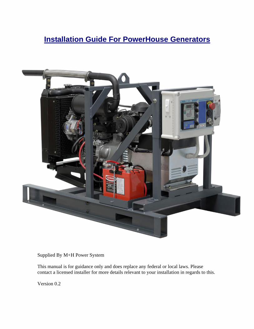
Installation Guide For PowerHouse Generators
DRAFT Not For Release
Supplied By M+H Power System This manual is for guidance only and does replace any federal or local laws. Please contact a licensed installer for more details relevant to your installation in regards to this. Version 0.2
Contents
1. Manuals 2. Wiring Diagram for Controller 3. Visual Inspection 4. Unpacking Crate 5. Exhaust 6. Positioning of Generator 7. Expansion bottle install 8. Fuel System 9. Pre Starting Checks 10. Cranking Battery 11. Controller 12. Starting Generator 13. Servicing Requirements & Parts 14. Generator Do’s and Don’ts 15. Warranty Statement
2

Manuals
Please read and understand and all the manuals and supporting documentation in regards to this generator. Some of these are shown below:
3
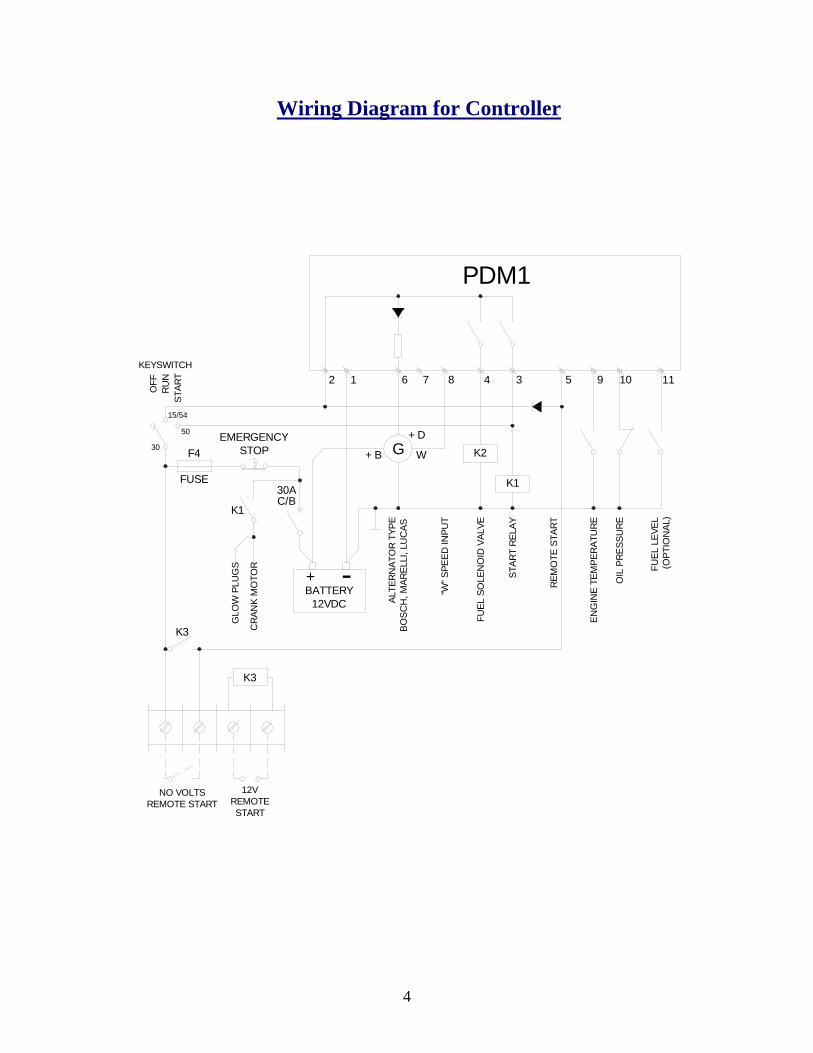
Wiring Diagram for Controller
FUSE
12VDCBATTERY
BO
SCH
, MAR
ELLI
, LU
CAS
ALTE
RN
ATO
R TY
PE
K3
C/B30A
GLO
W P
LUG
S
CR
ANK
MO
TOR -
K3
K1
+
STOPEMERGENCY
F4
50
+ B W
+ D
K1
K2
15/54
30
REM
OTE
STA
RT
ENG
INE
TEM
PER
ATU
RE
OIL
PRE
SSU
RE
(OPT
ION
AL)
FUEL
LEV
EL
KEYSWITCH
OFF
RU
NST
ART 9 11
STAR
T RE
LAY
FUEL
SO
LEN
OID
VAL
VE
"W" S
PEED
INPU
TG
105348762 1
PDM1
NO VOLTSREMOTE START
12VREMOTE START
4
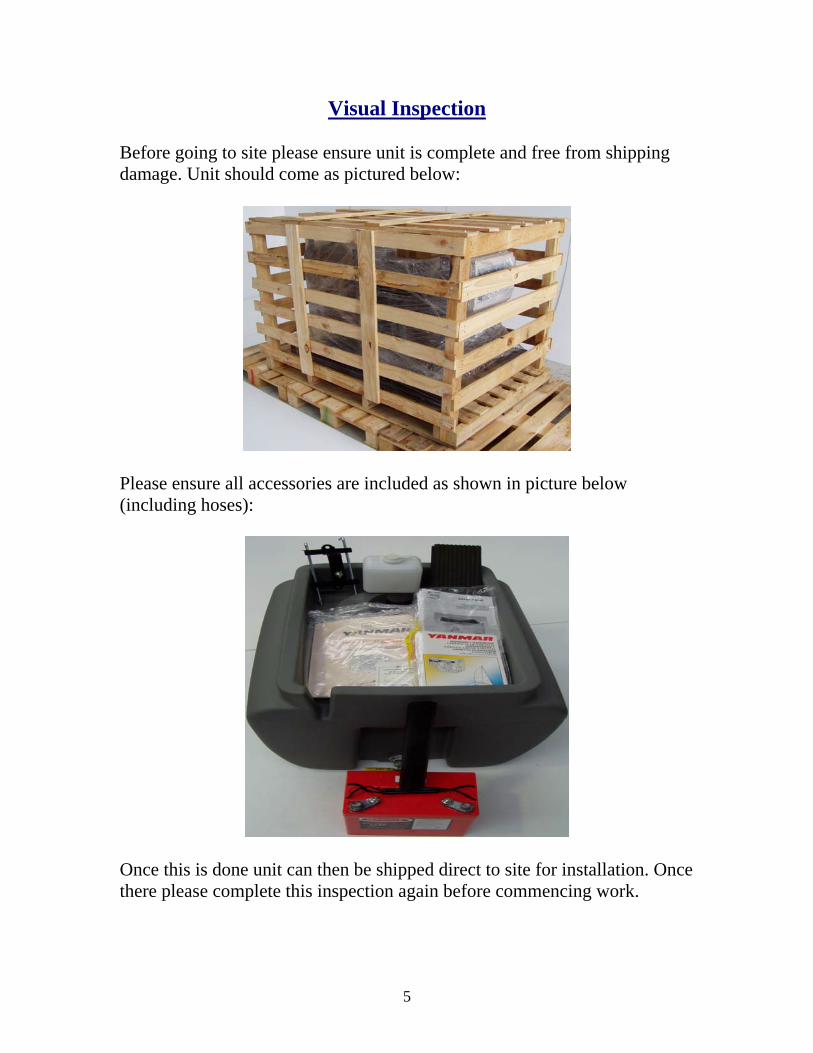
Visual Inspection
Before going to site please ensure unit is complete and free from shipping damage. Unit should come as pictured below:
Please ensure all accessories are included as shown in picture below (including hoses):
Once this is done unit can then be shipped direct to site for installation. Once there please complete this inspection again before commencing work.
5

Unpacking the Crate
Please take care when unpacking generator as not to damage unit and controller. Please note: use suitable size tools and equipment to ensure the unit is not damaged. On completion the unit should look like this or similar.
When removing generator from base please use correct lifting eye or correct lifting pockets to ensure unit is removed safely. Also please give unit a quick visual inspection to ensure no obvious sign of damage to unit.
6
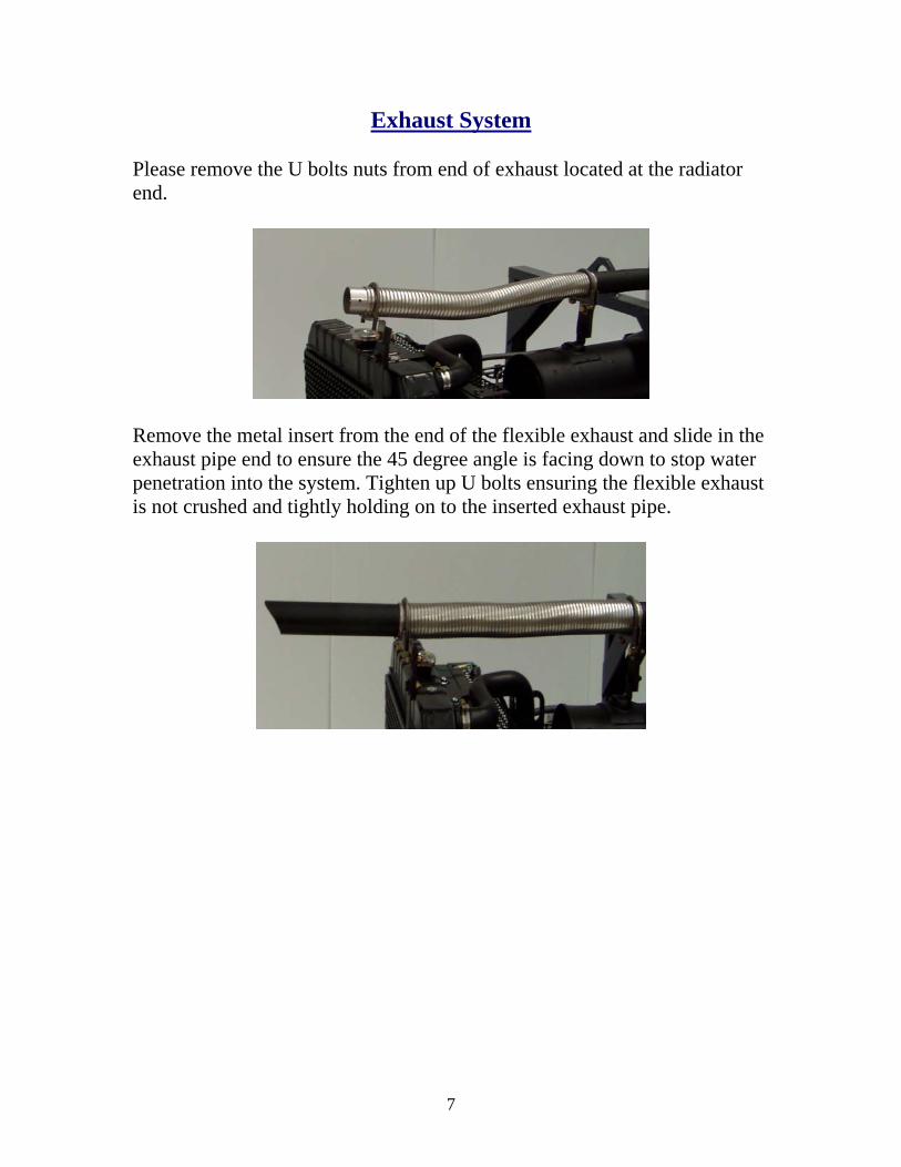
Exhaust System
Please remove the U bolts nuts from end of exhaust located at the radiator end.
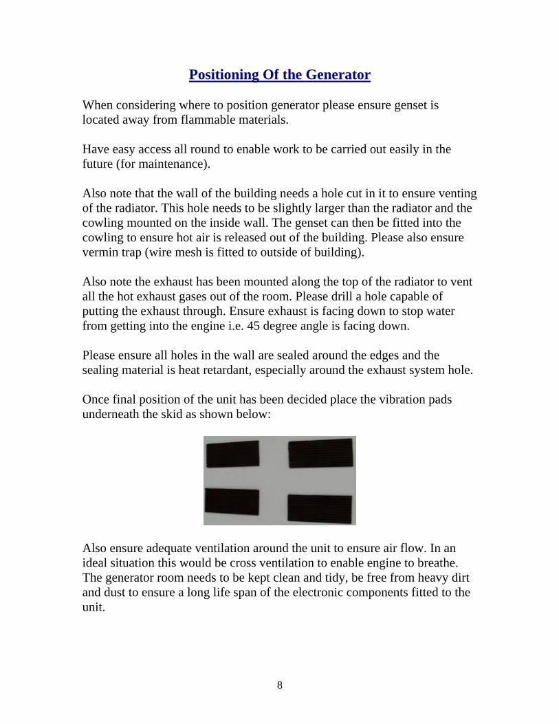
Remove the metal insert from the end of the flexible exhaust and slide in the exhaust pipe end to ensure the 45 degree angle is facing down to stop water penetration into the system. Tighten up U bolts ensuring the flexible exhaust is not crushed and tightly holding on to the inserted exhaust pipe.
7
Positioning Of the Generator
When considering where to position generator please ensure genset is located away from flammable materials. Have easy access all round to enable work to be carried out easily in the future (for maintenance). Also note that the wall of the building needs a hole cut in it to ensure venting of the radiator. This hole needs to be slightly larger than the radiator and the cowling mounted on the inside wall. The genset can then be fitted into the cowling to ensure hot air is released out of the building. Please also ensure vermin trap (wire mesh is fitted to outside of building). Also note the exhaust has been mounted along the top of the radiator to vent all the hot exhaust gases out of the room. Please drill a hole capable of putting the exhaust through. Ensure exhaust is facing down to stop water from getting into the engine i.e. 45 degree angle is facing down. Please ensure all holes in the wall are sealed around the edges and the sealing material is heat retardant, especially around the exhaust system hole. Once final position of the unit has been decided place the vibration pads underneath the skid as shown below:
Also ensure adequate ventilation around the unit to ensure air flow. In an ideal situation this would be cross ventilation to enable engine to breathe. The generator room needs to be kept clean and tidy, be free from heavy dirt and dust to ensure a long life span of the electronic components fitted to the unit.
8

Setting up Water Expansion Bottle Radiator bottle and hose
Fit hose to radiator as below just below cap.
9
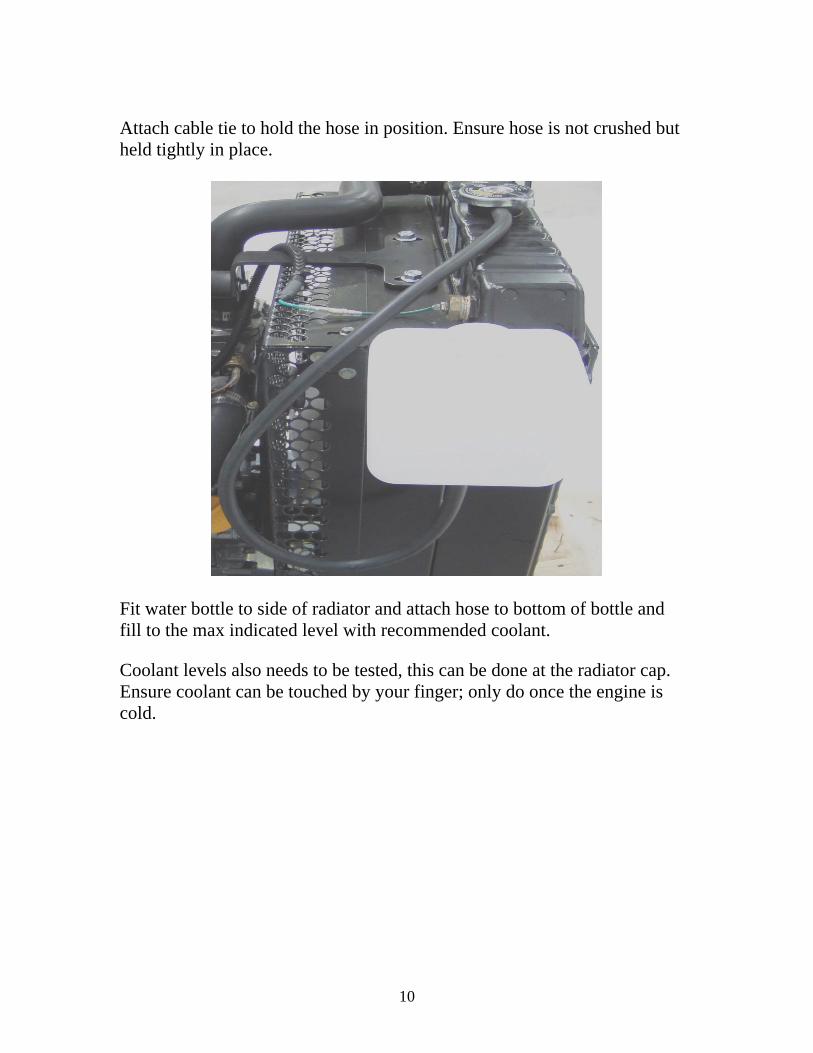
Attach cable tie to hold the hose in position. Ensure hose is not crushed but held tightly in place.
Fit water bottle to side of radiator and attach hose to bottom of bottle and fill to the max indicated level with recommended coolant.
Coolant levels also needs to be tested, this can be done at the radiator cap. Ensure coolant can be touched by your finger; only do once the engine is cold.
10

Fuel System Remove bungs from fuel system located in pictures below prior to commencing any work. (Fuel in Bung)
(Fuel out Bung)
11

Place fuel line hose on bottom of tank. Ensure tap is turned off and clamp is done up tight.
Fit other end of hose to fuel in. On generator located next to radiator and yellow dipstick ensure hose clamp is held tight.
12
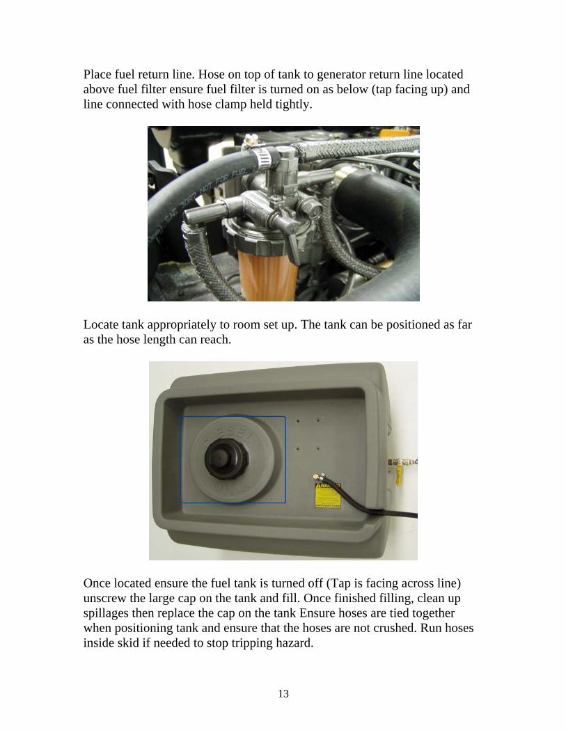
Place fuel return line. Hose on top of tank to generator return line located above fuel filter ensure fuel filter is turned on as below (tap facing up) and line connected with hose clamp held tightly.
Locate tank appropriately to room set up. The tank can be positioned as far as the hose length can reach.
Once located ensure the fuel tank is turned off (Tap is facing across line) unscrew the large cap on the tank and fill. Once finished filling, clean up spillages then replace the cap on the tank Ensure hoses are tied together when positioning tank and ensure that the hoses are not crushed. Run hoses inside skid if needed to stop tripping hazard.
13

Turn fuel tap on. (Tap is facing in line with hose)
Fuel system now needs priming this is done by pushing down on the fuel pump handle on the side of generator. This is located next to the fuel in point next to the dipstick. (Yellow handle bottom left hand corner of picture). Also the system will be a primed once there is sufficient fuel in the fuel filter and the system is pressured. (10 or so depressions)
14
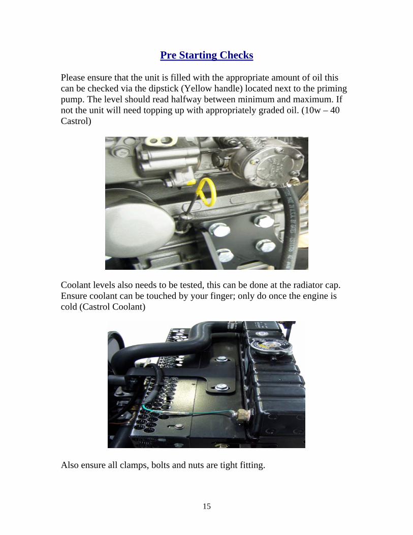
Pre Starting Checks Please ensure that the unit is filled with the appropriate amount of oil this can be checked via the dipstick (Yellow handle) located next to the priming pump. The level should read halfway between minimum and maximum. If not the unit will need topping up with appropriately graded oil. (10w – 40 Castrol)
Coolant levels also needs to be tested, this can be done at the radiator cap. Ensure coolant can be touched by your finger; only do once the engine is cold (Castrol Coolant)
Also ensure all clamps, bolts and nuts are tight fitting.
15
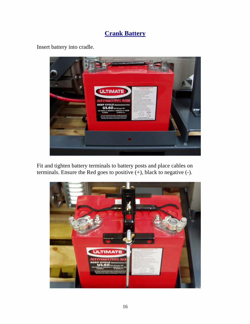
Crank Battery Insert battery into cradle.
Fit and tighten battery terminals to battery posts and place cables on terminals. Ensure the Red goes to positive (+), black to negative (-).
16

Controller
The TEM6- DE controller is one of the most versatile controllers on the market and comes complete with a series of programmable interfaces.
The TEM6-DE (Complete Unit) has been sourced to enable you ease and efficient use of the diesel. It comes complete with a 12v positive output and also a dry contact for use with nearly all inverters out there in the market place (two wire start). Also the unit can be spilt down in many different parts the PDM1 is the engine management component and the TEM 3 is the user interface.
17
TEM 3
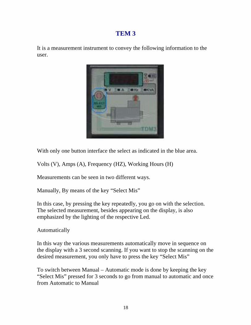
It is a measurement instrument to convey the following information to the user.
With only one button interface the select as indicated in the blue area. Volts (V), Amps (A), Frequency (HZ), Working Hours (H) Measurements can be seen in two different ways. Manually, By means of the key “Select Mis” In this case, by pressing the key repeatedly, you go on with the selection. The selected measurement, besides appearing on the display, is also emphasized by the lighting of the respective Led. Automatically In this way the various measurements automatically move in sequence on the display with a 3 second scanning. If you want to stop the scanning on the desired measurement, you only have to press the key “Select Mis” To switch between Manual – Automatic mode is done by keeping the key “Select Mis” pressed for 3 seconds to go from manual to automatic and once from Automatic to Manual
18

PDM 1
The PDM 1 component of the controller is the engine management part of the system. This will protect the engine from operating outside its normal parameters.
Understanding this controller is very simple by a series off LED’s located across the top line of the controller highlighted below this they are two more just below this. In certain operations these light may be on or off. Ensure you are familiar with these and what they indicate more details can be found below regarding this or in the appropriate manual.
1. Under speed or Over speed engine out off tolerance. Led off in normal running
2. Over temperature. Led off in normal operation 3. Fuel switched off in normal operation 4. Oil low pressure. Led off in normal operation 5. Alternator failure Led 6. Supply LED constantly switched on at power up 7. Glow plug pre heat 8. P1 & P2 programming buttons
19

This controller features are as follows:
• Only one mains supply from 7 to 30 V Dc • Programmable relay into 5 different ways • General Alarm • Glow Plug Pre-Heating • Allows remote Start – Stop • Magnet for stopping • Over speed and low speed survey • Protection from Polarity Reverse • Programmable up to 5 attempts to start • Working temperature range -20 to +60 Degrees
The next part of the controller package is the key switch, audible alarm and also the emergency stop.
The emergency stop is located on the top right hand side of the controller and is the big red button pressing this will cause the generator to stop instantly and will also inhibit the engine to restart while depressed. Once reset the generator will return to normal operation. This should be the first point of call when checking the unit will not start. The buzzer will sound once the unit has gone into fault conditions. The key start is also located just below this part of the unit please refer to the Pre Starting Checks and also the Manual Starting Generator sections before turning the key.
20

Manual Starting Generator
Manual start of the generator can be done by the use of the key switch on front of the unit.
Ensure emergency stop button is out before attempting to start unit. This unit can be started by slowly turning the key slowly through start and then holding in the run position for a few seconds. These may take a few attempts when starting engine for the first time or after long periods of idle times. We recommend this unit gets run for ten minutes every 2 weeks. Also water and oil levels checked as per Pre Starting Checks above in this manual. To stop unit either hit emergency stop button or turn key to off position. If emergency stop button is pressed ensure button is released after unit has stopped.
21
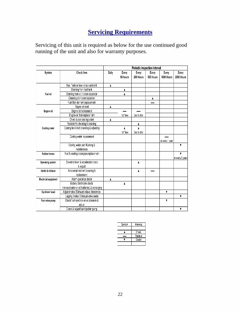
Servicing Requirements
Servicing of this unit is required as below for the use continued good running of the unit and also for warranty purposes.
22
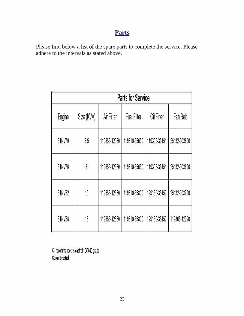
Parts
Please find below a list of the spare parts to complete the service. Please adhere to the intervals as stated above.
23

What to Do and Not to Do
• Keep the generator outside. Never use it indoors. (unless properly installed inside building).
• Install a battery-operated carbon monoxide alarm. • Keep the generator dry. Do not use in wet conditions. To protect from
moisture, operate it on a dry surface and with adequate ventilation. • Dry your hands if wet before touching the generator. • Never try to power the house wiring by plugging the generator into a
wall outlet, a practice known as "backfeeding". This is an extremely dangerous practice that presents an electrocution risk. It also bypasses some of the built-in household circuit protection devices unless done properlly.
• If you must connect the generator to the house wiring to power appliances, get a licensed electrical contractor to do it in accordance with Australian Standards AS/NZS 3000 Electrical Installations.
• Avoid creating a fire hazard. Store fuel for your generator in properly labelled non-glass safety containers, out of the home and away from fuel-burning / heat appliances.
• Before refueling the generator, turn it off and let it cool down. Fuel spilt on hot engine parts could ignite.
• When running generator on hand ensure all load connection devices are removed.
• When performing service work ensure emergency stop button is pressed.
• Do not smoke in or around generator • Do not run generator on light loads for prolonged periods of time, the
generator needs at least 50% loading to prevent damage. • Familise yourself with all paperwork / manuals available to you. • Ensure emergency button is out prior to starting generator.
Contact installer For More Details
24
Warranty and Statement of Guarantee The manufacturer Main Scope of supply Yanmar Engines Sincro generators Heavy duty skid frames with forklift holes and centre lifting frame Generator direct coupled to engine flywheel housing with 6 mounting feet Battery leads and holds down clamps Engine oil, radiator coolant, bolts, industrial paint Main circuit breaker with Clipsal enclosure wired to alternator output terminals Control panel mounted panel frame Anti vibration rubber Fuel tanks Labour and load test Statement of Guarantee The Equipment shall be assembled to ensure satisfactory operation in which continuity of service is the first consideration, and to facilitate inspection, cleaning and repairs. The equipment shall also be built to ensure satisfactory operation under atmospheric conditions prevailing in Australia and local Countries The generating sets shall incorporate every reasonable precaution and provision for the safe working and reliable running of the equipment. The generators shall function without undue vibration. Components, connections and cabling shall be assembled and arranged to minimize the risk of any damage. Consideration needs to be given to the importance of the correct installation of the generating sets and should be done in accordance with the M+H Manual Inherent problems do exist when using machinery, therefore warranty is reliant upon the installer and the operator, reading and understanding the information provided by M+H
25
Warranty Defects liability period shall commence on date of delivery of equipment being, 12 months or first 1000 hours, whichever occurs first. On a warranty claim, equipment will be required for inspection by the Manufacturer or a qualified Power Generation Service Agent, all costs for removal and freight to be covered by Owner The manufacturer will cover parts and labour applicable to scope of supply. [Backed up by the manufacturers warranty for there products]
26