installation instruction s solrif® xl - bimble solar instruction solrif® xl april 27 , ... the...
TRANSCRIPT
bêåëí=pÅÜïÉáòÉê=^dI=jÉí~ääÄ~ì=`eJUVMU=eÉÇáåÖÉå=qÉäÉÑçå=HQN=QQ=TSP=SN=NN=qÉäÉÑ~ñ=HQN=QQ=TSP=SN=NV=áåÑç]ëÅÜïÉáòÉêJãÉí~ääÄ~ìKÅÜ=ïïïKëÅÜïÉáòÉêJãÉí~ääÄ~ìKÅÜ=
sÉêâ~ìÑëÄΩêçë=áåW==_ÉêåI=_áÉäI=_êìÖÖI=`ÜìêI=i~ìë~ååÉI=iìòÉêåI=j∏ÜäáåI=pçäçíÜìêåI=píK=d~ääÉåI=wΩêáÅÜ=
Installation Instructions SOLRIF® XL
Authors: Haller Andreas / Helge Hartwig / Jochen RasmussenDate: April 27, 2006

Installation Instruction SOLRIF® XL
April 27, 2006, Page 2/13
1 Introduction 3
2 Preparing the substructure 3
3 The lower seam 5
4 Wiring 5
5 Clamps in General 5
6 Initial row of clamps 6
7 Lower row of modules 7
8 From the second to the top row of modules 9
9 Top Seam 11
10 Construction Checklist 13
11 Contact 13
Contents

Installation Instruction SOLRIF® XL
April 27, 2006, Page 3/13
1 Introduction
The Installation Instructions SOLRIF®XL describe the process of in-roof installation of
photovoltaic (PV) modules using SOLRIF®XL system frames. The required components,
tips on measuring and precautionary safety measures are discussed in the document
“SOLRIF®XL: Description of the System”. Direct current (DC) wiring is not discussed in
these instructions, for that should only be executed by a professional electrician, unless
prefabricated modules with cables and shock-proof plug and socket connections are being
installed.
2 Preparing the substructure
Remove enough of the existing tiles from the roof so that you have room to spare for the
generator. Room to spare means an extra row all the way around the planned generator
space, which will allow enough space for laying down the flashings. Rafters, laths and roof
deck must be in good condition; if necessary, measures should be taken to put the roof in
good repair. Calculating the dimensions of the generator are discussed in “SOLRIF®XL:
Description of the System”, section 4.2. The lathing in the designated generator area
should be removed.
cáÖK=NW= qáäÉë=~åÇ=ä~íÜáåÖ=ëÜçìäÇ=ÄÉ=êÉãçîÉÇ=Ñêçã=íÜÉ=ÇÉëáÖå~íÉÇ=ÖÉåÉê~íçê=ëé~ÅÉK
As is the case with a conventional tile roof, with SOLRIF®XL modules laths serve as the
substructure. Properly dried softwoods in accordance with DIN 1052 should be used for the
laths. The length of the lathing should be at least as long as the generator width including
the profiles (see “SOLRIF®XL:System Description”, section 4.2) and should be placed
flush against the rafters, eventually using spacers. Because of the weight, the lathing for
SOLRIF®XL should always be supported by counter lathing or rafters at both ends.
beabsichtigte Generatoroberfläche
Designated generator surface area

Installation Instruction SOLRIF® XL
April 27, 2006, Page 4/13
cáÖK=OW= qÜÉ=É~îÉë=~åÇ=pliofc∆ui=ãçÇìäÉ=ä~íÜáåÖ=áë=Ñ~ëíÉåÉÇ=íç=íÜÉ=ÅçìåíÉê=ä~íÜáåÖ=çê=ê~ÑíÉêë=áå=~ÅÅçêÇ~åÅÉ=ïáíÜ=íÜÉ=ä~íÜáåÖ=éä~åK=
The eaves lath is fastened by screws 5 cm above the first single-piece tiling lath located
below the generator area. The eaves lath will be needed as a surface for the Wakaflex
tape (see Detailed Drawing A, page 7). Care should be taken to ensure horizontal
installation. The lath should sit flush against the rafters or the spacers.
The first SOLRIF®XL module lath is now fastened flush above the eaves lath. The median
line of this lath is important to the worker overseeing the installation of the system as a
base line. All further laths are placed in reference to this base line, corresponding to the
vertical grid, which is discussed in “SOLRIF®XL: Description of the System”, section 4.1.
mä~å=NW=i~íÜáåÖ=éä~å=
=
R_ver
R_ver
R_ver
50 mm
Installation Instruction SOLRIF® XL
April 27, 2006, Page 5/13
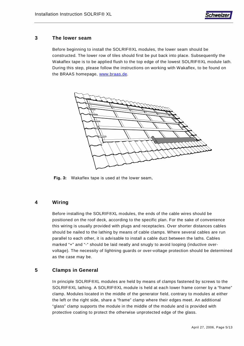
3 The lower seam
Before beginning to install the SOLRIF®XL modules, the lower seam should be
constructed. The lower row of tiles should first be put back into place. Subsequently the
Wakaflex tape is to be applied flush to the top edge of the lowest SOLRIF®XL module lath.
During this step, please follow the instructions on working with Wakaflex, to be found on
the BRAAS homepage, www.braas.de.
cáÖK=PW= t~â~ÑäÉñ=í~éÉ=áë=ìëÉÇ=~í=íÜÉ=äçïÉê=ëÉ~ãKKKK
4 Wiring
Before installing the SOLRIF®XL modules, the ends of the cable wires should be
positioned on the roof deck, according to the specific plan. For the sake of convenience
this wiring is usually provided with plugs and receptacles. Over shorter distances cables
should be nailed to the lathing by means of cable clamps. Where several cables are run
parallel to each other, it is advisable to install a cable duct between the laths. Cables
marked “+” and “-“ should be laid neatly and snugly to avoid looping (inductive over-
voltage). The necessity of lightning guards or over-voltage protection should be determined
as the case may be.
5 Clamps in General
In principle SOLRIF®XL modules are held by means of clamps fastened by screws to the
SOLRIF®XL lathing. A SOLRIF®XL module is held at each lower frame corner by a “frame”
clamp. Modules located in the middle of the generator field, contrary to modules at either
the left or the right side, share a “frame” clamp where their edges meet. An additional
“glass” clamp supports the module in the middle of the module and is provided with
protective coating to protect the otherwise unprotected edge of the glass.

Installation Instruction SOLRIF® XL
April 27, 2006, Page 6/13
The positioning of the clamps is determined by the grid plan – see the document
“SOLRIF®XL: System Description”, section 4.3.
Tip: Ensure that the screws are positioned at least 22.5 mm from the lower and 45
mm from the upper lath edge (DIN 1052-2).
6 Initial row of clamps
During installation begin with the lower row of “frame” clamps, which are screwed directly
through the Wakaflex tape along the longitudinal axis of the lower SOLRIF®XL module
lath. The grid uses the clamp’s lower bore as its point of reference. Each clamp will require
two 4.5 x 30 mm SPAX-S A2-steel sheet-metal screws.
cáÖK=QW= qÜÉ=Ñáêëí=êçï=çÑ=Åä~ãéë=áë=ëÅêÉïÉÇ=ìéçå=íÜÉ=t~â~ÑäÉñ=í~éÉK=qÜÉ=pÉ~äáåÖ=í~éÉ=
âÉÉéë=ëã~ää=~åáã~äë=Ñêçã=íÜÉ=Üçääçïë=EëÉÉ=aÉí~áä=aê~ïáåÖ=^I=é~ÖÉ=TFK=
Tip: Mark the longitudinal axis of the module lath on the Wakaflex tape with a
chalked string. Then mark the horizontal clamps’ position in accordance with
the grid. The clamps are then fixed in their exact position by inserting a
screw through the lower bore at the “line cross”. Now the additional “glass”
clamps are put into place.
Finally sealing tape is applied flush to the upper edge of the module lath. This will
prevent small animals from entering the hollows.
A

Installation Instruction SOLRIF® XL
April 27, 2006, Page 7/13
aÉí~áä=aê~ïáåÖ=^W=îÉêíáÅ~ä=Åêçëë=ëÉÅíáçå=çÑ=íÜÉ=äçïÉê=ëÉ~äáåÖ=~êÉ~==
7 Lower row of modules
Over-lapping determines the order in which the SOLRIF®XL modules are installed, thus
each row is laid from right to left. As with roof tiles, the module rows are laid from the
bottom up.
cáÖK=RW= pí~êíáåÖ=~í=íÜÉ=êáÖÜíI=íÜÉ=Ñáêëí=êçï=çÑ=ãçÇìäÉë=áë=ä~áÇK=
Verlegerichtung
B
Seitenblech rechts
50 mm
R_ver
Wakaflexband
Kehldichtband
oáÖÜí=ëáÇÉJëÜÉÉí=
i~óáåÖ=ÇáêÉÅíáçåi~óáåÖ=ÇáêÉÅíáçåi~óáåÖ=ÇáêÉÅíáçåi~óáåÖ=ÇáêÉÅíáçå==

Installation Instruction SOLRIF® XL
April 27, 2006, Page 8/13
aÉí~áä=aê~ïáåÖ=_W==pÉèìÉåÅÉ=Ñêçã=íÜÉ=ëáÇÉJëÜÉÉí=íç=íÜÉ=Ñáêëí=ãçÇìäÉ=
=Before the first SOLRIF module can be fitted into the clamp, the right side-sheet must be
installed (step 1). Then a right-side joining profile is inserted into the outermost clamp
(steps 2 + 3). The first module can now be installed (steps 4 + 5).
cáÖK=SW= qÜÉ=ãçÇìäÉë=çÑ=íÜÉ=Ñáêëí=êçïI=ëáÇÉJëÜÉÉíë=~åÇ=àçáåáåÖ=éêçÑáäÉë=~êÉ=áåëí~ääÉÇK=
=
C
D
Seitenblech links
1.
2.
3.
4.5.
äÉÑí=ëáÇÉäÉÑí=ëáÇÉäÉÑí=ëáÇÉäÉÑí=ëáÇÉJJJJëÜÉÉíëÜÉÉíëÜÉÉíëÜÉÉí==

Installation Instruction SOLRIF® XL
April 27, 2006, Page 9/13
aÉí~áä=aê~ïáåÖ=`W=pÉèìÉåÅÉ=Ñçê=ä~óáåÖ=íÜÉ=
ãáÇÇäÉ=ãçÇìäÉë=
The next SOLRIF®XL modules in the first
row are laid following the steps shown in
Detail Drawing C. The modules should be
wired according to the cord plan before
they are laid.
aÉí~áä=aê~ïáåÖ=aW=pÉèìÉåÅÉ=çå=íÜÉ=äÉÑíJ
ëáÇÉJëÜÉÉí=
After the last SOLRIF®XL module in the
row has been laid, the left side-sheet and
the joining profile can be set. (Detail D)
8 From the second to the top row of modules
After the first row of SOLRIF®XL modules has been laid complete with the joining profiles,
the clamps for the second row can be set. It is possible by using the grid plan to pre-mark
the clamp position on the module lathing and precisely to set the clamps in turn.
2.
1.
3.
1.
2.
4.5.
3.

Installation Instruction SOLRIF® XL
April 27, 2006, Page 10/13
Usually, however, a different, easier method is used:
The “frame” clamps are positioned by eye plumb, using the clamps in the first row as a
guide. The sides of the framing profiles of the lower SOLRIF®XL modules can help in
alignment.
cáÖK=TW=i~óáåÖ=íÜÉ=åÉñí=êçï=çÑ=ãçÇìäÉëK=
=
aÉí~áä=aê~ïáåÖ=bW=lîÉêä~ééáåÖ=ãçÇìäÉë=
The clamps are fastened leaving 15
mm space to the previous row of
modules. This space will allow the
replacement of individual modules
within the generator field by a
simple slide-and-slip maneuver.
Tip: Use a 15 mm spacing wood to
place the clamps.
The same procedure is to be used
for the “glass” clamps, which again
are set at regular intervals.
ESeitenblech links
oberes Seitenblech rechts
R_ver
R_ver
15 mm
rééÉê=êáÖÜí=ëáÇÉrééÉê=êáÖÜí=ëáÇÉrééÉê=êáÖÜí=ëáÇÉrééÉê=êáÖÜí=ëáÇÉJJJJëÜÉÉíëÜÉÉíëÜÉÉíëÜÉÉí=
äÉÑí=ëáÇÉäÉÑí=ëáÇÉäÉÑí=ëáÇÉäÉÑí=ëáÇÉJJJJëÜÉÉíëÜÉÉíëÜÉÉíëÜÉÉí=

Installation Instruction SOLRIF® XL
April 27, 2006, Page 11/13
aÉí~áä=aê~ïáåÖ=cW=oìÄÄÉê=ëíêáé==
In order to guard against seeping
water a rubber strip is inserted into
the upper framing profile. It is
advisable to cut the rubber strip at
the side with a carpet knife so that
the strip can be laid so as to ensure
a safeguard against rainwater.
To lay the remaining rows of modules, side-sheets and joining profiles, follow the
procedure outlined in section 1.5.
Upper side-sheets
The upper side-sheets are somewhat longer than usual side-sheets in order to allow
backing water to run off. The installation procedure is similar to that of normal side profiles.
Top Clamps
The top row of modules are secured on the upper edge by “frame” clamps which later
accommodate the flashing. Their placement is determined by the grid plan.
9 Top Seam
The top seam sheets are set into clamps instead of a further row of modules. This will be
the crossover to the roof tiles.
GummilippeêìÄÄÉê=ëíêáéêìÄÄÉê=ëíêáéêìÄÄÉê=ëíêáéêìÄÄÉê=ëíêáé

Installation Instruction SOLRIF® XL
April 27, 2006, Page 12/13
cáÖK=UW= i~óáåÖ=íÜÉ=êáÇÖÉ=ëÜÉÉíë=
Start with the right-hand side ridge sheet, which, because of its special form, fits exactly
into the upper right-hand side-sheet. Then the middle ridge sheets are installed, lipped
edge against lipped edge.
The left-hand side ridge sheet has been specially formed as well and fits into the upper
left-hand side-sheet. The adjacent sheet-lips are joined watertight by means of the edge-
safeguard profile.
cáÖK=VW= i~óáåÖ=íÜÉ=êççÑ=íáäÉëK=
=
The missing tiles are re-laid at the sides of and above the generator field. If necessary, the
tiles may have to be cut in order to provide for a proper integration of the generator into the
roof. Professional roofing skills are required for this last step, too.
oberes Seitenblech linksFirstblech
mittleres Firstblech rééÉê=äÉÑí=ëáÇÉJëÜÉÉí jáÇÇäÉ=êáÇÖÉJëÜÉÉí oáÇÖÉJëÜÉÉí=

Installation Instruction SOLRIF® XL
April 27, 2006, Page 13/13
10 Construction Checklist
Pos. Article Quantity (piece; meter) Supplier
1 Grid plan 1 SOLRIF supplier
2 Framed modules dependent upon Pos. 1 SOLRIF supplier
3 Clamps, spring steel dependent upon Pos. 1 SOLRIF supplier
4 4.5 x 30 mm SPAX-S sheet-
metal A2-steel screws
2 per clamp Installer
5 SOLRIF lathing 30 x 100 mm,
30 x 50 mm doubled
Area width x (number of
module rows + 1)
Installer
6 Eaves lath 40 x 45 or 30 mm 1 x width of area Installer
7 SPAX-S with countersunk
heads for lathing 6 x 90 mm
dependent upon area size
and grid rafters and laths
Installer
8 Sealing tape 30 x 40 mm 1 x width of area Installer
9 Joining profile, aluminium 1 pair per module row SOLRIF supplier
10 Side-sheets 1 pair per module row - 1 Local roof plumber
11 Side-sheets, top 1 pair Local roof plumber
12 Upper side-sheets / middle No. of module columns - 2 Local roof plumber
13 Upper side-sheets / right 1 Local roof plumber
14 Upper side-sheets / left 1 Local roof plumber
15 Wakaflex tape 1 x width of area Installer
16 Cable ties due to generator size Installer
17 Measuring tape and meter stick 1 a piece Installer
18 Carpenter’s pencil 2 Installer
19 Handsaw and jigsaw 1 a piece Installer
20 Screwdriver (bit tip holder 2) 1 Installer
21 Knife 1 Installer
22 Chalked string 1 Installer
23 Metal shears, sheet-metal
pliers
1 a piece Installer
11 Contact
Andreas Haller Helge Hartwig, Dr.
Solar Energy Department PV-mounting systems
Ernst Schweizer AG, Metallbau
Bahnhofplatz 11, CH-8908 Hedingen
Phone direct +41 44 763 63 80 +41 44 763 63 40
Fax +41 44 763 64 10
www.schweizer-metallbau.ch
www.solrif.com