installation instructions - roushperformance.com · 1/4” and 3/8” drive ratchets with...
TRANSCRIPT

OFF ROAD USE ONLY – NOT FOR USE WITH POLLUTION CONTROLLED VEHICLES
1305SS-TVSP1UGIM-BA Page 1 of 12 1-800-59-ROUSH
2005-09 R2300 Phase 1 to 2 Kit (Single Sheave) P/N: 1305SS-TVSP1UG
NOT FOR USE WITH POLLUTION CONTROLLED VEHICLES
Installation Instructions
Applications:
2005-09 Ford Mustang GT (w/ Manual Transmissions ONLY) with the 2005-09 TVS Phase1 Kit (1305SS-TVSP1-AA) already installed on the vehicle.
Important Notes:
Before upgrading your Mustang ROUSHCharger Kit, please read the installation manual andverify that all items are present. Contact ROUSH Customer Service at 1-800-59-ROUSH,9:00 AM to 5:00 PM weekdays, for any questions regarding fit or instructions that are unclearto you.
Premium fuel (91 octane or higher) is required to prevent “spark-knock” or detonation undercertain operating conditions.
The use of fuel additives (ie. octane boosters) is not recommended. These chemicals candamage your engine and cause drivability issues with your vehicle.
Operating your engine without the Roush PCM recalibration will result in engine damage orfailure.

OFF ROAD USE ONLY – NOT FOR USE WITH POLLUTION CONTROLLED VEHICLES
1305SS-TVSP1UGIM-BA Page 2 of 12 1-800-59-ROUSH
PACKAGING LIST FOR COMPLETE ROUSHCHARGER KIT
Description RPP Part Number Qty
Phase 2 Upgrade Hardware
Pulley – S/C Bolt-On (6K x 80mm) 6K80-6V066 1
FEAD Belt – 6K Aramid Cord R07020062-13-AA 1
Go to Website - Installation Instructions one pager 1315-P1INST 1
Ford Racing 2010 Fuel System Upgrade Kit M-9407-MSVTA 1
Nut – Fuel Pump Driver Module Mounting (M6) W520412 2
Description RPP Part Number Qty
CALKIT 1305-P2CALKIT 1
Optional Roush PCM Flash PCM-FLASHDOC 1
Flash Voucher Card P1305-P2 1

OFF ROAD USE ONLY – NOT FOR USE WITH POLLUTION CONTROLLED VEHICLES
1305SS-TVSP1UGIM-BA Page 3 of 12 1-800-59-ROUSH
EQUIPMENT AND SUPPLIES REQUIRED
1/4” and 3/8” Drive Ratchets with Extensions
Metric and Standard Socket Sets (short and deep recommended)
1/2” Drive Ratchet or Breaker Bar
Metric and Standard Wrench Sets
3/8” Drive Torque Wrench (7-35 ft-lb range)
Short Phillips-head Screwdriver
5/8” Fuel Line Removal Tool
T-20 Torx Bit Screwdriver or Socket
5/16” Drill Bits and Drill motor
Coolant (meeting G-05 specification)
6” Scale, Tape Measure, or Other Measuring Device
Assembly Lubricant (White Lithium Grease or Petroleum Jelly)
Electrical Tape
Sharp Knife or Razor Blade
Tie Straps (Zip Ties)
Trim Pad Tool (for pushpin removal)
Fender Cover (2)
Medium Strength Thread Locker – Loctite 242 (blue) or equivalent

OFF ROAD USE ONLY – NOT FOR USE WITH POLLUTION CONTROLLED VEHICLES
1305SS-TVSP1UGIM-BA Page 4 of 12 1-800-59-ROUSH
GLOSSARY OF TERMS
ACT Air Charge Temperature Sensor (From the factory, this function is integrated into the MAF sensor. With this kit, a separate ACT sensor is installed into the intake manifold)
CMCV Charge Motion Control Valve (Located on the back of the base intake manifold. This feature is not used with the Roushcharger)
ETC Electronic Throttle Control
IPTS Injection Pressure and Temperature Sensor
MAFS Mass Air Flow Sensor
PCM Powertrain Control Module (a.k.a. ECM, ECU, PCU, EEC)
PCV Positive Crankcase Ventilation
RDT ROUSH Diagnostic Tool
TPS Throttle Position Sensor
VMV Vapor Management Valve (Located on driver side strut tower)
Breakout Point A place in an electrical harness where the wiring for an individual component leaves (breaks out of) the main harness to attach to an individual component.
INFORMATION ABOUT THE SUPERCHARGER BYPASS OPERATION
There is a great deal of misinformation about the function of supercharger bypass systems. The supercharger is a positive-displacement pump; that is, so long as it is rotating, it is always pumping air. During low demand or high vacuum operation (i.e. idle, deceleration, and light throttle cruise), the pumping action is undesirable as it creates unwanted heat and noise. The bypass circuit, when open, prevents any pressure buildup across the supercharger and allows air to circulate through the rotors, allowing the supercharger to “idle” freely during these conditions. This results in reduced noise, and by reducing heat buildup in the intake, significantly improves street and strip performance. As throttle demand increases, the bypass circuit is closed, resulting in full performance from the supercharger. The bypass circuit is never used to limit or control boost during full-throttle operation and defeating or altering the bypass function will not result in improved performance in any condition, and will result in poor drivability.

OFF ROAD USE ONLY – NOT FOR USE WITH POLLUTION CONTROLLED VEHICLES
1305SS-TVSP1UGIM-BA Page 5 of 12 1-800-59-ROUSH
LIMIT OF LIABILITY STATEMENT
The information contained in this publication was accurate and in effect at the time the publication was approved for printing and is subject to change without notice or liability. Roush Performance Products (RPP) reserves the right to revise the information presented herein or to discontinue the production of parts described at any time.
SAFETY PRECAUTIONS
STOP! CAREFULLY READ THE IMPORTANT SAFETY PRECAUTIONS AND WARNINGS
BEFORE PROCEEDING WITH THE INSTALLATION!
Appropriate disassembly, assembly methods and procedures are essential to ensure the personal safety of the individual performing the kit installation. Improper installation due to the failure to correctly follow these instructions could cause personal injury or death. Read each step of the installation manual carefully before starting the installation.
Always wear safety glasses for eye protection.
Place the ignition switch in the OFF position.
Always apply the parking brake when working on the vehicle.
Block the front and rear tire surfaces to prevent unexpected vehicle movement.
If working without a lift, always consult vehicle manual for correct lifting
specifications.
Operate the engine only in well-ventilated areas to avoid exposure to carbon monoxide.
Do not smoke or use flammable items near or around the fuel system.
Use chemicals and cleaners only in well-ventilated areas.
Batteries can produce explosive hydrogen gas which can cause personal injury. Do not
allow flames, sparks or flammable sources to come near the battery.
Keep hands and any other objects away from the radiator fan blades.
Keep yourself and your clothing away from moving parts when the engine is running.
Do not wear loose clothing or jewelry that can be caught in rotating or moving parts.
Allow the engine, cooling system, brakes and exhaust to cool before working on a
vehicle.

OFF ROAD USE ONLY – NOT FOR USE WITH POLLUTION CONTROLLED VEHICLES
1305SS-TVSP1UGIM-BA Page 6 of 12 1-800-59-ROUSH
1. Cover both fenders with fender covers to protect the vehicle finish.
2. Release the fuel system pressure (NOTE: The following procedure is taken directly from the FordService Manual).
WARNING: Fuel in the fuel system remains under high pressure even
when the engine is not running. Before working on or disconnecting any of the fuel lines or fuel system components, the fuel system pressure must be relieved. Failure to do so can result in personal injury.
WARNING: Do not smoke or carry lighted tobacco or open flame of
any type when working on or near any fuel-related components. Highly flammable mixtures are always present and can be ignited, resulting in personal injury.
a. Remove the fuel pump module fuse.NOTE: The fuel pump module fuse is located in the underhood fuse box, location 13.
b. Start the engine and allow it to idle until it stalls.
c. After the engine stalls, crank the engine for approximately 10 seconds to make sure thefuel injector supply manifold pressure has been released.

OFF ROAD USE ONLY – NOT FOR USE WITH POLLUTION CONTROLLED VEHICLES
1305SS-TVSP1UGIM-BA Page 7 of 12 1-800-59-ROUSH
d. Turn the ignition switch to the OFF position.
e. Reinstall the fuse that was removed in step a.
3. Using an 8mm wrench, disconnect the (-) negative & (+) positive connections to the battery.
Before continuing, refer to the CALKIT included with your ROUSHcharger kit. Determine the PCM flash method you will be using. If performing the PCM flash yourself or at a preferred ROUSH dealer, proceed to step 5. If sending the PCM to ROUSH for a ROUSH performed PCM flash, continue with step 4.
4. Disconnect the 3 PCM (Powertrain Control Module) connectors by lifting the grey levers over theconnector back shell and lifting the connectors from their sockets. Remove the PCM by removingtwo 10mm bolts and pulling the PCM forward and lifting out of the engine compartment. Followthe instructions on the next page as soon as possible to help minimize the amount of time youare without a PCM.
Important: Be sure to write your VIN number and phone number (in case we need to contact you for additional vehicle information) on the PCM using a permanent marker.
Connector
Locations
Retaining Bolts

OFF ROAD USE ONLY – NOT FOR USE WITH POLLUTION CONTROLLED VEHICLES
1305SS-TVSP1UGIM-BA Page 8 of 12 1-800-59-ROUSH
INSTRUCTIONS FOR RETURNING THE PCM TO ROUSH FOR CALIBRATION
Outlined below are the instructions for returning your stock powertrain control module (PCM) to Roush Performance Products so we can install our calibration to make the engine run properly with the new components. Please complete the “Optional Roush PCM Flash” request document and include it, along with the PCM, and the “Voucher Card”. Once we receive your PCM, we will reprogram and return it back to you the same day for next-day delivery. Operating your engine without our calibration will result in engine damage or failure and will void all warranty.
Note: It is important to reinstall the PCM in the vehicle it came from to prevent setting a trouble code and having to relearn the anti-theft code which can only be performed using specialized Ford Service Bay tools.
If you haven’t already done so, write your vehicle identification number (VIN) and phone numberon the PCM using a permanent marker.
Using bubble wrap, or another appropriate packing material, wrap and package the PCM to helpprevent it from being damaged during shipping.
Place the wrapped PCM in an appropriate shipping box.
Complete the “Optional ROUSH PCM Flash” request document (PCM-FLASHDOC) andattach the flash “Voucher Card” (P1305-P2CALKIT) to the document.
Include the “Optional ROUSH PCM Flash” document and the “Voucher Card” in theshipping box, along with the PCM.
Ship the PCM and contents to:
ATTN: PCM FLASH 39555 Schoolcraft Rd Plymouth, MI 48170
Upon receipt of the PCM, a customer service representative will contact you to arrange payment. Once you receive your ROUSH flashed PCM, reverse step 4 for PCM installation.

OFF ROAD USE ONLY – NOT FOR USE WITH POLLUTION CONTROLLED VEHICLES
1305SS-TVSP1UGIM-BA Page 9 of 12 1-800-59-ROUSH
5. Remove the “Phase 1” FEAD belt and supercharger pulley.
6. Install the new S/C Pulley (6K80-6V066) onto the supercharger using the six (6) N605771 bolts(M6 x 14) which were removed in the previous step. Ensure that the pulley is properly seated onthe hub before tightening any bolts. Add medium strength threadlocker to the bolts and tighten ina criss-cross pattern. Final torque the bolts to 8-12 Nm.
7. Install the new FEAD belt (R07020062) as shown. Using a ½ inch drive breaker bar or ratchet,rotate the belt tensioner clockwise and install the belt.
8. Using the Ford Racing installation manual “M-9407-GT05” which is located at the end of thismanual in Appendix A, install the Ford Racing GT500 Fuel System Upgrade Kit (R14020001).These instructions can also be found on the internet at:www.fordracingparts.com/download/instructionsheets/FordInstShtM-9407-GT05.pdf
9. Use (2) M6 nuts (W520412) to secure the new fuel pump driver module to an existing stud in thetrunk as per the Ford installation manual.
10. Inspect all under-hood wiring harnesses for potential interference issues. Use zip ties to safelyposition the harness away from any areas of concern.
11. If the PCM was removed and shipped to ROUSH for a ROUSH performed flash reinstall thePCM, once it is returned from ROUSH, by reversing removal steps on page 8. If you areequipped with a SAE J2534 pass through device, refer to the PCM Flashing section wheninstallation is complete. DO NOT ATTEMPT TO REINSTALL THE PCM AND START THEVEHICLE IF THE PCM IS NOT EQUIPPED WITH A ROUSH CALIBRATION. OPERATING THEENGINE WITHOUT THE RECALIBRATED PCM WILL RESULT IN ENGINE DAMAGE ORFAILURE AND WILL VOID THE WARRANTY.

OFF ROAD USE ONLY – NOT FOR USE WITH POLLUTION CONTROLLED VEHICLES
1305SS-TVSP1UGIM-BA Page 10 of 12 1-800-59-ROUSH
12. Start the vehicle and check for fluid leaks, unusual noises, dash service lights, and unusualoperation. If problems are detected, immediately stop the engine or vehicle, diagnose and repairthe problem. If you have any questions or concerns please call 1-800-59-ROUSH.
PCM FLASHING
1. If equipped with a SAE J2534 pass through device, refer to the RDT-CALIM manual found online at rdt.roush.com on the home page for instructions on PCM flashing. The RDT-CALIM manual will guide you through the ROUSH Diagnostic Tool (RDT) software installation process and the ROUSH PCM flashing procedure. OPERATING THE ENGINE WITHOUT THE RECALIBRATED PCM WILL RESULT IN ENGINE DAMAGE OR FAILURE AND WILL VOID THE WARRANTY.
2. Once the PCM has been successfully re-calibrated, start the engine and check for unusual noises, dash service lights, and unusual operation. If problems are detected, immediately stop the engine or vehicle, diagnose and repair the problem.

OFF ROAD USE ONLY – NOT FOR USE WITH POLLUTION CONTROLLED VEHICLES
1305SS-TVSP1UGIM-BA Page 11 of 12 1-800-59-ROUSH
WARRANTY
All retail parts carry a 90-day warranty from the date of purchase. This warranty covers defects in materials or workmanship, and does not include (i) normal wear and tear, environmental conditions, improper installation; (ii) road hazards, misuse, abuse, neglect, accidents, collision, fire, theft, freezing, vandalism, riot, explosion, or objects striking the vehicle; (iii) misusing the vehicle, such as driving over curbs, overloading, racing, or using the vehicle as a stationary power source; (iv) altering, disassembling or modifying the parts; (v) defects caused or induced by failures, breakdowns, or damage by other parts, components or the vehicle; (vi) subjecting the parts to excessive moisture or water or any motor vehicle fluids (e.g.: oil, anti-freeze, battery acid, brake fluid, etc.); (vii) acts of God, natural disasters and other similar causes beyond the reasonable control of Roush; or (viii) application of chemicals that affect the parts. This Limited Warranty does not cover surface deterioration of paint, trim, and appearance items that result from use and/or exposure to the elements, such as stone chips, scratches, bird droppings, lightning, hail, windstorm, dings, dents, earthquake, road salt, tree sap, water or flood.
ROUSH SHALL NOT BE LIABLE TO REIMBURSE CUSTOMER/DEALER FOR INCIDENTAL OR CONSEQUENTIAL DAMAGES RESULTING FROM THE INSTALLATION OR USE OF ANY PRODUCT SOLD THROUGH THIS CATALOG OR ARISING OUT OF ANY BREACH OF WARRANTY. EXCEPT AS MAY BE STATED IN THIS CATALOG, ROUSH DISCLAIMS ALL EXPRESS AND IMPLIED WARRANTIES, INCLUDING THE WARRANTIES OF MERCHANTABILITY AND FITNESS FOR A PARTICULAR PURPOSE. IN NO EVENT SHALL ROUSH’S LIABILITY EXCEED THE PRICE PAID BY CUSTOMER/DEALER FOR PRODUCTS SOLD REGARDLESS IF ROUSH HAS BEEN ADVISED IN ADVANCE OF ANY POTENTIAL PROBLEM OR IF A CLAIM IS BASED ON CONTRACT, TORT, STRICT LIABILITY, PRODUCT LIABILITY OR OTHERWISE. SOME STATES DO NOT ALLOW THE EXCLUSION OR LIMITATION OF IMPLIED WARRANTIES OR THEIR DURATION, OR LIABILITY FOR INCIDENTAL OR CONSEQUENTIAL DAMAGES, SO THE ABOVE EXCLUSIONS OR LIMITATIONS MAY NOT APPLY.
This Roush Supercharger kit is designed and tested to function properly only on vehicles as they are equipped from the factory (completely stock powertrain). The use of aftermarket parts and equipment such as: cams, headers, nitrous oxide systems, other bolt-on performance parts, or any other performance parts not sold by, manufactured by, or approved of in writing by Roush, will result in powertrain and supercharger kit damage and will not be the responsibility of Roush in any way.
If you have any questions or concerns please call 1-800-59-ROUSH.

OFF ROAD USE ONLY – NOT FOR USE WITH POLLUTION CONTROLLED VEHICLES
1305SS-TVSP1UGIM-BA Page 12 of 12 1-800-59-ROUSH
APPENDIX A
Ford Racing GT500 Fuel System Upgrade Installation Instructions

M-9407-GT05 Mustang GT Dual Fuel Pump Kit INSTRUCTION SHEET
NO PART OF THIS DOCUMENT MAY BE REPRODUCED WITHOUT PRIOR AGREEMENT AND WRITTEN PERMISSION OF FORD RACING PERFORMANCE PARTS
Please contact the Techline for the most current instruction information (800) FORD788
! ! ! PLEASE READ THE FOLLOWING INSTRUCTIONS CAREFULLY PRIOR TO INSTALLATION ! ! !
OVERVIEW: The following information describes the procedure for the installation of the M-9407-GT05 dual fuel pump kit into 2005-07 Mustang GT. STEP 1: Release fuel system pressure.
1A: The fuel pump relay can be found in the bussed electrical center. The fuel pump relay is located in position 21 as shown in the inside cover of the bussed electrical center. Remove the fuel pump relay (see Fig. 1).
Techline (800) FORD788
Factory Ford shop manuals are available from Helm Publications, 1-800-782-4356
IS-1850-0129 Page 1 of 15
! ! ! WARNING: DO NOT SMOKE OR CARRY LIGHTED TOBACCO OR OPEN FLAME OF ANY TYPE WHEN WORKING ON OR NEAR ANY FUEL-RELATED COMPONENT. HIGHLY FLAMMABLE MIXTURES ARE
ALWAYS PRESENT AND MAY BE IGNITED, RESULTING IN POSSIBLE PERSONAL INJURY ! ! !
! ! ! WARNING: FUEL IN THE FUEL SYSTEM REMAINS UNDER HIGH PRESSURE EVEN WHEN THE ENGINE IS NOT RUNNING. BEFORE SERVICING OR DISCONNECTING ANY OF THE FUEL LINES OR FUEL SYSTEM
COMPONENTS, THE FUEL SYSTEM PRESSURE MUST BE RELIEVED TO PREVENT ACCIDENTAL SPRAYING OF FUEL, RESULTING IN PERSONAL INJURY OR A FIRE HAZARD ! ! !
! ! ! WARNING: DO NOT CARRY PERSONAL ELECTRONIC DEVICES SUCH AS CELL PHONES, PAGERS OR AUDIO EQUIPMENT OF ANY TYPE WHEN WORKING ON OR NEAR ANY FUEL-RELATED COMPONENTS. HIGHLY FLAMMABLE MIXTURES ARE ALWAYS PRESENT AND MAY BE IGNITED. FAILURE TO FOLLOW
THESE INSTRUCTIONS CAN RESULT IN PERSONAL INJURY ! ! !
! ! ! WARNING: THIS PROCEDURE INVOLVES FUEL HANDLING. BE PREPARED FOR SPILLAGE AT ALL TIMES AND ALWAYS OBSERVE FUEL HANDLING PRECAUTIONS. FAILURE TO FOLLOW THESE
INSTRUCTIONS CAN RESULT IN PERSONAL INJURY ! ! !
! ! ! WARNING: FUEL LEVEL MUST BE AT ¾ OF A TANK OR LOWER OR FUEL SPILLAGE WILL OCCUR WHEN FUEL MODULE IS REMOVED ! ! !

M-9407-GT05 Mustang GT Dual Fuel Pump Kit INSTRUCTION SHEET
NO PART OF THIS DOCUMENT MAY BE REPRODUCED WITHOUT PRIOR AGREEMENT AND WRITTEN PERMISSION OF FORD RACING PERFORMANCE PARTS
Fig. 1
1B: Start the engine and allow it to idle until it stalls. If engine does not start, proceed to STEP 1D.
1C: After the engine stalls, crank the engine for approximately 5 seconds to make sure the fuel injection supply manifold pressure has been released.
1D: Turn the ignition switch to the OFF position.
STEP 2: Disconnect battery ground terminal (see Fig. 2). Techline (800) FORD788
Factory Ford shop manuals are available from Helm Publications, 1-800-782-4356
IS-1850-0129 Page 2 of 15
! ! ! WARNING: BATTERIES NORMALLY PRODUCE EXPLOSIVE GASES. THEREFORE, DO NOT ALLOW FLAMES, SPARKS OR LIGHTED SUBSTANCES TO COME NEAR THE BATTERY. WHEN CHARGING OR
WORKING NEAR A BATTERY, ALWAYS SHIELD YOUR FACE AND PROTECT YOUR EYES. ALWAYS PROVIDE VENTILATION. FAILURE TO FOLLOW THESE INSTRUCTIONS MAY RESULT IN PERSONAL
INJURY ! ! !
! ! ! WARNING: KEEP OUT OF THE REACH OF CHILDREN. BATTERIES CONTAIN SULFURIC ACID. AVOID CONTACT WITH SKIN, EYES OR CLOTHING. ALSO, SHIELD YOUR EYES WHEN WORKING NEAR THE BATTERY TO PROTECT AGAINST POSSIBLE SPLASHING OF THE ACID SOLUTION. IN CASE OF ACID
CONTACT WITH THE SKIN OR EYES, FLUSH IMMEDIATELY WITH WATER FOR A MINIMUM OF 15 MINUTES AND GET PROMPT MEDICAL ATTENTION. IF ACID IS SWALLOWED, CALL A PHYSICIAN IMMEDIATELY.
FAILURE TO FOLLOW THESE INSTRUCTIONS MAY RESULT IN PERSONAL INJURY ! ! !

M-9407-GT05 Mustang GT Dual Fuel Pump Kit INSTRUCTION SHEET
NO PART OF THIS DOCUMENT MAY BE REPRODUCED WITHOUT PRIOR AGREEMENT AND WRITTEN PERMISSION OF FORD RACING PERFORMANCE PARTS
Fig. 2 STEP 3: The fuel level in the tank should be ¾ of a tank or less before proceeding. If fuel exceeds more than
¾ of a tank, then follow STEPS 4-6. If fuel level is ¾ of a tank or less, then proceed to STEP 7. STEP 4: Remove the fuel tank filler cap. STEP 5: Insert a suitable drain hose into the fuel tank filler pipe until it reaches the fuel tank inlet tube.
CAUTION! The fuel pump and fuel level sensor will be below the fuel level in the tank when the tank is full. Make sure to drain ¼ of the fuel capacity through the filler pipe prior to removing the pumps or fuel spillage will occur.
STEP 6: Attach the fuel storage tanker to the fuel drain hose and remove as much fuel as possible from the
fuel tank filler pipe. The fuel tank has a 16-gallon capacity. The removal of 4 gallons would lower the fuel level ¼ of a tank.
STEP 7: Remove the rear seat bottom and any insulation padding covering the fuel pump access cover.
7A: From under the front of the rear cushion assembly, push in the seat cushion release tab located on the left and right of the seat, lift and remove the rear cushion assembly (see Fig. 3).
Techline (800) FORD788
Factory Ford shop manuals are available from Helm Publications, 1-800-782-4356
IS-1850-0129 Page 3 of 15

M-9407-GT05 Mustang GT Dual Fuel Pump Kit INSTRUCTION SHEET
NO PART OF THIS DOCUMENT MAY BE REPRODUCED WITHOUT PRIOR AGREEMENT AND WRITTEN PERMISSION OF FORD RACING PERFORMANCE PARTS
Fig. 3 STEP 8: Remove the fuel pump access cover (see Fig. 4).
Fig. 4 STEP 9: Disconnect the fuel pump electrical connector (see Fig. 5). Techline (800) FORD788
Factory Ford shop manuals are available from Helm Publications, 1-800-782-4356
IS-1850-0129 Page 4 of 15

M-9407-GT05 Mustang GT Dual Fuel Pump Kit INSTRUCTION SHEET
NO PART OF THIS DOCUMENT MAY BE REPRODUCED WITHOUT PRIOR AGREEMENT AND WRITTEN PERMISSION OF FORD RACING PERFORMANCE PARTS
Fig. 5
CAUTION! If the liquid or vapor tube is damaged (torn, holes or delaminated), the effected tube assembly must be replaced with a new tube assembly. Do not use aftermarket sleeving. Do not re-adhere loose sleeving material.
CAUTION! When reusing liquid or vapor tube connectors, make sure to use compressed air to remove any foreign material from the connector retaining clip area before separating from the tube. Apply clean engine oil to the end of the tube before inserting the tube into the connector.
CAUTION! Fuel injection equipment is manufactured to very precise tolerances and fine clearances. It is therefore essential that absolute cleanliness be observed when working with these components. Always install blanking plugs to any open orifices or tubes.
STEP 10: Disconnect the fuel tube quick connect coupling on the fuel pump.
10A: Press the fuel tube quick connect coupling button and pull the fuel tube to disconnect (see Fig. 6).
Fig. 6 Techline (800) FORD788
Factory Ford shop manuals are available from Helm Publications, 1-800-782-4356
IS-1850-0129 Page 5 of 15

M-9407-GT05 Mustang GT Dual Fuel Pump Kit INSTRUCTION SHEET
NO PART OF THIS DOCUMENT MAY BE REPRODUCED WITHOUT PRIOR AGREEMENT AND WRITTEN PERMISSION OF FORD RACING PERFORMANCE PARTS
STEP 11: Using a fuel tank lock ring wrench or a brass punch, remove the fuel pump retaining lock ring
(see Figs. 7-8).
Fig. 7 Fig. 8
CAUTION! The fuel pump must be handled carefully to avoid damage to the float arm, filter and convolute hoses.
STEP 12: Carefully lift the fuel pump out of the fuel tank enough to access and release the fuel cross-over tube
quick connect coupling from the fuel pump (see Fig. 9).
Fig. 9 STEP 13: Completely remove the fuel pump from the fuel tank (see Fig. 10). Techline (800) FORD788
Factory Ford shop manuals are available from Helm Publications, 1-800-782-4356
IS-1850-0129 Page 6 of 15

M-9407-GT05 Mustang GT Dual Fuel Pump Kit INSTRUCTION SHEET
NO PART OF THIS DOCUMENT MAY BE REPRODUCED WITHOUT PRIOR AGREEMENT AND WRITTEN PERMISSION OF FORD RACING PERFORMANCE PARTS
Fig. 10
CAUTION! Inspect the surfaces of the fuel pump mounting flange and fuel tank O-ring seal contact surfaces. Do not polish or adjust the O-ring seal contact area of the fuel tank flange or the fuel tank. Install a new fuel tank if the O-ring seal contact area is bent, scratched or corroded.
CAUTION! Make sure to install a new fuel pump O-ring seal and lock ring.
STEP 14: To install, apply clean engine oil to the O-ring seal. STEP 15: Install new fuel pump O-ring seal (see Fig. 11).
Fig. 11 STEP 16: Position the dual fuel pump into the fuel tank.
Techline (800) FORD788 Factory Ford shop manuals are available from Helm Publications, 1-800-782-4356
IS-1850-0129 Page 7 of 15

M-9407-GT05 Mustang GT Dual Fuel Pump Kit INSTRUCTION SHEET
NO PART OF THIS DOCUMENT MAY BE REPRODUCED WITHOUT PRIOR AGREEMENT AND WRITTEN PERMISSION OF FORD RACING PERFORMANCE PARTS
STEP 17: Connect the cross-over fuel tube quick connect coupling to the fuel pump.
CAUTION! Make sure the fuel tube clicks into place when installing the tube. To make sure that the fuel tube is fully seated, pull on the tube.
STEP 18: Make sure the alignment arrows on the dual fuel pump and the fuel tank meet before tightening the dual
fuel pump lock ring. Using the special tool or brass punch, install the dual fuel pump with the new lock ring.
18A: Tighten the lock ring until it meets the stops on the fuel tank.
NOTE: The fuel pump is spring-loaded into the tank and may require slight pressure to install lock ring.
STEP 19: Connect the quick connect coupling on top of the dual fuel pump.
CAUTION! Make sure the fuel tube clicks into place when installing the tube. To make sure that the fuel tube is fully seated, pull on the tube.
STEP 20: Remove black cover from inside trunk to access fuel pump driver module (see Fig. 12).
Fig. 12
STEP 21: Disconnect fuel pump driver module located in spare tire well on driver side (see Fig. 13). Techline (800) FORD788
Factory Ford shop manuals are available from Helm Publications, 1-800-782-4356
IS-1850-0129 Page 8 of 15

M-9407-GT05 Mustang GT Dual Fuel Pump Kit INSTRUCTION SHEET
NO PART OF THIS DOCUMENT MAY BE REPRODUCED WITHOUT PRIOR AGREEMENT AND WRITTEN PERMISSION OF FORD RACING PERFORMANCE PARTS
Fig. 13
STEP 22: Mount additional fuel pump driver module in spare tire well on opposite side of existing fuel pump driver (see Fig. 14).
Fig. 14 STEP 23: Mount RELAY from harness on inside of tire well to the left of the stock fuel pump driver module
(see Fig. 15). Techline (800) FORD788
Factory Ford shop manuals are available from Helm Publications, 1-800-782-4356
IS-1850-0129 Page 9 of 15

M-9407-GT05 Mustang GT Dual Fuel Pump Kit INSTRUCTION SHEET
NO PART OF THIS DOCUMENT MAY BE REPRODUCED WITHOUT PRIOR AGREEMENT AND WRITTEN PERMISSION OF FORD RACING PERFORMANCE PARTS
Fig. 15 STEP 24: Connect connector labeled FPDM BODY SIDE CONNECTOR into the harness where the existing fuel
pump driver module was connected. STEP 25: Connect connector labeled FPDM NO. 1 to stock fuel pump driver module. STEP 26: Mount wires labeled RELAY GROUND and FPDM NO. 1 GROUND in hole next to stock ground using
ground screw (see Fig. 16).
Fig. 16 STEP 27: Connect connector labeled FPDM NO. 2 to newly mounted fuel pump driver module on passenger side. STEP 28: Mount wire labeled FPDM NO. 2 GROUND to stock ground for audio amp on passenger side
(see Fig. 17). Techline (800) FORD788
Factory Ford shop manuals are available from Helm Publications, 1-800-782-4356
IS-1850-0129 Page 10 of 15

M-9407-GT05 Mustang GT Dual Fuel Pump Kit INSTRUCTION SHEET
NO PART OF THIS DOCUMENT MAY BE REPRODUCED WITHOUT PRIOR AGREEMENT AND WRITTEN PERMISSION OF FORD RACING PERFORMANCE PARTS
Fig. 17 STEP 29: Run connectors labeled DUAL PUMP CONNECTOR and SENDER CONNECTOR along the wall of the
driver side of trunk, under rear seat and into rear seat area where the dual pump is located.
29A: For 2005 Mustang GT, a 1½” diameter hole will need to be cut out in the center of the access cover for the fuel pump (see Fig. 18). Once hole is cut out, pull DUAL PUMP CONNECTOR and SENDER CONNECTOR (1) through hole and seal hole with grommet. Unlock existing 4-pin female connector on the harness previously connected into the stock fuel pump. Unlock the connector by pulling the blue center piece forward (see Fig. 19). Proceed to STEP 29C.
Fig. 18 Fig. 19
Techline (800) FORD788
Factory Ford shop manuals are available from Helm Publications, 1-800-782-4356
IS-1850-0129 Page 11 of 15

M-9407-GT05 Mustang GT Dual Fuel Pump Kit INSTRUCTION SHEET
NO PART OF THIS DOCUMENT MAY BE REPRODUCED WITHOUT PRIOR AGREEMENT AND WRITTEN PERMISSION OF FORD RACING PERFORMANCE PARTS
29B: For 2006 Mustang GT and beyond, a second hole with a 1½” diameter will need to be cut into the access cover. The hole should be ½” away from existing hole to allow clearance for the new grommet to seal. Once the hole is cut out, pull DUAL PUMP CONNECTOR and SENDER CONNECTOR (1) through hole and seal hole with grommet. Do not take the existing harness out of the existing hole in the access cover. Unlock the existing 4-pin female connector (connector on the end of the existing harness going through access cover) previously connected into the stock fuel pump. Unlock the connector by pulling the blue center piece forward (see fig. 19).
29C: Release terminals for the LB/YE wire and the LG/VT wire from the connector housing. Do not remove terminal from wire. These are the fuel sender wires.
STEP 30: Insert fuel sender wires into the connector labeled SENDER CONNECTOR (2) with the LB/YE wire going
into the left side and the LG/VT wire going into the right (see Fig. 20).
Fig. 20 STEP 31: Connect SENDER CONNECTOR (1) into SENDER CONNECTOR (2). Once connection is made, the
LG/VT wire should line up with the RD/YE wire and the LB/YE with the BK wire. STEP 32: Connect the DUAL PUMP CONNECTOR to the newly installed dual pump. STEP 33: Install access cover (see Fig. 21 – 2005 Mustang GT view). Techline (800) FORD788
Factory Ford shop manuals are available from Helm Publications, 1-800-782-4356
IS-1850-0129 Page 12 of 15

M-9407-GT05 Mustang GT Dual Fuel Pump Kit INSTRUCTION SHEET
NO PART OF THIS DOCUMENT MAY BE REPRODUCED WITHOUT PRIOR AGREEMENT AND WRITTEN PERMISSION OF FORD RACING PERFORMANCE PARTS
Fig. 21 STEP 34: Run wire labeled FUSE/POWER (1) along the trunk wall, into the back seat of the passenger side, and
along the wire track on the passenger side of the vehicle (see Figs. 22-24).
Fig. 22 Fig. 23
Fig. 24 Techline (800) FORD788
Factory Ford shop manuals are available from Helm Publications, 1-800-782-4356
IS-1850-0129 Page 13 of 15

M-9407-GT05 Mustang GT Dual Fuel Pump Kit INSTRUCTION SHEET
NO PART OF THIS DOCUMENT MAY BE REPRODUCED WITHOUT PRIOR AGREEMENT AND WRITTEN PERMISSION OF FORD RACING PERFORMANCE PARTS
34A: A hole will need to be placed in the grommet located in the lower area of the front wall on the passenger side in order to run the wire through (see Fig. 25).
Fig. 25 STEP 35: Lift vehicle and remove the right front tire from vehicle along with the rear fender well cover. Continue to
run wire along existing wire harness in fender well using wire ties to secure the wire along the existing wire harness (see Fig. 26).
Fig. 26 STEP 36: Remove innermost fastener on front fender well cover and continue to run wire into engine compartment.
The wire should come through the hole located near the washer fluid neck (see Figs. 27-28). Techline (800) FORD788
Factory Ford shop manuals are available from Helm Publications, 1-800-782-4356
IS-1850-0129 Page 14 of 15

M-9407-GT05 Mustang GT Dual Fuel Pump Kit INSTRUCTION SHEET
NO PART OF THIS DOCUMENT MAY BE REPRODUCED WITHOUT PRIOR AGREEMENT AND WRITTEN PERMISSION OF FORD RACING PERFORMANCE PARTS
Fig. 27 Fig. 28 STEP 37: Connect FUSE/POWER (1) to FUSE/POWER (2). STEP 38: Connect POWER to hot side of bussed electrical center (see Fig. 29).
Fig. 29 STEP 39: Reinstall relay in position 21 of bussed electrical center. STEP 40: Connect negative terminal of battery. STEP 41: Check for leaks before starting the engine. NOTE: It may take more than one key cycle to pressurize the fuel system. Cycle the ignition key and wait
3 seconds to pressurize the fuel system. STEP 42: Start the engine and check for leaks.
Techline (800) FORD788 Factory Ford shop manuals are available from Helm Publications, 1-800-782-4356
IS-1850-0129 Page 15 of 15
Dual Fuel Pump Kit M-9407-GT05
Amendments To avoid spilled fuel onto the carpet, to aid in the installation of the Wheel Hop Kit, to protect the power wire from abrasions, and to allow for a better seal on the grommet in the passenger foot well, please adhere to the fallowing amendments to the Ford Racing Installation Instructions.
• Remove the fuel tank from the vehicle when changing the pump assemblies.
• Install the Wheel Hop Kit with the fuel tank removed.
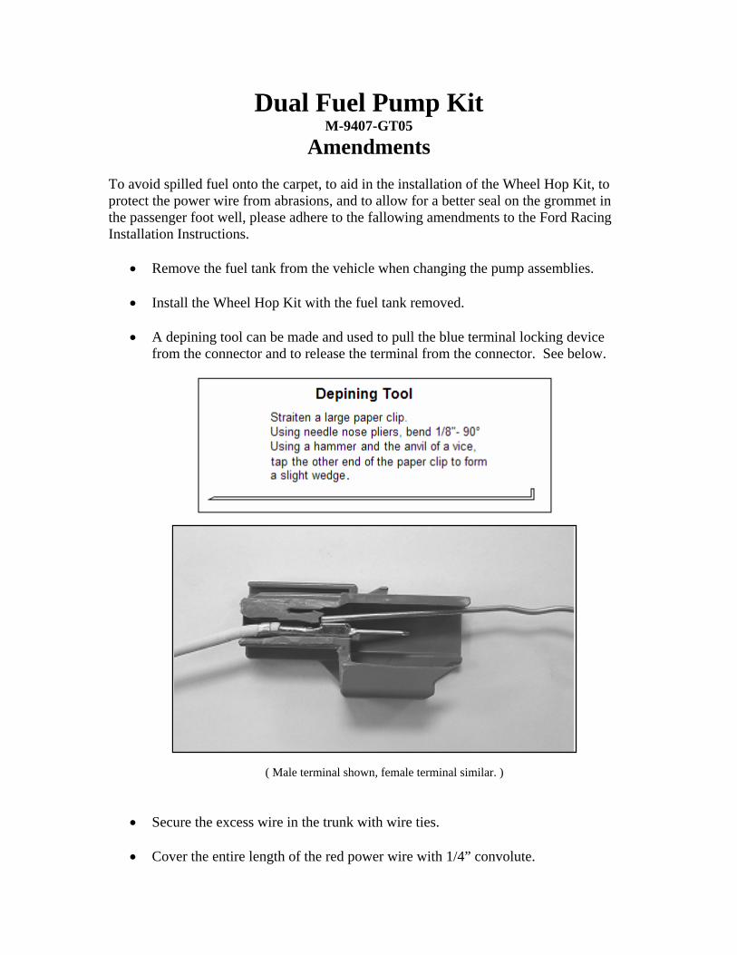
• A depining tool can be made and used to pull the blue terminal locking device from the connector and to release the terminal from the connector. See below.
( Male terminal shown, female terminal similar. )
• Secure the excess wire in the trunk with wire ties.
• Cover the entire length of the red power wire with 1/4” convolute.

• Cut the fuse holder from the red wire. Cut the end off of the wire nipple and pass the red wire and convolute through the opening. Wrap with tape as shown to seal the grommet.
• At the fuse box, cut the excess red wire for best fit and reattach the fuse holder to the red wire using the same technique used on the engine harness for the TPS and ACT wiring. Cover the wire with 1/4” convolute as shown.
• Secure the overlay harness to the vehicle main harness with wire ties placed every 10” to 12” and in the right front wheel well, every 6”.