installation instructions important: please read all
TRANSCRIPT
Walkerflex®
Modular Wiring System I N S T A L L A T I O N I N S T R U C T I O N SInstallation Instruction No.: 1 006 507 R6 – Updated August 2011
Wiremold electrical systems conform to and should be properlygrounded in compliance with requirements of the current NationalElectrical Code or codes administered by local authorities.
All electrical products may present a possible shock or fire hazard if improperly installed or used. Wiremold electrical productsmay bear the mark as UL Listed and/or Classified and should be installed in conformance with current local and/or theNational Electrical Code.
IMPORTANT: Please read all instructionsbefore beginning.
Products Covered: FCA, NWC, NCS, NCW, NCBS, NPA, NDU, RECDU, CAP3456, CAP810, LDU, LWC, LPA, LCBS,LCW, WWC, WCS, WCW, WPA, WCBS, WDU
NOTE: Label on product indicates which products are suitable for use in air handling spaces in accordance with Sec. 300-22(C) of the National Electric Code.
1. Each Walkerflex® component contains a unique connectorkey and color indicating rating, conductor location andorientation. Only like color keys can be mated. See KeyConfiguration and Color Chart for available options.
2. Each Walkerflex® key is comprised of one or moreconfigurations that determine the number of line and neutral conductors. Only identical configurations can be mated. See Key Configuration and Color Chart foravailable options.
3. Disconnect power from source prior to wiring any Walkerflex®
component into building’s electrical power system.4. Installer to determine maximum cable length based on wire
gauge and circuit load.5. Installer to ensure adequate overload protection based on
system key, rating and circuit load.
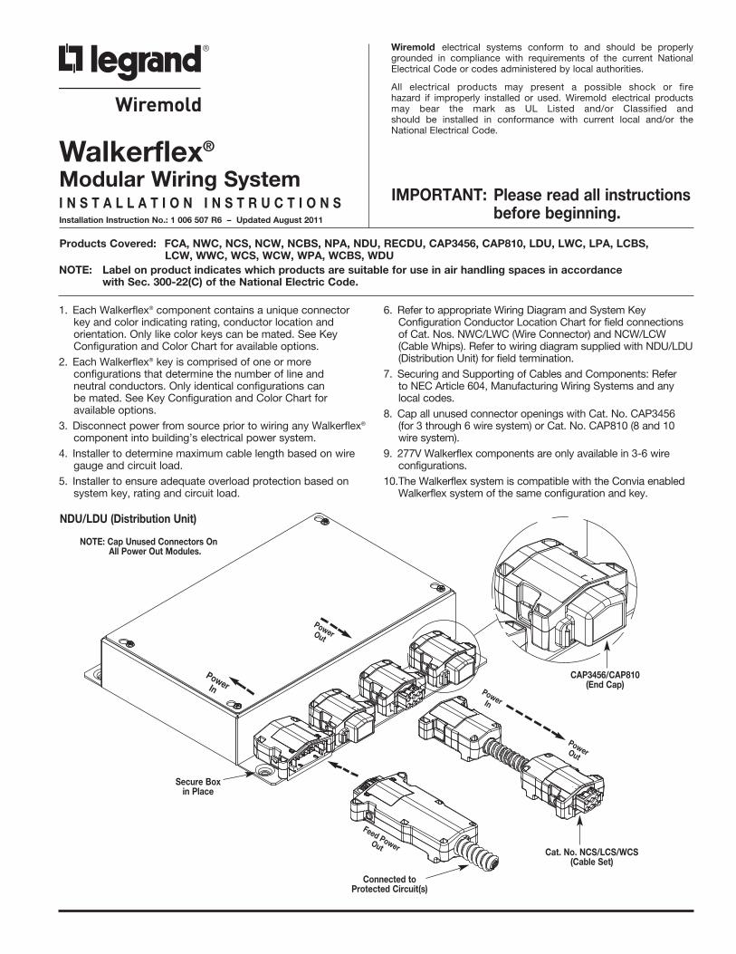
6. Refer to appropriate Wiring Diagram and System KeyConfiguration Conductor Location Chart for field connectionsof Cat. Nos. NWC/LWC (Wire Connector) and NCW/LCW(Cable Whips). Refer to wiring diagram supplied with NDU/LDU(Distribution Unit) for field termination.
7. Securing and Supporting of Cables and Components: Refer to NEC Article 604, Manufacturing Wiring Systems and anylocal codes.
8. Cap all unused connector openings with Cat. No. CAP3456 (for 3 through 6 wire system) or Cat. No. CAP810 (8 and 10wire system).
9. 277V Walkerflex components are only available in 3-6 wireconfigurations.
10.The Walkerflex system is compatible with the Convia enabledWalkerflex system of the same configuration and key.
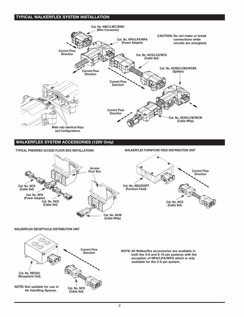
Cat. No. NCS/LCS/WCS(Cable Set)
CAP3456/CAP810(End Cap)
PowerOut
PowerIn
PowerOut
Connected toProtected Circuit(s)
Secure Boxin Place
NOTE: Cap Unused Connectors OnAll Power Out Modules.
NDU/LDU (Distribution Unit)
PowerIn
Feed PowerOut
2
Access Floor Box
TYPICAL PREWIRED ACCESS FLOOR BOX INSTALLATIONS
Cat. No. NCS(Cable Set)
Cat. No. NCS(Cable Set)
Cat. No. NCW(Cable Whip)
Cat. No. NPA(Power Adapter)
WALKERFLEX SYSTEM ACCESSORIES (120V Only)
TYPICAL WALKERFLEX SYSTEM INSTALLATION
WALKERFLEX FURNITURE FEED DISTRIBUTION UNIT
Cat. No. NDUXXXFF(Furniture Feed)
Cat. No. NCS(Cable Set)
Current FlowDirection
WALKERFLEX RECEPTACLE DISTRIBUTION UNIT
Cat. No. RECDU(Receptacle Unit)
Cat. No. NCS(Cable Set)
Current FlowDirection
Mate only identical Keysand Configurations.
Cat. No. NCS/LCS/WCS(Cable Set)
Current FlowDirection
Current FlowDirection
Cat. No. NCBS/LCBS/WCBS(Splitter)
Cat. No. NCW/LCW/WCW(Cable Whip)
Cat. No. NPA/LPA/WPA(Power Adapter)
Cat. No. NWC/LWC/WWC(Wire Connector)
Current FlowDirection
Current FlowDirection
CAUTION: Do not make or breakconnections whilecircuits are energized.
NOTE: All Walkerflex accessories are available inboth the 3-6 and 8-10 pin systems with theexception of NPA/LPA/WPA which is onlyavailable for the 3-6 pin system.
NOTE: Not suitable for use inAir Handling Spaces.
3
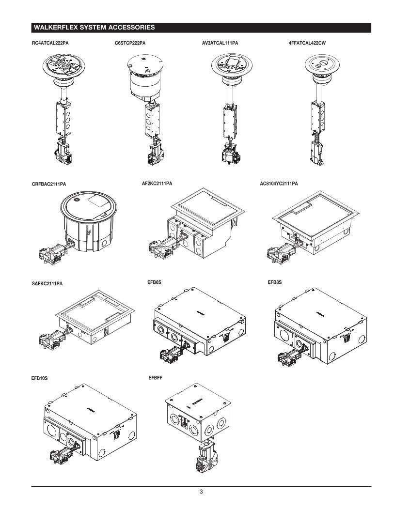
WALKERFLEX SYSTEM ACCESSORIES
RC4ATCAL222PA C6STCP222PA AV3ATCAL111PA 4FFATCAL422CW
CRFBAC2111PA AF2KC2111PA AC8104YC2111PA
SAFKC2111PA EFB6S EFB8S
EFB10S EFBFF
4
120V 20A SYSTEM FOR 1, 2, 3 OR 4 LINE CONDUCTORSCONNECTED TO A GROUNDED THREE-PHASE WYE
120V 20A SYSTEM FOR 1 OR 2 LINE CONDUCTORSCONNECTED TO A DUAL NEUTRAL GROUNDED THREE-PHASE WYE AND ISOLATED GROUND
120V 20A SYSTEM FOR 1 OR 2 LINE CONDUCTORSCONNECTED TO A DUAL NEUTRAL GROUNDED THREE-PHASE WYE
120V 20A SYSTEM FOR 1 OR 2 LINE CONDUCTORSCONNECTED TO A GROUNDED THREE-PHASE WYE AND ISOLATED GROUND
WALKERFLEX SYSTEM WIRING DIAGRAMS
277V 20A SYSTEM FOR 1, 2, OR 3 LINE CONDUCTORSCONNECTED TO A GROUNDED THREE-PHASE WYE
277V 20A SYSTEM FOR 1 OR 2 LINE CONDUCTORSCONNECTED TO A DUAL NEUTRAL GROUNDED THREE-PHASE WYE AND ISOLATED GROUND
L1 Black
277V 20A SYSTEM FOR 1 OR 2 LINE CONDUCTORSCONNECTED TO A DUAL NEUTRAL GROUNDED THREE-PHASE WYE
277V 20A SYSTEM FOR 1 OR 2 LINE CONDUCTORSCONNECTED TO A GROUNDED THREE-PHASE WYE AND ISOLATED GROUND
5
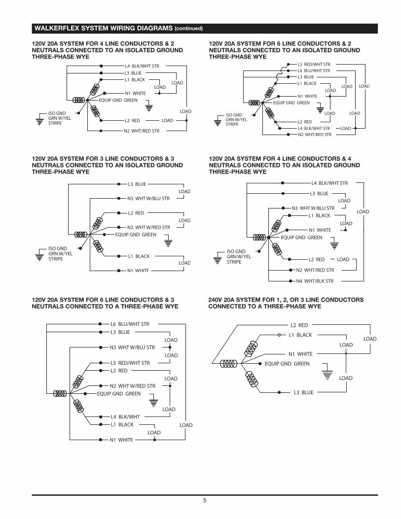
WALKERFLEX SYSTEM WIRING DIAGRAMS (continued)
120V 20A SYSTEM FOR 4 LINE CONDUCTORS & 2NEUTRALS CONNECTED TO AN ISOLATED GROUNDTHREE-PHASE WYE
120V 20A SYSTEM FOR 6 LINE CONDUCTORS & 2NEUTRALS CONNECTED TO AN ISOLATED GROUND THREE-PHASE WYE
120V 20A SYSTEM FOR 3 LINE CONDUCTORS & 3NEUTRALS CONNECTED TO AN ISOLATED GROUNDTHREE-PHASE WYE
120V 20A SYSTEM FOR 4 LINE CONDUCTORS & 4NEUTRALS CONNECTED TO AN ISOLATED GROUND THREE-PHASE WYE
120V 20A SYSTEM FOR 6 LINE CONDUCTORS & 3NEUTRALS CONNECTED TO A THREE-PHASE WYE
240V 20A SYSTEM FOR 1, 2, OR 3 LINE CONDUCTORSCONNECTED TO A THREE-PHASE WYE
6
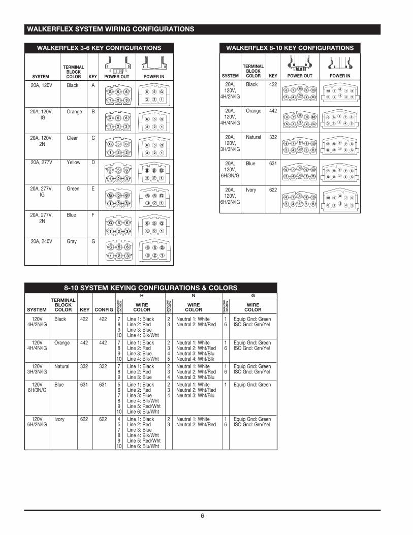
TERMINALBLOCK
SYSTEM COLOR KEY POWER OUT POWER IN
20A, Black 422120V,
4H/2N/IG
20A, Orange 442120V,
4H/4N/IG
20A, Natural 332120V,
3H/3N/IG
20A, Blue 631120V,
6H/3N/G
20A, Ivory 622120V,
6H/2N/IG
6 7 8
5 4 3
9 10
2 G
678
543
910
2G
6 78
5 4 3
9 10
2 G
678
543
910
2G
6 78
5 4 3
9 10
2 G
678
543
910
2G
6 78
5 4 3
9 10
2 G
678
543
910
2G
6 7 8
5 4 3
9 10
2 G
678
543
910
2G
WALKERFLEX 8-10 KEY CONFIGURATIONS
TERMINALBLOCK
SYSTEM COLOR KEY POWER OUT POWER IN
20A, 120V Black A
20A, 120V, Orange BIG
20A, 120V, Clear C2N
20A, 277V Yellow D
20A, 277V, Green EIG
20A, 277V, Blue F2N
20A, 240V Gray G
G 5 6
1 2 3
G56
123
G 5 6
1 2 3
G56
123
G 5 6
1 2 3
G56
123
WALKERFLEX 3-6 KEY CONFIGURATIONS
WALKERFLEX SYSTEM WIRING CONFIGURATIONS
H N GTERMINAL BLOCK WIRE WIRE WIRE
SYSTEM COLOR KEY CONFIG COLOR COLOR COLOR
120V Black 422 422 7 Line 1: Black 2 Neutral 1: White 1 Equip Gnd: Green4H/2N/IG 8 Line 2: Red 3 Neutral 2: Wht/Red 6 ISO Gnd: Grn/Yel
9 Line 3: Blue10 Line 4: Blk/Wht
120V Orange 442 442 7 Line 1: Black 2 Neutral 1: White 1 Equip Gnd: Green4H/4N/IG 8 Line 2: Red 3 Neutral 2: Wht/Red 6 ISO Gnd: Grn/Yel
9 Line 3: Blue 4 Neutral 3: Wht/Blu 10 Line 4: Blk/Wht 5 Neutral 4: Wht/Blk
120V Natural 332 332 7 Line 1: Black 2 Neutral 1: White 1 Equip Gnd: Green3H/3N/IG 8 Line 2: Red 3 Neutral 2: Wht/Red 6 ISO Gnd: Grn/Yel
9 Line 3: Blue 4 Neutral 3: Wht/Blu 120V Blue 631 631 5 Line 1: Black 2 Neutral 1: White 1 Equip Gnd: Green
6H/3N/G 6 Line 2: Red 3 Neutral 2: Wht/Red 7 Line 3: Blue 4 Neutral 3: Wht/Blu 8 Line 4: Blk/Wht 9 Line 5: Red/Wht 10 Line 6: Blu/Wht
120V Ivory 622 622 4 Line 1: Black 2 Neutral 1: White 1 Equip Gnd: Green6H/2N/IG 5 Line 2: Red 3 Neutral 2: Wht/Red 6 ISO Gnd: Grn/Yel
7 Line 3: Blue8 Line 4: Blk/Wht 9 Line 5: Red/Wht 10 Line 6: Blu/Wht
8-10 SYSTEM KEYING CONFIGURATIONS & COLORS
CONDUCTO
RLO
CAT
ION
CONDUCTO
RLO
CAT
ION
CONDUCTO
RLO
CAT
ION
7
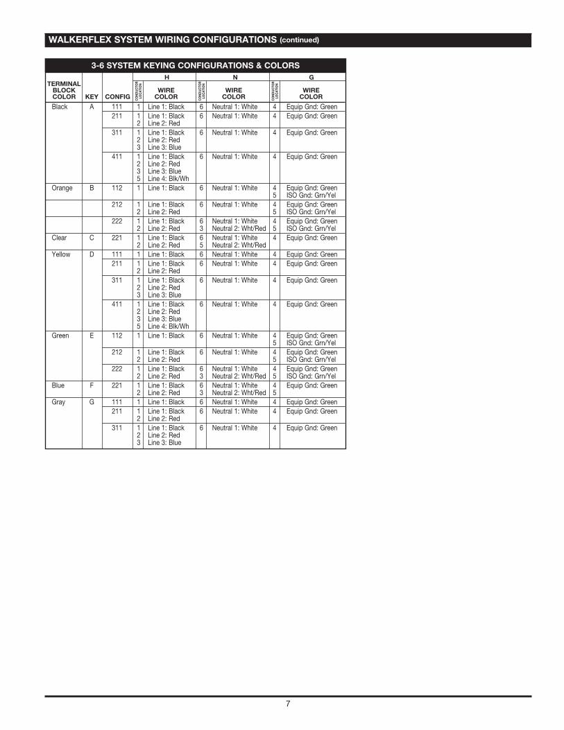
WALKERFLEX SYSTEM WIRING CONFIGURATIONS (continued)
CONDUCTO
RLO
CAT
ION
CONDUCTO
RLO
CAT
ION
CONDUCTO
RLO
CAT
ION
H N GTERMINAL BLOCK WIRE WIRE WIRECOLOR KEY CONFIG COLOR COLOR COLOR
Black A 111 1 Line 1: Black 6 Neutral 1: White 4 Equip Gnd: Green211 1 Line 1: Black 6 Neutral 1: White 4 Equip Gnd: Green
2 Line 2: Red311 1 Line 1: Black 6 Neutral 1: White 4 Equip Gnd: Green
2 Line 2: Red3 Line 3: Blue
411 1 Line 1: Black 6 Neutral 1: White 4 Equip Gnd: Green2 Line 2: Red3 Line 3: Blue5 Line 4: Blk/Wh
Orange B 112 1 Line 1: Black 6 Neutral 1: White 4 Equip Gnd: Green5 ISO Gnd: Grn/Yel
212 1 Line 1: Black 6 Neutral 1: White 4 Equip Gnd: Green2 Line 2: Red 5 ISO Gnd: Grn/Yel
222 1 Line 1: Black 6 Neutral 1: White 4 Equip Gnd: Green2 Line 2: Red 3 Neutral 2: Wht/Red 5 ISO Gnd: Grn/Yel
Clear C 221 1 Line 1: Black 6 Neutral 1: White 4 Equip Gnd: Green2 Line 2: Red 5 Neutral 2: Wht/Red
Yellow D 111 1 Line 1: Black 6 Neutral 1: White 4 Equip Gnd: Green211 1 Line 1: Black 6 Neutral 1: White 4 Equip Gnd: Green
2 Line 2: Red311 1 Line 1: Black 6 Neutral 1: White 4 Equip Gnd: Green
2 Line 2: Red3 Line 3: Blue
411 1 Line 1: Black 6 Neutral 1: White 4 Equip Gnd: Green2 Line 2: Red3 Line 3: Blue5 Line 4: Blk/Wh
Green E 112 1 Line 1: Black 6 Neutral 1: White 4 Equip Gnd: Green5 ISO Gnd: Grn/Yel
212 1 Line 1: Black 6 Neutral 1: White 4 Equip Gnd: Green2 Line 2: Red 5 ISO Gnd: Grn/Yel
222 1 Line 1: Black 6 Neutral 1: White 4 Equip Gnd: Green2 Line 2: Red 3 Neutral 2: Wht/Red 5 ISO Gnd: Grn/Yel
Blue F 221 1 Line 1: Black 6 Neutral 1: White 4 Equip Gnd: Green2 Line 2: Red 3 Neutral 2: Wht/Red 5
Gray G 111 1 Line 1: Black 6 Neutral 1: White 4 Equip Gnd: Green211 1 Line 1: Black 6 Neutral 1: White 4 Equip Gnd: Green
2 Line 2: Red311 1 Line 1: Black 6 Neutral 1: White 4 Equip Gnd: Green
2 Line 2: Red3 Line 3: Blue
3-6 SYSTEM KEYING CONFIGURATIONS & COLORS
WIREMOLDU.S. and International: 60 Woodlawn Street • West Hartford, CT 061101-800-621-0049 • FAX 860-232-2062 • Outside U.S.: 860-233-6251 Canada:570 Applewood Crescent • Vaughan, Ontario L4K 4B41-800-723-5175 • FAX 905-738-9721
1 006 507 R6 0811© Copyright 2011 Legrand All Rights Reserved
N O T E S