installation instructions round post adaptor...
TRANSCRIPT

• For gate gaps of 1” to 2” [1½” (38mm) is ideal] • For use on Magna-Latch® Top Pull and Vertical Pull models only.
For gates leading to swimming pools or spas, most Safety Codes specify the following minimum height requirements above the finished ground/fixing surface: 1) Latch release knob ‘F’ at minimum 54”-59” (1370-1500mm); 2) Fence height of between 4’ & 6’ (1220 & 1830mm). Always confirm these requirements with the appropriate authorities in your area and install this latch in accordance with your local fence/barrier Codes. Also, pool gates must open outward, away from the pool, so this latch must be fitted to the outside of a pool gate. Tools: Pencil, power drill, 5⁄32” (4mm) & 3⁄16” (5mm) drill-bits, measuring tape, Phillips No.2 driver bit & hand-held screwdriver, 5⁄16” (8mm) open-ended wrench, hacksaw, and metal file. Note: Use highest clutch setting on power drill for pre-drilling and starting screws. Use lower clutch setting to finish securing screws.ADAPTORS: Fence Post: Mounting Brackets A & B will fit onto 23⁄8” (60mm) diameter. Adaptors included for 17⁄8”-2” (48-51mm) and 27⁄8” (73mm) diameters. Gate Frame: Mounting bracket G is for 15⁄8” (41mm) diameter. Adaptors are included for 13⁄8” (35mm) diameter. NOTE: When using Adaptors on the Fence Post, be sure to insert the Dress Lugs for added strength before inserting screws into the Mounting Brackets.INSTALLATION INSTRUCTIONS1. Determine the location of Mounting Bracket ‘A’ on the Fence Post by measuring up from finished ground to the center of Bracket A (see dotted line). For 54” (1370mm) knob height, measure up 363⁄8” (925mm); for 59” (1500mm) knob height, measure up 413⁄8” (1050mm). Place Mounting Bracket ‘A’ on the post and be sure the face is in 180˚ align-ment with the fence line (Figure J). Mark the two side-fixing holes using the pencil. Pre-drill using 5⁄32” (4mm) drill bit. Insert two 1” (25mm) screws to fix Bracket ‘A’ to the post. Now pre-drill the two holes on the face of Bracket ‘A’ and insert two more screws.2. Install Mounting Bracket ‘B’ to the Fence Post: Be sure the face is in 180˚ alignment with the line of the fence (see J), and with the face of Bracket ‘A’. Top Pull: Measure up from the center of Bracket ‘A’ 133⁄8” (340mm). NOTE: For 48” (1200mm) high gates/fences without an extra-high post, this measurement should be 5” (125mm) for 54” (1370mm) Lift Knob height, and 10” (250mm) for 59” (1500mm) knob height. Vertical Pull: Measure up 3 5⁄8” (92mm) from Bracket ‘A’ . Mark the side-fixing hole using the pencil and pre-drill using the 5⁄32” (4mm) drill-bit. Insert one of the 1” (25mm) screws. Now do the same to the remaining fixing hole on the face of Bracket ‘B’.3. Take the main LATCH BODY ‘C’ and slide it down onto the Mounting Bracket ‘B’, ensuring the rear track of the latch slides over brackets ‘B’, then ‘A’.Slide the Latch Body down until the bottom of the latch aligns neatly with the lower end of Bracket ‘A’. Make sure the Lift Knob meets the desired height. Take the single 3⁄8” (10mm) countersunk Set Screw ‘H’ and secure the Latch Body to Bracket ‘A’. DO NOT use power drill – use hand-held screwdriver to fix Set Screw ‘H’ to Bracket ‘A’. DO NOT over tighten.4. Assembling STRIKER BODY ‘D’: Separate the square Mounting Bracket from Striker Body ‘D’. Turn the adjustment screw by using the hand-held screwdriver until the two parts separate. NEVER use a power drill as this may strip the adjustment screw. Replace with the round Mounting Bracket ‘G’. 5. Locate the Striker Body assembly onto the Gate Frame. Allow the Striker Body to engage the latch. Position the Striker Body to obtain a 1⁄8” (3mm) gap between the lower part of the latch and the top of the Striker Body (Figure E). Mark the Gate Frame drawing a line across the top and side of the Mounting Bracket so you can realign it later. Lift release knob ‘F’ and remove the Striker body. With the gate open, reposition the Mounting Bracket onto the gate using the two pencil lines. Mark the two holes on the face of the Mounting Bracket with the pencil. You may need to adjust the Striker Body to expose the two holes on the face. Pre-drill using the 3⁄16” (5mm) drill bit. Drill both holes through the other side of the Gate Frame. Be sure to drill the two holes straight on the diameter and not at an angle. Insert the two 3½” (90mm) bolts through the mounting bracket to the other side of the gate. Insert washers and thread nuts onto the bolts. Hand-tighten the nuts using the 5⁄16” (8mm) wrench. DO NOT over tighten the nuts. Cut off any excess bolt with the hacksaw. File smooth using the metal file.6. Mark the two holes on the side of Mounting Bracket ‘G’ and pre-drill using the 5⁄32” (4mm) drill bit. Insert the remaining two 1” screws. 7. Use the screwdriver to adjust the Striker Body to align with the Latch Body, as shown in Figure ‘E’. Open and close the gate to check that the latch operates correctly. Adjust as necessary at any time after installation to ensure safe opera-tion of the latch. NOTE: Future vertical adjustment of the latch can be achieved by removing the Set Screw ‘H’, sliding the Latch Body up or down the post to obtain correct operational alignment, then inserting the screw into the appropriate hole.Swimming pool fences, gates and latches can not substitute for adult supervision. If using this latch on a swimming pool gate, consult all appropriate local authori-ties for safety requirements, especially relating to gate gaps and climbing point. The latch will operate properly only if installed and maintained in accordance with these instructions.MAINTENANCE: REMOVE KEY FROM LOCK AFTER USE. Do not lubricate the latch with petroleum-based lubricants at any time; use only powdered graphite. Ensure all screws or bolts are tightened firmly and that the release knob [F] and latching bolt are kept free of sand, ice and other debris which could impair latch performance. Grind or remove any protruding fasteners after installation.
•Instru-MLTP 17/5 /07
INSTALLATION INSTRUCTIONS ROUND POST ADAPTOR KIT
®
MAGNETIC POOL GATE LATCH
®
MAGNETIC SAFETY GATE LATCH
MLSP2RPA000PA
AUSTRALIA: 6, 4-6 Aquatic Dr, Frenchs Forest NSW 2086USA: 7731 Woodwind Drive, Huntington Beach, CA 92647
www.ddtechglobal.com
WARRANTY & LIMITATION OF LIABILITY: D&D Technologiesʼ (“D&D”) products are warranted to be free of defects in materials and workmanship to the original purchaser for as long as he/she owns the product. If a structural defect appears, the original purchaser may return the item, freight prepaid, together with proof of purchase to D&D or its approved international agents. D&D or its agent will, at their discretion, repair or replace the defective item or part without charge to the purchaser. THIS WARRANTY SHALL NOT APPLY WHEN the product has been tampered with, when repairs or attempted repairs have been made by unauthorized persons, where the item has been subjected to misuse, abuse, accident or damage in transit, or where the installer has not followed the instructions set out during installation, operations, or maintenance requirements. IN NO EVENT SHALL THE COMPANY BE LIABLE FOR ANY INCIDENTAL OR CONSEQUENTIAL DAMAGES. No warranty is given other than that set out above. No other express or implied warranties (including statutory warranties) apply, other than warranties which may not be legally excluded.
LATCH BODY
STRIKER BODY
MOUNTING BRACKET
F
HA
B C
D
G
DRESSLUGS
DRESSLUGS
ADAPTORS
ADAPTORS
Align face of Mounting Brackets at 180˚
to fence lineM
OUNT
ING
BRAC
KETS
J
E
LIFT KNOB
FENC
E PO
ST
GATE
FRA
ME
MANTENIMIENTO: RETIRAR LA LLAVE DEL CERROJO DESPUÉS DE USAR. No lubricar el cerrojo con lubricantes a base de petróleo en ningún momento; usar únicamente grafito en polvo. Asegúrese de que todos los tornillos y pernos se encuentren firmemente ajustados y que el picaporte de soltar [F] y el perno del sujetador no tengan arena, hielo ni otros escombros que podrían impedir el funcionamiento del cerrojo. Lime o retire cualquier sujetador que sobresalga después de la instalación.
•Instru-MLTP SPAIN/USA 22/5/07
INSTRUCCIONES PARA LA INSTALACIÓN JUEGO DE ADAPTADOR PARA EL POSTE REDONDO
®
MAGNETIC POOL GATE LATCH
®
MAGNETIC SAFETY GATE LATCH
MLSP2RPA000PAAUSTRALIA: U6, 4-6 Aquatic Dr, Frenchs Forest NSW 2086USA: 7731 Woodwind Drive, Huntington Beach, CA 92647
www.ddtechglobal.com
GARANTÍA Y LIMITACIÓN DE LA RESPONSABILIDAD: Los productos de D&D Technologies (D&D) llevan una garantía al comprador original, de que están libres de defectos de materiales y mano de obra, mientras el producto pertenezca a dicha persona. Si aparece un defecto estructural, el comprador original podrá devolver el artículo, previo pago de flete, junto con evidencia de compra, a D&D o sus agentes internacionales aprobados. D&D o su agente, a su discreción, repararán o reemplazarán el artículo defectuoso o parte defectuosa en forma gratuita. ESTA GARANTÍA NO TENDRÁ APLICABILIDAD CUANDO se haya modificado el producto, cuando personas no autorizadas lo hayan reparado o intentado repararlo, cuando el artículo haya sido objeto de uso incorrecto, abuso, o haya sufrido accidentes o daños en tránsito, o cuando la persona que lo haya instalado no haya seguido, durante la instalación o funcionamiento, las instrucciones o los Requisitos de Mantenimiento que se establecen. EN NINGÚN CASO LA EMPRESA SE HARÁ RESPONSABLE DE DAÑOS INCIDENTALES O EMERGENTES. No se otorga otra garantía que la que se establece más arriba. No se aplica ninguna otra garantía, expresa o implícita (incluidas las garantías estatutarias), a menos que sean garantías que no puedan excluirse por ley.
CAjA DEL CERROjO
CAjA DE LA CERRADURA
hEMBRA
SOPORTE PARA MONTAjE
F
hA
B C
D
GADAPTADORES
Alinear la cara de los sujetadores para montaje a 180 grados de la línea de la cerca
SOPO
RTES
PARA
MO
NTAj
E
j
E
PICAPORTE DE LEvANTE
ADAPTADORES
SALIENTES DE RECUBRIMIENTO
SALIENTES DE RECUBRIMIENTO
POST
E DE L
A CE
RCA
MAR
CO D
E LA
PUER
TA
ESPACIO DE 1⁄8” (3mm)
Para
un pi
caport
e de 5
4” m
edir h
acia
arriba
36 3 ⁄8”
(925
mm).
Para
un pi
caport
e de 5
9”, m
edir
hacia
arrib
a 41 3 ⁄8”
(105
0mm)
.
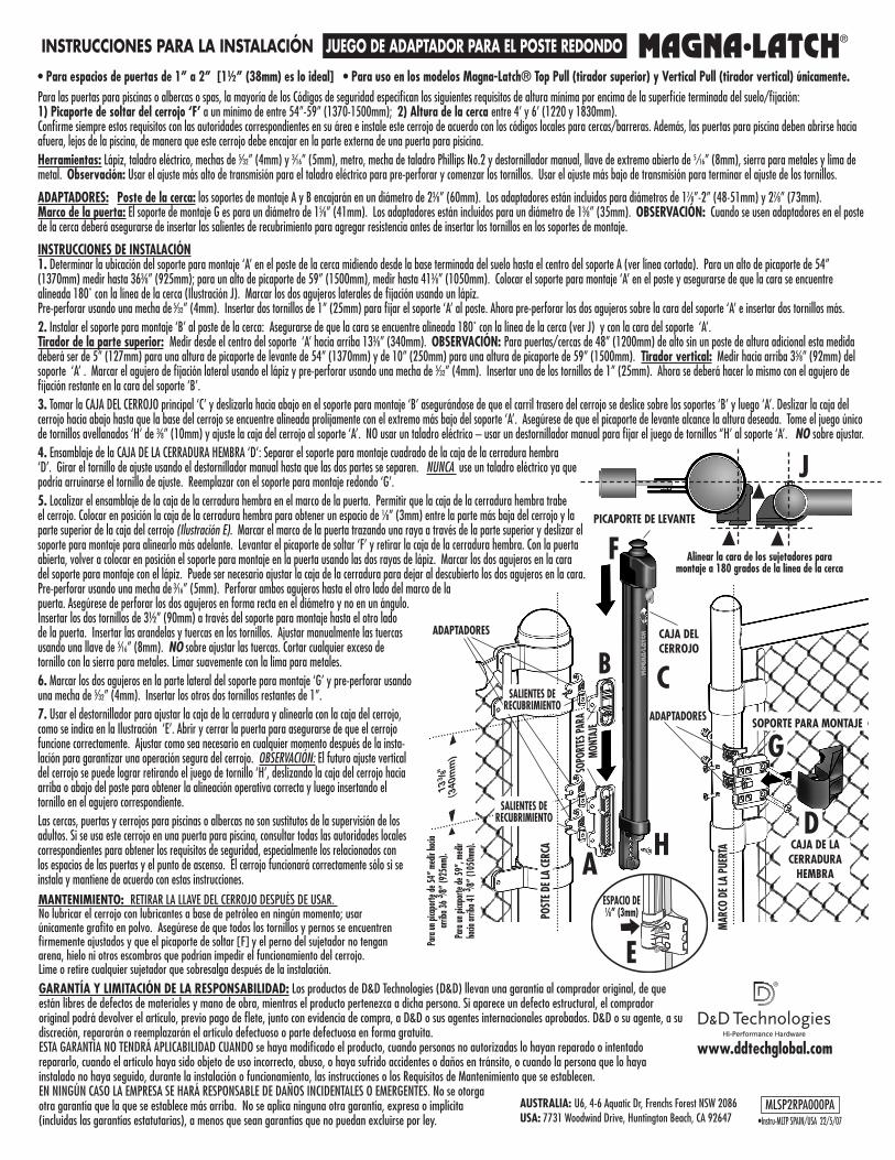
• Para espacios de puertas de 1” a 2” [1½” (38mm) es lo ideal] • Para uso en los modelos Magna-Latch® Top Pull (tirador superior) y vertical Pull (tirador vertical) únicamente.Para las puertas para piscinas o albercas o spas, la mayoría de los Códigos de seguridad especifican los siguientes requisitos de altura mínima por encima de la superficie terminada del suelo/fijación: 1) Picaporte de soltar del cerrojo ‘F’ a un mínimo de entre 54”-59” (1370-1500mm); 2) Altura de la cerca entre 4’ y 6’ (1220 y 1830mm). Confirme siempre estos requisitos con las autoridades correspondientes en su área e instale este cerrojo de acuerdo con los códigos locales para cercas/barreras. Además, las puertas para piscina deben abrirse hacia afuera, lejos de la piscina, de manera que este cerrojo debe encajar en la parte externa de una puerta para pisicina. herramientas: Lápiz, taladro eléctrico, mechas de 5⁄32” (4mm) y 3⁄16” (5mm), metro, mecha de taladro Phillips No.2 y destornillador manual, llave de extremo abierto de 5 ⁄16” (8mm), sierra para metales y lima de metal. Observación: Usar el ajuste más alto de transmisión para el taladro eléctrico para pre-perforar y comenzar los tornillos. Usar el ajuste más bajo de transmisión para terminar el ajuste de los tornillos.
ADAPTADORES: Poste de la cerca: los soportes de montaje A y B encajarán en un diámetro de 23⁄8” (60mm). Los adaptadores están incluidos para diámetros de 17⁄8”-2” (48-51mm) y 27⁄8” (73mm). Marco de la puerta: El soporte de montaje G es para un diámetro de 15⁄8” (41mm). Los adaptadores están incluidos para un diámetro de 13⁄8” (35mm). OBSERvACIÓN: Cuando se usen adaptadores en el poste de la cerca deberá asegurarse de insertar las salientes de recubrimiento para agregar resistencia antes de insertar los tornillos en los soportes de montaje.
INSTRUCCIONES DE INSTALACIÓN1. Determinar la ubicación del soporte para montaje ‘A’ en el poste de la cerca midiendo desde la base terminada del suelo hasta el centro del soporte A (ver línea cortada). Para un alto de picaporte de 54” (1370mm) medir hasta 363⁄8” (925mm); para un alto de picaporte de 59” (1500mm), medir hasta 413⁄8” (1050mm). Colocar el soporte para montaje ‘A’ en el poste y asegurarse de que la cara se encuentre alineada 180˚ con la línea de la cerca (Ilustración J). Marcar los dos agujeros laterales de fijación usando un lápiz. Pre-perforar usando una mecha de 5⁄32” (4mm). Insertar dos tornillos de 1” (25mm) para fijar el soporte ‘A’ al poste. Ahora pre-perforar los dos agujeros sobre la cara del soporte ‘A’ e insertar dos tornillos más.2. Instalar el soporte para montaje ‘B’ al poste de la cerca: Asegurarse de que la cara se encuentre alineada 180˚ con la línea de la cerca (ver J) y con la cara del soporte ‘A’. Tirador de la parte superior: Medir desde el centro del soporte ‘A’ hacia arriba 133⁄8” (340mm). OBSERvACIÓN: Para puertas/cercas de 48” (1200mm) de alto sin un poste de altura adicional esta medida deberá ser de 5” (127mm) para una altura de picaporte de levante de 54” (1370mm) y de 10” (250mm) para una altura de picaporte de 59” (1500mm). Tirador vertical: Medir hacia arriba 35⁄8” (92mm) del soporte ‘A’ . Marcar el agujero de fijación lateral usando el lápiz y pre-perforar usando una mecha de 5⁄32” (4mm). Insertar uno de los tornillos de 1” (25mm). Ahora se deberá hacer lo mismo con el agujero de fijación restante en la cara del soporte ‘B’.3. Tomar la CAJA DEL CERROJO principal ‘C’ y deslizarla hacia abajo en el soporte para montaje ‘B’ asegurándose de que el carril trasero del cerrojo se deslice sobre los soportes ‘B’ y luego ‘A’. Deslizar la caja del cerrojo hacia abajo hasta que la base del cerrojo se encuentre alineada prolijamente con el extremo más bajo del soporte ‘A’. Asegúrese de que el picaporte de levante alcance la altura deseada. Tome el juego único de tornillos avellanados ‘H’ de 3⁄8” (10mm) y ajuste la caja del cerrojo al soporte ‘A’. NO usar un taladro eléctrico – usar un destornillador manual para fijar el juego de tornillos “H’ al soporte ‘A’. NO sobre ajustar.4. Ensamblaje de la CAJA DE LA CERRADURA HEMBRA ‘D’: Separar el soporte para montaje cuadrado de la caja de la cerradura hembra ‘D’. Girar el tornillo de ajuste usando el destornillador manual hasta que las dos partes se separen. NUNCA use un taladro eléctrico ya que podría arruinarse el tornillo de ajuste. Reemplazar con el soporte para montaje redondo ‘G’. 5. Localizar el ensamblaje de la caja de la cerradura hembra en el marco de la puerta. Permitir que la caja de la cerradura hembra trabe el cerrojo. Colocar en posición la caja de la cerradura hembra para obtener un espacio de 1⁄8” (3mm) entre la parte más baja del cerrojo y la parte superior de la caja del cerrojo (Ilustración E). Marcar el marco de la puerta trazando una raya a través de la parte superior y deslizar el soporte para montaje para alinearlo más adelante. Levantar el picaporte de soltar ‘F’ y retirar la caja de la cerradura hembra. Con la puerta abierta, volver a colocar en posición el soporte para montaje en la puerta usando las dos rayas de lápiz. Marcar los dos agujeros en la cara del soporte para montaje con el lápiz. Puede ser necesario ajustar la caja de la cerradura para dejar al descubierto los dos agujeros en la cara. Pre-perforar usando una mecha de 3⁄16” (5mm). Perforar ambos agujeros hasta el otro lado del marco de la puerta. Asegúrese de perforar los dos agujeros en forma recta en el diámetro y no en un ángulo. Insertar los dos tornillos de 3½” (90mm) a través del soporte para montaje hasta el otro lado de la puerta. Insertar las arandelas y tuercas en los tornillos. Ajustar manualmente las tuercas usando una llave de 5⁄16” (8mm). NO sobre ajustar las tuercas. Cortar cualquier exceso de tornillo con la sierra para metales. Limar suavemente con la lima para metales. 6. Marcar los dos agujeros en la parte lateral del soporte para montaje ‘G’ y pre-perforar usando una mecha de 5⁄32” (4mm). Insertar los otros dos tornillos restantes de 1”. 7. Usar el destornillador para ajustar la caja de la cerradura y alinearla con la caja del cerrojo, como se indica en la Ilustración ‘E’. Abrir y cerrar la puerta para asegurarse de que el cerrojo funcione correctamente. Ajustar como sea necesario en cualquier momento después de la insta-lación para garantizar una operación segura del cerrojo. OBSERVACIÓN: El futuro ajuste vertical del cerrojo se puede lograr retirando el juego de tornillo ‘H’, deslizando la caja del cerrojo hacia arriba o abajo del poste para obtener la alineación operativa correcta y luego insertando el tornillo en el agujero correspondiente.Las cercas, puertas y cerrojos para piscinas o albercas no son sustitutos de la supervisión de los adultos. Si se usa este cerrojo en una puerta para piscina, consultar todas las autoridades locales correspondientes para obtener los requisitos de seguridad, especialmente los relacionados con los espacios de las puertas y el punto de ascenso. El cerrojo funcionará correctamente sólo si se instala y mantiene de acuerdo con estas instrucciones.