installation manual automatic faucet - …‘¢place the spout into the wash basin hole....
TRANSCRIPT
TM
TM
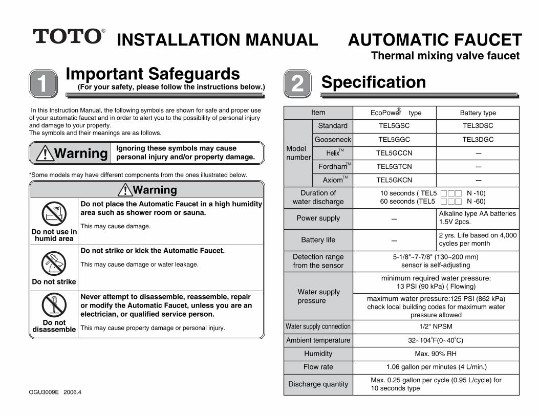
INSTALLATION MANUAL AUTOMATIC FAUCETThermal mixing valve faucet
Important Safeguards(For your safety, please follow the instructions below.)
In this Instruction Manual, the following symbols are shown for safe and proper useof your automatic faucet and in order to alert you to the possibility of personal injuryand damage to your property.The symbols and their meanings are as follows.
Warning Ignoring these symbols may causepersonal injury and/or property damage.
*Some models may have different components from the ones illustrated below.
Do not place the Automatic Faucet in a high humidityarea such as shower room or sauna. This may cause damage.
Do not use inhumid area
Warning
Do not strike or kick the Automatic Faucet.
This may cause damage or water leakage.
Never attempt to disassemble, reassemble, repairor modify the Automatic Faucet, unless you are anelectrician, or qualified service person.
This may cause property damage or personal injury.Do not
disassemble
Do not strike
Specification
OGU3009E 2006.4
EcoPower type Battery type
Modelnumber
Standard
Gooseneck
Power supply -
-
Alkaline type AA batteries1.5V 2pcs.
Battery life
Item
2 yrs. Life based on 4,000cycles per month
Detection rangefrom the sensor
5-1/8"~7-7/8" (130~200 mm)sensor is self-adjusting
Water supplypressure
minimum required water pressure:13 PSI (90 kPa) ( Flowing)
maximum water pressure:125 PSI (862 kPa)check local building codes for maximum water
pressure allowed
Water supply connection 1/2" NPSM
TEL5GSC TEL3DSC
TEL5GGC TEL3DGC
Helix TEL5GCCN -
Fordham TEL5GTCN -
Axiom TEL5GKCN -
Ambient temperature 32~104oF(0~40oC)
Humidity Max. 90% RH
Flow rate 1.06 gallon per minutes (4 L/min.)
Duration ofwater discharge
Discharge quantity Max. 0.25 gallon per cycle (0.95 L/cycle) for10 seconds type
10 seconds ( TEL5 N -10)60 seconds (TEL5 N -60)
TM

Before Installing
1. Check the pressure of cold and hot water supply
2. Check the temperature of hot-water supply
3. Piping
4. Others
Make sure the cold water supply pressure is higher or equal to the hot watersupply pressure.When the water supply pressure is higher than 125PSI (862kPa), be sure toreduce the pressure within a range of 20 to 80 PSI by using a pressurereducing valve available in the market.
Optimum working pressure range is from 7PSI to 125PSI (60kPa to 862kPa).Make sure the water pressure is within this range.
Never use steam as a hot-water supply.
Make sure the temperature range of hot-water supply is within 140 to185oF(60 to 85oC).This is not mandatory for the lower limit but is recommended.The Automatic Faucet does not discharge hot water exceeding 122oF(50oC).
Flush all water lines prior to installation.
Pay special attention so that the sensor surface is not �awed or scratched.
Prepare stop valve and �exible hose or copper tube.
Do not place other devices using inverter or infrared sensor near theAutomatic Faucet, this may cause malfunction.
There is no problem with the Automatic Faucet if the water remains inside.
Set-up DrawingSome models may have di�erent components as illustrated below.
Battery type
1"(25mm)
1"(25mm)
1-2/3"(42mm)3-3/4"
(95mm)
1-1/2"(38mm)
8"(203mm) 6"
(152mm)6-1/2"(165mm)
10-1/4"(260mm) 34"
(864mm)
17-1/8"(436mm)
16-7/8"(428mm)
HOT
COLD
F.L.
1"(25mm)
1"(25mm)
1-2/3"(42mm)3-3/4"
(95mm)
1-1/2"(38mm)
8"(203mm)
6"(152mm)
6-1/2"(165mm)
10-1/4"(260mm)
34"(864mm)
17-1/8"(436mm)
16-7/8"(428mm)HOT
COLD
F.L.
EcoPower type

H
C
H
C
Installation*Some models may have di�erent component as illustrated below. Optional Accessories (Not included)
Adjustable wrench, phillips and �at head screwdrivers
Battery typeEcoPower type
Control box Water inlet bracket Plate
4" Plate (TN71V100R) 8" Plate (71244T8CC)
Nut
Lockwasher
Washer
4" Plate
Packing
8" Plate
Baseplate
Packing
Washer
Wing nut
Tie bolt
Packing
O-ring
Installation manual Instruction
manual
Alkaline AABattery(×2)Battery case
Others
Screw(φ3 mm×10)
Allen wrenchSize:1/16"(2mm)
Battery type
*Spout , Flexible tube and Open-close tool are included.
Gooseneck Helix Fordham AxiomStandard
Spout Flexible tube
Open-close tool
Others
※Flexible tube is installed through spout connecting hose.
Required Tools
Water inlet bracket (×2)
Self tapping screw (×8)(φ4.5 mm×38)
EcoPower type
H
C
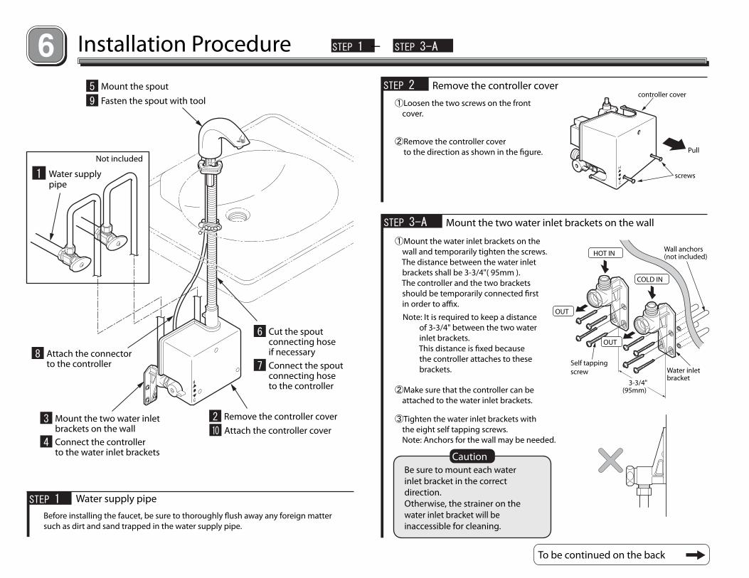
Installation Procedure STEP 1 - STEP 3-A
5 Mount the spout
9 Fasten the spout with tool
Not included
1 Water supplypipe
8 Attach the connectorto the controller
3 Mount the two water inletbrackets on the wall
4 Connect the controllerto the water inlet brackets
2 Remove the controller cover
10 Attach the controller cover
6 Cut the spoutconnecting hoseif necessary
7 Connect the spoutconnecting hoseto the controller
STEP 1 Water supply pipe
Before installing the faucet, be sure to thoroughly �ush away any foreign mattersuch as dirt and sand trapped in the water supply pipe.
STEP 2 Remove the controller cover
①Loosen the two screws on the front cover.
②Remove the controller cover to the direction as shown in the �gure.
controller cover
screws
Pull
STEP 3-A Mount the two water inlet brackets on the wall
①Mount the water inlet brackets on the wall and temporarily tighten the screws. The distance between the water inlet brackets shall be 3-3/4"( 95mm ). The controller and the two brackets should be temporarily connected �rst in order to a�x.
To be continued on the back
Be sure to mount each waterinlet bracket in the correctdirection. Otherwise, the strainer on thewater inlet bracket will beinaccessible for cleaning.
Caution
Wall anchors(not included)
Water inletbracket
Self tappingscrew
COLD IN
OUT
HOT IN
OUT
3-3/4"(95mm)
Note: It is required to keep a distance of 3-3/4" between the two water inlet brackets. This distance is �xed because the controller attaches to these brackets.
②Make sure that the controller can be attached to the water inlet brackets.
③Tighten the water inlet brackets with the eight self tapping screws. Note: Anchors for the wall may be needed.

STEP 3-B - STEP 6
STEP 3-B Mount the two water inlet brackets on the wall
Note: Remove all protective covers.
④Connect the hot/cold water supply lines to the water inlet brackets.
Flexible hose Copper tube
Note: Make sure hot goes on the left side.
Flexible hose
Copper tube
Nut
Nut
Packing
Friction ringCone washer
not included
not included
STEP 4 Connect the controller to the water inlet bracketsNote: Remove all protective covers.
After placing packing, attach thecontroller to the water inlet brackets, and then a�x them with the nuts asshown in the �gure.
※Packing is located on the water inlet bracket.
Packing
Water inlet bracket
Nut
Controller
STEP 5 Mount the spout
①Remove the �exible tube from the spout connecting hose.
②Mount the cover plate (optional).
③Place the spout into the wash basin hole.
④Hand-tighten the washer with the hexagonal nut.
Caution
Spout
Washer
Hexagonal nut
Wash basin
Cord
Spout connectinghose
Plate (optional)
STEP 6 Cut the spout connecting hose if necessary
①Cut the spout connecting hose to the appropriate length.
※If the spout connecting hose is too long, cut it to proper length. Do not cut the hose more than 4 inches. Be sure to cut the hose carefully with a cutter, so the surface is square.
②Insert the spout connecting hose into the �exible tube.
Clean the hoseend after cutting. Spout connecting
hose
Spout connectinghose
Flexible tube
Cutting length:4 inches or less
90゜
Pay special attention to avoidentangling the spout connectinghose and cord with each other.

+ +
STEP 7 Connect the spout connecting hose to the controller
①Insert the spout connecting hose into the controller.
②Tighten the cap nut by hand.
※Make sure the hose is securely connected, and is not kinked or bent.
STEP 7 - STEP 8-B
STEP 8-A Attach the connector to the controller
①Attach the back-up battery connector (white) to the controller.
②Allow the circuit board to stabilize for 2 minutes, then attach the sensor connector (green).
<For EcoPower type>
Flexible tube
Spout connectinghose
Cap nut
Controller
Sensor connector (green)
Back-up batteryconnector (white)
EcoPower type needs about twominutes for its controller to beready for operation after attachingthe back-up connector to thecontroller.
Caution
STEP 8-B Attach the connector to the controller
①Install the two batteries into the battery case exactly as shown in the �gure.
<For Battery type>
②Install the battery case into the controller.
③Attach the battery connector (white) to the controller.
④Attach the sensor connector (green) to the controller.
●Make sure there are no obstructions between the sensor and the basin. The controller starts setting right after the sensor connector is attached. (This sensor setting operation is completed in approx 20 seconds.)●Make sure that no electric cord comes in contact with the hot water supply pipe.
Caution
There is a risk of explosion ifthe battery is replaced by anincorrect type.Dispose of used batteryaccording to the instructions.
Caution
Sensor connector (green)
batteries
battery case
Battery connector (white)
battery case
controller

STEP 9 Fasten the spout
Be sure to mount the faucetbody with its spout tip directedtoward the basin center.
①A�x the spout by tightening the hexagonal nut.
Caution
STEP 9 - STEP 10
The light will only blink for 10 minutes. If all adjustment arenot made during this 10minutes, unplug sensorconnector for 10 seconds toreset the unit.
②Con�rm there are no obstructions within the detection range.
※If light continues to �ash, the spout direction will need to be readjusted for proper operation.
Caution
STEP 10 Attach the controller coverAfter checking the connectors aresecurely attached, cover the controller.
Spout position
On the right side
Drain
Drain
Spout
Basin center
At the centerSpout
Sensor Sensor light
Sensor connector (green)
Cover
Screw

Function Test
1. Checking after installation
After your Automatic Faucet is installed, check it according to the following procedures.
①Check for water leakage Open the stop valve and check for water leakage.②Operation <Check the sensor operation> ・When hands are placed under the faucet, water starts �owing. ・When hands are removed, water stops in one or two seconds. ・For safety and conservation reasons, after detecting objects continuously for about 10 seconds or 60 seconds, water automatically stops.
If the Automatic Faucet does not operate properly, contact TOTO or yourplumbing contractor.
3. Cleaning of the strainer
※Close stop valve by hand. Use the open-close tool to remove the strainer cover.
After installation, be sure to clean the strainerperiodically.When the strainer is clogged, the �ow rate willdecrease and the Automatic Faucet may notoperate properly.
2. Temperature adjustment
The water temperature has been factoryset to 100°F(38°C, Max:42°±3°C). Depending on the supply water pressureand other local conditions, the watertemperature may not be kept as speci�ed. In such a case, adjust the temperatureby turning the temperature control handle.Note : If water temperature goes opposite direction, make sure hot & cold connection is right side or not.
Temperature control handle Hot
Cold
Strainer
Strainer cover
Open-close tool
The �ow controller regulates �ow rate to 1.06gpm (4 L/min.), there is no need to adjust the�ow rate. Use the Automatic Faucet with the stop valvefully opened.However, if you need to regulate the �ow ratebecause the wash basin is small or that thewater supply pressure is too strong, adjust the�ow rate by turning the stop valve clockwise.
The EcoPower type must be used withthe stop valve fully opened.Insu�cient �ow rate may cause powershortage, resulting in consumption ofthe built-in back-up battery.
※If you need to regulate the �ow rate, make sure that the �ow rate is more than 0.8gpm ( 3L / min).※The water appears white with �ow rate of more than 0.8gpm(3L/min.).
4.Adjustment of �ow rate
Caution
Stop valve
Open
Close
The water appearswhite with �ow rateof more than0.8gpm(3L/min.).
regulation valvestop ring
power unit