installation manual flush mount - shingle, slate ,etc. · installation manual flush mount -...
TRANSCRIPT
INS
TALL
ATIO
N M
AN
UA
LS
©TRA Snow and Sun, Inc., 2012SE12091
Installation ManualFLUSH MOUNT - Shingle, Slate ,etc.
At TRA Snow and Sun we engineer and layout each project upon request free of charge. Just give us the project details and we will give you the rail spans, max loads on components, wind parameters, solar panel geometry, force per foot on rail and panels, a schematic of the module field, the wind speed, shipping weight, and project details.

INS
TALL
ATIO
N M
AN
UA
L
©TRA Snow and Sun, Inc., 2012SE12092
The L Base Roof Mounts can be used on the following roof types:
INSTALLING THE L BASE ROOF MOUNTSEach L Base must be attached using (2) Simpson Strong Drive SDS type screws and must be fastened directly into the roof framing below the roof decking (i.e. truss, purlin, beam, etc.) The use of the SDS screw allows installation without pre-drilling
• The first fastener is to be placed in the top (up-slope) slotted hole of the L Base. Do not tighten the screw completely as this will allow for vertical mount adjustment. Install all L Base Roof Mounts using this method.
• Once the mounts are fastened, they may be adjusted vertically to ensure proper alignment. The second fastener should then be placed in the non-slotted hole to secure the position of the L Base Roof Mount. Once the second fastener is in place, the first fastener may be tightened to fix the Roof Mount securely to the roof.
NOTE: It is important to align all Roof Mounts horizontally to prevent unnecessary tension on the mounting rails. Certain L Base Roof Mounts do not have slotted holes and cannot be adjusted vertically.
To obtain a warranted system TRA Snow and Sun must provide an engineered design. At the very minimum we strongly recommend these guidelines be followed:
Asphalt Shingles Slate/Simulated Slate Shakes/Simulated Shake Wood Shingle Metal Shingle
(without flashing)

INS
TALL
ATIO
N M
AN
UA
L
©TRA Snow and Sun, Inc., 2012SE12093
PREPARING TO MOUNT THE RAILS
If waterproofing the Roof Mount locations is required, the Standard Roof Mount Flashing may be used.
• Slide the tail of the flashing under the head lap of the roofing material directly above the installed Roof Mount and rotate the flashing down so that its final position is centered horizontally over the mount.
• Fasten/Adhere flashing in place following NRCA Standards or roofing material manufacturer specifications.
NOTE: The roofing material must lap over the Standard Roof Mount Flashing as shown.
FLASHING (optional)
! Flashing can be manufactured with a head lap length from 2″ to 12″ depending on the type of the roofing material.
INSTALLING THE RAILS• The Rails are to be attached to the L Base Roof Mount
using the vertical slotted hole and are to be parallel to the roof eave.
• Attach the Rails to the L Base Roof Mount using a Socket Head Cap Screw and Sliding Block. Install the screw through the L Base Roof Mount into the Rail and Sliding Block.
• Tighten the Socket Head Cap Screw until it tightly holds the rail. (15 PSF torque)
INS
TALL
ATIO
N M
AN
UA
L
©TRA Snow and Sun, Inc., 2012SE12094
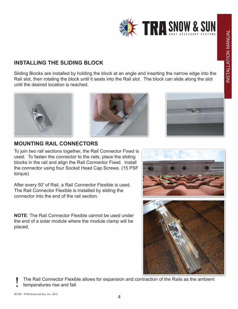
INSTALLING THE SLIDING BLOCK
Sliding Blocks are installed by holding the block at an angle and inserting the narrow edge into the Rail slot, then rotating the block until it seats into the Rail slot. The block can slide along the slot until the desired location is reached.
NOTE: The Rail Connector Flexible cannot be used under the end of a solar module where the module clamp will be placed.
! The Rail Connector Flexible allows for expansion and contraction of the Rails as the ambient temperatures rise and fall.
MOUNTING RAIL CONNECTORSTo join two rail sections together, the Rail Connector Fixed is used. To fasten the connector to the rails, place the sliding blocks in the rail and align the Rail Connector Fixed. Install the connector using four Socket Head Cap Screws. (15 PSF torque)
After every 50′ of Rail, a Rail Connector Flexible is used. The Rail Connector Flexible is installed by sliding the connector into the end of the rail section.

INS
TALL
ATIO
N M
AN
UA
L
©TRA Snow and Sun, Inc., 2012SE12095
INSTALLING THE CROSS BRACING SYSTEM
• The mounting layout for a single-layer or cross braced system can be determined from a roof configuration layout provided by TRA Snow and Sun. In the care of a cross-braced mounting systems, the mounting rails are installed using a Cross Connector, Sliding Block and a Socket Head Cap Screw.
• To mount the rails in a cross-braced patter, the Cross Connector is installed on the bottom Rail using a Socket Head Cap Screw fastened through the Cross Connector into the Sliding Block. The upper rail is installed perpendicular to the bottom rail by aligning the Cross Connector with of sliding block channel of the upper Rail and attaching the rail with a Socket Head Cap Screw.
• Tighten all connections securely so there will be no movement of the Rails. (15 PSF torque)
INS
TALL
ATIO
N M
AN
UA
L
©TRA Snow and Sun, Inc., 2012SE12096
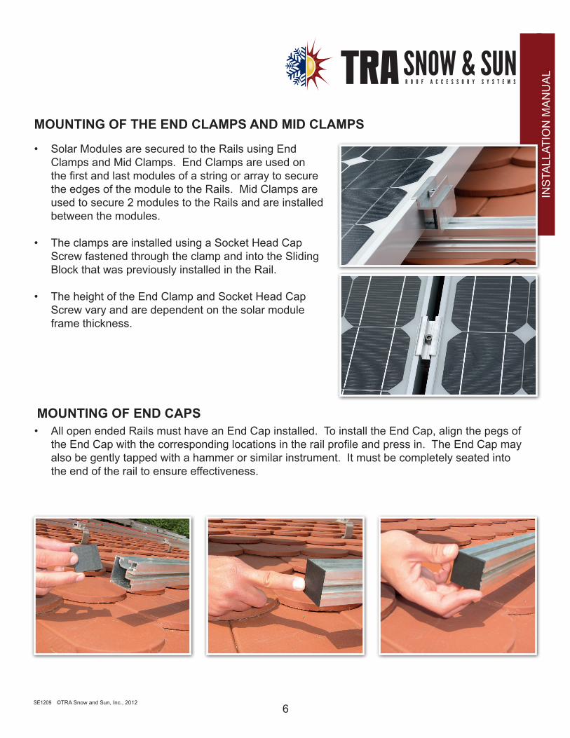
• All open ended Rails must have an End Cap installed. To install the End Cap, align the pegs of the End Cap with the corresponding locations in the rail profile and press in. The End Cap may also be gently tapped with a hammer or similar instrument. It must be completely seated into the end of the rail to ensure effectiveness.
MOUNTING OF THE END CLAMPS AND MID CLAMPS
• Solar Modules are secured to the Rails using End Clamps and Mid Clamps. End Clamps are used on the first and last modules of a string or array to secure the edges of the module to the Rails. Mid Clamps are used to secure 2 modules to the Rails and are installed between the modules.
• The clamps are installed using a Socket Head Cap Screw fastened through the clamp and into the Sliding Block that was previously installed in the Rail.
• The height of the End Clamp and Socket Head Cap Screw vary and are dependent on the solar module frame thickness.
MOUNTING OF END CAPS