mounting on the ceiling using flush mount (face down)
TRANSCRIPT
2014/02/14
Mounting on the Ceiling
Using Flush Mount
(Face Down)
Installation Guide
www.acti.com
Installation Guide
2
Table of Contents
Safety Information .............................................................. 3
Installation Procedures ..................................................... 5
Step 1: Drill a Hole on the Ceiling ............................................................ 5
Step 2: Prepare for Waterproof Installation ............................................. 6
Waterproof Solution with Naked Cable ................................................... 7
Waterproof Solution with Conduit ............................................................ 8
Step 3: Prepare the Flush Mount ............................................................ 10
Step 4: Open the Dome Cover ................................................................. 11
Step 5: Install the Camera ....................................................................... 12
Step 6: Connect the Cable(s) .................................................................. 13
Step 7: Install the Mount ......................................................................... 17
Step 8: Access the Camera Live View .................................................... 18
Step 9: Adjust the Viewing Angle and Focus ........................................ 18
Step 10: Close the Dome Cover .............................................................. 18
Step 11: Attach the Mount Cover ............................................................ 19

www.acti.com
Installation Guide
3
Safety Information
Read these instructions
You should read all the safety and operating instructions before using this product.
Heed all warnings
You must adhere to all the warnings on the product and in the instruction manual. Failure to follow
the safety instruction given may directly endanger people, cause damage to the system or to
other equipment.
Trademarks
All names used in this manual are probably registered trademarks of respective companies.
Liability
Every reasonable care has been taken during the writing of this manual. Please inform your local
office if you find any inaccuracies or omissions. We cannot be held responsible for any
typographical or technical errors and reserve the right to make changes to the product and
manuals without prior notice.
Cleaning
Disconnect this video product from the power supply before cleaning.
Attachments
Do not use attachments not recommended by the video product manufacturer as they may cause
hazards.
Do not use accessories not recommended by the manufacturer
Only install this device in a dry place protected from weather
Servicing
Do not attempt to service this video product yourself. Refer all servicing to qualified service
personnel.
www.acti.com
Installation Guide
4
Damage Requiring service
Disconnect this video product from the power supply immediately and refer servicing to qualified
service personnel under the following conditions.
1) When the power-supply cord or plug is damaged
2) If liquid has been spilled, or objects have fallen into the video product.
3) If the inner parts of video product have been directly exposed to rain or water.
4) If the video product does not operate normally by following the operating Instructions in this
manual. Adjust only those controls that are covered by the instruction manual, as an improper
adjustment of other controls may result in damage, and will often require extensive work by a
qualified technician to restore the video product to its normal operation.
Safety Check
Upon completion of any service or repairs to this video product, ask the service technician to
perform safety checks to determine if the video product is in proper operating condition.
www.acti.com
Installation Guide
5
Installation Procedures
This document contains procedures in installing cameras using Flush Mount accessories. Some
procedures vary depending on camera models. The steps and pictures are for reference only.
Refer to the camera hardware manual for other specific details about the camera cable, size,
screw, etc.
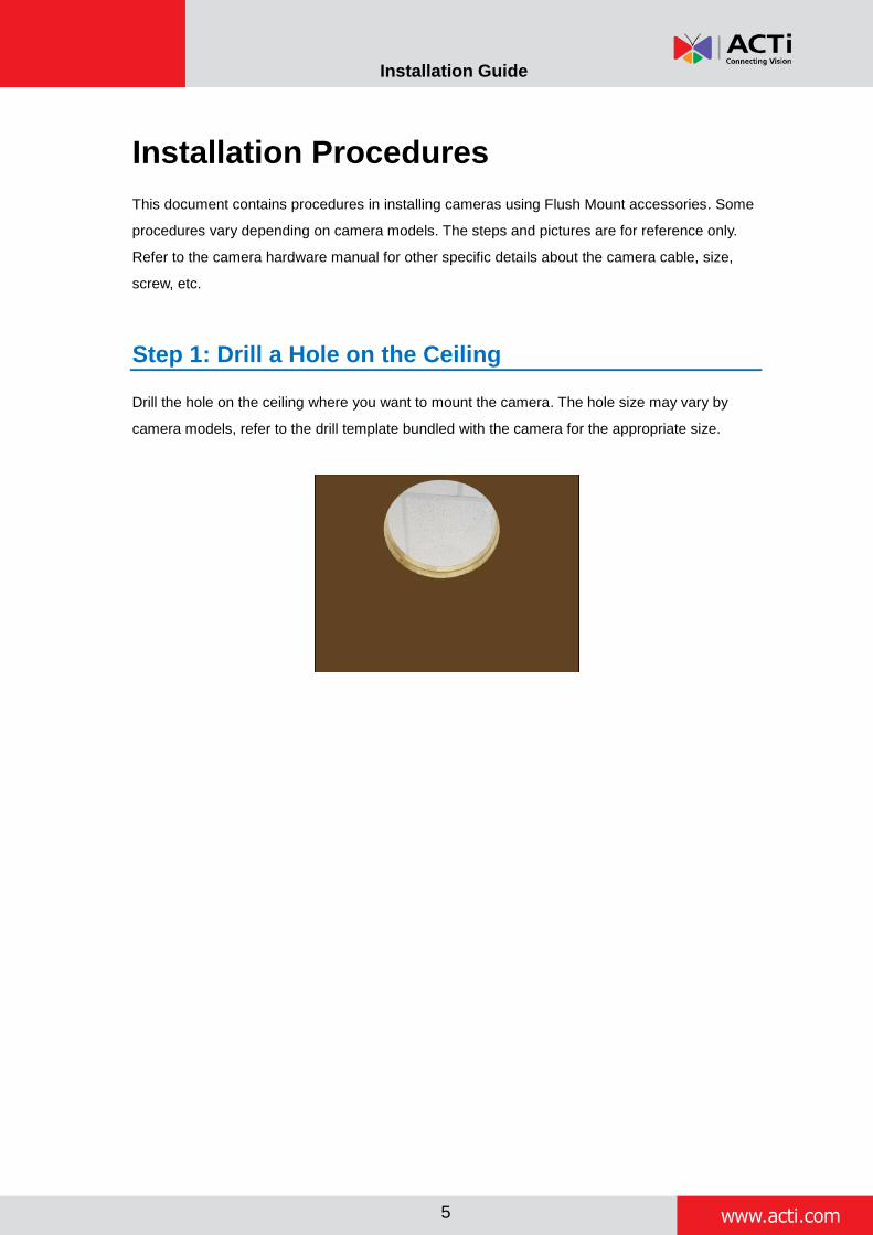
Step 1: Drill a Hole on the Ceiling
Drill the hole on the ceiling where you want to mount the camera. The hole size may vary by
camera models, refer to the drill template bundled with the camera for the appropriate size.

www.acti.com
Installation Guide
6
Step 2: Prepare for Waterproof Installation
NOTE: This section is applicable for outdoor dome cameras only.
The camera comes with two (2) glands used for waterproof installation:
Cable Gland: For use with an Exterior-grade Ethernet cable. Exterior-grade Ethernet
cables are already waterproof. See Waterproof Solution with Naked Cable on page 7.
Conduit Gland: For use with a flexible conduit. This solution is recommended when an
exterior-grade Ethernet cable is not available or when other input/output devices or
external power adapter will be connected to the camera (select models only). See
Waterproof Solution with Conduit on page 8.
Determine the type of waterproof solution that is applicable to your installation requirements and
prepare the necessary accessories or purchase extra materials.
Cable Gland Conduit Gland
For use with an Exterior-grade Ethernet
cable (not included in the package).
For use with a 3/8” flexible conduit (not included in the package).
For use with 1/2” flexible conduit (not included in the package)
NOTE: The bundled conduit gland may vary. Check the conduit gland that came with your package to determine if 3/8” or 1/2" is the suitable flexible conduit size.
or
www.acti.com
Installation Guide
7
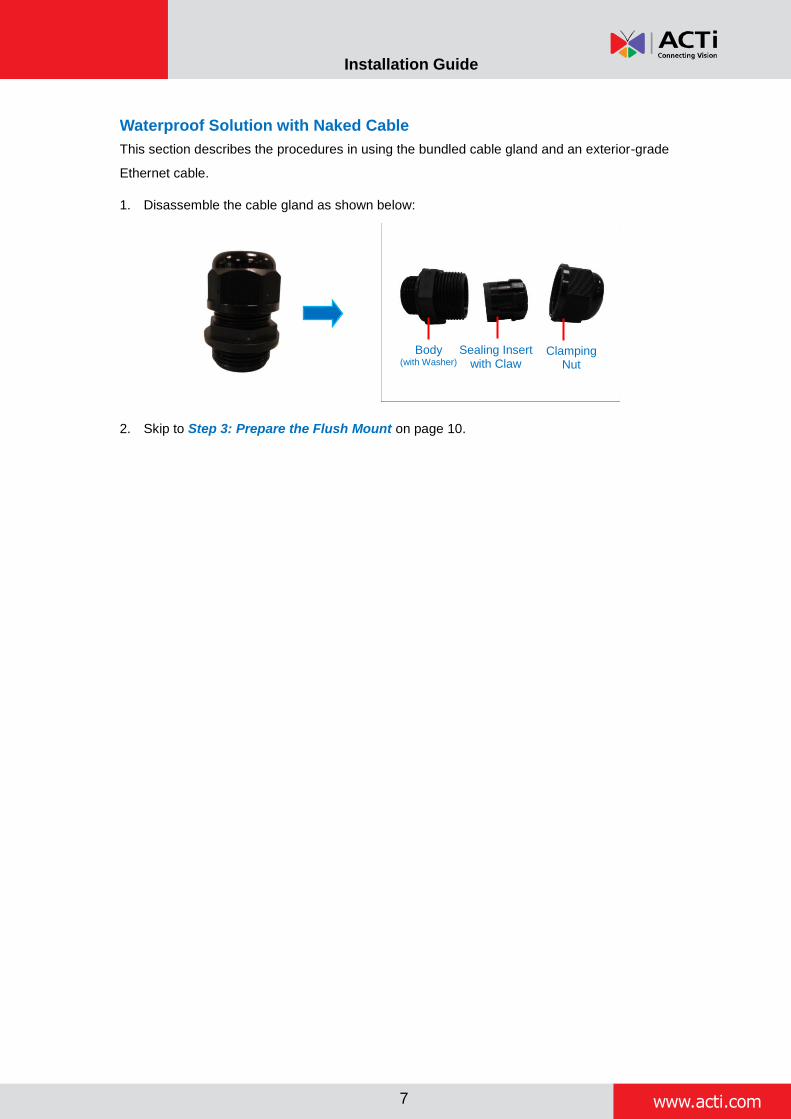
Waterproof Solution with Naked Cable
This section describes the procedures in using the bundled cable gland and an exterior-grade
Ethernet cable.
1. Disassemble the cable gland as shown below:
2. Skip to Step 3: Prepare the Flush Mount on page 10.
Body (with Washer)
Sealing Insert with Claw
Clamping Nut
www.acti.com
Installation Guide
8
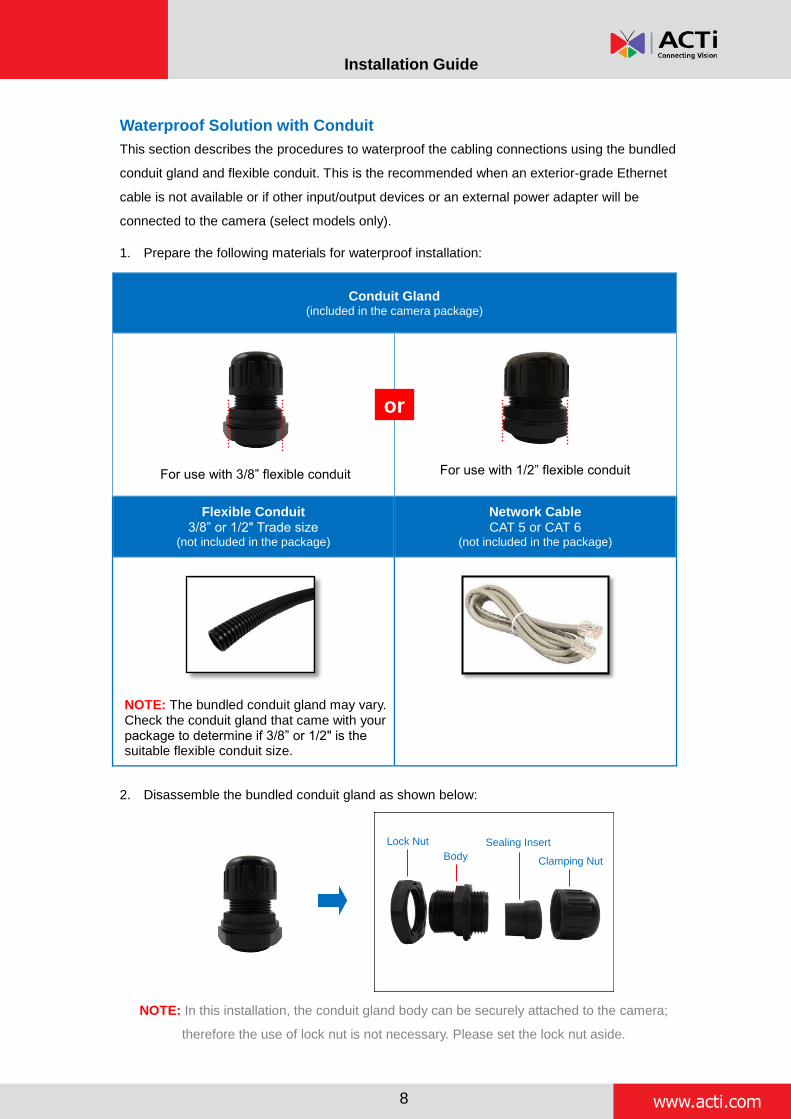
Waterproof Solution with Conduit
This section describes the procedures to waterproof the cabling connections using the bundled
conduit gland and flexible conduit. This is the recommended when an exterior-grade Ethernet
cable is not available or if other input/output devices or an external power adapter will be
connected to the camera (select models only).
1. Prepare the following materials for waterproof installation:
Conduit Gland (included in the camera package)
For use with 3/8” flexible conduit
For use with 1/2” flexible conduit
Flexible Conduit 3/8” or 1/2" Trade size
(not included in the package)
Network Cable CAT 5 or CAT 6
(not included in the package)
NOTE: The bundled conduit gland may vary. Check the conduit gland that came with your package to determine if 3/8” or 1/2" is the suitable flexible conduit size.
2. Disassemble the bundled conduit gland as shown below:
NOTE: In this installation, the conduit gland body can be securely attached to the camera;
therefore the use of lock nut is not necessary. Please set the lock nut aside.
Lock Nut
Body
Sealing Insert
Clamping Nut
or

www.acti.com
Installation Guide
9
3. Pull the network cable through the flex conduit.

www.acti.com
Installation Guide
10
Step 3: Prepare the Flush Mount
1. Route the flex conduit or network cable to dangle through the hole on the ceiling.
Using Flex Conduit Using Naked Cable
2. Peel off the lining of the three (3) foam rubber pads and attach a rubber pad to each
retaining bracket.
3. Using a screwdriver, loosen the retaining brackets according to the thickness of the ceiling.
or
www.acti.com
Installation Guide
11
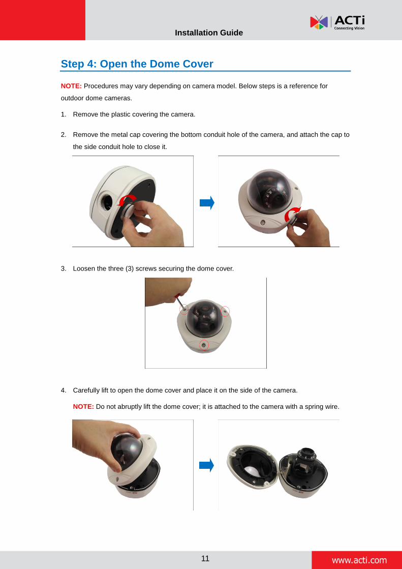
Step 4: Open the Dome Cover
NOTE: Procedures may vary depending on camera model. Below steps is a reference for
outdoor dome cameras.
1. Remove the plastic covering the camera.
2. Remove the metal cap covering the bottom conduit hole of the camera, and attach the cap to
the side conduit hole to close it.
3. Loosen the three (3) screws securing the dome cover.
4. Carefully lift to open the dome cover and place it on the side of the camera.
NOTE: Do not abruptly lift the dome cover; it is attached to the camera with a spring wire.

www.acti.com
Installation Guide
12
Step 5: Install the Camera
1. If necessary, insert a memory card (not supplied) into the card slot of the camera.
2. Align the screw holes and conduit hole of the camera to the mount.
3. Attach the three (3) screws (included in the flush mount package) to secure the camera to the
mount.
CAUTION: When using electric screwdrivers, be careful not to touch the internal
camera components while attaching the screws. Since electric screwdrivers vary in sizes,
speed, and force, they may bruise and damage the internal camera components.
DISCLAIMER: ACTi will not be responsible for camera damage caused by improper
installations or the misuse of equipment for installation.

www.acti.com
Installation Guide
13
Step 6: Connect the Cable(s)
For indoor models, simply connect the cable(s) to the camera connectors. Then skip to the next
section, Step 7: Install the Mount on page 17.
For outdoor dome cameras, you may refer to the procedures below for more details on cabling.
1. Tightly attach the gland body to the conduit hole of the camera.
2. Insert the clamping nut.
Using Flex Conduit Using Naked Cable
or

www.acti.com
Installation Guide
14
3. Insert the sealing insert. For flex conduit solution, attach the sealing insert at the end of the
flex conduit.
Using Flex Conduit
Using Naked Cable
4. Pull the network cable through the camera conduit hole.
Using Flex Conduit Using Naked Cable
NOTE: For camera models that support external power adaptor, audio in/out, or digital
input/output (DI/DO) functions, route the cables without connectors through the flex conduit
together with the network cable. Once cables pass through the conduit hole of the camera,
attach the bundled connectors.
or
www.acti.com
Installation Guide
15
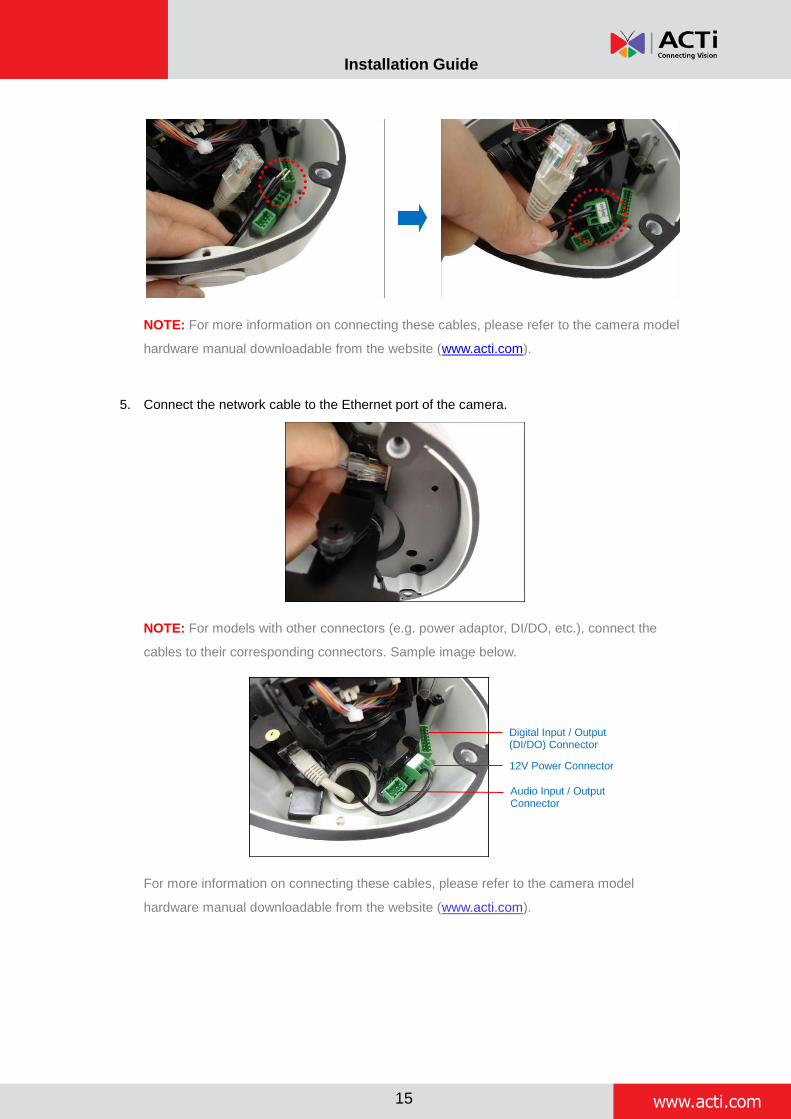
NOTE: For more information on connecting these cables, please refer to the camera model
hardware manual downloadable from the website (www.acti.com).
5. Connect the network cable to the Ethernet port of the camera.
NOTE: For models with other connectors (e.g. power adaptor, DI/DO, etc.), connect the
cables to their corresponding connectors. Sample image below.
For more information on connecting these cables, please refer to the camera model
hardware manual downloadable from the website (www.acti.com).
Digital Input / Output (DI/DO) Connector
12V Power Connector
Audio Input / Output Connector
www.acti.com
Installation Guide
16
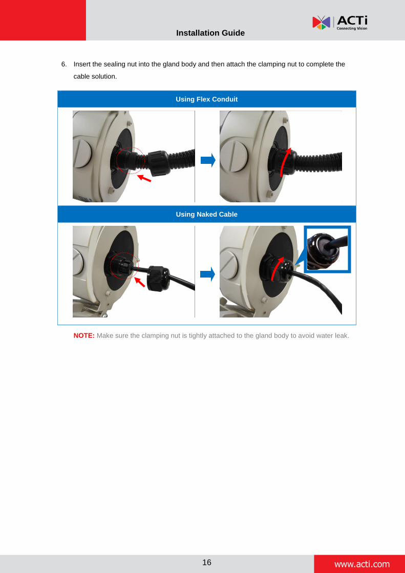
6. Insert the sealing nut into the gland body and then attach the clamping nut to complete the
cable solution.
Using Flex Conduit
Using Naked Cable
NOTE: Make sure the clamping nut is tightly attached to the gland body to avoid water leak.
www.acti.com
Installation Guide
17
Step 7: Install the Mount
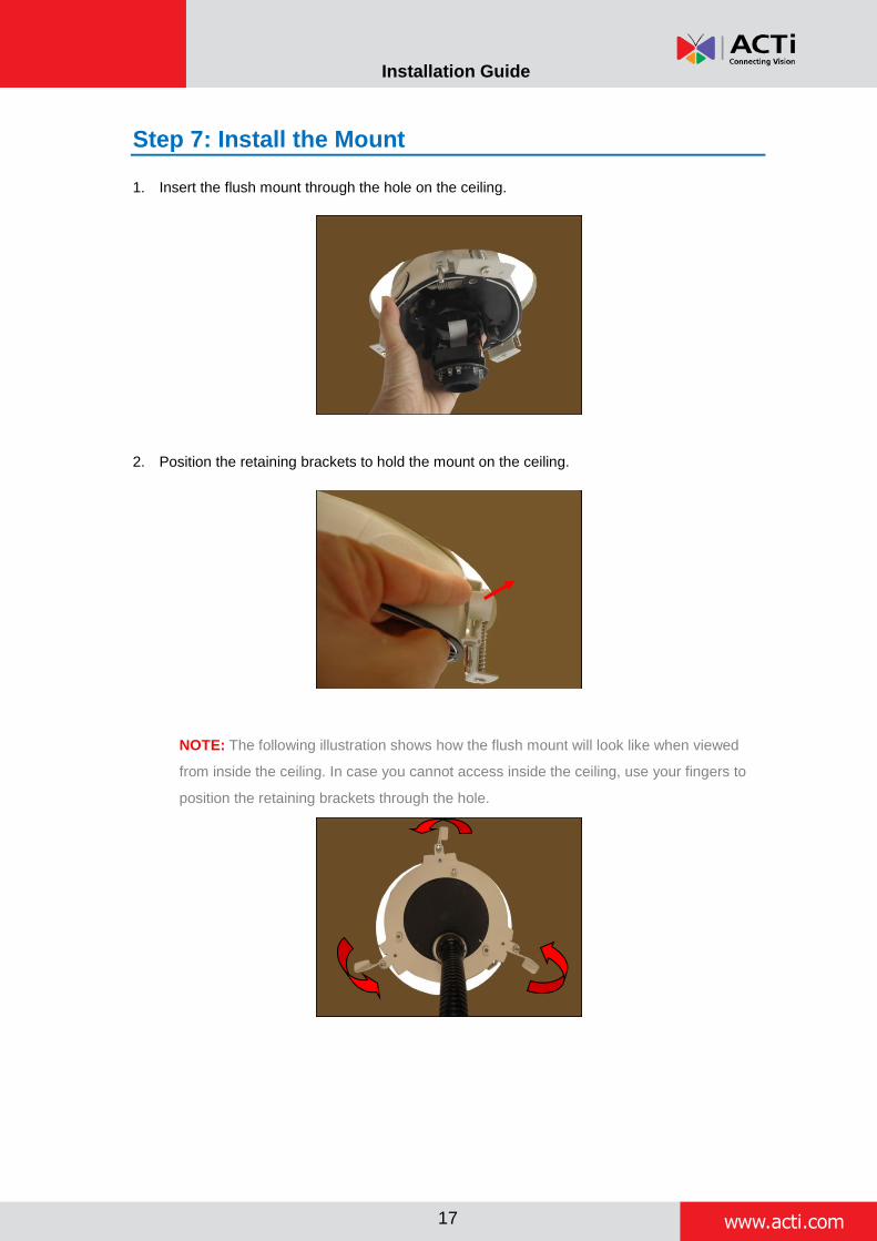
1. Insert the flush mount through the hole on the ceiling.
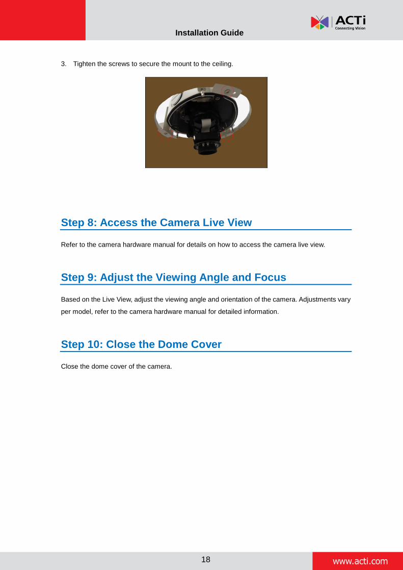
2. Position the retaining brackets to hold the mount on the ceiling.
NOTE: The following illustration shows how the flush mount will look like when viewed
from inside the ceiling. In case you cannot access inside the ceiling, use your fingers to
position the retaining brackets through the hole.
www.acti.com
Installation Guide
18
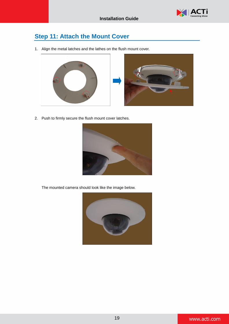
3. Tighten the screws to secure the mount to the ceiling.
Step 8: Access the Camera Live View
Refer to the camera hardware manual for details on how to access the camera live view.
Step 9: Adjust the Viewing Angle and Focus
Based on the Live View, adjust the viewing angle and orientation of the camera. Adjustments vary
per model, refer to the camera hardware manual for detailed information.
Step 10: Close the Dome Cover
Close the dome cover of the camera.
www.acti.com
Installation Guide
19
Step 11: Attach the Mount Cover
1. Align the metal latches and the lathes on the flush mount cover.
2. Push to firmly secure the flush mount cover latches.
The mounted camera should look like the image below.