installation, operation and maintenance manual files/thermal care fc series fibergla… ·...
TRANSCRIPT

Copyright 2010 Thermal Care Inc.
FC Series Fiberglass Cooling Towers
Installation, Operation and Maintenance Manual

Table of Contents FOREWORD ..................................................................................................................................................................1 INSTALLATION ..............................................................................................................................................................1
Receiving Inspection...................................................................................................................................................1 Fan Motor and Blade Assembly ...................................................................................................................................1 Rigging, Handling, and Locating Equipment ..................................................................................................................2 Piping ........................................................................................................................................................................2 Electrical Power .........................................................................................................................................................2
START-UP PROCEDURE ..................................................................................................................................................3 Pre-Start Cleaning ......................................................................................................................................................3 Trial Water Circulation................................................................................................................................................3 Trial Fan Operation ....................................................................................................................................................3
OPERATION AND MAINTENANCE...................................................................................................................................3 Fan Motor .................................................................................................................................................................3 Water Distribution .....................................................................................................................................................4 Seasonal Shutdown ....................................................................................................................................................4 Freeze Protection .......................................................................................................................................................4
OPTIONS ......................................................................................................................................................................4 Float Valve ................................................................................................................................................................4 Fan Motor Thermostat ...............................................................................................................................................4 Basin Heater Package .................................................................................................................................................4 Vibration Switch ........................................................................................................................................................5 Structural Steel Base & Legs ........................................................................................................................................5 Inlet Manifold ............................................................................................................................................................5 Inlet and Outlet Flanges ..............................................................................................................................................5 Equalization Connection .............................................................................................................................................5 Outlet Strainer ...........................................................................................................................................................5
CALCULATIONS .............................................................................................................................................................5 Evaporation Loss ........................................................................................................................................................5 Drift Loss ...................................................................................................................................................................5 Bleed-Off Rate ...........................................................................................................................................................5 Number of Concentrations .........................................................................................................................................5 Make-Up Water Required ...........................................................................................................................................6
DRAWINGS & CHARTS ...................................................................................................................................................7 Figure 1 – FC600 Series Fan Motor and Blade Assembly .............................................................................................7 Figure 2 – FC700 Series Fan Motor and Blade Assembly .............................................................................................8 Figure 3 – Support Steel Diagram .............................................................................................................................9 Figure 4 – FC600 Series Rigging Diagram ................................................................................................................ 10 Figure 5 – FC700 Series Rigging Diagram ................................................................................................................ 11 Figure 6 - FC600 Series General Specifications ........................................................................................................ 12 Figure 7 - FC700 Series General Specifications ........................................................................................................ 13
WARRANTY INFORMATION ........................................................................................................................................ 14
1
Foreword The intent of this manual is to serve as a guide for placing your cooling tower in service and operating and maintaining it properly. Improper installation can lead to poor equipment performance or severe equipment damage. Failure to follow the installation instructions may result in damage that will not be covered by your warranty. It is extremely important that a qualified installation contractor perform all installation line sizing and piping. Please supply these instructions to your authorized refrigeration contractor. This manual is supplemented as required to accommodate any special items that may have been provided for a specific application. The written information contained in this manual, as well as various drawings, are intended to be general in nature. The drawings included in this manual are typical only and may not represent the actual unit purchased. Drawings specifically applicable to each unit are included with the equipment and should be referred to for troubleshooting and servicing of the unit. Additional copies of drawings are available upon request. We strive to maintain an accurate record of all equipment during the course of its useful life. While every effort is made to standardize the design features of these chillers, the various options may make it necessary to rearrange some of the components; therefore, some of the general drawings in this manual may differ from your specific unit. Specific references to current applicable codes, ordinances, and other local laws pertaining to the use and operation of this equipment are avoided due to their ever-changing nature. There is no substitute for common sense and good operating practices when placing any mechanical equipment into operation. We encourage all personnel to familiarize themselves with this manual's contents. Failure to do so may unnecessarily prolong equipment down time. The cooling tower is designed for outdoor installation only. The use of untreated water in any cooling tower may cause serious health hazards, including the creation of conditions conducive to the development of Legionnella bacteria, which is known to cause Legionnaire's disease. A water treatment program to stop biological contamination must be used for all cooling tower installations in order to reduce such hazards. Do not operate this equipment without a proper water treatment program. Failure to follow these instructions could result in a hazardous condition. We recommend following good piping practices and the use of information in this manual. We cannot be held responsible for liabilities created by substandard piping methods and installation practices external to the chiller. We trust your equipment will have a long and useful life. If you should have any questions, please contact our Customer Service Department specifying the serial number and model number of the unit as indicated on the nameplate.
Installation
Receiving Inspection The cooling tower is skid mounted prior to shipment. Before accepting delivery, check the overall equipment condition for any visible damage. If damage is evident, it should be properly documented on the delivery receipt. Shipping damage is the responsibility of the carrier. In order to expedite payment for damages, it is important that proper procedures are followed and records kept. Photographs of damaged equipment are excellent documentation for your records. Once the packing is removed, the unit should be inspected for hidden damage. Check for broken lines, damaged controls, or any other major component torn loose from its mounting point. Any sign of damage should be recorded and a claim filed immediately with the shipping company. Our Customer Service Department will provide assistance in preparation and filing of your claims, including arranging for an estimate and quotation on repairs; however, filing the claim is the responsibility of the receiving party.
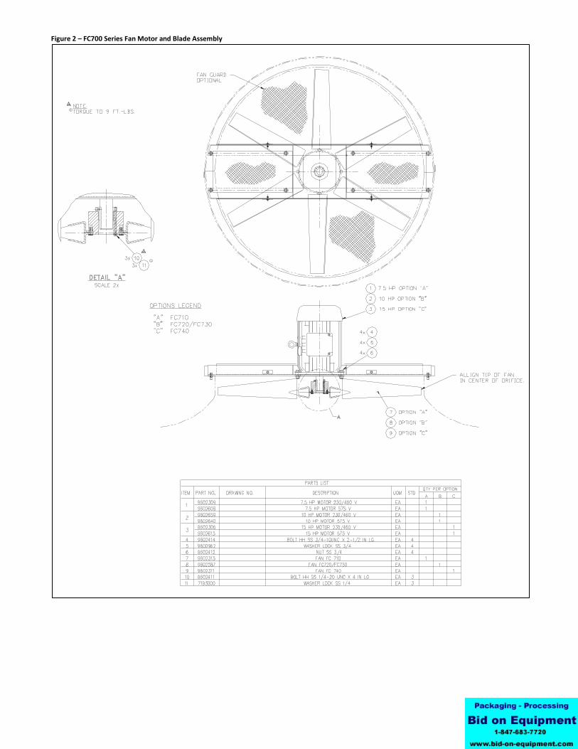
Fan Motor and Blade Assembly In order to prevent possible shipping damage, the fan motor and fan blade were removed prior to shipping. The motor support (and optional fan guards if purchased) shipped mounted on top of the tower. Please refer to the drawings at the back of this manual for fan motor and blade assembly details. Note: The cooling tower motor has condensation drain holes located on the shaft end of the motor to permit any moisture to drain out of the motor thereby extending motor life. The drain holes are 1/8 inch in diameter and depending on the motor vendor could be a simple open hole or will have an automatic drain device that looks like a hex head bolt with a hole drilled in the center. If any of the drain holes on the shaft end of the motor has a plastic shipping cap in them, remove them before installing the motor.
2
Use the following steps to install the fan motor and blade assembly:
1. Remove motor support frame (and optional fan guards if purchased) from top of tower. 2. Set the motor frame up off the ground (use saw horses or some other means of support). 3. Place the motor with the shaft pointing down onto the motor frame and bolt the motor to the frame using the
bolts provided. 4. Grease the shaft with Anti-seize or some other type of grease. Slide the split tapered bushing onto the motor shaft
with the shoulder of the bushing facing towards the motor. The bottom of the bushing should be flush with the end of the motor shaft.
5. Slide the tower fan (the top of the fan has the aluminum spool attached to it) over the split tapered bushing. 6. Line up the non-threaded holes of the fan spool with the threaded holes in the split tapered bushing. 7. From the underside of the fan, insert the 1/4" x 4" bolts with lock washers provided through the non-threaded
holes in the fan and screw them into the split tapered bushing. The bushing should still be flush with the end of the motor shaft.
8. Tighten up the bolts in a uniform pattern until the fan is locked onto the fan bushing. Once the bolts are tight, the fan bushing should still be flush with the end of the motor shaft.
9. Remount the entire fan motor and fan assembly (and optional fan guards if purchased) back on top of the cooling tower.
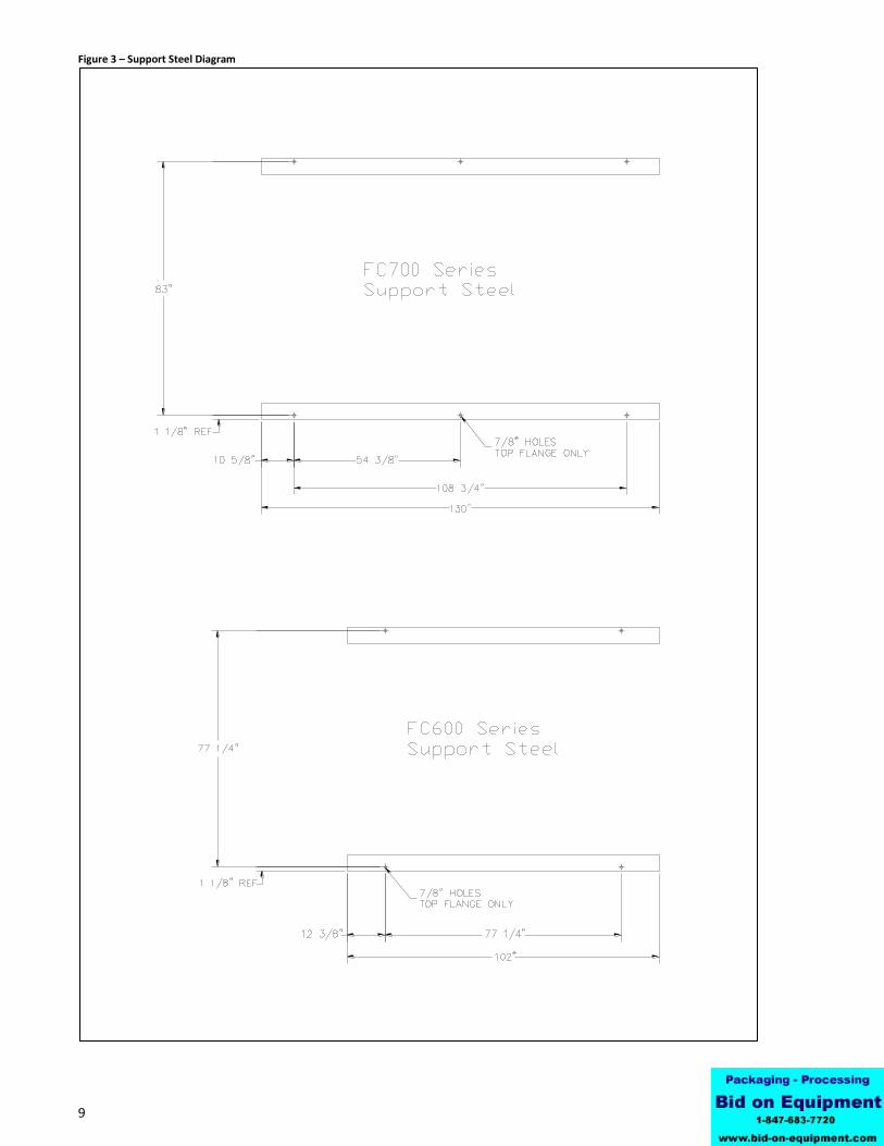
Rigging, Handling, and Locating Equipment Proper rigging methods must be followed to prevent damage to components. Avoid impact loading caused by sudden jerking when lifting or lowering the chiller. Use pads where abrasive surface contact is anticipated. It is highly recommended that spreader bars be used. Keep rigging clear of inlet piping. Do not use the motor support for lifting the cooling tower. The location of the cooling tower must be outdoors and depends on such considerations as space, proximity to walls and other equipment, accessibility, and serviceability. Above all, it is important that air intake is not hindered or affected by heat and/or humidity producing devices. The discharge air must be allowed to flow upwards without obstruction. The cooling tower is designed to be mounted on two parallel 8 inch I-beams. Prefabricated steel support frames are an available option or can be fabricated on-site. Please refer to the drawings at the back of this manual for support frame details.
Piping The tower is equipped with PVC piping and the connections are not designed to support the weight of the external piping. Inspect water spray nozzles when installing connecting piping to the tower inlet lines. This inspection should be done through the access door on the side and through the top of the cooling tower. All spray nozzles must be oriented in a fully vertical position to ensure proper water distribution through the tower. These should be adjusted before final connections are made to the tower. The cooling tower is supplied with PVC pipe stub connections. Optional inlet and outlet flanges are available. Some form of flow control, such as a butterfly valve and inlet pressure gauge, are required to assure the pressure and flow through the tower do not exceed the ratings of the tower as shown in Figures 6 and 7 at the back of this manual. Where climates reach freezing temperatures, be sure the supply line to the tower is able to drain when the pump shuts off.
Electrical Power All wiring must comply with local codes and the National Electric Code. Minimum Circuit Ampacities (MCA) and other unit electrical data are on the unit nameplate. The cooling tower is designed to operate with a specific voltage and frequency and can operate with voltages ± 10% of that design with a supply frequency of ± 5% and with a maximum voltage imbalance between the legs of 2%. Using a supply voltage/frequency at or beyond these range limits will cause a unit fault. Voltage imbalance is determined using the following calculations:
%Imbalance = (Vavg – Vx) x 100 / Vavg
Vavg = (V1 + V2 + V3) / 3
Vx = phase with greatest difference from Vavg
3
For example, if the three measured voltages are 442, 460, and 454 volts, the average would be:
(442 + 460 + 454) / 3 = 452 The percentage of imbalance is then:
(452 – 442) x 100 / 452 = 2.2 % This exceeds the maximum allowable of 2%. If the measured voltage on any leg is not within the specified range, notify the supplier and correct before operating the unit.
Start-Up Procedure
Pre-Start Cleaning Once the tower has been completely assembled and placed, make sure all disconnects are locked out. Remove one of the inlet louver sections. Open the drain and flush the basin with water to remove any remaining dirt and debris from basin. Check all fasteners to make sure there are no loose components.
Trial Water Circulation Fill the circulation system with water. If the basin of the cooling tower is fitted with a make-up, fill the system until the make-up valve is closed. Check tower basin and connections for leaks. Close discharge valves of pumps completely. Check rotation of tower pumps by starting them momentarily. Once proper pump rotation is established, slowly open each pump discharge valve to 1/4 open and run the pumps for about five minutes to make sure all air has been removed from the system. Stop pumps and check tower outlet to make sure it is still clean and free from debris. Check water level in the system again to make sure system is still full. Start pumps again. While pumps are running, set the flow to the tower by adjusting the discharge valves of the pumps. After steady water flow is established, adjust tower inlet valves to proper pressure to allow for design flow referring to the Inlet Pressure/Flow Charts at the back of this manual. Stop the pumps and lock out disconnects until ready to start system.
Trial Fan Operation Lock out all disconnects before servicing any portion of the tower. Check for smooth operation and clearance between blades and tower by manually turning the fan blade. Clear the air intake and discharge areas of any foreign material. Check the power supply for correct voltage, frequency, and phase. Turn on fan motor for a moment to check fan rotation to confirm fan will properly discharge air out of top of tower. If the fan is rotating in the wrong direction, turn off fan motor, wait for fan to stop, and lock out disconnect. Rewire fan motor, by switching any two power leads. Once proper rotation has been established, operate the fan motor and check the amp draw to verify that it falls within the nameplate rating. If amp draw is in excess of the nameplate amps, call the Customer Service Department for assistance. Continue to operate the fan motor for two or three hours. If abnormal vibration or sound develops, disconnect power and contact the Customer Service Department for assistance. Stop fan motor and lock out disconnects until ready to start the system. Check all fan bolts to assure they are tight.
Operation and Maintenance
Fan Motor The motor should bring the fan up to full speed in less than five seconds. If it does not, check connections, fuses, overloads, and voltage at the motor terminals. If everything does not properly check out, call the Customer Service Department for assistance.
CAUTION: Do not cycle a motor on and off more than necessary. Frequent cycling may cause the windings to burn out. Generally, the total of the starting times should not exceed 12 starts per hour. When changing fan direction, allow a minimum of two minutes before reenergizing the motor.
4
CAUTION: If vibration occurs, shut the fan off immediately. Check the motor mounting and make sure all fasteners are tight. If everything is tight, remove fan blade assembly from motor and start without the fan blade. If the motor vibrates, contact the Customer Service Department for instructions. If the vibration is not in the motor, check the alignment of motor with mechanical equipment and the balance of the fan blade. Make sure all fan blades are secure and complete. If source of vibration cannot be isolated, contact the
Customer Service Department for assistance. An optional vibration switch wired in series with the fan motor contactor will protect the tower from potential damage caused by vibration.
Water Distribution Scale or sludge buildup will impede the proper operation of the spray nozzles. If the spray pattern slows or stops, check the water flow to make sure it is correct. If it is not correct, dismantle and clean the nozzles by twisting the nozzle and pulling downward. Clean nozzles with plastic bottle brush and cleaning solution. Do not soak nozzle in cleaning solution. Only use a cleaning solution with a pH of 3.0 or greater.
Seasonal Shutdown If the tower will be shutdown during the winter, it is recommended that the motor be run for three hours a month to keep the bearings lubricated and the windings dry. Be sure to inspect motor before bringing it back into full operation. Check basin for debris, clean if required. Inspect fill for contamination, change fill if needed.
Freeze Protection When cooling towers are subjected to intermittent shutdown (nights, weekends, etc.) during cold weather, or when operating against minimum loads, the opportunity for freezing of the water contained in the water basin and internal piping within the tower exists. Maintain freedom of fan rotation. Do not operate if snow, ice, or other obstructions will interfere with fan rotation. An indoor auxiliary sump is the best means of avoiding tower freeze-up. With a properly piped remote sump system the water within the tower basin and internal piping of the tower is allowed to drain to the indoor sump whenever the recirculation water pump is stopped. Where a remote sump is impractical because of tower location or space limitation, heat must be supplied to the water in the tower basin through the use of electric immersion heaters. Basin heater packages are available.
Options
Float Valve This option includes float valve bulkhead fitting, plugged drain connection, and overflow fitting. The float valve threads into the bulkhead fitting in the basin of the cooling tower. The bulkhead fitting is not installed unless the float valve option is ordered. To install, hand tighten the valve with the discharge pointing down. Establish basin water level by loosening wing nut at the pivot point, adjust float arm and retighten until the water level rises 2 inches below the overflow. Note: If water supply pressure is above 50 PSI, the float may not be able to shut off the make-up valve. This requires installation of a pressure reducing valve in the water supply line.
Fan Motor Thermostat This option includes a ship loose thermostat to be mounted in the field piping for the purpose of cycling the cooling tower fan and/or pump to maintain the cooling tower return water temperature during changing load or ambient temperature conditions. See the suggested electrical wiring diagram at the back of this manual for reference.
Basin Heater Package For applications in climates subjected to occasional freezing temperatures, basin heaters can prevent water in the tower basin from freezing. The basin heater package includes two heaters, thermostat and low level cutoff switch. See the suggested electrical wiring diagram at the back of this manual for reference. Note: Electric basin heaters will not protect exposed supply and return water piping. Such piping, as well as the exposed make-up water line, must be separately heat traced and insulated. It is not normally necessary to protect horizontal piping at the top of the tower since it is usually self-draining into the tower. Risers above the level of the cold water basin can be protected by simply installing a small bypass line from the riser to the cold water basin to permit back draining.
5
Vibration Switch This option includes a ship loose vibration switch which is designed to protect the tower by shutting off the fan if excessive vibration develops.
Structural Steel Base & Legs The structural steel base is designed to elevate the tower with four steel legs. The legs weld directly to the steel base and include cross bracing as required for structural stability. Tower legs are available up to 20 feet in length. Refer to the drawings at the back of this manual for specifications and dimensions of base and legs.
Inlet Manifold This option is for larger cooling towers with two inlet pipe connections and includes a manifold to tie the two inlets together as well as a 6" butterfly valve and pressure gauge with a 6 inch flange connection to be connected to the supply water piping.
Inlet and Outlet Flanges As standard the cooling tower is provided with plain end PVC pipe stub connections. This option provides 125 # flanged connections to the inlet and outlet water connections.
Equalization Connection When more than one tower is used on an installation, without a remote sump, the overflow point of all towers should be at the same level to prevent a tower from flooding. In addition, we recommended all towers basin connected together into one common return water line include an equalization connection to connect the basins together to assure a consistent operating level between all tower basins.
Outlet Strainer A 304 stainless steel outlet strainer is available to prevent debris from entering the tower system. The strainer can be accessed by removing a louver section and loosening the bolts holding the strainer to the outlet connection.
Calculations
Evaporation Loss If exact evaporation losses are not known, an approximation can be obtained by using the following formula (see ASHRAE Equipment 1992, 39.11):
Evaporative Loss (GPM) = Range x GPM x .0008 Range = water in (°F) less water out (°F) GPM = gallons of water per minute through the tower
Drift Loss Drift loss can be approximated from the equation below which assumes a loss of .02% of the water flowing through the tower.
Drift Loss (GPM) = GPM x .0002
Bleed-Off Rate The bleed-off rate required is dependent on the condition of the makeup water and the number of concentrations desired. The bleed-off rate should therefore be calculated by the company providing the water treatment equipment.
Number of Concentrations The number of concentrations present in the system is the measure of how concentrated the level of dissolved solids in the water.
Number of = Evaporation + Drift + Bleed-Off Concentrations Drift + Bleed-Off
6
Make-Up Water Required The amount of make-up water required is dependent on a number of factors
Make-up water required (GPM) = E + D + B E = Evaporative Loss in Gallons per Minute D = Drift Loss in Gallons per Minute B = Bleed-Off Rate in Gallons per Minute

7
Drawings & Charts Figure 1 – FC600 Series Fan Motor and Blade Assembly
8
Figure 2 – FC700 Series Fan Motor and Blade Assembly
9
Figure 3 – Support Steel Diagram

10
Figure 4 – FC600 Series Rigging Diagram

11
Figure 5 – FC700 Series Rigging Diagram
12
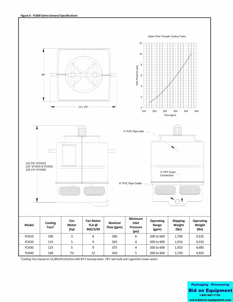
Figure 6 - FC600 Series General Specifications
Model Cooling Tons
1
Fan Motor
(hp)
Fan Motor FLA @
460/3/60
Nominal Flow (gpm)
Minimum Inlet
Pressure (psi)
Operating Range (gpm)
Shipping Weight
(lbs)
Operating Weight
(lbs)
FC610 100 3 6 300 6 200 to 600 1,760 4,535
FC620 115 5 9 345 4 200 to 600 1,910 4,535
FC630 125 5 9 375 4 200 to 600 1,910 4,685
FC640 140 7½ 12 420 5 200 to 600 2,150 4,925
1Cooling Tons based on 15,000 BTU/Hr/ton with 85°F leaving water, 78°F wet bulb and 3 gpm/ton tower water.
2" FPT Drain
Connection
122 3/4" (FC610)
125" (FC620 & FC630)
128 1/4" (FC640)
90"
111 1/4"
4" PVC Pipe Inlet
8" PVC Pipe Outlet
Water Flow Through Cooling Tower
0
2
4
6
8
10
12
150 250 350 450 550 650
Flow (gpm)
Inle
t P
ressure
(psi)

13
100 1/2"
139 1/2"
124 1/2" (FC710)
127 1/2" all others
4" PVC
Pipe Inlets
8" PVC
Pipe Outlet
2" FPT Drain
Connection
Figure 7 - FC700 Series General Specifications
Model Cooling Tons
1
Fan Motor
(hp)
Fan Motor FLA @
460/3/60
Nominal Flow (gpm)
Minimum Inlet
Pressure (psi)
Operating Range (gpm)
Shipping Weight
(lbs)
Operating Weight
(lbs)
FC710 170 7½ 12 510 5 350 to 725 2,660 5,230
FC720 185 10 17 555 6 350 to 725 2,700 5,530
FC730 205 10 17 615 7 350 to 725 2,700 5,570
FC740 240 15 24 720 10 350 to 725 2,750 5,570
1Cooling Tons based on 15,000 BTU/Hr/ton with 85°F leaving water, 78°F wet bulb and 3 gpm/ton tower water.
Water Flow Through Cooling Tower
0
2
4
6
8
10
12
300 400 500 600 700 800
Flow Through Cooling Tower (gpm)
Inle
t P
ressure
(p
si)