installation operation and maintenance instructions … · 6.2 flra – rotate the adjustable...
TRANSCRIPT

1
INSTALLATION OPERATION AND MAINTENANCE INSTRUCTIONS EXHEAT
INDUSTRIAL FLR & FLRA TYPE FLAMEPROOF RADIATORS
Please read these instructions thoroughly before installation and ensure they
are passed on to the end-user

2

3
CONTENTS
1.0 GENERAL 4
2.0 STORAGE 4
3.0 INSTALLTION 5
4.0 ELECTRICAL SUPPLY CONNECTION 5
5.0 EARTH CONNECTION 6
6.0 OPERATION 6
7.0 MAINTENANCE 6
8.0 MARKING 7
9.0 CERTIFICATION 7
APPENDIX A – WIRING DIAGRAM 8
APPENDIX B – HEATER GENERAL ARRANGEMENT DIAGRAM 9
APPENDIX C – CAGE GENERAL ARRANGMENT DIAGRAM 10
APPENDIX D – ATEX HAZARDOUS AREA CERTIFICATE
To maintain the equipment warranty and the Hazardous Area Certification, the instructions contained within this manual must be complied with in full.

4
1.0 GENERAL
1.1 All work should be carried out by suitably qualified personnel.
1.2 Equipment must be handled with care and stored in dry conditions.
1.3 CAUTION – these radiators are heavy and must be handled appropriately:
50kg FLR1
100kg FLR2
150kg FLR3
1.4 Carefully remove all protective packaging and visually inspect unit for any transit damage.
1.5 All prevailing rules, regulations and bylaws in force at the time and place of installation must be observed.
1.6 Any modification not carried out by Exheat Industrial Ltd will invalidate certification and warranty.
1.7 This is a hazardous area heater. Reference must be made to EN 60079-17 & IEC 1241-1-2.
1.8 All electrical testing must be carried out in a non-hazardous area.
1.9 Precautions must be taken to prevent damage to machined surfaces and threads of flameproof enclosures.
1.10 Ensure that any special conditions for safe use detailed on the hazardous area certification are complied with.
1.11 CAUTION – the liquid within the radiator contains glycol and must not be consumed. Should a leak occur the heater must be de-energised immediately and returned to Exheat Industrial Ltd for repair. Any leaks must be cleared up with care and hands washed immediately after contact.
2.0 STORAGE
2.1 Store the equipment in an inside location that is dry, clean and well ventilated.
2.2 Suitable preservation materials, such as silica gel bags or equivalent, have been placed inside the packaging. Additionally, spare silica gel bags, or equivalent, can be supplied by contacting Exheat Industrial Ltd.
2.3 If the equipment is stored beyond 3 months, ensure that preservation materials are replaced.
2.4 CAUTION – It is the client’s responsibility to ensure that, if the terminal enclosure is opened prior to installation, these bags are checked and replaced if necessary. When refitting terminal enclosure lid refer to 4.8 below.
2.5 CAUTION – The following preservation instructions must be adhered to. Failure to do so could result in the equipment warranty being invalidated:
Store the equipment at between 0°C and +50°C. Ensure that the equipment is not subjected to direct sunlight at ambient temperatures
above 30°C.

5
3.0 INSTALLATION
3.1 Carefully remove the packaging from each item and check for damage. Immediately report any damage to Exheat Industrial Ltd.
3.2 Move the equipment by either crane or fork lift truck, using suitable rated lifting slings to prevent damage.
All lifting tackle/equipment must have a safe working load (SWL) capacity in excess of that of the equipment weight and include for snatch factors etc.
The slings or ropes must be long enough to keep the angle between the slings/ropes and the top of the equipment greater than 90°
Ensure that the destination position is free from obstructions. Move the equipment into position and set the load down carefully and without
bumping.
3.3 The radiator should be securely fixed in position with the wall brackets supplied and all terminal connections checked for tightness before energising. Please refer to APPENDIX B & C for all mounting point dimensions.
3.4 The correct installed orientation is with the terminal box at the bottom of the radiator.
3.5 The installer or end user shall ensure that the unit has free and unrestricted air flow to allow natural convection to occur at all times. DO NOT COVER the radiator and do not allow anything to rest on or against it. If a protective guard is required, only Exheat Industrial Ltd’s design is pre-approved and tested with the FLR range.
3.6 At no time is the ambient temperature to be allowed to rise above 40°C.
3.7 FLRA radiators supplied with an externally adjustable thermostat must be limited and set to a maximum of 25°C.
4.0 ELECTRICAL SUPPLY CONNECTION
4.1 Refer to wiring diagram APPENDIX A.
4.2 The cable entry is positioned on the bottom of the terminal box.
4.3 Before connection ensure that the supply corresponds with that specified on the rating label.
4.4 Ensure that the sizes and types of cables to be used are suitably rated for the load and temperature of the unit.
4.5 Each heater must be protected by a suitably rated over current device and earth leakage circuit breaker device. See section 5 below for earthing details.
4.6 The cables must enter the heater terminal box via suitably certified cable glands (not supplied) and be fitted by a qualified person. Any unused entries should remain plugged with the factory fitted certified Ex d plugs.
4.7 The cover of the terminal box is removed after releasing the 3 socket head screws in the cover. When re-fitting ensure that the ‘o’ ring seal is in good condition and correctly located. The main cover mating and spigot faces MUST be kept clean and free from any debris at all times.
4.8 After re-fitting, the gap between the cover and the body must be checked to ensure that it does not exceed 0.15mm.
4.9 The installer or end user must connect to the Exheat Industrial Ltd supplied terminals within the terminal box - DO NOT connect to or disturb factory fitted wiring.
4.10 WARNING – Silica gel bags must be removed before the heater is energised.
6
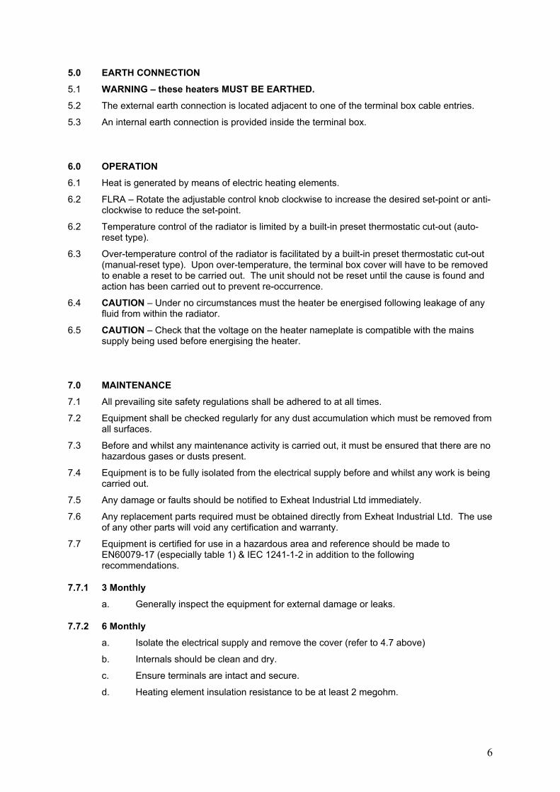
5.0 EARTH CONNECTION
5.1 WARNING – these heaters MUST BE EARTHED.
5.2 The external earth connection is located adjacent to one of the terminal box cable entries.
5.3 An internal earth connection is provided inside the terminal box.
6.0 OPERATION
6.1 Heat is generated by means of electric heating elements.
6.2 FLRA – Rotate the adjustable control knob clockwise to increase the desired set-point or anti-clockwise to reduce the set-point.
6.2 Temperature control of the radiator is limited by a built-in preset thermostatic cut-out (auto-reset type).
6.3 Over-temperature control of the radiator is facilitated by a built-in preset thermostatic cut-out (manual-reset type). Upon over-temperature, the terminal box cover will have to be removed to enable a reset to be carried out. The unit should not be reset until the cause is found and action has been carried out to prevent re-occurrence.
6.4 CAUTION – Under no circumstances must the heater be energised following leakage of any fluid from within the radiator.
6.5 CAUTION – Check that the voltage on the heater nameplate is compatible with the mains supply being used before energising the heater.
7.0 MAINTENANCE
7.1 All prevailing site safety regulations shall be adhered to at all times.
7.2 Equipment shall be checked regularly for any dust accumulation which must be removed from all surfaces.
7.3 Before and whilst any maintenance activity is carried out, it must be ensured that there are no hazardous gases or dusts present.
7.4 Equipment is to be fully isolated from the electrical supply before and whilst any work is being carried out.
7.5 Any damage or faults should be notified to Exheat Industrial Ltd immediately.
7.6 Any replacement parts required must be obtained directly from Exheat Industrial Ltd. The use of any other parts will void any certification and warranty.
7.7 Equipment is certified for use in a hazardous area and reference should be made to EN60079-17 (especially table 1) & IEC 1241-1-2 in addition to the following recommendations.
7.7.1 3 Monthly
a. Generally inspect the equipment for external damage or leaks.
7.7.2 6 Monthly
a. Isolate the electrical supply and remove the cover (refer to 4.7 above)
b. Internals should be clean and dry.
c. Ensure terminals are intact and secure.
d. Heating element insulation resistance to be at least 2 megohm.

7
e. Refit cover with new gasket or ‘o’ ring if required (refer to 7.6 above) and re-tighten using only the socket head screws provided.
f. Check the flamepath gap as 4.8 above.
g. Earth continuity must be maintained between all earth points and main structure.
7.7.3 Annually
a. Carry out 3 monthly and 6 monthly checks as above.
b. Check for element failure or low insulation resistance.
7.8 Only Exheat Industrial Ltd can carry out rod type element replacements in hazardous area heaters, any unauthorised modifications will invalidate the hazardous area certification and any warranty.
7.9 If equipment is being left unused for a period greater than 3 months, carry out 6 monthly maintenance before energizing.
7.10 Should a leak occur, the heater must be de-energised immediately and returned to Exheat Industrial Ltd for repair. Any leaks must be cleared up with care and hands washed immediately after contact.
8.0 Marking
8.1 II 2 G D
Ex d IIC T6 Gb
Ex t IIIC T85°C Db
IP6X
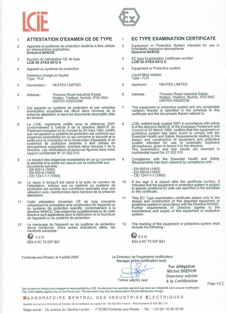
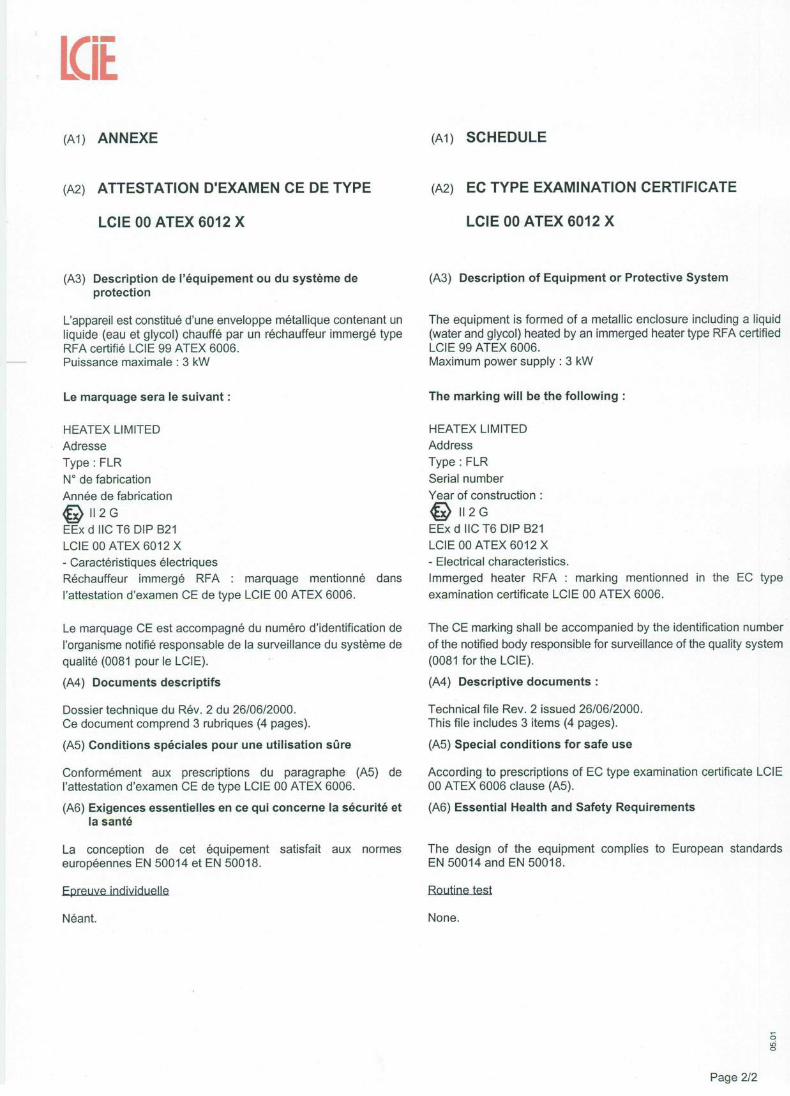
9.0 Certification
9.1 LCIE 00 ATEX 6012 X
8
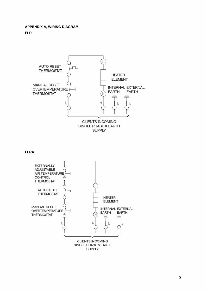
APPENDIX A, WIRING DIAGRAM
FLR
FLRA

9
APPENDIX B, HEATER GENERAL ARRANGMENT DIAGRAM
MODEL STOCK CODE
kW DIMENSIONS (mm) WEIGHT
‘A’ ‘B’ ‘C’ ‘D’ KG
FLR1 S63030001 1 580 510 n/a n/a 50
FLR2 S63030002 2 1130 1035 510 550 100
FLR3 S63030003 3 1680 1575 780 830 150
FLR1A S63040001 1 580 510 n/a n/a 50
FLR2A S63040002 2 1130 1035 510 550 100
FLR3A S63040003 3 1680 1575 780 830 150

10
APPENDIX C, CAGE GENERAL ARRANGMENT DIAGRAM
MODEL STOCK CODE DIMENSIONS (mm) WEIGHT
‘A’ ‘B’ KG
FLR1 S63050001 795 835 25
FLR2 S63050002 1280 1320 33
FLR3 S63050003 1820 1860 44

11


12
EXHEAT INDUSTRIAL LTD Threxton House, Threxton Road Industrial Estate
Watton, Thetford, IP25 6NG Tel: +44 (0)1953 886210 Fax: +44 (0)1953 883853
For sales and new product information see our website www.exheat-industrial.com
2006/95/EC 89/336/EEC
(As amended by 92/31/EEC & 93/68/EEC) 94/9/EC
Stock Code S090.00.0000.0018 Issue 7