installation protective relay maintenance hardware … the instantaneous overcurrent function ......
TRANSCRIPT

Manual No. SG-9228-02
InstructionInstallationOperationMaintenance
Hardware 3.11Software 3.40
SCOR OvercurrentProtective Relay
Phase
Tap TapA AB BC C
D DE EF F
G G
H H
I I
J JA B C
High
Ground
Function / DataTmg
StatusMode Up
Next Down
Low
Style H1E Z5J B1COS
SCOR
Power
Tap A B C D E F G H I J
High
Low
2.0
0.5
3.0
1.0
4.0
1.5
5.0
2.0
6.0
2.5
7.0
3.0
8.0
3.5
9.0
4.0
10.0
4.5
11.0
5.0
FunctionPush toenergizeoutput
l1
TT Time Inst. 1
Element
A B C G
TargetReset
The use of unauthorized parts in the repair of the equipment or tamperingby unqualified personnel will result in dangerous conditions which willcause severe personal injury or equipment damage. Follow all safetyinstructions contained herein.
IMPORTANTThe information contained herein is general in nature and not intended forspecific application purposes. It does not relieve the user of responsibilityto use sound practices in application, installation, operation, and mainte-nance of the equipment purchased. Siemens reserves the right to makechanges in the specifications shown herein or to make improvements atany time without notice or obligations. Should a conflict arise between thegeneral information contained in this publication and the contents ofdrawings or supplementary material or both, the latter shall take prece-dence.
QUALIFIED PERSONFor the purpose of this manual a qualified person is one who is familiar withthe installation, construction or operation of the equipment and thehazards involved. In addition, he has the following qualifications:(a) is trained and authorized to de-energize, clear, ground, and tag
circuits and equipment in accordance with established safetypractices.
(b) is trained in the proper care and use of protective equipment suchas rubber gloves, hard hat, safety glasses or face shields, flashclothing, etc., in accordance with established safety practices.
(c) is trained in rendering first aid.
SUMMARYThese instructions do not purport to cover all details or variations in equipment, nor to provide for every possible contingencyto be met in connection with installation, operation, or maintenance. Should further information be desired or shouldparticular problems arise which are not covered sufficiently for the purchaser’s purposes, the matter should be referred tothe local sales office.
The contents of this instruction manual shall not become part of or modify any prior or existing agreement, commitmentor relationship. The sales contract contains the entire obligation of Siemens Energy & Automation, Inc. The warrantycontained in the contract between the parties is the sole warranty of Siemens Energy & Automation, Inc. Any statementscontained herein do not create new warranties or modify the existing warranty.

Table of Contents
1. General ................................................... 11.1 Description.................................................................. 1
1.2 Application .................................................................. 1
1.3 The Time Overcurrent Function................................... 1
1.3.1 Pickup.................................................................... 1
1.3.2 Timing .................................................................... 1
1.3.3 Trip and Reset ....................................................... 1
1.4 RMS Sensing .............................................................. 1
1.5 The Instantaneous Overcurrent Function(Option 1-1) ........................................................... 2
1.6 The Ground Time Overcurrent andInstantaneous Functions ........................................ 2
1.7 Ground Trip Selectivity ................................................ 2
1.8 Auxiliary Output Relay (Option 1-2) ............................. 3
1.9 Communications Option ............................................. 3
1.9.1 The Ports ............................................................... 3
1.9.2 Communications .................................................... 3
1.10 Breaker Failure .......................................................... 4
1.11 Style Number (Figure 2) ............................................ 4
1.12 Time Overcurrent Characteristic Curves ................... 5
1.13 Instantaneous OvercurrentCharacteristic Curves ............................................ 5
2. Controls and Indicators ........................ 62.1 General ....................................................................... 6
3. Operation by Front Panel ................... 103.1 General ..................................................................... 10
3.2 The Configuration Mode ........................................... 10
3.2.1 Defined ................................................................ 10
3.2.2 Entering the Configuration Mode ......................... 10
3.2.3 Stepping Through the Read/Write Registers ........ 10
3.2.4 Loading the Read/Write Registers ....................... 10
3.2.5 Programming Note .............................................. 10
3.2.6 Programming the Address ................................... 12
3.2.7 Setting the Baud Rate.......................................... 12
3.2.8 Setting the Time Dial ............................................ 13
3.2.9 Setting Tap Calibration ........................................ 13
3.2.10 Setting Instantaneous Overcurrent Pickup ......... 13
3.2.11 Selecting the Time OvercurrentCharacteristic .................................................... 13
3.2.12 Selecting the CT Ratios ..................................... 13
3.2.13 Current Sensing Range ...................................... 13
3.2.14 Demand Period .................................................. 13
3.3 The DATA Mode ....................................................... 13
3.3.1 Defined ................................................................ 13
3.3.2 Entering the DATA Mode ..................................... 13
3.3.3 Scrolling ............................................................... 13
3.3.4 Instrumentation Display ........................................ 14
3.3.5 Error Code ........................................................... 14
3.4 Setting the Relay (Example) ...................................... 15
3.4.1 Example Defined .................................................. 15
3.4.2 Calculating the Settings ....................................... 15
3.4.3 Entering the Settings ............................................ 15
4. Installation and Testing ...................... 174.1 General ..................................................................... 17
4.2 Relay Operating Precautions .................................... 17
4.3 Dielectric Test ........................................................... 17
4.4 Mounting ................................................................... 17
4.5 Connections .............................................................. 17
4.6 Verification Testing .................................................... 20
4.6.1 General ................................................................ 20
4.6.2 Scope .................................................................. 20
4.7 Operational Test ....................................................... 20
4.7.1 Equipment Required ............................................ 20
4.7.2 Preliminary Steps ................................................. 21
4.7.3 Time Overcurrent Pickup Test ............................. 21
4.7.4 Timing Test .......................................................... 23
4.7.5 Instantaneous Overcurrent Pickup Test ............... 24
4.7.6 Testing of Option 1-2 Command Close Function . 24
5. Maintenance ........................................ 255.1 General ..................................................................... 25
5.2 Storage ..................................................................... 25
5.3 Timekeeping ............................................................. 25
6. References........................................... 26
© Copyright 1995 Siemens Energy & Automation, Inc.
SIEMENS is a registered trademark of Siemens AG. ACCESS, SIEServe, WinPM, Power Monitor, Power Monitor PC, and Isolated Multi-Drop aretrademarks of Siemens Energy & Automation, Inc.

Table of Contents
Appendix A Time OvercurrentCharacteristic Curves ..................... 27
Appendix B Functional Descriptionof Operation ..................................... 37
B.1 General ..................................................................... 37
B.2 Current Sensing ........................................................ 37
B.3 Power Supply ........................................................... 37
B.3.1 General ................................................................ 37
B.3.2 Loss-of-Power Sensing ....................................... 37
B.4 Multiplexer ................................................................ 37
B.5 Internal Microcomputer ............................................ 37
B.5.1 Analog-to-Digital Converter ................................. 37
B.5.2 RMS Sensing ....................................................... 37
B.5.3 Time Overcurrent Calculations ............................. 38
B.5.4 High/Low Range Register .................................... 38
B.5.5 Watchdog Circuitry .............................................. 39
B.6 Outputs .................................................................... 39
B.6.1 General ................................................................ 39
B.6.2 Relay Disabled Output ......................................... 39
B.6.3 Instantaneous andCommand Close Options .................................. 39
B.7 Target Indicators ...................................................... 39
B.8 Communications Option ........................................... 39
B.8.1 Local RS-232 Port ............................................... 40
B.8.2 Local or Remote with SiemensPower Monitor Unit ............................................ 40
B.8.3 Local or Remote by Owner’s Computer .............. 40
Appendix C Specifications ..................... 41
Table 1. Available Characteristics ..................................... 5
Table 2. Controls and Indicators ....................................... 7
Table 3. Configuration Mode Display Sequence ............. 11
Table 4. List of Devices ................................................... 12
Table 5. The Data Mode Display Sequence .................... 14
Table C.1. Specifications ............................................... 41
Figure 1. Relay Construction ............................................. 2
Figure 2. Style Number Identification Chart ....................... 4
Figure 3. Controls and Indicators ...................................... 6
Figure 4. Outline Dimensions........................................... 18
Figure 5. Panel Drilling and Cutout Dimensions(For Semi-Flush Mounting) ................................... 18
Figure 6. Relay Connections ........................................... 19
Figure 7. Control Circuits ................................................ 19
Figure 8. Single-PhaseCurrent Sensing Connections .............................. 21
Figure 9. Three-PhaseCurrent Sensing Connections .............................. 21
Figure 10. Three-Phase with Residually ConnectedGround, Current Sensing Connections ................ 22
Figure 11. Three-Phase with Independent Ground,Current Sensing Connections .............................. 22
List of Tables and FiguresFigure 12. Two-Phase with Residually Connected
Ground, Current Sensing Connections ................ 23
Figure A.1 Timing Type b1: Short Inverse Time .............. 28
Figure A.2 Timing Type b2: Long Inverse Time ............... 28
Figure A.3 Timing Type b3: Definite Time ....................... 29
Figure A.4 Timing Type b4: Moderately Inverse .............. 29
Figure A.5 Timing Type b5: Inverse Time ........................ 30
Figure A.6 Timing Type b6: Very Inverse Time ................ 30
Figure A.7 Timing Type b7: Extremely Inverse ................ 31
Figure A.8 Timing Type b8: I2T ........................................ 31
Figure A.9 Timing Type c1: I2T with Limit 1 ..................... 32
Figure A.10 Timing Type c2: I2T with Limit 2 ................... 32
Figure A.11 Timing Type c3: I2T with Limit 3 ................... 33
Figure A.12 Timing Type c4: I2T with Limit 4 ................... 33
Figure A.13 Timing Type c5: I2T with Limit 5 ................... 34
Figure A.14 Timing Type c6: I2T with Limit 6 ................... 34
Figure A.15 Timing Type c7: I2T with Limit 7 ................... 35
Figure A.16 Timing Type c8: I2T with Limit 8 ................... 35
Figure A.17 SCOR Instantaneous Time Curve,Phase Timings ..................................................... 36
Figure A.18 SCOR Instantaneous Time Curve,Ground Timings ................................................... 36
Figure B.1 Functional Block Diagram .............................. 38

1 General Information Page 1
1.1 DescriptionThe Siemens Communicating Overcurrent Relay (SCOR) is amicroprocessor-based, time overcurrent relay designed foreasy incorporation into a computer-monitored power system.It is available in a number of styles to supply single-phase, two-phase-with-ground, three-phase, and three-phase-with-groundprotection for 60 Hz power systems.
The relay provides for the incorporation of an optional plug-incommunications board to interface with the Siemens PowerMonitorTM display and monitoring unit and the Siemens AC-CESS™ system. The communications interface, when fullyimplemented, allows remote monitoring of real-time systemand circuit breaker information and the transmission of eventand historical data, as well as remote configuration of operatingparameters.
1.2 ApplicationThe SCOR relay is utility grade and is provided in a draw-outcase with built-in test facilities. It is used for the protection ofmedium voltage electrical power systems. It is designed tomonitor the outputs of standard (5 A secondary) current trans-formers and, when it operates, to close an output contact thatmay be used to trip a circuit breaker.
The relay requires control power for its internal circuits. Anumber of ac and dc voltage options are available for thispurpose that match the usual ac or dc control power used fortripping the circuit breaker.
1.3 The Time Overcurrent Function
1.3.1 Pickup
A coarse incremental selection of overcurrent pickup tap isprovided by front panel rotary switches. One switch simulta-neously sets the pickup tap for all the monitored phases. Ifground is also monitored, a second rotary switch independentlysets the ground overcurrent pickup tap.
A fine incremental adjustment that provides 99 intermediatepickup points between adjacent positions of the rotary switchesis provided by entering data into the memory of the internalmicrocomputer tap calibration registers.
1.3.2 Timing
A time delay is initiated when a pickup point is exceeded. Whenthe current drops below pickup, the timing circuit is resetimmediately. The amount of delay required before trip is afunction of the overcurrent magnitude.
One of 16 families of time overcurrent characteristics may beselected for the monitored phases. These families are graphi-cally illustrated in Figures A.1 through A.16 in Appendix A. Ifground current is monitored, its timing characteristic is indepen-dently selected from the 16 families.
Selection of the timing characteristics is made at the front panelor via one of the two communications links. After a characteristicis selected, it is adjusted to specific requirements by choosingthe TIME DIAL number. (These are the numbers in a vertical rowalong the right hand margin of Figures A.1 through A.16.) ThisTIME DIAL number (0 to 99) selects one of the 100 characteristiccurves available for each characteristic. (Only 14 of the 100curves in the relay’s memory are shown on each graph becauseof space limitations.)
The selected TIME DIAL number is entered into the relay’smemory, again using either the front panel data entry controls,or one of the two communications links. The available charac-teristic curves include one definite time, six inverse time, andnine I2T curves. (Refer to Table 4.....)
1.3.3 Trip and Reset
When the monitored current exceeds the overcurrent pickuppoint, the TMG LED illuminates as timing begins. The timingprocess continues until the interval calculated by the selectedtime overcurrent characteristic is completed (thereby trippingthe associated output contact and target indicators), or until thesensed overcurrent drops below the pickup setting (whichcauses the timer to reset). In either case (trip or reset), the timingprocess is terminated. The TMG LED extinguishes at reset, butremains on at trip as an indication of contact closure.
If a relay output is closed, it is immediately reset when themonitored current drops below the pickup setting. Targets,however, remain tripped until manually reset at the front panel.(Control power is required to reset the targets.)
1.4 RMS SensingThe SCOR protective relay uses RMS Sensing, a technologyfirst introduced by Siemens in 1985, to sample the current waveshape and quickly calculate the effective heating value of thecurrent. SCOR relays evaluate the impact of harmonics andprovide accurate circuit protection. The SCOR relay uses a sumof squares algorithm for both determining trip level and forcalculating metered values of the relay current level. The inputwaveform is sampled several times to determine instantaneousvalues. These instantaneous values are processed to obtain thetrue RMS value of the input current.

1 General Information Page 2
Figure 1. Relay Construction
1.5 The Instantaneous OvercurrentFunction (Option 1-1)One or two instantaneous overcurrent outputs are available,Options 1-1 and 1-2. Normally one is selected. The instanta-neous pickup point is adjustable from 0.50 times to 20 times thetime overcurrent tap setting. When the sensed input currentexceeds an instantaneous overcurrent pickup setting, an in-stantaneous output relay is energized. Also a target indicator isset to show that an instantaneous output was tripped. (On multi-phase relays, an additional indicator denotes the phase orground element which initiated the tripping.)
If an instantaneous option is selected for a relay which includesboth phase and ground sensing, then an instantaneous outputis supplied which operates for both phase protection andground protection. The instantaneous phase and ground pickuppoints are independent of each other.
The desired instantaneous overcurrent pickup values for phaseand for ground are entered via the data entry controls at the frontpanel. (This can also be done remotely by the data link if thecommunications option is present.)
1.6 The Ground Time Overcurrent andInstantaneous FunctionsWhen the sensing input type includes ground current sensing,the relay is supplied with a separate and independent timeovercurrent function for ground, as previously described for thephases. When instantaneous is selected, it is supplied for bothphase and ground.
The signal for the ground function can be obtained by connect-ing the ground element in the residual circuit of three currenttransformers connected in the phases (51N or 50N/51N), froma current transformer in series with the connection from thepower transformer neutral to ground (51G), or from a corebalance current transformer encircling all phase conductors,often called a zero sequence CT (51GS or 50GS/51GS). Referto Figures 8 through 12.
1.7 Ground Trip SelectivityThis standard feature of the SCOR relay allows the groundelement to be enabled or disabled on the timed and INST 1output.

1 General Information Page 3
Some applications require that the instantaneous element beactive for phase, but not for ground, and vice versa. Otherapplications may require instantaneous tripping with no timeovercurrent function. When the time or instantaneous functionis not desired, this may be achieved by disabling either whenconfiguring the relay at Display Sequence 20 of the Configura-tion Menu (see Page 11).
For some applications, the ground element may be present, butnot desired. It may be disabled completely at Display Sequence20 of the Configuration Menu (see Page 11).
Alternatively, ground trip functions can be shifted to the auxiliaryoutput relay if this option is installed. This option is configured atDisplay Sequence 20 of the Configuration Menu (see Page 11).
1.8 Auxiliary Output Relay (Option 1-2)This option includes an additional target identified as “INST 2/CLOSE”. The option can be used in any one of three ways:
a. INST 2. This provides a second instantaneous trip contact,which can be set independently of INST 1, and the contactcan be used in a different circuit. This is for application inreclosing schemes to block reclosing for high magnitudefaults. It can also be used to block tripping of an interruptingdevice above its interrupting rating.
b. COMMAND ACTUATED CLOSE. This selection is onlyavailable if the SCOR relay is equipped with a communica-tions card (Option 2-C). This is used to permit remoteclosing of the circuit breaker. A remote close signal may betransmitted over the communications link to initiate closureof this output relay if the breaker is open. The relay contactmust be wired into the circuit-breaker close circuit in thisapplication.
c. Separate GROUND TRIP. It is necessary in some applica-tions to trip a separate lockout relay for ground faults. Thiscan be achieved by selecting Option 1-2, and configuringthe relay to cause tripping through this separate relaycontact for ground faults. The ground tripping can be foroperation of both the time and instantaneous elements, buteither can be configured to be disabled if desired.
1.9 Communications Option
1.9.1 The Ports
The communications interface (a plug-in board, Option 2-C)supports an RS-232 port on the front panel and an RS-485 porton the back of the relay’s case. (These are also known by thedesignations EIA-232 and EIA-485.) Both ports have equalaccess to the relay’s registers. When connection is made to theRS-232 port, the RS-485 port is disabled.
The RS-232 port is for relatively short range communication(under 50 feet). Its intended purposes are for initial configuration,local testing and maintenance when the relay is not connectedto a Power Monitor unit.
The RS-485 port provides for intercommunication between therelay and a Siemens Power Monitor unit or a computer runningthe Power Monitor PC™ software, WinPM™ power monitoringand control software, or SIEServe™ software. Communicationis provided over a shielded twisted pair cable at distances of upto 4000 feet. This feature allows configuration, measurement,and protection functions to be performed or reviewed from aremote location.
1.9.2 Communications
The data and configuration capability of the communicationslink includes:
Real-time data for amperes (each phase and ground),and amperes demand (each phase). The monitored cur-rent is expressed in primary kiloamperes:
Imonitored = Irelay (CT ratio)
Relay status (normal/timing/tripped), and breaker posi-tion (open/closed).
Event record, with amperes prior to trip, time stamp,element which caused trip, and fault accumulation.
Trip log, including status changes, RMS current, and timestamp. The last 20 events are stored in the relay’s nonvola-tile memory.

1 General Information Page 4
Style Number Identification Chart for Siemens SCOR Relay
SCOR E Z 5 B S
1
2
3
Figure 2 Style Number Identification Chart
MIN/MAX log, which contains the minimum and maxi-mum current and demand values which have occurredsince last cleared.
Configuration data for all registers listed in Table 3 (Page11), including time overcurrent function and curve se-lected, pickup settings, and current transformer ratios.
Whichever port is used, all communications must be initiated bythe Power Monitor unit or computer. When addressed, all of therelay’s storage registers may be read by the Power Monitor unit,and many of them can be altered. (Password protected.)
1.10 Breaker FailureWhen the relay includes the Communications Option, a “BreakerFailure” feature is provided. This functions to signal if the circuitbreaker does not open immediately after operation of a timeand/or instantaneous output relay.
The breaker failure function involves a 1-second timer. When atrip occurs, the timer starts. At time-out, two checks are made;one, that the breaker properly changed state (opened), and two,that the current is below approximately 10% of the tap value. Ifthe result of either check is not correct, then it is assumed thatthe circuit breaker has failed to open and/or failed to interruptthe current.
If a breaker failure is detected, a time-stamped message“Breaker Failure” is sent to the Power Monitor unit Event Log.This feature may be disabled at Display Sequence 21 of theConfiguration Menu (see Page 11).
1.11 Style Number (Figure 2)The style number of the relay determines the features to beincluded (or ordered) for a particular application. Each availableoption is represented by a character as shown in Figure 2 StyleNumber Identification Chart.

1 General Information Page 5
For example, if it is decided that three-phase-with-groundmonitoring is required for an application, then the first characterof the style number is H.
The second character of the style number determines the rangefor overcurrent pickup. For example, Sensing Input Tap Range1 would provide a range of 2.0 to 11.0 A for each phase, anda range of 0.5 to 5.0 A for ground current. Normally open (NO)output contacts for tripping the breaker are standard, so outputOption E is the third character. The fourth and fifth charactersare Timing Option Z5, which is standard on the SCOR relay. Thisfeature allows the timing to be selected from any of the sixteenovercurrent timing functions illustrated in Figures A.1 throughA.16. The sixth character represents the voltage of the sourceof operating power for the relay. If J, the internal power for therelay is derived from an external source of (a nominal) 125 VDCor 120 VAC.
Since only one target configuration is offered, the seventhcharacter is B. Note that all of the FUNCTION targets are currentoperated. Current operated targets are advantageous becausethey confirm that a current flowed in the output circuit as theresult of a trip. (Since the ELEMENT targets are not associatedwith any output contacts, they are internally operated.)
If one instantaneous overcurrent element is needed, the eighthcharacter of the style number is 1. If any one of the three featuresprovided by Option 1-2 is desired, the eighth character of thestyle number is 2. The ninth character must be C to specify thecommunications board option. This would allow communica-tion with a Power Monitor unit or a local terminal.
The tenth character of the style number is 0 if the control powerfor the power supply is DC. However, if 120 volt AC controlpower is to be used, then this character must be 1. The lastcharacter is always S. (These relays are always supplied in adraw-out case for semi-flush mounting.)
1.12 Time Overcurrent CharacteristicCurvesTable 1 lists the types of Time Overcurrent CharacteristicCurves available and the Number entered into the appropriateregister during configuration. The curves are presented inFigure A.1 through A.16 in Appendix A.
1.13 Instantaneous OvercurrentCharacteristic Curves
The characteristic curves for the instantaneous relay functionsare also presented in Appendix A. Figure A.17 shows thecurve for the Phase Instantaneous function, and Figure A.18shows the curve for the Ground Instantaneous function.
Table 1. Available Characteristics
Number Time Overcurrent FigureCharacteristic
b1 Short Inverse Time A.1
b2 Long Inverse Time A.2
b3 Definite Time A.3
b4 Moderately Inverse Time A.4
b5 Inverse Time A.5
b6 Very Inverse Time A.6
b7 Extremely Inverse Time A.7
b8 I2T A.8
c1 I2T with limit 1 A.9
c2 I2T with limit 2 A.10
c3 I2T with limit 3 A.11
c4 I2T with limit 4 A.12
c5 I2T with limit 5 A.13
c6 I2T with limit 6 A.14
c7 I2T with limit 7 A.15
c8 I2T with limit 8 A.16

2 Controls and Indicators Page 6
2.1 General
Figure 3 shows the front panel of the SCOR relay with all theoptions installed except Option 1-2. All of the front panel controlsand indicators are called out and assigned a locator letter. Table2 supplies a description for each. Data is displayed in primary kilo
Phase
Tap A
B
C
DEF
G
H
IJ
A B C
High
Function /
Tap A B C D E F G
High
Low
2.0
0.5
3.0
1.0
4.0
1.5
5.0
2.0
6.0
2.5
7.0
3.0
8
3
FunctionPush toenergizeoutput
l1
TT Time Inst. 1
A B
C
D
OP
Q
Figure 3. . . . . Controls and
amperes. The Time Target and Element B Target are shadeddarker, indicating that the relay caused an overcurrent timed tripdue to a fault on Phase B, and the targets have not been reset.
Tap A
B
C
DEF
G
H
IJ
Ground
DataTmg
StatusMode Up
Next Down
Low
Style H1E Z5J B1COS
SCOR
Power
H I J
.0
.5
9.0
4.0
10.0
4.5
11.0
5.0
Element
A B C G
TargetReset
E F G H
I
J
K
L
M
N
Indicators

2 Controls and Indicators Page 7
Table 2. Controls and Indicators
Locator Name Function
A PHASE TAP selector A ten-position switch that provides an incremental adjustment of thecurrent pickup tap for all of the phases (simultaneously). The switchpositions are defined for both HIGH and LOW range in a table printedon the front panel (locator O of Figure 3). (Intermediate settingsbetween the switch positions may be established by the Tap Calregister.)
B Timing indicators, phase LEDs that illuminate when the preset overcurrent pickup point for thecorresponding phase is exceeded, to indicate that timing is underway.
C Range plate, phase Indicates the current tap range that applies to the internal scaling of allthe phase inputs of the relay. The range is either HIGH or LOW.(Reference the TAP value table, locator O.) Note that the range isdetermined (during manufacture) by the style number of the relay. Theposition of this plate serves only a documentary purpose.
D FUNCTION/DATA display7 This four-character, seven-segment LED display (with a right-handdecimal point for each digit) has two modes of operation: (1) the DATAmode which permits reading the information registers in primary kiloamperes, and (2) the CONFiguration mode that permits reading andwriting into those registers that control operation of the relay.
The instrumentation registers monitor the input current and the demandcurrent in kilo amperes. A row of dashes indicates an out-of-rangecondition. (Dashes along the bottom of the display indicate that thecurrent is somewhere below 10% of TAP; dashes along the topindicate a current above 150% of TAP.)
When the relay is powered up, the display will default to the DATAmode. Crossing from one mode to the other, and entering/modifyingthe data is described briefly below (locators I, J), and in detail inOperation by Front Panel.
When the display exhibits the word "dAtA" for 60 seconds, the displaywill begin scrolling through the instrumentation registers in a fixedsequence. After stepping through all of the DATA registers, the displaywraps around to repeat the sequence until instructed otherwise. Thisprocess is covered in detail beginning on Page 10.
A front-panel switch (locator I) can cause the display to exhibit aparticular register of interest in either mode. If, while in theCONFiguration mode, neither the UP/DWN nor the MODE/NEXTswitches have been actuated for one minute, the display will revert tothe DATA mode. (This protects the settings by requiring the deliberateaction of loading to effect a change. In the DATA mode, however, aspecifically selected register can be displayed indefinitely.) Note thatwhen in the CONFiguration mode, the relay is inoperative.

2 Controls and Indicators Page 8
Table 2. Controls and Indicators (continued)
Locator Name Function
E RS232 PORT(Supplied with thecommunications option)
Provides interconnection for any RS-232 device that is to be used forreading and/or changing data in the relay registers when thecommunication option is supplied.
F TMG indicator, ground An LED that illuminates when the preset ground overcurrent pickuppoint is exceeded, to indicate that timing is underway.
G GROUND TAP selector A ten-position switch that provides an incremental adjustment of theground current pickup point. The switch positions are defined for bothHIGH and LOW range in a table printed on the front panel (locator O).(Intermediate settings between the switch positions may be establishedby the Tap Cal register.)
H STATUS indicator An LED that illuminates whenever the relay is in the CONFigurationmode
I MODE/NEXT switch Holding this switch in the MODE position (up) for approximately 5seconds when the word "dAtA" is exhibited on the FUNCTION/DATAdisplay (locator D), selects the CONFiguration mode. Holding theswitch in the MODE position for 5 seconds when "ConF" is displayedselects the DATA mode, and also loads data changes (if any) intomemory.
When neither "dAtA" nor "ConF" is on the display, holding the switchup in the MODE position identifies the register whose contents were ondisplay immediately before the switch was operated.
Each time the switch is toggled to the NEXT position (down), thedisplay advances to the next function in the sequence (if the DATAmode was selected) or to the next operating parameter (if CONF wasselected).
J UP/DOWN switch Active in the CONFiguration mode only: Increments (if raised) ordecrements (if depressed) the value of the displayed register.
K Tap range, ground Indicates the current tap range (HIGH or LOW) that applies to therelay’s internal scaling of the ground current input. (Reference the frontpanel TAP value table, locator O.) Note that the range is determined(during manufacture) by the style number of the relay. The position ofthis plate serves only a documentary purpose.
2 Controls and Indicators Page 9
Table 2. Controls and Indicators (continued)
Locator Name Function
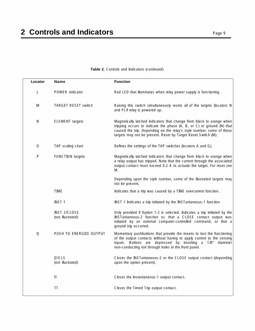
L POWER indicator Red LED that illuminates when relay power supply is functioning.
M TARGET RESET switch Raising this switch simultaneously resets all of the targets (locators Nand P) if relay is powered up.
N ELEMENT targets Magnetically latched indicators that change from black to orange whentripping occurs to indicate the phase (A, B, or C) or ground (N) thatcaused the trip. Depending on the relay’s style number, some of thesetargets may not be present. Reset by Target Reset Switch (M).
O TAP scaling chart Defines the settings of the TAP switches (locators A and G).
P FUNCTION targets Magnetically latched indicators that change from black to orange whena relay output has tripped. Note that the current through the associatedoutput contact must exceed 0.2 A to actuate the target. For reset seeM.
Depending upon the style number, some of the illustrated targets maynot be present.
TIME Indicates that a trip was caused by a TIME overcurrent function.
INST 1 INST 1 Indicates a trip initiated by the INSTantaneous-1 function.
INST 2/CLOSE(not illustrated)
Only provided if Option 1-2 is selected. Indicates a trip initiated by theINSTantaneous-2 function or, that a CLOSE contact output wasinitiated by an external computer-controlled command, or that aground trip occurred.
Q PUSH TO ENERGIZE OUTPUT Momentary pushbuttons that provide the means to test the functioningof the output contacts without having to apply current to the sensinginputs. Buttons are depressed by inserting a 1/8" diameternon-conducting rod through holes in the front panel.
I2/CLS(not illustrated)
Closes the INSTantaneous-2 or the CLOSE output contact (dependingupon the option present).
I1 Closes the Instantaneous-1 output contact.
TT Closes the Timed Trip output contact.
3 Operation by Front Panel Page 10
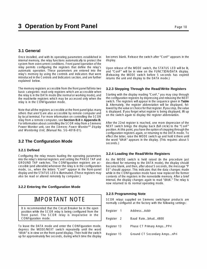
3.1 GeneralOnce installed, and with its operating parameters established ininternal memory, the relay functions automatically to protect thesystem from overcurrent conditions. Front panel operation of therelay permits configuring the registers that define the relay’sautomatic operation. These parameters are entered into therelay’s memory by using the controls and indicators that wereintroduced in the Controls and Indicators section, and are furtherexplained below.
The memory registers accessible from the front panel fall into twobasic categories: read-only registers which are accessible whenthe relay is in the DATA mode (the normal or working mode), andthe read/write registers which may be accessed only when therelay is in the CONFiguration mode.
Note that all the registers accessible at the front panel (plus manyothers that aren’t) are also accessible by remote computer andby local terminal. For more information on controlling the SCORrelay from a remote computer, see Section B.8 in Appendix B.For information about controlling the SCOR relay from a SiemensPower Monitor unit, see the Siemens Power MonitorTM Displayand Monitoring Unit, (Manual No. SG-4018-01).
3.2 The Configuration Mode
3.2.1 Defined
Configuring the relay means loading the operating parametersinto the relay’s internal registers and setting the PHASE TAP andGROUND TAP switches. The CONFiguration registers are ac-cessible (and alterable) whenever the relay is in the configurationmode, i.e., when the letters “ConF” appear in the front-paneldisplay and the STATUS LED is illuminated. (These registers mayalso be read or altered remotely by computer.)
3.2.2 Entering the Configuration Mode
IMPORTANT NOTEIt is recommended that the Circuit Breaker be in the openposition while the SCOR relay is being configured from thefront panel. The SCOR relay is inoperative in theCONFiguration mode.
To leave the DATA mode and enter the CONFiguration mode,depress the MODE/NEXT switch repeatedly until the word“dAtA” is in view on the front-panel display. Then hold the switchup for approximately five seconds, during which time the display
becomes blank. Release the switch after “ConF” appears in thedisplay.
Upon release of the MODE switch, the STATUS LED will be lit,and “ConF” will be in view on the FUNCTION/DATA display.(Releasing the MODE switch before 5 seconds has expiredreturns the unit and display to the DATA mode.)
3.2.3 Stepping Through the Read/Write Registers
Starting with the display reading “ConF,” you may step throughthe configuration registers by depressing and releasing the NEXTswitch. The registers will appear in the sequence given in Table3. Alternately, the register abbreviation will be displayed, fol-lowed by the value or choice for that register. If you stop, the valueis displayed. If you forget what register is being displayed, lift upon the switch again to display the register abbreviation.
After the 22nd register is reached, one more depression of theNEXT switch brings the display back (full circle) to the “ConF”position. At this point, you have the option of stepping through theconfiguration registers again, or returning to the DATA mode. Toeffect the latter, raise the MODE switch up and hold it there untilthe word “dAtA” appears in the display. (This requires about 5seconds.)
3.2.4 Loading the Read/Write Registers
As the MODE switch is held raised (in the procedure justdescribed for returning to the DATA mode), the display shouldbecome blank, and then, after about 5 seconds, the message “PEE” should appear. This indicates that the data changes madewhile in the CONFiguration mode have now replaced the formercontents of the registers in the nonvolatile memory. After a briefinterval, the display changes again to read “dAtA.” The relay isnow returned to its normal operating mode.
3.2.5 Programming Note
SCOR relays supplied on Siemens switchgear products arenormally configured at the factory with the following settings:
Register 1 Address...Addr
Register 2 Baud Rate...bAud...4800
Register 13 Phase CT Primary Amps...PPri
Register 15 Ground CT Secondary Amps...nPri

3 Operation by Front Panel Page 11
Table 3. Configuration Mode Display Sequence
RegisterDisplay
Sequence
RegisterDisplay
AbbreviationRegisterFunction
RegisterRange
1
2
3
4
5
6
7
8
9
10
Mode selection window
Indicates the present Address of the relay
Selected bAUd rate
Phase time dial setting
Ground time dial setting
Phase tAP calibrate
Ground tAP calibrate
Phase instantaneous #1
Phase instantaneous #2
Ground instantaneous #1
Ground instantaneous #2
11
12
13
14
15
16
17
18
19
20
Phase time overcurrent curve type
Ground time overcurrent curve type
Phase CT Primary Amps
Phase CT SEcondary Amps
Ground CT Primary Amps
Ground CT SEcondary Amps
Phase rAnge
Ground rAnge
demand Period
ground trip Enable?If 20 is YES, the following options are provided
20A Ground instantaneous trip (50 g)
20B Ground time trip (51 g)If the relay includes the auxiliary output relay,20C is provided
20C output relay to be tripped by the ground function
21
22
breaker Failure enable?
Wraps to the top(i.e., to the Mode selection window)
--
0001 to 0254
See text
0000 to 0099
0000 to 0099
0000 to 0099
0000 to 0099
00.75 to 020.0
00.75 to 020.0
00.75 to 020.0
00.75 to 020.0
b1 through c8
b1 through c8
5 through 5000
5 through 5000
5 always
5 always
HI or LO
HI or LO
1 to 30
YES or no
YES or no
YES or no
in2 or tin1
YES or no
--
*
* 20C permits option 1-2 to be configured as a dedicated ground trip output relay (see Page 3).If this is desired, select " in2 ", if not, select " tin1 ".

3 Operation by Front Panel Page 12
Dev i ceDev i ceT y p eT y p e
S e r i a lS e r i a lN u m b e rN u m b e r
CircuitCircuitN a m eN a m e
A d d r e s sA d d r e s s LocationLocationin Swgrin Swgr
N e wN e wAdd ress /Add ress /
D a t eD a t e
S C O R4700
3252092
Main #1Main #1
223323
Cell 1BCell 1B
S C O R4700
3332105
Feeder #1Feeder #1
224324
Cell 2ACell 2A
Use key assignment "A" to change an address
Table 4. List of Devices
Register 19 Demand Period Length...dPrdRegisters 14 and 16, the phase and ground secondaries, arealways 5.
Registers 17 and 18, the Tap Ranges, are pre-programmedbased on the style number ordered.
Registers 7, 8, 9 and 10, the Instantaneous #1 and #2 Functions,are options only supplied when ordered.
Thus, you normally only need to program registers 3 through 12in the field. These are the protective settings. The values areestablished by a time-current coordination study. You may alsoneed to make the choices for registers 19, 20 and 21. Valueswhich have been entered can be viewed by entering theCONFiguration mode, and scrolling through all items.
3.2.6 Programming the Address
Skip this item if the relay is not equipped with the communi-cations option.
Enter the configuration mode (described above) and advance tothe Addr register by depressing and releasing the NEXT switch.The SCOR unit address is displayed. This number which rangesfrom 1 to 254 is a unique address used for communicating tothis SCOR via its RS-485 port on the back of the case. Thenumber must be selected such that it is unique among alldevices connected on the same RS-485 loop (multiple devicesmay be daisy-chained together on a single communicationbus). When configuring the SCOR to communicate to a Si-emens Power Monitor unit, the address will be used to identifythe particular SCOR.
Relays initially are configured with the address 222. If this has notbeen changed, it must be done prior to accessing from thePower Monitor unit. It is suggested that a list of devices be madewith the information shown in Table 4.
3.2.7 Setting the Baud Rate
Using the procedures described above for entering theCONFiguration mode, display “bAUd” by advancing to thesecond register. (Reference Table 3.) The baud rate may nowbe adjusted by raising or depressing the UP/DOWN switch asrequired.
The baud rates available and their sequence are listed below.Note that the displayed value requires a multiplier of 1000 toarrive at the actual rate.
Baud Rate Displayed Value
19,200 19.20
9,600 9.600
4,800 4.800 (standard for Power Monitor)
2,400 2.400
1,200 1.200
600 0.600
300 0.300 (The next advance wrapsto 19.20.)
The selected baud rate is loaded into the relay’s nonvolatilememory with the return to DATA mode. The message “P EE” willappear briefly on the display to indicate that the new data isstored in nonvolatile memory
NOTE: The Power Monitor System uses a baud rate of 4800.
3 Operation by Front Panel Page 13
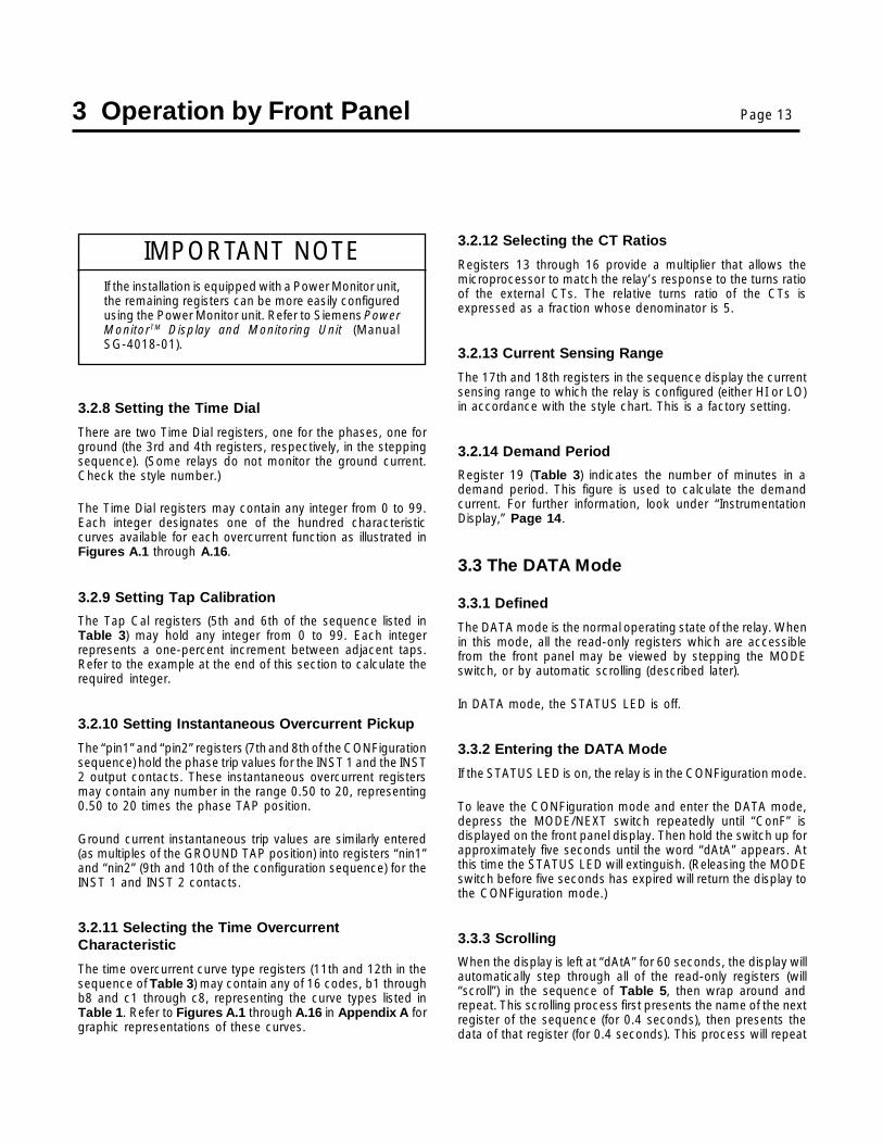
3.2.8 Setting the Time Dial
There are two Time Dial registers, one for the phases, one forground (the 3rd and 4th registers, respectively, in the steppingsequence). (Some relays do not monitor the ground current.Check the style number.)
The Time Dial registers may contain any integer from 0 to 99.Each integer designates one of the hundred characteristiccurves available for each overcurrent function as illustrated inFigures A.1 through A.16.
3.2.9 Setting Tap Calibration
The Tap Cal registers (5th and 6th of the sequence listed inTable 3) may hold any integer from 0 to 99. Each integerrepresents a one-percent increment between adjacent taps.Refer to the example at the end of this section to calculate therequired integer.
3.2.10 Setting Instantaneous Overcurrent Pickup
The “pin1” and “pin2” registers (7th and 8th of the CONFigurationsequence) hold the phase trip values for the INST 1 and the INST2 output contacts. These instantaneous overcurrent registersmay contain any number in the range 0.50 to 20, representing0.50 to 20 times the phase TAP position.
Ground current instantaneous trip values are similarly entered(as multiples of the GROUND TAP position) into registers “nin1”and “nin2” (9th and 10th of the configuration sequence) for theINST 1 and INST 2 contacts.
3.2.11 Selecting the Time OvercurrentCharacteristic
The time overcurrent curve type registers (11th and 12th in thesequence of Table 3) may contain any of 16 codes, b1 throughb8 and c1 through c8, representing the curve types listed inTable 1. Refer to Figures A.1 through A.16 in Appendix A forgraphic representations of these curves.
IMPORTANT NOTEIf the installation is equipped with a Power Monitor unit,the remaining registers can be more easily configuredusing the Power Monitor unit. Refer to Siemens PowerMonitorTM Display and Monitoring Unit (ManualSG-4018-01).
3.2.12 Selecting the CT Ratios
Registers 13 through 16 provide a multiplier that allows themicroprocessor to match the relay’s response to the turns ratioof the external CTs. The relative turns ratio of the CTs isexpressed as a fraction whose denominator is 5.
3.2.13 Current Sensing Range
The 17th and 18th registers in the sequence display the currentsensing range to which the relay is configured (either HI or LO)in accordance with the style chart. This is a factory setting.
3.2.14 Demand Period
Register 19 (Table 3) indicates the number of minutes in ademand period. This figure is used to calculate the demandcurrent. For further information, look under “InstrumentationDisplay,” Page 14.
3.3 The DATA Mode
3.3.1 Defined
The DATA mode is the normal operating state of the relay. Whenin this mode, all the read-only registers which are accessiblefrom the front panel may be viewed by stepping the MODEswitch, or by automatic scrolling (described later).
In DATA mode, the STATUS LED is off.
3.3.2 Entering the DATA Mode
If the STATUS LED is on, the relay is in the CONFiguration mode.
To leave the CONFiguration mode and enter the DATA mode,depress the MODE/NEXT switch repeatedly until “ConF” isdisplayed on the front panel display. Then hold the switch up forapproximately five seconds until the word “dAtA” appears. Atthis time the STATUS LED will extinguish. (Releasing the MODEswitch before five seconds has expired will return the display tothe CONFiguration mode.)
3.3.3 Scrolling
When the display is left at “dAtA” for 60 seconds, the display willautomatically step through all of the read-only registers (will“scroll”) in the sequence of Table 5, then wrap around andrepeat. This scrolling process first presents the name of the nextregister of the sequence (for 0.4 seconds), then presents thedata of that register (for 0.4 seconds). This process will repeat

3 Operation by Front Panel Page 14
endlessly while the relay remains in the DATA mode unlessdeliberately halted as described below.
To stop the display at a particular register, step the display to thedesired read-only register using the NEXT switch. (The registerswill appear in the sequence of Table 5). Raising the MODE/NEXT switch (above center) displays the name of the registerarrived at, and this register will be displayed until manuallyadvanced (except when “dAtA” is displayed).
Holding the MODE switch up for five seconds or more when theword “dAtA” is displayed puts the relay into the CONFigurationmode. Leaving the display at “dAtA” for 60 seconds will causeit to scroll again.
3.3.4 Instrumentation Display
The first seven registers of the Data Mode Display Sequence(Table 5) comprise the instrumentation display. The first fourregisters indicate the current at the CT primaries of each phasein kiloamperes. Registers 5,6, and 7 of the sequence indicatethe demand current (at the primaries in kiloamperes).
The Demand Registers show average kiloampere demand foreach monitored phase over a time period that is set into theDemand Period register. (The latter is not accessible from thefront-panel display.) The displayed average is recalculated each
Table 5. The Data Mo
1
2
3
4
5
6
7
8
9
minute for each phase by adding the Demand Period samplingswhich have accumulated for a given phase, then dividing thissum by the Demand Period number to obtain the averagedemand value. The latter is then displayed in the DemandCurrent register for the appropriate phase. (The demand currentvalues may also be read over the data link.)
All of the instrumentation registers (registers 1 through 7) displaytheir data in real time. Note that if the amperes are over or underthe operational scale of the ammeter, the display will show a rowof four dashes. The position of these dashes (high or low)indicate which way the parameter is out-of-range:
If current is below the 10% of TAP level, the row of dashes arealong the bottom of the display.
If current is above 150% of TAP, the row of dashes are along thetop of the display.
3.3.5 Error Code
The error code display is the last register of the sequencedescribed in Table 5. In the event of a malfunction, the ErrorCode register can narrow the search for possible causes. Whenthis register is at 0000, there is no error message. If not at 0000,advise the Siemens Customer Service representative of thereading. The relay will probably require repair at the factory.
de Display Sequence
--
0 to 50 kA
0 to 50 kA
0 to 50 kA
0 to 50 kA
0 to 50 kA
0 to 50 kA
0 to 50 kA
--
--

3 Operation by Front Panel Page 15
3.4 Setting the Relay (Example)
3.4.1 Example Defined
This hypothetical example has the following requirements:
Parameter For Phase For Ground
Time overcurrent 4.7A 1.6Apickup:
Pickup Range: High Low
Curve shape: Very Inverse Inverse
Time delay setting: 0.38 sec. @ 6 0.37 sec @ 6x pickup x pickup
Instantaneous 14.4A 6.4Aovercurrent pickup:
The following style number describes an appropriate relay forthis hypothetical application.
Model: SCOR Style: H1E Z5J B1NOS.
The second style digit indicates that HIGH range was chosen forphase monitoring, and LOW range for ground current monitor-ing.
3.4.2 Calculating the Settings
1. The time overcurrent characteristic must be selected suchthat it will coordinate with the other relays in the system tomeet the protective needs of the application. Assume thata Very Inverse function is suitable for phase protection, andInverse for ground protection. From Table 1 we see thatthese two characteristics are designated b6 and b5 re-spectively. The table also provides the figure numbers thatillustrate the desired curve sets.
2. Note that the phase time overcurrent pickup, 4.7 A, fallsbetween tap C and tap D of the HIGH range (as shown onthe front-panel chart illustrated in Figure 3). The phase TapCal value (which interpolates between TAP switch posi-tions) is then calculated as follows:
Given:
Pickup value = 4.7 ATap C (HIGH) = 4.0 ATap D (HIGH) = 5.0 A
Then: Set Phase Tap Switch (Front Panel) on CSpan = Tap D - Tap C =1.00Difference = Pickup value - Tap C =0.70Tap Cal value (phase) = Difference/Span x 100 =
0.70 /1.00 x 100 = 70
3. The ground time overcurrent pickup, 1.6 A, falls betweentap C and tap D of the LOW range (Figure 3). The groundTap Cal value is:
Pickup value = 1.6ATap C (LOW) = 1.5ATap D (LOW) = 2.0A
Then: Set Ground Tap Switch (Front Panel) on CSpan = Tap D - Tap C = 0.5Difference = Pickup value - Tap C = 0.1Tap Cal value (ground) = Difference/Span x 100 =
0.10/0.50 x 100 = 20
4. The ratio of the phase Instantaneous Overcurrent pickup tothe phase Time Overcurrent Tap is calculated as follows:
Phase Instantaneous Overcurrent = 14.4APhase Time Overcurrent Tap = 4.0Ratio = 14.4/4.0 = 3.6Set Pin1 to 3.6
5. The ratio of the ground Instantaneous Overcurrent pickupto the ground Time Overcurrent Tap is calculated asfollows:
Ground Instantaneous Overcurrent = 6.4AGround Time Overcurrent Tap = 1.5ARatio = 6.4/1.5 = 4.27Set nin1 to 4.27
6. From Curve b6 Figure A.6, find the phase TIME DIALsetting that corresponds to a delay of 0.38 seconds at 6times the pickup setting.
Answer: A TIME DIAL setting of 07.
7. From Curve b5 Figure A.5, find the ground TIME DIALsetting that corresponds to a delay of 0.37 seconds at 6times the pickup setting.
Answer: A TIME DIAL setting of 05.
3.4.3 Entering the Settings
1. Set PHASE TAP Switch (Front Panel) on C, and GROUNDTAP Switch (Front Panel) on C.

3 Operation by Front Panel Page 16
2. Load b6 into the phase Curve Type register, and b5 into theground Curve Type register.
3. Enter 70 into the phase Tap Cal register, and 20 into theground Tap Cal register.
4. Enter 3.6 into the phase instantaneous #1 overcurrentregister, and 4.27 into the ground Instantaneous #1 Over-current register.
5. Enter 07 into the phase TIME DIAL register, and 05 into theground TIME DIAL register.

4 Installation and Testing Page 17
4.1 GeneralWhen not shipped as part of switchgear, relay panel, circuitbreaker or control, the relay is shipped in a sturdy carton toprevent damage during transit. Immediately upon receipt of arelay, check the style number against the requisition and packinglist to see that they agree. Visually inspect the relay for damagethat may have occurred during shipment. If there is evidentdamage, immediately file a claim with the carrier and notify theSiemens Sales Office, or contact Electrical Apparatus Division,Customer Service. In the event the relay is not to be installedimmediately, store the relay in its original shipping carton in amoisture and dust free environment. When the relay is to beplaced in service, it is recommended that the verification tests(given later in this section) be performed prior to installation.
4.2 Relay Operating PrecautionsBefore installation or operation of the relay, note the followingprecautions.
1. A minimum of 0.2 A in the output circuit is required to ensureoperation of the FUNCTION targets.
2. Always reset targets by means of the target reset switch.
3. The relay is a solid state device and has been tested inaccordance with the requirements defined below underDIELECTRIC TEST. If a wiring insulation test is required onthe panel assembly where this relay is to be installed, it issuggested that the connecting plugs (or “paddles”) of therelay be removed and the cradle withdrawn from the caseso as not to produce false readings during the wiringinsulation test.
4. When the connecting plugs are removed, the relay isdisconnected from the operating circuit and will not providesystem protection. Always be sure that external operating(monitored) conditions are stable before removing a relay forinspection, test, or service. Be sure that connecting plugsare in place before replacing the front cover.
5. Be sure that the relay case is hard wired to earth groundusing no smaller than 12 AWG copper wire to the groundterminal on the rear of the unit. It is desirable to use aseparate ground wire to the ground bus for each relay. If thisis not practical, the number of relays sharing a ground wireshould be kept to a minimum.
4.3 Dielectric TestIn accordance with ANSI/IEEE C37.90-1989 and IEC 255-5,one-minute dielectric (high potential) tests may be performed upto 1500 VAC (45-65 Hz). This applies to all terminals, includingthe ports. Note that this device employs decoupling capacitorsto ground from terminals 3, 4, 9, A, and B. Accordingly, a leakagecurrent of 100 mA (max.) is to be expected at these terminals.
4.4 MountingThe SCOR relay is supplied in a standard S1 size drawout case.Figure 4 provides the outline dimensions for this case. The paneldrilling and cutout dimensions for this case are provided inFigure 5.
The relay does not have to be mounted vertically. Any convenientmounting angle may be chosen.
4.5 ConnectionsThe connections for the relay are shown in Figure 6 and Figure7. Incorrect wiring may result in damage to the relay. Be sure tocheck the model and style number of the relay with the StyleNumber Identification Chart (Figure 2) before connecting andenergizing the relay.
The terminals along the top and bottom of the back of the caseare suitable for use with wiring terminals and wire sizes of 14AWG or larger. The RS-485 port terminals A, B, and C (back ofcase, center) require a shielded, twisted pair.
Be sure the relay case is hard-wired to earth ground with nosmaller than 12 AWG copper wire. A ground terminal on the rearof the case is provided for this purpose. Ideally, each relay shouldhave a separate ground wire to the ground bus. If this is notpractical, the number of relays sharing a ground wire should bekept to a minimum.
The connections to the current transformers are shown inFigures 8 through 12. Diagrams are presented for single-phase,two-phase, and three-phase operation.

4 Installation and Testing Page 18
FRONT VIEW SIDE VIEW
Figure 4. Outline Dimensions
Figure 5. . . . . Panel Drilling and CutoutDimensions (For Semi-Flush Mounting)

4 Installation and Testing Page 19
19 17 15 13 11
20 18 16 14 12
OvercurrentSOLID-STATE PROTECTIVE RELAY
9 7 5 3 1
10 8 6 4 2
RS-485PORT
COM
MANUFACTURED FOR SIEMENSENERGY & AUTOMATION INC. BY
Basler ElectricHighland, Illinois
R
GND
(+) (-)
7 11
12
1
10
2
5
6
8
15
14
18
17
13
16
3
4
9
I
I
I
I
A
B
C
N
+
52b 1
1
BE1-51SCOR
COM (+) (-)
RS-485PORT
169
5
GND RX
DTR TX
RI2
2
RS-232 PORT
TARGET TARGET TARGET POWER
935
6 421
51 50-1
10 11
12
52TC
52a
52a
(-) TRIP BUS
(+) TRIP BUS
52b
1
2
LEGEND:
51 TIMED TRIP
50-1 INSTANTANEOUSOVERCURRENT #1
50-2 INSTANTANEOUSOVERCURRENT #2
1 RELAY DISABLED CONTACT
2 50-2 INSTANTANEOUSOVERCURRENT #2 REQUIRESOPTIONS 1-2 AND 2-C, PLUS APROGRAMMING CHANGE (SEEPAGE 3)
52a, 52b BREAKER AUXILIARYCONTACTS
52TC BREAKER TRIP COIL
50-2
SCOR RELAY
Figure 7. Control Circuits
Figure 6. Relay Connections

4 Installation and Testing Page 20
4.6 Verification Testing
4.6.1 General
The various test procedures which follow are intended to verifyoperation of the relay, and to set the various controls for aspecific application. Each phase of a two-or three-phase relaymay be tested as a single-phase device using the proceduresgiven. Check the Style Number Identification Chart (Figure 2)with the style number of the relay to identify the options includedwithin the specific relay to be tested.
All LED and target indicators should be checked in the courseof carrying out these test procedures. Reminder: The FUNC-TION targets require at least 0.2 A in the output circuit tooperate.
When test results do not fall within the specified tolerances, thefollowing should be evaluated.
1. The tolerances of the test equipment;
2. Cycle-to-cycle phase stability of the test equipment;
3. The tolerances of any external components used in the testsetup.
4.6.2 Scope
A complete checkout of the relay (or “verification” test) confirmsthat the following are within the published specifications.
1. Time overcurrent pickup;
2. Instantaneous pickup;
3. Time overcurrent timing;
4. Communications option. (The testing procedure for thisoption is covered in Siemens Power MonitorTM Display andMonitoring Unit (Manual SG-4018-01).
While every comprehensive test program should cover all of theabove items, the amount of testing within any category can varyover a great range. The operational test defined below illustratesan appropriate lower limit for this range.
4.7 Operational TestConfirmation of every parameter within the capability of thisrelay is usually not practical nor necessary except as an
acceptance procedure for a newly delivered relay. Succeedingtests can be reduced in scope to conserve time (and therebypermit more frequent tests). Such an operational test may beaccomplished by scaling down the verification tests of thissubsection as follows:
1. By concentrating on the parameters actually required in theassigned application;
2. By using spot tests that check (for example) only one or twomultiples of applied TAP current at only one or two TAPpositions.
Accordingly, the procedures described below can serve as thebasis for both verification and operational testing.
This procedure verifies the operation of the unit. Check the StyleNumber Identification Chart (Figure 2) with the style number ofthe relay to identify the options included within the specific relayto be tested.
4.7.1 Equipment Required
1. The current source used in the following tests should havethe following capabilities.
a. Current output should be switchable so that the testcurrent can be set before it is applied to the relay. Theselected operating current can then be switched to therelay’s sensing inputs.
b. The current source needs to be capable of deliveringat least 20 A. This is necessary to test the full capabilityof the instantaneous overcurrent element.
c Because the current levels used to verify operation ofthe instantaneous overcurrent element(s) may exceedthe continuous current rating of the relay, it is sug-gested that the current source include a provision forautomatic removal of the test current following a trip.
2. A timer accurate to within 0.001 seconds.
3. Two test plugs, Siemens p/n 00-871-854-001, Basler p/n10095, or GE p/n XLA12A. (Replaces the “paddles” whentesting an installed relay.)
4. For bench testing: An appropriate AC or DC power sourcefor relay operation.

4 Installation and Testing Page 21
Figure 8. Single-Phase Current Sensing Connections
NOTE
Several proprietary test sets are marketed whichcombine the current source and timer, and includeother features to simplify setup.
4.7.2 Preliminary Steps
1. With the connecting plugs removed, connect the unit asshown in the following figure numbers:
1st Digit of FigureStyle Number Sensing Input Configuration Number
K Single-phase 8
G Three-phase 9
H Three-phase-with-ground 10, 11
X Two-phase-with-ground 12
2. Insert the relay connecting plugs if bench testing. If relay isinstalled, insert test plugs instead. Before applying power,check that the Relay Fail contact is closed (terminals 11 and12).
3. Apply operating power at terminals 3 and 4. Verify that thePOWER LED is lit, and that the relay disabled contact isopen.
4. Load 00 into the Phase Tap Cal register.
5. Load 99 into the Time Dial register.
4.7.3 Time Overcurrent Pickup Test
The phase current pickup of the relay will be set at the factoryto operate on one of the two available ranges: HIGH or LOW. Ifground current is monitored, it will also be set for one of the tworanges. Determine which range applies by noting the indicationof the tap range on the front panel. (One for phase and one forground.)
Figure 9. Three-Phase Current Sensing Connections

4 Installation and Testing Page 22
Figure 10. Three-Phase with Residually ConnectedGround, Current Sensing Connections
4.7.3 Time Overcurrent Pickup Test (Continued)
Verify time overcurrent pickup as follows:
1. After performing the above preliminary steps, connect theinput current source to terminals 7 and 8 on the relay case(Phase A).
2. Set the PHASE TAP switch to position A.
3. Adjust the input current source to 110% of the value shownon the front panel table for TAP A (HIGH or LOW range asindicated by the second digit of the style number). Observethat the PHASE A TMG LED illuminates.
4. Adjust the current source so that the PHASE A TMG LEDgoes dark. The current applied when the LED extinguishesshould be between the pickup point (from the table) and .90times the pickup point.
5. Repeat steps 3 and 4 with the PHASE TAP switch set to B,C, D, E, F, G, H, I, and J successively.
NOTEIf this is a single-phase relay, this completes the TimeOvercurrent Pickup Test. If this is a three-phase relay,perform steps 6, 7, 8, and 9 below. If two-phase-with-ground relay, perform steps 6, 7, 10, and 11 below. Ifthree-phase-with-ground, perform all of the followingsteps.
6. Disconnect the input current source from terminals 7 and8 (Phase A) and connect it to terminals 14 and 15 (PhaseB).
7. Repeat steps 2 through 5 above for Phase B.
8. Disconnect the input current source from terminals 14 and15 (Phase B) and connect it to terminals 17 and 18 (PhaseC).
9. Repeat steps 2 through 5 above for Phase C.
10. Disconnect the input current source from terminals 17 and18 (Phase C) and connect it to terminals 13 and 16(Ground).
11. Repeat steps 2 through 5 above for ground current.
Figure 11. Three-Phase with Independent Ground,Current Sensing Connections

4 Installation and Testing Page 23
A
B
C
A B C
52
LINE
A
C
N
518
5117
5113
517
5118
5116
LEGEND
51 OVERCURRENT RELAY52 POWER CIRCUIT BREAKER
BUS
Figure 12. Two-Phase with Residually ConnectedGround, Current Sensing Connections
4.7.4 Timing Test
The timing characteristics available by programming the relayare illustrated in Figures A.1 through A.16. Output trip shouldoccur as shown for any given TIME DIAL setting, to within 10%or 20 milliseconds (whichever is greater). Verification of timingaccuracy can be limited to low current levels for convenience.
Verify timing accuracy as follows:
1. After performing the “Preliminary Steps’’ (Page 19), con-nect the input current source to terminals 7 and 8 on therelay case (Phase A).
2. Select the time overcurrent characteristic of choice byentering its identifying code number into the Phase curve(Pcur) register. (Reference Table 3.) Similarly load theGround curve register with the characteristic of choice (ifground current monitoring is a relay option).
3. Set the PHASE TAP switch to position A. Load 99 into theTime Dial register. (The Phase tAP calibrate register is stillat the 00 setting given in “Preliminary Steps.’’)
4. Measure the timing from the application of input current tooutput contact closure for currents that are adjusted to thefollowing multiples of TAP:
a. 2.0 x TAP, and
b. 5.0 x TAP
Check the results against the graphed values.
5. Adjust the TIME DIAL to 20 and repeat step 4.
NOTEIf this is a single-phase relay, this concludes a minimalTiming Test. Other TAP switch positions may be triedwithin the limitations of the current source. If this is athree-phase relay with ground, perform the followingsteps.
6. Disconnect the input current source from terminals 7 and8 (Phase A) and connect it to terminals 14 and 15 (PhaseB).
7. Repeat steps 2 through 5 above for Phase B.
8. Disconnect the input current source from terminals 14 and15 (Phase B) and connect it to terminals 17 and 18 (PhaseC).
9. Repeat steps 2 through 5 above for Phase C.
10. Disconnect the input current source from terminals 17 and18 (Phase C) and connect it to terminals 13 and 16(Ground).
11. Repeat steps 2 through 5 above for ground current.

4 Installation and Testing Page 24
4.7.5 Instantaneous Overcurrent Pickup Test
The phase current pickup of the relay will be set at the factoryto operate on one of the two available ranges: HIGH or LOW. Ifground current is monitored, it will also be set for one of the tworanges. Determine which range your relay is set for by theindication of the tap range on the front panel. (One for phase andone for ground.)
NOTEWhen testing the instantaneous element, the thermalrating of the relay must not be exceeded. The maxi-mum continuous current rating for each input is fivetimes tap or 20 A, whichever is less. The one-secondcurrent rating for each input is 50 times tap or 500 A,whichever is less. For ratings at less than one second,refer to formula on Page 41.
Verify instantaneous overcurrent pickup as follows:
1. After performing the “Preliminary Steps” (Page 19), con-nect the input current source to terminals 7 and 8 on therelay case (Phase A).
2. Load .50 into the Phase Instantaneous #1 register. (Ap-pears as Pin1 in the display, and in Table 3, on Page 11.)
3. Set the PHASE TAP switch to position A.
4. Starting from 0 A, slowly increase the input current sourceuntil the INST 1 output contact closes. This should occur at0.5 the value shown on the front panel table for TAP A.
5. Adjust the current source so that the INST 1 relay opens.The current applied should be above 71.25% of the TAPvalue (reference the front panel table).
6. Repeat steps 3 through 5 above with the PHASE TAPswitch set to B, C, D, E, F, G, H, I, and J successively.
7. If Option 1-2 is present and is used as Inst 2, follow theprocedures of steps 2 through 6 for testing the Instanta-neous 2 pickup and output.
NOTEIf this is a single-phase relay, this completes theInstantaneous Overcurrent Pickup Test. If this is athree-phase relay, perform steps 8 through 12 below.If a two-phase-with-ground relay, perform steps 8, 9,12, and 13. If three-phase-with-ground, perform all ofthe following steps.
8. Disconnect the input current source from terminals 7 and8 (Phase A) and connect it to terminals 14 and 15 (PhaseB).
9. Repeat steps 2 through 7 above for Phase B.
10. Disconnect the input current source from terminals 14 and15 (Phase B) and connect it to terminals 17 and 18 (PhaseC).
11. Repeat steps 2 through 7 above for phase C.
12. Disconnect the input current source from terminals 17 and18 (Phase C) and connect it to terminals 13 and 16(Ground).
13. Repeat steps 2 through 7 above for ground.
4.7.6 Testing of Option 1-2 Command CloseFunction
This function can only be used and tested if the Communica-tions Option is present, and a Power Monitor unit or PowerMonitor PC unit is present.
1. Close the 52b contact input on the relay (terminals 3 and9) which simulates the open breaker.
2. Select the “Command Close” command in the PowerMonitor. For detailed instructions refer to the SiemensPower MonitorTM Display and Monitoring Unit (Manual SG-4018-01).
3. You should observe the closure of the programmableoutput contact (terminals 5 and 6).
4. Open the 52b contact input. You should observe theprogrammable output contact open.
5. Repeat step 2. Terminals 5 and 6 should not close.
5 Maintenance Page 25
5.1 GeneralStatic devices require no preventive maintenance other than aperiodic operational test (see Page 20). If the relay fails tofunction properly, contact Siemens Customer Service. Whenreturning the relay to the factory, ship the entire relay cradleassembly, preferably in its case.
5.2 StorageThis protective relay contains aluminum electrolytic capacitorswhich generally have a storage life expectancy in excess of tenyears at storage temperatures less than 40°C. Typically, the lifeexpectancy of the capacitor is cut in half for every 10°C rise intemperature. Storage life can be extended if, at one-yearintervals, power is applied to the relay for a period of 30 minutes.
5.3 TimekeepingThe real-time clock within the relay, once set by the PowerMonitor unit after power up, maintains time to a resolution of 0.01second; however, drift within the clock can be as much as 0.5seconds per day. In order to keep all of the clocks in the systemin proper synchronization, the Power Monitor periodically broad-casts the correct time.
Note that changing the time within a relay by seconds or minutescan upset instrumentation functions such as demand calcula-tions.

6 References Page 26
1. EIA Standard: EIA 485. (Also known as the RS-485 Stan-dard.) Published by Electronic Industries Association (April1983).
2. Siemens Power MonitorTM Display and Monitoring Unit(Manual No. SG-4018-01).
3. Siemens SCOR Protocol.
4. Siemens Isolated Multi-DropTM RS-232 to RS-485 Con-verter (Manual No. SG-6048).
5. Siemens Power Monitor PCTM User's Guide (Manual No.SG-4028).
6. Siemens SIEServe™ Electrical Distribution CommunicationSoftware User's Manual (Manual No. SG-6058).
7. Siemens WinPM™ Power Monitoring and Control for Win-dows User's Manual (Manual No. SG-6118).
8. Siemens PC32F Power Monitor Data Sheet (Bulletin No.SG-3211).

Appendix A Time Overcurrent Characteristic Curves Page 27
Figure A.1 through Figure A.16 illustrate the characteristiccurves that are programmed into the nonvolatile memory of thisrelay.
Refer to Table 1 on Page 5 for a listing of the 16 characteristiccurves.
Note that a drawing number is given under each caption. Use thisnumber to order a full-size (10" x 12") Characteristic Curve set.
The Phase and Ground Instantaneous Time Curves are pre-sented in Figures A.17 and A.18 respectively.

Appendix A Time Overcurrent Characteristic Curves Page 28
Figure A.1 Timing Type b1: Short Inverse Time(Dwg. No. 18-752-294-001)
Figure A.2 Timing Type b2: Long Inverse Time(Dwg. No. 18-752-294-002)

Appendix A Time Overcurrent Characteristic Curves Page 29
Figure A.3 Timing Type b3: Definite Time(Dwg. No. 18-752-294-003)
Figure A.4 Timing Type b4: Moderately Inverse(Dwg. No. 18-752-294-004)

Appendix A Time Overcurrent Characteristic Curves Page 30
Figure A.5 Timing Type b5: Inverse Time(Dwg. No. 18-752-294-005)
Figure A.6 Timing Type b6: Very Inverse Time(Dwg. No. 18-752-294-006)

Appendix A Time Overcurrent Characteristic Curves Page 31
Figure A.7 Timing Type b7: Extremely Inverse(Dwg. No. 18-752-294-007)
Figure A.8 Timing Type b8: I2T(Dwg. No. 18-752-294-008)

Appendix A Time Overcurrent Characteristic Curves Page 32
Figure A.9 Timing Type c1: I2T w/Limit 1(Dwg. No. 18-752-294-009)
Figure A.10 Timing Type c2: I2T w/Limit 2(Dwg. No. 18-752-294-010)

Appendix A Time Overcurrent Characteristic Curves Page 33
Figure A.11 Timing Type c3: I2T w/Limit 3(Dwg. No. 18-752-294-011)
Figure A.12 Timing Type c4: I2T w/Limit 4(Dwg. No. 18-752-294-012)

Appendix A Time Overcurrent Characteristic Curves Page 34
Figure A.13 Timing Type c5: I2T w/Limit 5(Dwg. No. 18-752-294-013)
Figure A.14 Timing Type c6: I2T w/Limit 6(Dwg. No. 18-752-294-014)

Appendix A Time Overcurrent Characteristic Curves Page 35
Figure A.15 Timing Type c7: I2T w/Limit 7(Dwg. No. 18-752-294-015)
Figure A.16 Timing Type c8: I2T w/Limit 8(Dwg. No. 18-752-294-016)
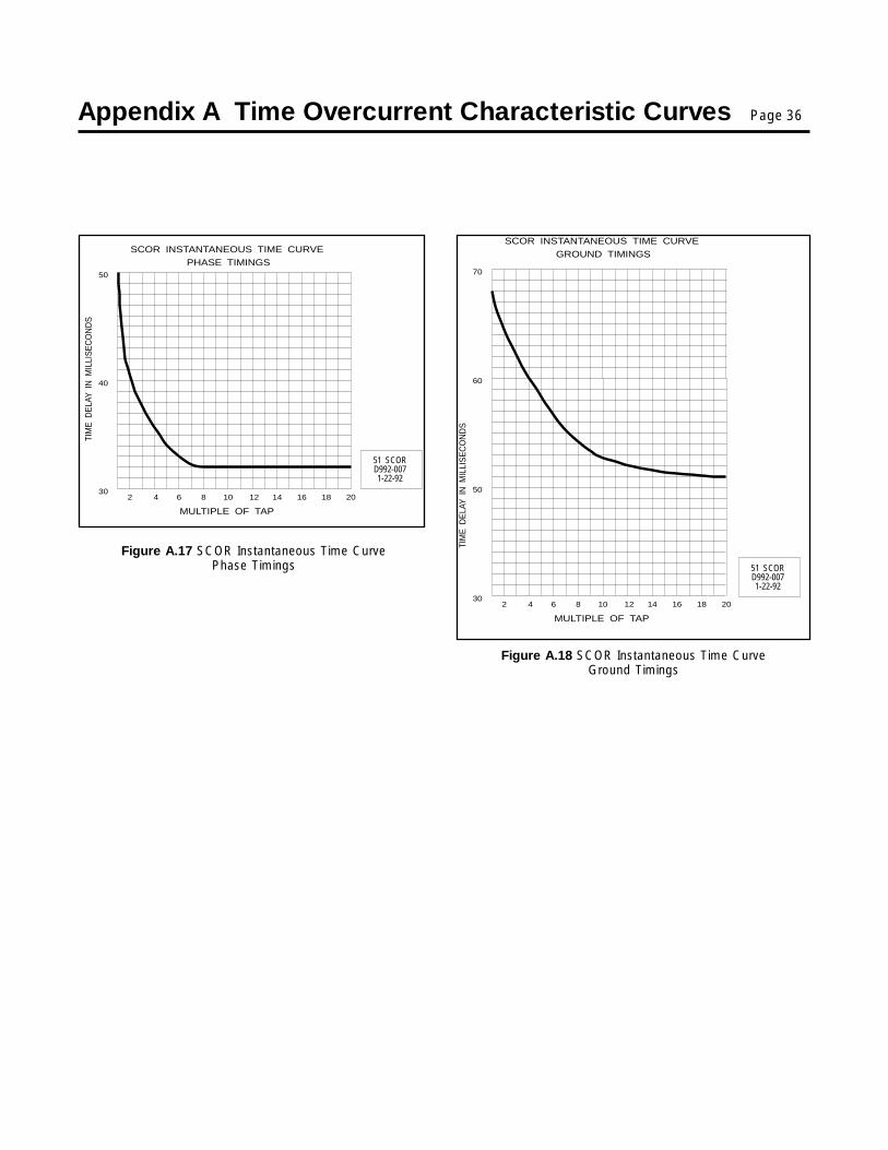
Appendix A Time Overcurrent Characteristic Curves Page 36
30
50
60
70
2 4 6 8 10 12 14 16 18 20
TIM
ED
ELA
YIN
MIL
LIS
EC
ON
DS
GROUND TIMINGSSCOR INSTANTANEOUS TIME CURVE
MULTIPLE OF TAP
51 SCORD992-0071-22-92
Figure A.17 SCOR Instantaneous Time CurvePhase Timings
Figure A.18 SCOR Instantaneous Time CurveGround Timings
30
40
50
2 4 6 8 10 12 14 16 18 20
TIM
ED
ELA
YIN
MIL
LIS
EC
ON
DS
PHASE TIMINGSSCOR INSTANTANEOUS TIME CURVE
MULTIPLE OF TAP
51 SCORD992-0071-22-92

Appendix B Functional Description of Operation Page 37
B.1 GeneralThe SCOR relay is a microprocessor-based overcurrent relaythat can optionally be equipped to communicate with a remotecomputer. The following text is referenced to Figure B.1, whichis a functional block diagram that illustrates the overall operationof a fully implemented version of the relay.
B.2 Current SensingThe SCOR relay can be provided for single-phase, two-phase-with-ground, three-phase, or three-phase-with-ground currentmonitoring. The illustrated relay is of the three-phase-with-ground style.
The internal current sensing transformers are designed to receivetheir input from the 5 A nominal secondaries of standard currenttransformers (CTs). Note the dual primaries of the internaltransformers. One or the other is connected by the factory toobtain a LOW or a HIGH current sensing range (0.50 to 5.0 A, or2.00 to 11.00 A) in accordance with the specified Style Numberof the relay.
The outputs of the internal transformers are applied to scalingcircuits (one for each of the phases, one for ground) that converteach of the input currents to a voltage level that can be utilizedwithin the relay.
A “coarse” incremental adjustment for the current pickup settingis provided by the TAP switches. These are front-panel rotaryswitches; one for the phases, and another for ground, if groundcurrent is monitored. The current setting represented by each ofthe 10 switch positions is given for each range (HIGH and LOW)in the table printed on the front panel. (Reference Figure 3.)
The “fine” adjustment of the current pickup point is determinedby the value (0 to 99) stored in the relay’s Tap Cal registers (again,one setting for the phases, one for ground). When the Tap Calregister contains the value 0, the pickup setting of the relay is theindicated TAP setting.
The Tap Cal registers provide a means of adjusting the timed trippickup between the selected position of the TAP switch and thenext higher position. For example, when the TAP switch is set toposition A, the Tap Cal register provides an adjustment from 0.50to 1.00 A for the LOW range, and from 2.00 to 3.00 A for the HIGHrange. EXCEPTION: At the highest TAP position (i.e., J), thesetting of the Tap Cal register is ignored. Therefore the J valuesof 5.0 and 11.00 represent the upper limits of the LOW and HIGHranges, respectively.
B.3 Power Supply
B.3.1 General
The solid state power supply is a low burden, flyback switchingdesign which delivers a nominal +5 and +/-12 VDC to the relay’sinternal circuits; also an isolated +5 Vdc for the communicationscircuits.
The input terminals of the power supply are not polarity sensitive.A red POWER LED illuminates to indicate that the power supplyis functioning.
B.3.2 Loss-of-Power Sensing
A loss-of-power circuit monitors the power supply. If power isinterrupted, a Power Fail signal is delivered to the computer intime for it to store all vital information in non-volatile registers. Alsoat this time, the Relay Disabled output contact closes asexplained below under “Outputs.”
B.4 MultiplexerA multiplexer is utilized to select each current sensing input.These inputs are then supplied to the sample-and-hold circuit,and then to the level shifter. The level of each input sample isstrobed into the microprocessor, where analog-to-digital con-version is implemented.
B.5 Internal MicrocomputerThe onboard computer fulfills many of the logic and signalprocessing functions described in the following paragraphs, andperforms the time delay computations.
B.5.1 Analog-to-Digital Converter
The voltage representing a component of the actual sensedcurrent is presented to the analog-to-digital (A/D) converter. TheA/D converter supplies the equivalent binary value of the sensedcurrent. The accumulator stores a number of these squaredsamples and presents this sum to the trip computer. Themicrocomputer then calculates the true RMS value of the currentat each input.
B.5.2 RMS Sensing
The SCOR protective relay uses RMS Sensing, a technology firstintroduced by Siemens in 1985, to sample the current waveshape and quickly calculate the effective heating value of thecurrent. SCOR relays evaluate the impact of harmonics andprovide accurate circuit protection. The SCOR relay uses a sum

Appendix B Functional Description of Operation Page 38
of squares algorithm for both determining trip level and forcalculating metered values of the relay current level. The inputwaveform is sampled several times to determine instantaneousvalues. These instantaneous values are processed to obtain thetrue RMS value of the input current.
B.5.3 Time Overcurrent Calculations
If the magnitude of the current exceeds the pickup setting, themicroprocessor calculates the required time delay by evaluat-ing the magnitude of the overcurrent in the context of the desiredtime overcurrent response curve. (All of the time overcurrentfunctions that are graphically illustrated in Figures A.1 throughA.16 are in the computer’s memory.)
Figure B.1 Function
The current inputs are continuously polled and the calculationsupdated once for every 60 Hz (line) cycle. As long as the sensedcurrent is above the pickup point, the elapsed time is accumu-lated toward trip. However, once the sensed current falls belowpickup, the relay is reset and all accumulated time is cancelled.
When the value of a sensed current exceeds the pickup setting,the TIMING LED for that phase will light. The LED will stay lit aslong as the sensed current exceeds the selected pickup level.
B.5.4 High/Low Range Register
It was noted earlier in this section that the input transformersmust be wired for one of two sensing ranges: HIGH or LOW. Thisinformation is recorded (at the factory) into the HI/LO Range
al Block Diagram
Appendix B Functional Description of Operation Page 39
Registers; one register for the phases, one for ground. Allcurrent sensing and pickup data is weighted by the computeraccordingly.
B.5.5 Watchdog Circuitry
The watchdog circuit checks that the microcomputer is opera-tional. If some transient condition has disrupted its normalpattern of operation, the watchdog will momentarily close therelay disabled output contact, reset the computer, and reinitializethe program. The computer is then restarted, and the relayresumes its monitoring function (without human input).
B.6 Outputs
B.6.1 General
Although the output relays are controlled by the microcomputer,the output interface contains the transistors that energize them.With the exception of the Relay Disabled contact (describedbelow), all of the output contacts are of the normally open typeand have targets associated with them.
B.6.2 Relay Disabled Output
The Relay Disabled output contact is of the normally closed (NC)type. It is held open (by the output relay’s energized coil) at alltimes after power-up unless a malfunction is detected as notedbelow. (This arrangement provides for a fail-safe output signal,since the contact is able to close an external alarm circuit evenin the absence of power.)
The Relay Disabled output contact will close if:
1. The power supply voltage falls below requirements; or
2. The upper connecting plug (“paddle”) is removed.
Additionally, the Relay Disabled output contact will momentarilyclose if the watchdog circuit detects abnormal operation of thecomputer. (Actually, detection of abnormal operation leads tomicrocomputer reset in an effort to correct the problem, and thereset operation causes the contact closure.)
B.6.3 Instantaneous and Command Close Options
One or two instantaneous outputs are available as options. Thetrip points for these options are selected by a programmingmethod described in Section 3, , , , , Operation by Front Panel.
When two instantaneous outputs are selected, one of them canbe programmed to operate directly from the system computer
(assuming that the Communications Option is also present). Theprogramming information is supplied in the Siemens PowerMonitorTM Display and Monitoring Unit (Manual SG-4018-01).(The second output relay, when controlled by the computer,cannot simultaneously serve as an instantaneous output.)
Optionally, this extra output relay can be programmed as adedicated ground trip contact.
B.7 Target IndicatorsTargets are provided for each function (TIME, INST 1, and INST2/CLOSE or GROUND), and for each phase and ground that ismonitored on multiphase relays. Each target indicator is visibleon the front panel of the relay with the cover in place. Whenoperated, the disk in the target changes from black to orange,and is magnetically latched in this position.
The FUNCTION targets only operate when a minimum of 0.2 Aflows through the associated relay’s output circuit. This is toprovide confirmation that the contact actually did close and thata signal was delivered. The ELEMENT targets, i.e., phase andground are internally operated.
To monitor output current, the coil of a special reed relay isplaced in series with the output contacts. The reed relay signalsthe target. (The series impedance of the reed relay coil is lessthan 0.1 ohm.)
To reset the target(s) after an abnormal system condition hasbeen cleared, manually raise the target reset switch on the frontof the relay, or its extension bar that protrudes through thebottom of the cover. (The relay must be under power to reset atarget.)
NOTEResetting the targets in this manner will not reset thealarm messages provided on the communication link.
B.8 Communications OptionThe SCOR relay includes provision for the future addition of theoptional communication board as standard. If the communica-tions option 2-C is selected initially, the relay is provided with anRS-232 port on the front panel, and an RS-485 port on the backof the case.
Appendix B Functional Description of Operation Page 40
B.8.1 Local RS-232 Port
A 9-pin RS-232 communication port is provided on the front ofthe relay for local data readout and programming when thecommunication option is installed.
Use of this port is restricted to Siemens field service and factorypersonnel, and connection to this port automatically disablesremote RS-485 communications.
B.8.2 Local or Remote with SiemensPower Monitor Unit
The RS-485 port permits interconnecting multiple SCOR relays,4700 power meters, Static Trip IIIC trip units, and other compat-ible devices via an industry standard shielded twisted-pair EIARS-485 communication bus to a Siemens Power Monitordisplay and monitoring unit. A Power Monitor unit can accom-modate up to 64 devices. The bus length can be up to 4000 feet.The Power Monitor unit is intended to be a “factory floor” tool,and can be mounted on medium-voltage or low-voltage switch-gear, serving all circuit breakers within a substation or controlroom, or it may be located remotely at a central maintenance/control area.
The Power Monitor unit works intimately with SCOR relays toprovide comprehensive displays, monitoring, and logging of allthe data from all devices on the bus. It is a dedicated computerwhich constantly monitors each device on the communicationsbus. Every data item available from the front of the relay is alsoavailable at the Power Monitor unit. The Power Monitor unit alsoprovides information not available on the SCOR display, such as
system diagrams with real-time amperes and circuit breakerposition; detailed data for all phases and ground simultaneouslywhich changes to a trip log with time stamped currents at thetime of trip, relay target operation plus watchdog status; a MIN/MAX log; and an event log with a time stamped chronologicallisting of events of all devices on the bus. The event log is apowerful tool for operating and maintenance personnel.
Configuration of the SCOR relay is read and stored by the PowerMonitor unit, and the relay can be configured or changedremotely from the Power Monitor unit (except for the tapswitches which must be set manually on the front panel).Configuration and changes from the Power Monitor unit ispassword protected.
For complete operation of the SCOR relay with a Power Monitorunit, see the Siemens Power MonitorTM Display and MonitoringUnit (Manual No. SG-4018-01).
B.8.3 Local or Remote by Owner’s Computer
Installations which do not have a Power Monitor unit can use acomputer equipped with Siemens Power Monitor-PC programconnected through a Siemens Isolated Multidrop RS-485/RS-232 converter. If the SCOR relays and other devices areinterconnected by the communication bus described above,the computer can access all devices, and display the same dataas described for the Power Monitor unit. This can be helpfulwhen initially configuring a system which has multiple devices,and for periodic downloading of event and MIN/MAX data. Forinformation about operation with the Power Monitor PC, refer tothe Siemens Power Monitor PCTM User's Guide (Manual No.SG-4028).

Appendix C Specifications Page 41
The SCOR relay is available in single-phase, three-phase, two-phase-with-ground, and three-phase-with-ground configura-tions, and with the features and capabilities described in TableC.1.
Table C.1 Specifications
IKT
==
=(500 A or 50 times TAP) 2
Time that current flows (in seconds)
K/T where√
Current Sensing Inputs The unit is designed to operate from the secondary of a standard current transformerrated at 5 A. The maximum continuous current rating for each input is five times tapor 20 A, whichever is less.
The one-second current rating for each input is 50 times tap or 500 A, whichever isless. Ratings at less than one second are calculated as:
Current Sensing Burden Less than 0.025 ohms per phase at nominal 60 Hz. (see Table 3)
Frequency (nominal) 60 Hz.
Time Overcurrent
Pickup Ranges: Two ranges are available: HIGH (2.0 - 11.0 A), and LOW (0.5 - 5.0 A). Range isindependently specified for phase and ground by the second digit of the StyleNumber. The TAP range windows on the front panel indicate which range (HIGH orLOW) is specified. Selection of the desired tap is made using the rotary selectorswitch(s) on the front panel. Refer to the table on the front panel for the various tapratings in secondary amps.
Pickup Adjustment: Incrementally adjustable over the selected range by a front-panel (TAP) selectorswitch ("coarse"), and by numerical data entered into the Tap Cal register ("fine").
Pickup Setting Accuracy: The accuracy of the pickup setting is +/- 2% of the programmed setting over the fullspecified range of the relay at 60 Hz.
Pickup Repeatability: Within 2%.
Dropout Ratio: Better than 80% of the established pickup level within 50 milliseconds.
Instantaneous Overcurrent
Pickup Range: 0.5 to 20 times the value of the time overcurrent tap setting.
Pickup Setting Accuracy: The accuracy of the instantaneous pickup setting is +/- 2% of the programmedsetting over the full specified range of the relay at 60 Hz.
Dropout Ratio: Better than 80% of the established pickup level within 50 milliseconds.
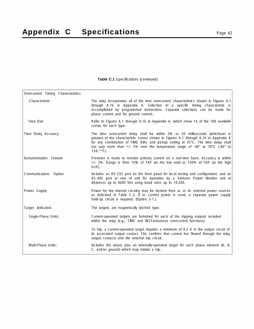
Appendix C Specifications Page 42
Table C.1 Specifications (continued)
Overcurrent Timing Characteristics
Characteristic: The relay incorporates all of the time overcurrent characteristics shown in Figures A.1through A.16 in Appendix A. Selection of a specific timing characteristic isaccomplished by programmed instructions. Separate selections can be made forphase current and for ground current.
Time Dial: Refer to Figures A.1 through A.16 in Appendix A, which show 14 of the 100 availablecurves for each type.
Time Delay Accuracy The time overcurrent delay shall be within 5% or 20 milliseconds (whichever isgreater) of the characteristic curves shown in Figures A.1 through A.16 in Appendix Afor any combination of TIME DIAL and pickup setting at 25°C. The time delay shallnot vary more than +/- 5% over the temperature range of -40° to 70°C (-40° to158.°°F).
Instrumentation Feature Provision is made to monitor primary current on a real-time basis. Accuracy is within+/- 2%. Range is from 10% of TAP (at the low end) to 150% of TAP (at the highend).
Communications Option Includes an RS-232 port on the front panel for local testing and configuration, and anRS-485 port at rear of unit for operation by a Siemens Power Monitor unit atdistances up to 4000 feet using baud rates up to 19,200.
Power Supply Power for the internal circuitry may be derived from ac or dc external power sourcesas indicated in Table C.2. If ac control power is used, a separate power supplyhold-up circuit is required. (Option 3-1.)
Target Indicators The targets are magnetically latched type.
Single-Phase Units: Current-operated targets are furnished for each of the tripping outputs includedwithin the relay (e.g., TIME and INSTantaneous overcurrent functions).
To trip, a current-operated target requires a minimum of 0.2 A in the output circuit ofits associated output contact. This confirms that current has flowed through the relayoutput contacts and the external trip circuit.
Multi-Phase Units: Includes the above plus an internally-operated target for each phase element (A, B,C, and/or ground) which may initiate a trip.

Appendix C Specifications Page 43
Table C.1 Specifications (continued)
Outputs Output contacts are rated as follows:
Resistive: 120/240 VAC - Make 30 A for 0.2 seconds, carry 7 A continuously, break 7 A.
250 VDC - Make and carry 30 A for 0.2 seconds, carry 7 A continuously, break 0.3 A.
500 VDC - Make and carry 15A for 0.2 seconds, carry 7 A continuously, break 0.1 A.
Inductive: 120/240 VAC, 125/250 VDC - Break 0.3 A (L/R = 0.04).
Shock In standard tests the relay has withstood 15 g in each of three mutually perpendicularaxes, without structural damage or degradation of performance.
Vibration In standard tests the relay has withstood 2 g in each of three mutually perpendicularaxes, swept over the range of 10 to 500 Hz for a total of six sweeps, 15 minutes eachsweep, without structural damage or degradation of performance.
Isolation 1500 VAC at 60 Hz for one minute, in accordance with IEC 255-5 and ANSI/IEEEC37.90-1989 (Dielectric Test).
Surge Withstand Capability Qualified to ANSI/IEEE C37.90.1-1989 Standard Surge Withstand Capability Test andFast Transient Test, and IEC 255-5 Impulse Test and Dielectric Test.
Radio Frequency Interference(RFI)
Maintains proper operation when tested in accordance with ANSI/IEEEC37.90.2-1987.
Temperature (Operating) -40° to 70°C (-40° to 158°F).
Temperature (Storage) -65° to 100°C (-85° to 212°F).
Weight 14.8 pounds net.
Case Size S1. (Dimensions are given in Figure 4.)
Certification UL
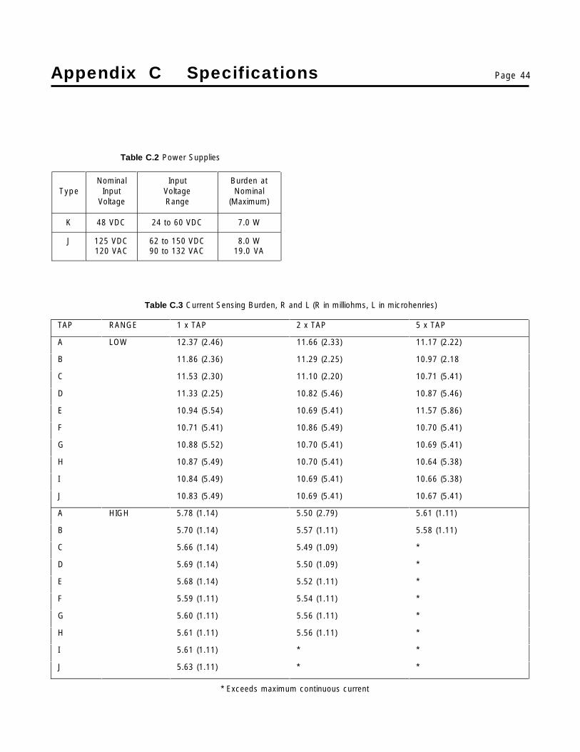
Appendix C Specifications Page 44
Table C.2 Power Supplies
TypeNominal
InputVoltage
InputVoltageRange
Burden atNominal
(Maximum)
K 48 VDC 24 to 60 VDC 7.0 W
J 125 VDC120 VAC
62 to 150 VDC90 to 132 VAC
8.0 W19.0 VA
Table C.3 Current Sensing Burden, R and L (R in milliohms, L in microhenries)
TAP RANGE 1 x TAP 2 x TAP 5 x TAP
A LOW 12.37 (2.46) 11.66 (2.33) 11.17 (2.22)
B 11.86 (2.36) 11.29 (2.25) 10.97 (2.18
C 11.53 (2.30) 11.10 (2.20) 10.71 (5.41)
D 11.33 (2.25) 10.82 (5.46) 10.87 (5.46)
E 10.94 (5.54) 10.69 (5.41) 11.57 (5.86)
F 10.71 (5.41) 10.86 (5.49) 10.70 (5.41)
G 10.88 (5.52) 10.70 (5.41) 10.69 (5.41)
H 10.87 (5.49) 10.70 (5.41) 10.64 (5.38)
I 10.84 (5.49) 10.69 (5.41) 10.66 (5.38)
J 10.83 (5.49) 10.69 (5.41) 10.67 (5.41)
A HIGH 5.78 (1.14) 5.50 (2.79) 5.61 (1.11)
B 5.70 (1.14) 5.57 (1.11) 5.58 (1.11)
C 5.66 (1.14) 5.49 (1.09) *
D 5.69 (1.14) 5.50 (1.09) *
E 5.68 (1.14) 5.52 (1.11) *
F 5.59 (1.11) 5.54 (1.11) *
G 5.60 (1.11) 5.56 (1.11) *
H 5.61 (1.11) 5.56 (1.11) *
I 5.61 (1.11) * *
J 5.63 (1.11) * *
* Exceeds maximum continuous current

Appendix C Specifications Page 45


Siemens Energy &Automation, Inc.Switchgear and Motor ControlBusinessP.O. Box 29503Raleigh, NC 27626-0503
Manual SG-9228-02 (Replaces SG-9228-01) ?M 0195xx Printed in U.S.A. © 1995 Siemens Energy & Automation, Inc.SIEMENS is a registered trademark of Siemens AG