installation - radio frequency systems plate installation 10 5.9 & 6.5 dual polarized feed...
TRANSCRIPT
These installation instructions are intended for use withStandard and High Performance 6 & 8 foot antennas -PA, PAF, PAX, DA, DAX, UA, UAX.
All required hardware for installing the antenna on thetower is supplied with the antenna. Other items such asmounting pipe, lifting slings, wrenches, etc., are notsupplied.
It is important that these instructions be read completelyand thoroughly before attempting to install the antenna onthe tower. Satisfactory operation cannot be guaranteedunless these instructions are followed carefully.
CABLE OF CONTENTS Page
Incoming Inspection 2Tools Required for Installation 2Steel Tower Mount Assembly 2Inst. of Elevation Pivot and Elevation Brackets 2Inst. of Elevation Adjust Rod 2Inst. of Steel Tower Mount 3Inst. of Hoisting Eyebolt 4Sway Bar Mounting Brackets 6Shroud Assembly and Installation 8Feed Installation 10Tuning Plate Installation 105.9 & 6.5 Dual Polarized Feed Installation 13Radome Installation for Shrouded Antennas 14Radome Installation for Standard Antennas 15Installation on Tower 16Sway Bar Assembly 19Elevation and Azimuth Adjustment 22Cross Polarization Nulling 22Feed Replacement 22
ILLUSTRATIONSFigure Page
1 Steel Tower Mount 32A Left-Hand Tower Mount Offset (standard) 42B Right-Hand Tower Mount Offset (alternate) 42C Left-Hand Tower Mount Offset (inverted) 42D Right-Hand Tower Mount Offset (inverted) 43 Tower Mount Brackets 54 Steel Tower Mount - Rear View 6,75-10 Shroud Assembly 8-911 Antenna Tuning Plate 1012-15 Antenna Feeds 1116 Feed Guying Details 1217 Feed Mounting Configurations 1218-20 5.9 & 6.5 Dual Polarized Feed Installation 1321,22 Radome Instl. for Shrouded Antennas 1423 Radome Instl. for Standard Antennas 1524 Hoisting Details 1625 Antenna Mounting - Side View 1726 PA 6 ft Azimuth Adjustment 1827 Sway Bar Assembly 1928 Sway Bar Attachment 20,21
Installation Instructions
No. 345 A
ECO 10225
(Eng. Dwg. 412646)
Microwave Parabolic Antennas6 & 8 Foot
Series - PA, PAF, PAL, PAX, DA, DAX, UA, UXA
PA, PAF, PAL,PAX
DA, DAX, UA,UXAHigh

TOOLS REQUIRED FOR INSTALLATION Socket Wrenches: 7/16", 1/2", 7/8", 1-1/16", 1-1/4" Deep Socket Wrench: 9/16" Phillips Screwdriver, medium size Adjustable Wrench, 12 "
Note: Use matching hex wrenches with socket wrenches.
STEEL TOWER MOUNT ASSEMBLYRefer to Figures 1, 2A, 2B, 2C, 2D
After uncrating the reflector and associated hardware andidentifying all pieces, proceed with assembly of the steeltower mount.
Note: The manner of steel tower mount attachment should be determined at this time.
Standard Tower Mount Installation: The vertical channelmember of the steel tower mount is offset to the left of thefeed mounting hole. This provides right-hand clearance ofthe feed and transmission line in reference to the mountingpipe.
Orientation of the tower mount in this configuration appearslike a "T" with a left-hand pipe offset, as viewed from theback of the reflector. See Figures 1 and 2A.
Alternate Tower Mount Installation: The vertical channelmember of the steel tower mount is offset to the right of thefeed mounting hole. This provides left-hand clearance of thefeed and transmission line in reference to the mounting pipe.
In this configuration, the upper section of the steel towermount is inverted and the lower section is mounted to theright side. Orientation of the tower mount in thisconfiguration appears like a "T" with a right-hand pipe offset,as viewed from the back of the reflector. See Figure 2B.
Inverted Installation for Antennas with ExtendedElevation Adjust Option: For downward deflectionrequirements of greater than 5 degrees, the antenna mustbe installed in an inverted position. The inverted positionplaces the elevation adjust rod at the top of the reflector andthe tower mount pivot brackets at the bottom.
For right-hand or left-hand tower mount offsets, the standardand alternate installation configuration is reversed.See Figures 2C and 2D.
1. Assemble the upper and lower tower mountsub-assemblies using 1/2-13 x 1-1/2 inch bolt sets asshown in Figure 1. Follow desired assemblyconfiguration as shown in illustrations 2A and 2B.
Note: Leave all bolts and nuts loose until tower mounthas been installed onto the antenna.
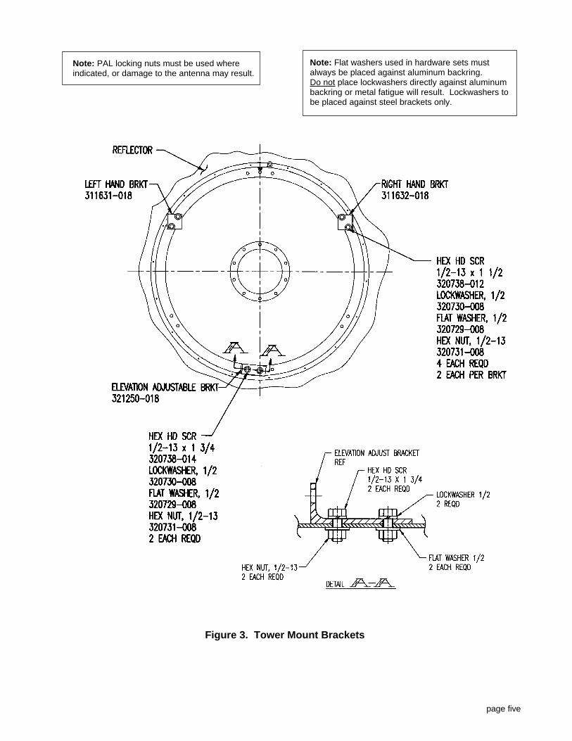
INSTALLATION OF PIVOT AND ELEVATIONTOWER MOUNT BRACKETSRefer to Figure 3 (page five)
Note: Flat washers used in hardware sets must always beplaced against aluminum backring. Do not placelockwashers directly against aluminum backring ormetal fatigue will result.
1. Attach the right and left hand pivot brackets to thereflector back ring with two each 1/2-13 x 1-1/2 inch boltflat washer, lockwasher and nut. Place the nuts and flatwashers under the lip of the reflector ring. Do nottighten bolts at this time.
2. Attach the elevation rod bracket to the base of thereflector back ring. The upright portion of the bracketshould be facing left. Use two each 1/2-13 x 1-3/4 inchbolt, flat washer, lock washer, and nut. The washersand nuts go under the lip of the reflector ring. Do nottighten bolts at this time.
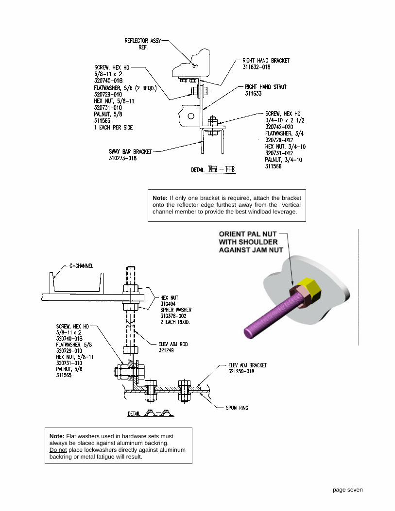
INSTALLATION OF ELEVATION ADJUST RODRefer to Figure 4 Detail A-A (page seven)
1. Secure the tab of elevation adjust rod to the elevationadjust bracket with one 5/8-11 x 2 inch bolt, nut, PALnut and flat washer. The bolt head must face the boltsholding the elevation bracket to the antenna. Do nottighten the bolt at this time.
2. Thread one 5/8-11 brass nut about half way down the5/8-11 threaded elevation adjust rod. Place onespherical washer onto the elevation rod with the radiusside toward the brass nut.
page two
INCOMING INSPECTIONCheck the packing list to be sure all material is received. In most cases packaging of 6 & 8 foot antennas consistof:
Shipping Crate No. 1a. Reflectorb. Feed (boxed)d. Tower Mount e. Tower Hardware (boxed)f. Sway Bars (no sway bar for 6 ft standard antennas)
Shipping Crate No. 2 a. Shroud, four section assembly.b. Radome and Shroud Hardware (boxed).
Optional Fiberglass Radome a. Conical Radome, single piece.b. Radome Hardware Kit (boxed).
Inspect the antenna for damage. It is particularlyimportant that the parabolic reflector be undamaged, freeof any dents or scratches. Also examine the boxcontaining the antenna feed. This is a precision partwhich must be carefully handled throughout installation,Any damage will degrade the antenna's performance, andrepairs to the feed are generally not possible In the field.
If damage is found, or if parts are missing, it should benoted on the carrier's delivery receipt. The carrier's officeand Cablewave Systems should be notified immediately.
Note: Foam packing located within non-pressurizedantenna feeds, and foam absorption material locatedinside shroud sections are not packing material and mustbe left intact for proper electrical performance of the

Figure 1. Steel Tower Mount
page three
INSTALLATION OF STEEL TOWER MOUNTRefer to Figure 4, Detail A-A & B-B (page six)
1. Place the steel tower mount on the reflector with the twostruts of the steel tower mount on the outside of the rightand left hand brackets. Square the steel tower mount sothat the elevation rod passes cleanly through theelevation hole in the steel tower mount.
2. Secure the tower mount to the right and left hand pivotbrackets with two 5/8-11 x 2 inch bolts, flat washers,nuts and PAL nuts. See Detail B-B (page seven).
3. Place a spherical washer onto the elevation rod with theflat side down. Thread one 5/8-11 brass nut onto theelevation rod. Hand tighten the two brass nuts. SeeDetail A-A (page seven).
4. Adjust the brass nuts up or down the elevation rod untilthe steel tower mount is parallel with the reflectorback-ring to obtain zero degrees elevation.
5. Tighten all bolts securely at this time and lock all nuts inplace with PAL locking nuts.
Note: Do not to drop the tower mount onto the reflectoror deformation of the parabolic reflector may

page four
Figure 2ALeft-Hand Tower Mount Offset
(standard)
Figure 2BRight-Hand Tower MountOffset
(alternate)
Figure 2CLeft-Hand Tower Mount Offset
(inverted reflector)
Figure 2DRight-Hand Tower MountOffset
(inverted reflector)
INSTALLATION OF HOISTING EYEBOLTRefer to Figure 2A & 2B
1. If necessary, relocate the hoisting eyebolt into one oftwo mounting holes (each end) in order to maintain theproper center of gravity when lifting the antenna to thetower.
For left-hand tower mount offset, locate the hoisting eyeboltto the left of center, and for right-hand offset, locate theeyebolt to the right of center. See Figures 2A and 2B.
page five
Figure 3. Tower Mount Brackets
Note: PAL locking nuts must be used whereindicated, or damage to the antenna may result.
Note: Flat washers used in hardware sets mustalways be placed against aluminum backring. Do not place lockwashers directly against aluminumbackring or metal fatigue will result. Lockwashers tobe placed against steel brackets only.
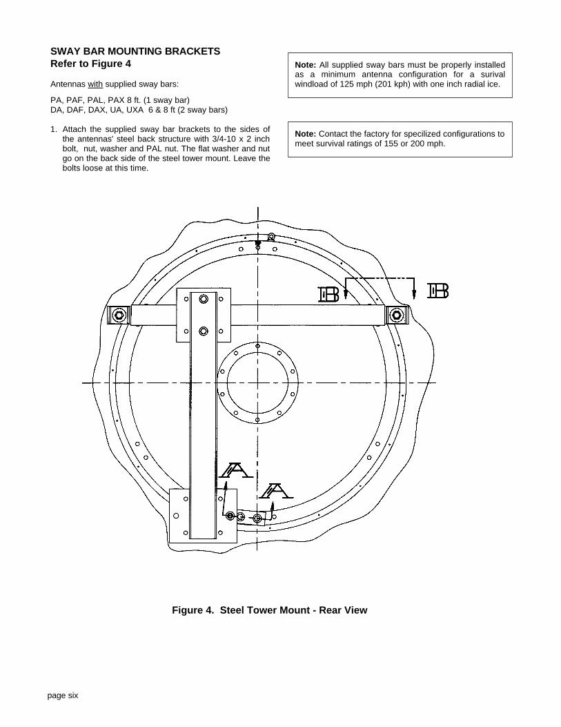
SWAY BAR MOUNTING BRACKETSRefer to Figure 4
Antennas with supplied sway bars:
PA, PAF, PAL, PAX 8 ft. (1 sway bar)DA, DAF, DAX, UA, UXA 6 & 8 ft (2 sway bars)
1. Attach the supplied sway bar brackets to the sides ofthe antennas' steel back structure with 3/4-10 x 2 inchbolt, nut, washer and PAL nut. The flat washer and nutgo on the back side of the steel tower mount. Leave thebolts loose at this time.
page six
Figure 4. Steel Tower Mount - Rear View
Note: All supplied sway bars must be properly installedas a minimum antenna configuration for a surivalwindload of 125 mph (201 kph) with one inch radial ice.
Note: Contact the factory for specilized configurations tomeet survival ratings of 155 or 200 mph.
page seven
Note: If only one bracket is required, attach the bracketonto the reflector edge furthest away from the verticalchannel member to provide the best windload leverage.
Note: Flat washers used in hardware sets mustalways be placed against aluminum backring. Do not place lockwashers directly against aluminumbackring or metal fatigue will result.
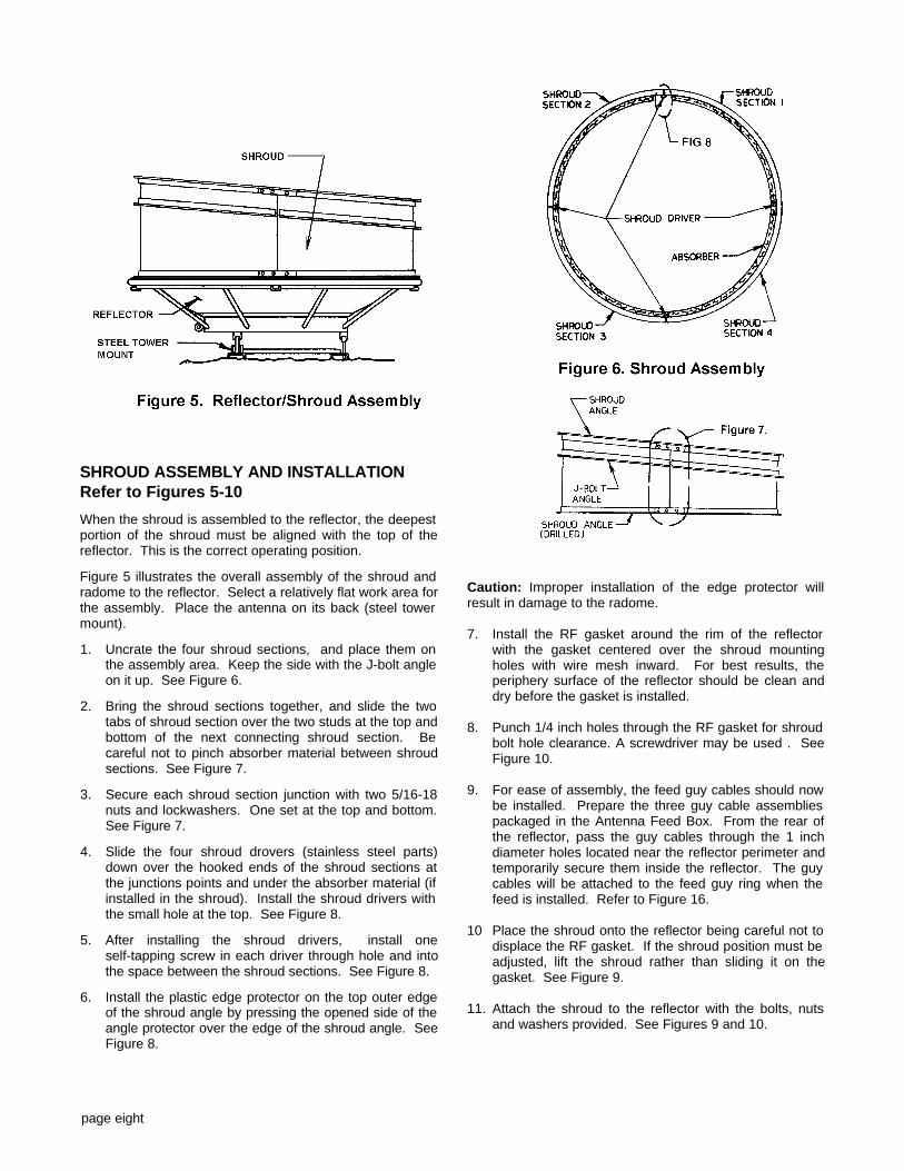
SHROUD ASSEMBLY AND INSTALLATIONRefer to Figures 5-10
When the shroud is assembled to the reflector, the deepestportion of the shroud must be aligned with the top of thereflector. This is the correct operating position.
Figure 5 illustrates the overall assembly of the shroud andradome to the reflector. Select a relatively flat work area forthe assembly. Place the antenna on its back (steel towermount).
1. Uncrate the four shroud sections, and place them onthe assembly area. Keep the side with the J-bolt angleon it up. See Figure 6.
2. Bring the shroud sections together, and slide the twotabs of shroud section over the two studs at the top andbottom of the next connecting shroud section. Becareful not to pinch absorber material between shroudsections. See Figure 7.
3. Secure each shroud section junction with two 5/16-18nuts and lockwashers. One set at the top and bottom.See Figure 7.
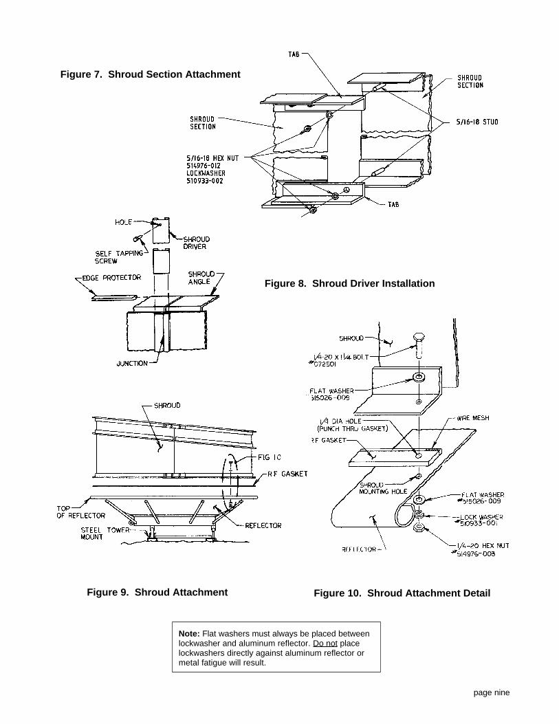
4. Slide the four shroud drovers (stainless steel parts)down over the hooked ends of the shroud sections atthe junctions points and under the absorber material (ifinstalled in the shroud). Install the shroud drivers withthe small hole at the top. See Figure 8.
5. After installing the shroud drivers, install oneself-tapping screw in each driver through hole and intothe space between the shroud sections. See Figure 8.
6. Install the plastic edge protector on the top outer edgeof the shroud angle by pressing the opened side of theangle protector over the edge of the shroud angle. SeeFigure 8.
Caution: Improper installation of the edge protector willresult in damage to the radome.
7. Install the RF gasket around the rim of the reflectorwith the gasket centered over the shroud mountingholes with wire mesh inward. For best results, theperiphery surface of the reflector should be clean anddry before the gasket is installed.
8. Punch 1/4 inch holes through the RF gasket for shroudbolt hole clearance. A screwdriver may be used . SeeFigure 10.
9. For ease of assembly, the feed guy cables should nowbe installed. Prepare the three guy cable assembliespackaged in the Antenna Feed Box. From the rear ofthe reflector, pass the guy cables through the 1 inchdiameter holes located near the reflector perimeter andtemporarily secure them inside the reflector. The guycables will be attached to the feed guy ring when thefeed is installed. Refer to Figure 16.
10 Place the shroud onto the reflector being careful not todisplace the RF gasket. If the shroud position must beadjusted, lift the shroud rather than sliding it on thegasket. See Figure 9.
11. Attach the shroud to the reflector with the bolts, nutsand washers provided. See Figures 9 and 10.
page eight
page nine
Figure 8. Shroud Driver Installation
Figure 7. Shroud Section Attachment
Figure 9. Shroud Attachment Figure 10. Shroud Attachment Detail
Note: Flat washers must always be placed betweenlockwasher and aluminum reflector. Do not placelockwashers directly against aluminum reflector ormetal fatigue will result.

FEED INSTALLATIONRefer To Figures 11 - 20
1 . Unpack the three guy wire assemblies, the feedclamping hardware and the antenna feed. Handle theantenna feed with extreme care. Always support bothends of the feed, and do not carry it by lifting at thecenter of the waveguide runs. Be particularly carefulwhen removing the feed from the expanded foampacking material. Do not use the feed as a pry bar toseparate the packing material.
2. If an antenna tuning plate has been supplied (packagedwith the antenna feed), it must be installed in thereflector before the feed. Install the tuning plate fromthe front of the reflector and fasten it to the feedmounting ring with 1/4 inch hardware. Refer to:Antenna Tuning Plate Installation - Figure 11.
3. The antenna must be in an upright position or nearupright position in order to install the antenna feed fromthe rear of the reflector.
4. Before continuing with feed installation, determine theoperating position of the feed for desired vertical orhorizontal polarization. Use the Top Views of Figures12 and 13 for installation positions of a single polarizedfeed. For the 2 GHz single polarized feed, use theseam on the rear of the feed mounting plate for properpolarization setting.
The dual polarized feed, oriented as shown in Figures14 and 15, is defined as the "normal" position and inthis position the radiation distribution envelope specified for the antenna will be duplicated. The leftand right sides of the pattern envelope can be reversedby rotating the feed 180o from the normal positionshown.
NOTE: For 5.9 & 6.5 GHz dual polarized feed installation,refer to page 13.
For 2 GHz dual polarized feed installation, use antennainstallation addendum No. 85 (Eng. Dwg. 412418).
5. Install the three guy wires through the (three) 1 inchdiameter holes in the rear of the reflector. Insert theantenna feed part-way through the feed mounting holeand then attach the three guy wires to the feed guy wirering. Close the S-hooks after securing the guy wires.Refer to Figure 16.
6. After guy wire attachment, extend the feed through thefeed mounting hole and onto the feed mounting ring.
7. Secure the feed into place with the 5/16 feed clamphardware provided. Refer to Figure 17.
CAUTION: The feed may only be rotated within a 90degree quadrant due to guy wire constraints. Ifnecessary, partially remove and relocate the feedaround a restricting guy wire to achieve desiredpolarization.
Always loosen the feed clamp washer/brackets beforeattempting cross polarization adjustment.
CAUTION: All feed guy wires are set at the factory to theproper length for positioning the feed at the reflector'sfocal point. Check locknuts on the guy wires to insuretightness.
If adjustment of the feed guy wires is necessary afterthe antenna is installed on the tower, always slackenthe cable at one stud and then take up the slack at anopposing stud. Use care not to over tighten the feedguy cables as damage to the feed will result.
ANTENNA TUNING PLATEINSTALLATIONFigure 11
(For antennas with Tuning Plates)
1. Remove five alternate 1/4-20 nuts,bolts and lockwashers and washersfrom the feed mounting ring. Savethe nuts and lockwashers.
2. Assemble the supplied 1/4-20 bolts,and spacers (if spacers are supplied)to the tuning plate as shown in theillustration.
Note: Feed Spacers may not look asillustrated. Some spacers may looklike washers. Spacer requirementsare operating frequency dependent.
3. Install the tuning plate from the frontof the reflector and fasten it to thefeed mounting ring with the 1/4-20nuts and lockwashers previouslyremoved.
page ten
Figure 11. Antenna Tuning Plate

page eleven
The physical configurations of the single and dualpolarized waveguide feed are dependent upon operatingfrequency and may vary slightly from the feeds illustrated.
Figure 12. Single Polarized Waveguide Feed Figure 13. Single Polarized 2 GHz Feed
Figure 14. Dual Polarized Waveguide Feed

page twelve
Guy Wire Detail
Figure 16. Feed Guying
Figure 17.Feed Mounting

Figure 18.
Figure 19.Figure 20.
5.9 & 6.5 DUAL POLARIZED FEEDINSTALLATIONFigures 16 - 20
The following steps apply only to dual polarized feeds with a9" mounting hole (5.9 & 6.5 GHz dual polarized feeds).
1. Remove the feed guy wire from the feed polarizerassembly by slipping it over the O-ring securing it to thepolarizer end plug. Refer to Figure 16.
2. Feed the three guy wires through the three 1 inchdiameter holes from the rear of the reflector and attachthem to the previously removed feed guy wire ring.Close the S-hooks on the feed guy wire ring aftersecuring the guy wires. Refer to Figure 16.
3. Refer to Figures 18, 19, and 20 for the following steps:After attaching the guy wires to the guy wire ring, insertthe feed polarizer into the feed mounting hole - back endwith end plug first into the nine inch hole. Next carefullyswing the front end of the polarizer with mylar radomethrough the feed mounting hole and into the reflector.
After the feed polarizer has cleared the feed mountinghole, insert the feed part way into the reflector and attachthe feed guy wire ring with guy wires onto the polarizerend plug. Extend the feed the remainder of the way intothe reflector and onto the feed mounting ring. Secure thefeed assembly with the feed clamp brackets provided.Refer to Figure 17.
page thirteen

RADOME INSTALLATIONFOR SHROUDED ANTENNAS
Refer To Figures 21 & 22
1. Install all J-bolts assemblies into the holes locatedon the perimeter mounted J-bolt angle. This maybe done by passing the hooked end of the J-boltthrough the hole in the angle from the bottomside.
2. Insert one J-bolt clip into each tab on the radome.Secure each J-bolt clip in place with the twopush-on plastic caps provided.
3. Place the radome over the shroud with the sidemarked "TOP" to the outside of the shroud.
4. Orient the radome so that the "TOP" mark on theradome is aligned with the top of the shroud (thejunction point at the deepest part of the shroud).
5. Hook each J-bolt onto each radome J-bolt clip.Tighten each J-bolt nut until all springs arecompressed to a dimension of 4 inches. Tightenthe springs alternately to insure that the radomeremains centered on the shroud. After tensioningof the radome is completed, tighten the jam nuton each J-bolt to secure the spring adjustment.
page fourteen
Figure 21. Radome Assembly
Figure 22. J-Bolt Assembly

OPTIONAL RADOME INSTALLATIONFOR STANDARD ANTENNAS(PA, PAF, PAL, PAX)
Refer To Figures 23
The radome may be installed before the antenna feed hasbeen installed.
1. Place the antenna reflector face up on level ground forinstallation of the radome. Do not support the antennaby setting it on the lip of the reflector.
2. Secure the radome to the reflector with 1/4-20 x 1-1/4inch bolts, flat washers and self-locking nuts. Placeone flat washer between the bolt head and radome, andone flat washer between the nut and reflector flange.See Figure 23, Detail A.
CAUTION: Do not lift the radome with mechanical devicesor damage may result. Lift only by hand using care notto deform the radome.
If the antenna feed has not been installed, be sure toinsert the three guy wires through the three 1 inchdiameter holes from the rear of the reflector. Tie theguy wires together with cord so they may be attachedwhen the feed is installed.
page fifteen
Figure 23.Conical Radomes
Note: Flat washers must always be placed betweenlockwasher and aluminum reflector. Do not placelockwashers directly against aluminum reflector ormetal fatigue will result.
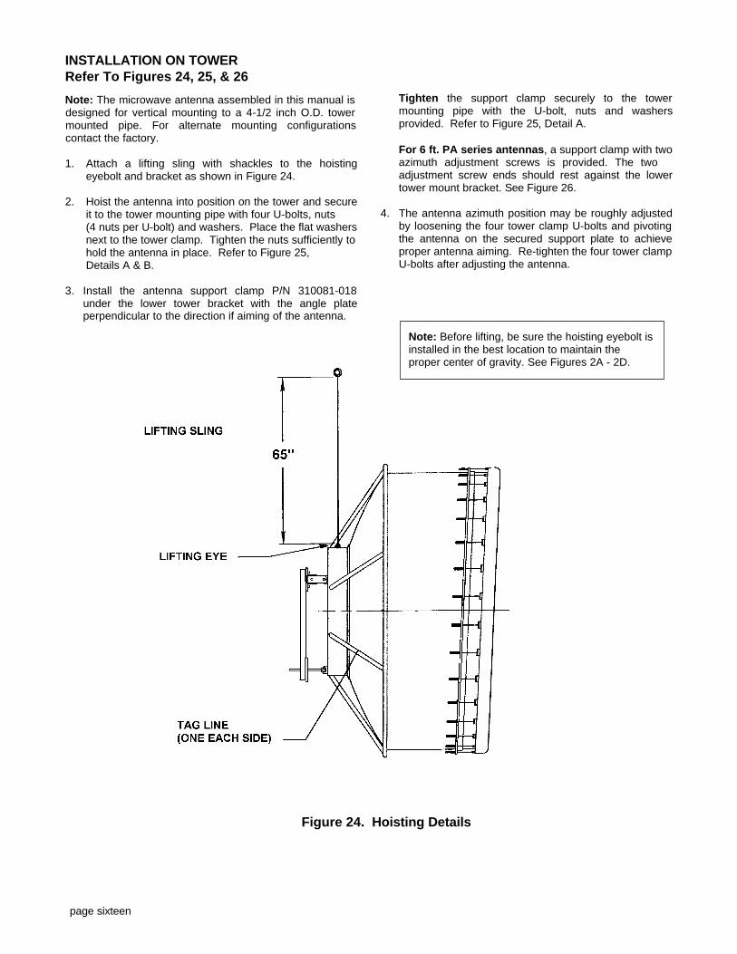
INSTALLATION ON TOWERRefer To Figures 24, 25, & 26
Note: The microwave antenna assembled in this manual isdesigned for vertical mounting to a 4-1/2 inch O.D. towermounted pipe. For alternate mounting configurationscontact the factory.
1. Attach a lifting sling with shackles to the hoistingeyebolt and bracket as shown in Figure 24.
2. Hoist the antenna into position on the tower and secureit to the tower mounting pipe with four U-bolts, nuts (4 nuts per U-bolt) and washers. Place the flat washersnext to the tower clamp. Tighten the nuts sufficiently tohold the antenna in place. Refer to Figure 25,Details A & B.
3. Install the antenna support clamp P/N 310081-018under the lower tower bracket with the angle plateperpendicular to the direction if aiming of the antenna.
Tighten the support clamp securely to the towermounting pipe with the U-bolt, nuts and washersprovided. Refer to Figure 25, Detail A.
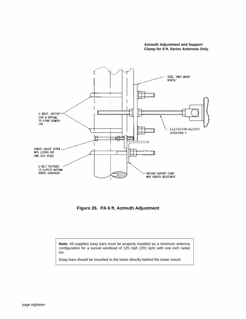
For 6 ft. PA series antennas, a support clamp with twoazimuth adjustment screws is provided. The two adjustment screw ends should rest against the lowertower mount bracket. See Figure 26.
4. The antenna azimuth position may be roughly adjustedby loosening the four tower clamp U-bolts and pivotingthe antenna on the secured support plate to achieveproper antenna aiming. Re-tighten the four tower clampU-bolts after adjusting the antenna.
page sixteen
Figure 24. Hoisting Details
Note: Before lifting, be sure the hoisting eyebolt isinstalled in the best location to maintain theproper center of gravity. See Figures 2A - 2D.

Detail "B"Upper Tower Clamp
Detail "A"Lower Tower Clamp
Figure 25.Antenna Mounting - Side View
page seventeen
page eighteen
Figure 26. PA 6 ft. Azimuth Adjustment
Azimuth Adjustment and SupportClamp for 6 ft. Series Antennas Only.
Note: All supplied sway bars must be properly installed as a minimum antennaconfiguration for a surival windload of 125 mph (201 kph) with one inch radialice.
Sway bars should be mounted to the tower directly behind the tower mount

SWAY BAR ASSEMBLYRefer to Figures 27 & 28
After the antenna has been installed on the tower androughly aimed, the antenna sway bar assembly is attachedto the antenna. One sway bar assembly is supplied withstandard antennas, and two sway bar assemblies aresupplied with high performance (shrouded) antennas.
1. At ground level, assemble two U-bolts (16) to the swaybar clamp (11), and one U-bolt (16) to the azimuthadjust angle (15). Assemble with four nuts and twowashers per U-bolt. Temporarily thread the nuts on onlya few turns.
2. Attach the sway bar clamp angle (17) to the sway barclamp with a 3/4-10 x 2-1/2 inch bolt, nut and washer.The bolt head must be on the clamp side. Use the rearhole in the clamp angle (17) if the antenna will bemounted higher than the sway bar; and use the fronthole if the antenna will be mounted lower than the swaybar.
3. Slide the azimuth adjust angle and sway bar clampassembly onto the sway bar (8). Tighten all U-bolts onthe sway bar assembly.
4. Attach the sway bar mounting brackets (4D) to bothsides of the antenna's steel back-structure with 3/4-10 x2 inch bolts, washers, nuts and PAL locking nuts.Temporarily leave the bolts loose.
5. Hoist the sway bar into position on the installedantenna. Attach the sway bar to the sway bar mountingbracket (4D) with 3/4-10 x 4-1/2 inch bolt, washer, nutand PAL locking nuts. See Detail B-B.
6. Position the sway bar onto the pre-installed towermounting angle (6B) - customer supplied.
7. Loosen the U-bolts on the sway bar clamp (11) and onthe azimuth adjust angle (15). Slide the sway bar clampassembly into position so that the sway bar clamp angle(17) can be attached to the tower mounting angle (6B).Attach the sway bar clamp angle with a 3/4-10 x 2-1/2inch bolt, nut, washer and PAL locking nut.
8. Securely tighten all antenna sway bar hardware, and besure to lock all nuts in place with PAL locking nuts.
This completes installation of one sway bar assembly. If theantenna is supplied with two sway bar assemblies, repeatsteps 1 through 8. Note; only one azimuth adjust assemblyis used on an antenna.
page nineteen
Figure 27. Sway Bar Assembly
Note: PAL locking nuts must be used whereindicated, or damage to the antenna may result.
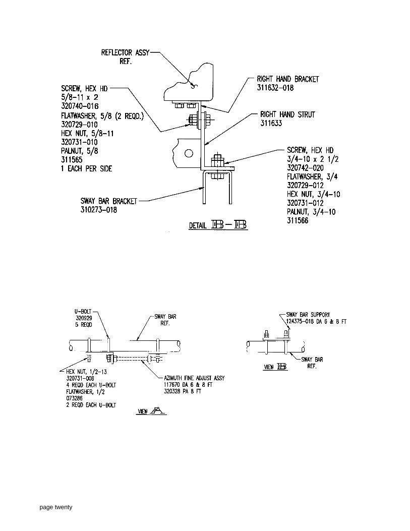
page twenty
page twenty-one
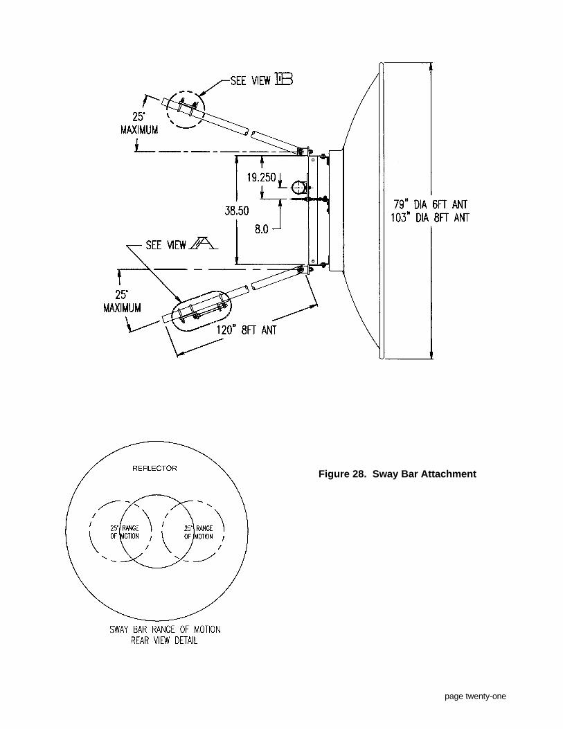
Figure 28. Sway Bar Attachment
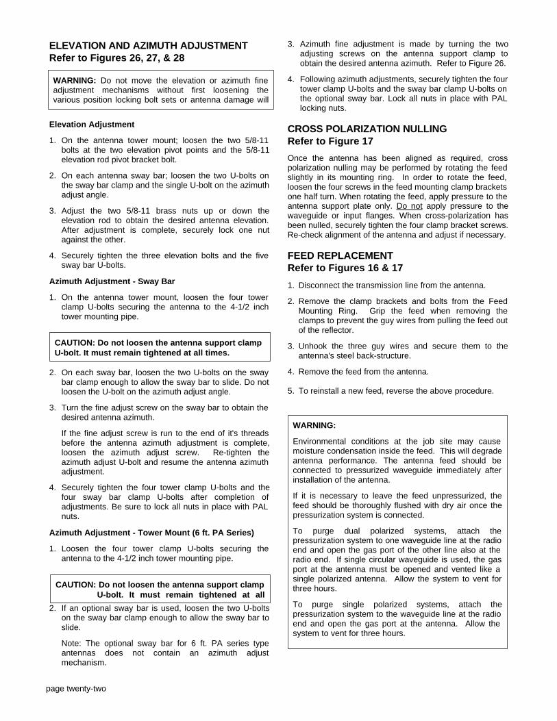
ELEVATION AND AZIMUTH ADJUSTMENTRefer to Figures 26, 27, & 28
Elevation Adjustment
1. On the antenna tower mount; loosen the two 5/8-11bolts at the two elevation pivot points and the 5/8-11elevation rod pivot bracket bolt.
2. On each antenna sway bar; loosen the two U-bolts onthe sway bar clamp and the single U-bolt on the azimuthadjust angle.
3. Adjust the two 5/8-11 brass nuts up or down theelevation rod to obtain the desired antenna elevation.After adjustment is complete, securely lock one nutagainst the other.
4. Securely tighten the three elevation bolts and the fivesway bar U-bolts.
Azimuth Adjustment - Sway Bar
1. On the antenna tower mount, loosen the four towerclamp U-bolts securing the antenna to the 4-1/2 inchtower mounting pipe.
2. On each sway bar, loosen the two U-bolts on the swaybar clamp enough to allow the sway bar to slide. Do notloosen the U-bolt on the azimuth adjust angle.
3. Turn the fine adjust screw on the sway bar to obtain thedesired antenna azimuth.
If the fine adjust screw is run to the end of it's threadsbefore the antenna azimuth adjustment is complete,loosen the azimuth adjust screw. Re-tighten theazimuth adjust U-bolt and resume the antenna azimuthadjustment.
4. Securely tighten the four tower clamp U-bolts and thefour sway bar clamp U-bolts after completion ofadjustments. Be sure to lock all nuts in place with PALnuts.
Azimuth Adjustment - Tower Mount (6 ft. PA Series)
1. Loosen the four tower clamp U-bolts securing theantenna to the 4-1/2 inch tower mounting pipe.
2. If an optional sway bar is used, loosen the two U-boltson the sway bar clamp enough to allow the sway bar toslide.
Note: The optional sway bar for 6 ft. PA series typeantennas does not contain an azimuth adjustmechanism.
3. Azimuth fine adjustment is made by turning the twoadjusting screws on the antenna support clamp toobtain the desired antenna azimuth. Refer to Figure 26.
4. Following azimuth adjustments, securely tighten the fourtower clamp U-bolts and the sway bar clamp U-bolts onthe optional sway bar. Lock all nuts in place with PALlocking nuts.
CROSS POLARIZATION NULLINGRefer to Figure 17
Once the antenna has been aligned as required, crosspolarization nulling may be performed by rotating the feedslightly in its mounting ring. In order to rotate the feed,loosen the four screws in the feed mounting clamp bracketsone half turn. When rotating the feed, apply pressure to theantenna support plate only. Do not apply pressure to thewaveguide or input flanges. When cross-polarization hasbeen nulled, securely tighten the four clamp bracket screws.Re-check alignment of the antenna and adjust if necessary.
FEED REPLACEMENTRefer to Figures 16 & 17
1. Disconnect the transmission line from the antenna.
2. Remove the clamp brackets and bolts from the FeedMounting Ring. Grip the feed when removing theclamps to prevent the guy wires from pulling the feed outof the reflector.
3. Unhook the three guy wires and secure them to theantenna's steel back-structure.
4. Remove the feed from the antenna.
5. To reinstall a new feed, reverse the above procedure.
page twenty-two
WARNING: Do not move the elevation or azimuth fineadjustment mechanisms without first loosening thevarious position locking bolt sets or antenna damage will
CAUTION: Do not loosen the antenna support clamp U-bolt. It must remain tightened at all times.
CAUTION: Do not loosen the antenna support clampU-bolt. It must remain tightened at all
WARNING:
Environmental conditions at the job site may causemoisture condensation inside the feed. This will degradeantenna performance. The antenna feed should beconnected to pressurized waveguide immediately afterinstallation of the antenna.
If it is necessary to leave the feed unpressurized, thefeed should be thoroughly flushed with dry air once thepressurization system is connected.
To purge dual polarized systems, attach thepressurization system to one waveguide line at the radioend and open the gas port of the other line also at theradio end. If single circular waveguide is used, the gasport at the antenna must be opened and vented like asingle polarized antenna. Allow the system to vent forthree hours.
To purge single polarized systems, attach thepressurization system to the waveguide line at the radioend and open the gas port at the antenna. Allow thesystem to vent for three hours.
page twenty-three
The Seller warrants that any equipment sold hereundershall be free from defects in materials and workmanship forone (1) year after shipment. To make a claim under thiswarranty, the Buyer must notify the Seller in writingimmediately after the Buyer discovers or should havediscovered the defect and receive authorization to returnthe defective equipment to Seller. Seller's sole andexclusive liability shall be to repair or replace the defectiveequipment and ship it back to the Buyer. This warrantydoes not apply to defects not caused by the Seller, such asacts of God, abuse, improper installation or alteration.
Equipment supplied as a warranty replacement shall bewarranted for the remainder of the original warranty period.
No express warranties and no implied warranties whetherof merchantability or fitness for any particular purpose orotherwise (except as to title) other than those set forthabove shall apply to equipment sold by Seller and nowaiver, alteration or modification of the foregoing shall bebinding against Seller unless signed by an executive officerof Seller.
WARRANTY
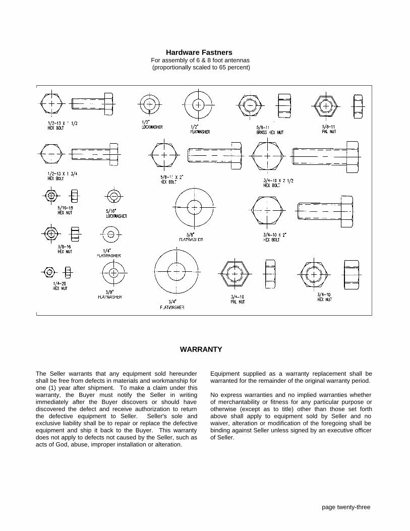
Hardware Fastners For assembly of 6 & 8 foot antennas (proportionally scaled to 65 percent)

INSTALLATION INSTRUCTIONS No. 345 A
Series - PA, PAF, PAL, PAX, DA, DAX, UA, UXA
6 & 8 Foot Microwave Parabolic Antennas
As specialists in microwave antennas and RF transmissionlines, Cablewave Systems, a division of Radio FrequencySystems, Inc., was founded in 1973 by Kabelmetal A.G. ofWest Germany and the Phelps Dodge CommunicationsCompany of the USA.
Cablewave Systems is dedicated to the development andmanufacture of high quality products for the transmissionof RF and microwave signals. Manufacturing in a TotalQuality environment, our products include: aluminumparabolic microwave antennas, television and FMbroadcast antennas, Flexwell coaxial cables and ellipticalwaveguides, rigid coaxial transmission line, connectors,pressurization equipment, installation accessories andrelated field services. Cablewave products serve theindustrial, telephone, broadcast and military markets for thetransmission of voice, video, and digital information.
The main office and production facility is located in NorthHaven, Connecticut (USA), and occupies a modern127,000 foot plant on over twelve acres, housingmanufacturing, research and sales offices. Engineeringfacilities include an on-site anechoic chamber, mechanicsload simulator and two fully equipped antenna test ranges.
All products are manufactured under stringent qualitycontrol inspection standards per MIL-1-45208 and meetapplicable EIA and FCC standards.
Product specifications are subject to change without notice.
Cablewave Systems Federal Supply Code Number 16733.