installation & tech manual - mtp storemtpstore.co.uk/files/_f_/113_e69c3a_mrc instal.pdf ·...
TRANSCRIPT

55008351-20
INSTALLATION & TECHNICAL MANUAL
MARSTAIR REFRIGERATION CONDENSING UNITS (MRC+)

2/27 55008351-20
CONTENTS PAGE DIMENSIONS & WEIGHTS (packed & unpacked) & SPECIFICATION. 3 PERFORMANCE DATA. 4-9 MOUNTING, DIMENSIONS & WEIGHTS. 10-11 PIPEWORK. 11-12 ELECTRICAL & FUSES. 12-14 REFRIGERANT. 15-16 END OF LIFE REQUIRMENTS. 17 ECO DESIGN INFORMATION TABLES. 18-25 COMPONENT IDENTIFICATION MRC+. 26-27
1. TEV LTD recommend that personnel working on this equipment be skilled and fully conversant
with the appropriate Refrigeration and Electrical practices and have sound knowledge of current Industrial Safe Working practices.
2. These units are supplied with a holding charge of oxygen free nitrogen and polyolester oil.
Do not mix oils or refrigerants.
3. These units when installed contain live electrical components, moving parts and refrigerant under pressure. Always site out of reach of children and protect from vandalism.
4. The data plate only gives information for the outdoor unit. For system details add input power and
current of indoor and outdoor unit, including any heater load. 5. FUSES - for recommended fuse size see page 12. 6. The refrigerant used should be identified by locating a refrigerant label on the unit case
INDEX
GENERAL
NOTE IF MECHANICAL PUMP DOWN OPERATION IS REQUIRED CONNECT A LINK WIRE
BETWEEN TERMINALS L1 & 3. IF THIS LINK IS USED THEN TERMINAL 5 CAN NOT BE USED AS AN ALARM FACILITY
3/27 55008351-20
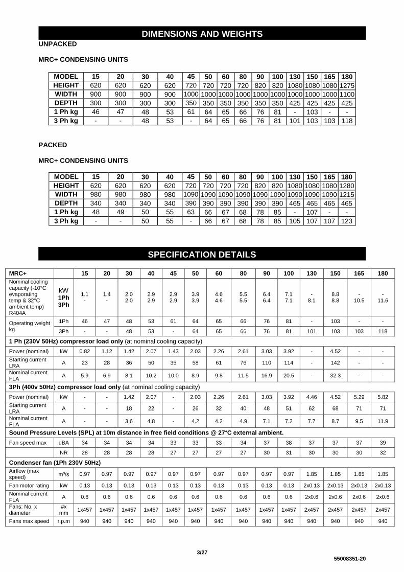
UNPACKED MRC+ CONDENSING UNITS
MODEL
15 20 30 40 45 50 60 80 90 100 130 150 165 180
HEIGHT mm
620 620 620 620 720 720 720 720 820 820 1080 1080 1080 1275
WIDTH mm
900 900 900 900 1000 1000 1000 1000 1000 1000 1000 1000 1000 1100
DEPTH mm
300 300 300 300 350 350 350 350 350 350 425 425 425 425
1 Ph kg
46 47 48 53 61 64 65 66 76 81 - 103 - -
3 Ph kg - - 48 53 - 64 65 66 76 81 101 103 103 118
PACKED MRC+ CONDENSING UNITS
MODEL
15 20 30 40 45 50 60 80 90 100 130 150 165 180
HEIGHT mm
620 620 620 620 720 720 720 720 820 820 1080 1080 1080 1280
WIDTH mm
980 980 980 980 1090 1090 1090 1090 1090 1090 1090 1090 1090 1215
DEPTH mm
340 340 340 340 390 390 390 390 390 390 465 465 465 465
1 Ph kg
48 49 50 (43*)
55 (47*)
63 66 67 68 78 85 - 107 - -
3 Ph kg - - 50 55 - 66 67 68 78 85 105 107 107 123
MRC+ 15 20 30 40 45 50 60 80 90 100 130 150 165 180
Nominal cooling capacity (-10°C evaporating temp & 32°C ambient temp) R404A
kW 1Ph 3Ph
1.1 -
1.4 -
2.0 2.0
2.9 2.9
2.9 2.9
3.9 3.9
4.6 4.6
5.5 5.5
6.4 6.4
7.1 7.1
- 8.1
8.8 8.8
- 10.5
- 11.6
Operating weight kg
1Ph 46 47 48 53 61 64 65 66 76 81 - 103 - -
3Ph - - 48 53 - 64 65 66 76 81 101 103 103 118
1 Ph (230V 50Hz) compressor load only (at nominal cooling capacity)
Power (nominal) kW 0.82 1.12 1.42 2.07 1.43 2.03 2.26 2.61 3.03 3.92 - 4.52 - -
Starting current LRA
A 23 28 36 50 35 58 61 76 110 114 - 142 - -
Nominal current FLA
A 5.9 6.9 8.1 10.2 10.0 8.9 9.8 11.5 16.9 20.5 - 32.3 - -
3Ph (400v 50Hz) compressor load only (at nominal cooling capacity)
Power (nominal) kW - - 1.42 2.07 - 2.03 2.26 2.61 3.03 3.92 4.46 4.52 5.29 5.82
Starting current LRA
A - - 18 22 - 26 32 40 48 51 62 68 71 71
Nominal current FLA
A - - 3.6 4.8 - 4.2 4.2 4.9 7.1 7.2 7.7 8.7 9.5 11.9
Sound Pressure Levels (SPL) at 10m distance in free field conditions @ 27°C external ambient.
Fan speed max dBA 34 34 34 34 33 33 33 34 37 38 37 37 37 39
NR 28 28 28 28 27 27 27 27 30 31 30 30 30 32
Condenser fan (1Ph 230V 50Hz)
Airflow (max speed)
m³/s 0.97 0.97 0.97 0.97 0.97 0.97 0.97 0.97 0.97 0.97 1.85 1.85 1.85 1.85
Fan motor rating kW 0.13 0.13 0.13 0.13 0.13 0.13 0.13 0.13 0.13 0.13 2x0.13 2x0.13 2x0.13 2x0.13
Nominal current FLA
A 0.6 0.6 0.6 0.6 0.6 0.6 0.6 0.6 0.6 0.6 2x0.6 2x0.6 2x0.6 2x0.6
Fans: No. x diameter
#x mm
1x457 1x457 1x457 1x457 1x457 1x457 1x457 1x457 1x457 1x457 2x457 2x457 2x457 2x457
Fans max speed r.p.m 940 940 940 940 940 940 940 940 940 940 940 940 940 940
DIMENSIONS AND WEIGHTS
SPECIFICATION DETAILS
4/27 55008351-20
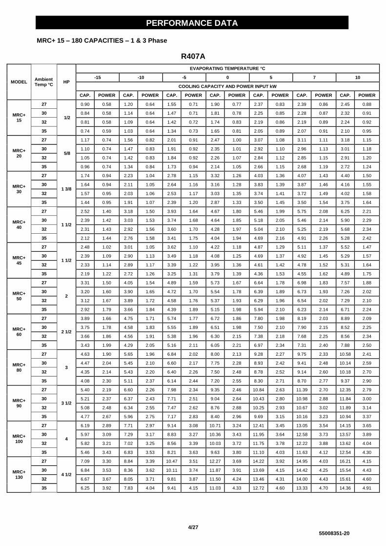
MRC+ 15 – 180 CAPACITIES – 1 & 3 Phase
R407A
MODEL Ambient Temp °C
HP
EVAPORATING TEMPERATURE °C
-15 -10 -5 0 5 7 10
COOLING CAPACITY AND POWER INPUT kW
CAP. POWER CAP. POWER CAP. POWER CAP. POWER CAP. POWER CAP. POWER CAP. POWER
MRC+ 15
27
1/2
0.90 0.58 1.20 0.64 1.55 0.71 1.90 0.77 2.37 0.83 2.39 0.86 2.45 0.88
30 0.84 0.58 1.14 0.64 1.47 0.71 1.81 0.78 2.25 0.85 2.28 0.87 2.32 0.91
32 0.81 0.58 1.09 0.64 1.42 0.72 1.74 0.83 2.19 0.86 2.19 0.89 2.24 0.92
35 0.74 0.59 1.03 0.64 1.34 0.73 1.65 0.81 2.05 0.89 2.07 0.91 2.10 0.95
MRC+ 20
27
5/8
1.17 0.74 1.56 0.82 2.01 0.91 2.47 1.00 3.07 1.08 3.11 1.11 3.18 1.15
30 1.10 0.74 1.47 0.83 1.91 0.92 2.35 1.01 2.92 1.10 2.96 1.13 3.01 1.18
32 1.05 0.74 1.42 0.83 1.84 0.92 2.26 1.07 2.84 1.12 2.85 1.15 2.91 1.20
35 0.96 0.74 1.34 0.84 1.73 0.94 2.14 1.05 2.66 1.15 2.68 1.19 2.72 1.24
MRC+ 30
27
1 3/8
1.74 0.94 2.23 1.04 2.78 1.15 3.32 1.26 4.03 1.36 4.07 1.43 4.40 1.50
30 1.64 0.94 2.11 1.05 2.64 1.16 3.16 1.28 3.83 1.39 3.87 1.46 4.16 1.55
32 1.57 0.95 2.03 1.06 2.53 1.17 3.03 1.35 3.74 1.41 3.72 1.49 4.02 1.58
35 1.44 0.95 1.91 1.07 2.39 1.20 2.87 1.33 3.50 1.45 3.50 1.54 3.75 1.64
MRC+ 40
27
1 1/2
2.52 1.40 3.18 1.50 3.93 1.64 4.67 1.80 5.46 1.99 5.75 2.08 6.25 2.21
30 2.39 1.42 3.03 1.53 3.74 1.68 4.64 1.85 5.18 2.05 5.46 2.14 5.90 2.29
32 2.31 1.43 2.92 1.56 3.60 1.70 4.28 1.97 5.04 2.10 5.25 2.19 5.68 2.34
35 2.12 1.44 2.76 1.58 3.41 1.75 4.04 1.94 4.69 2.16 4.91 2.26 5.28 2.42
MRC+ 45
27
1 1/2
2.48 1.02 3.01 1.05 3.62 1.10 4.22 1.18 4.87 1.29 5.11 1.37 5.52 1.47
30 2.39 1.09 2.90 1.13 3.49 1.18 4.08 1.25 4.69 1.37 4.92 1.45 5.29 1.57
32 2.33 1.14 2.89 1.17 3.39 1.22 3.95 1.36 4.61 1.42 4.78 1.52 5.31 1.64
35 2.19 1.22 2.72 1.26 3.25 1.31 3.79 1.39 4.36 1.53 4.55 1.62 4.89 1.75
MRC+ 50
27
2
3.31 1.50 4.05 1.54 4.89 1.59 5.73 1.67 6.64 1.78 6.98 1.83 7.57 1.88
30 3.20 1.60 3.90 1.65 4.72 1.70 5.54 1.78 6.39 1.89 6.73 1.93 7.26 2.02
32 3.12 1.67 3.89 1.72 4.58 1.76 5.37 1.93 6.29 1.96 6.54 2.02 7.29 2.10
35 2.92 1.79 3.66 1.84 4.39 1.89 5.15 1.98 5.94 2.10 6.23 2.14 6.71 2.24
MRC+ 60
27
2 1/2
3.89 1.66 4.75 1.71 5.74 1.77 6.72 1.86 7.80 1.98 8.19 2.03 8.89 2.09
30 3.75 1.78 4.58 1.83 5.55 1.89 6.51 1.98 7.50 2.10 7.90 2.15 8.52 2.25
32 3.66 1.86 4.56 1.91 5.38 1.96 6.30 2.15 7.38 2.18 7.68 2.25 8.56 2.34
35 3.43 1.99 4.29 2.05 5.16 2.11 6.05 2.21 6.97 2.34 7.31 2.40 7.88 2.50
MRC+ 80
27
3
4.63 1.90 5.65 1.96 6.84 2.02 8.00 2.13 9.28 2.27 9.75 2.33 10.58 2.41
30 4.47 2.04 5.45 2.10 6.60 2.17 7.75 2.28 8.93 2.42 9.41 2.48 10.14 2.59
32 4.35 2.14 5.43 2.20 6.40 2.26 7.50 2.48 8.78 2.52 9.14 2.60 10.18 2.70
35 4.08 2.30 5.11 2.37 6.14 2.44 7.20 2.55 8.30 2.71 8.70 2.77 9.37 2.90
MRC+ 90
27
3 1/2
5.40 2.19 6.60 2.26 7.98 2.34 9.35 2.46 10.84 2.63 11.39 2.70 12.35 2.79
30 5.21 2.37 6.37 2.43 7.71 2.51 9.04 2.64 10.43 2.80 10.98 2.88 11.84 3.00
32 5.08 2.48 6.34 2.55 7.47 2.62 8.76 2.88 10.25 2.93 10.67 3.02 11.89 3.14
35 4.77 2.67 5.96 2.75 7.17 2.83 8.40 2.96 9.69 3.15 10.16 3.23 10.94 3.37
MRC+ 100
27
4
6.19 2.89 7.71 2.97 9.14 3.08 10.71 3.24 12.41 3.45 13.05 3.54 14.15 3.65
30 5.97 3.09 7.29 3.17 8.83 3.27 10.36 3.43 11.95 3.64 12.58 3.73 13.57 3.89
32 5.82 3.21 7.02 3.25 8.56 3.39 10.03 3.72 11.75 3.78 12.22 3.88 13.62 4.04
35 5.46 3.43 6.83 3.53 8.21 3.63 9.63 3.80 11.10 4.03 11.63 4.12 12.54 4.30
MRC+ 130
27
4 1/2
7.09 3.30 8.84 3.39 10.47 3.51 12.27 3.69 14.22 3.92 14.95 4.03 16.21 4.15
30 6.84 3.53 8.36 3.62 10.11 3.74 11.87 3.91 13.69 4.15 14.42 4.25 15.54 4.43
32 6.67 3.67 8.05 3.71 9.81 3.87 11.50 4.24 13.46 4.31 14.00 4.43 15.61 4.60
35 6.25 3.92 7.83 4.04 9.41 4.15 11.03 4.33 12.72 4.60 13.33 4.70 14.36 4.91
PERFORMANCE DATA

5/27 55008351-20
MODEL Ambient Temp °C
HP
EVAPORATING TEMPERATURE °C
-15 -10 -5 0 5 7 10
COOLING CAPACITY AND POWER INPUT kW
CAP. POWER CAP. POWER CAP. POWER CAP. POWER CAP. POWER CAP. POWER CAP. POWER
MRC+ 150
27
5
7.74 3.34 9.64 3.44 11.43 3.56 13.38 3.74 15.51 3.97 16.30 4.08 17.68 4.20
30 7.46 3.57 9.11 3.67 11.03 3.78 12.95 3.96 14.93 4.20 15.72 4.30 16.95 4.49
32 7.28 3.71 8.78 3.76 10.70 3.92 12.54 4.29 14.68 4.36 15.28 4.48 17.02 4.66
35 6.82 3.97 8.54 4.09 10.26 4.20 12.03 4.39 13.87 4.66 14.54 4.76 15.67 4.97
MRC+ 165
27
6
9.23 3.89 11.50 4.00 13.63 4.14 15.96 4.35 18.51 4.63 19.45 4.76 21.09 4.90
30 8.90 4.16 10.87 4.28 13.16 4.41 15.44 4.62 17.81 4.91 18.76 5.03 20.22 5.25
32 8.68 4.33 10.47 4.38 12.76 4.58 14.96 5.02 17.51 5.10 18.22 5.24 20.31 5.45
35 8.14 4.64 10.19 4.78 12.24 4.91 14.35 5.13 16.55 5.45 17.34 5.57 18.69 5.82
MRC+ 180
27
7 1/2
10.20 4.27 12.71 4.39 15.06 4.55 17.64 4.78 20.45 5.09 21.50 5.23 23.31 5.39
30 9.84 4.57 12.02 4.70 14.55 4.85 17.07 5.08 19.68 5.39 20.73 5.53 22.35 5.77
32 9.60 4.76 11.57 4.82 14.10 5.04 16.53 5.52 19.35 5.61 20.14 5.77 22.44 6.00
35 8.99 5.11 11.26 5.26 13.53 5.40 15.86 5.65 18.29 6.00 19.17 6.14 20.66 6.41
6/27 55008351-20
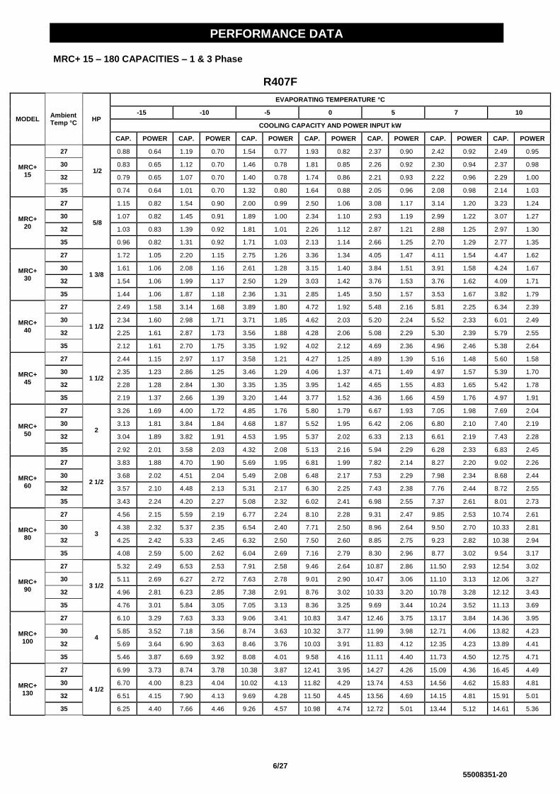
MRC+ 15 – 180 CAPACITIES – 1 & 3 Phase
R407F
MODEL Ambient Temp °C
HP
EVAPORATING TEMPERATURE °C
-15 -10 -5 0 5 7 10
COOLING CAPACITY AND POWER INPUT kW
CAP. POWER CAP. POWER CAP. POWER CAP. POWER CAP. POWER CAP. POWER CAP. POWER
MRC+ 15
27
1/2
0.88 0.64 1.19 0.70 1.54 0.77 1.93 0.82 2.37 0.90 2.42 0.92 2.49 0.95
30 0.83 0.65 1.12 0.70 1.46 0.78 1.81 0.85 2.26 0.92 2.30 0.94 2.37 0.98
32 0.79 0.65 1.07 0.70 1.40 0.78 1.74 0.86 2.21 0.93 2.22 0.96 2.29 1.00
35 0.74 0.64 1.01 0.70 1.32 0.80 1.64 0.88 2.05 0.96 2.08 0.98 2.14 1.03
MRC+ 20
27
5/8
1.15 0.82 1.54 0.90 2.00 0.99 2.50 1.06 3.08 1.17 3.14 1.20 3.23 1.24
30 1.07 0.82 1.45 0.91 1.89 1.00 2.34 1.10 2.93 1.19 2.99 1.22 3.07 1.27
32 1.03 0.83 1.39 0.92 1.81 1.01 2.26 1.12 2.87 1.21 2.88 1.25 2.97 1.30
35 0.96 0.82 1.31 0.92 1.71 1.03 2.13 1.14 2.66 1.25 2.70 1.29 2.77 1.35
MRC+ 30
27
1 3/8
1.72 1.05 2.20 1.15 2.75 1.26 3.36 1.34 4.05 1.47 4.11 1.54 4.47 1.62
30 1.61 1.06 2.08 1.16 2.61 1.28 3.15 1.40 3.84 1.51 3.91 1.58 4.24 1.67
32 1.54 1.06 1.99 1.17 2.50 1.29 3.03 1.42 3.76 1.53 3.76 1.62 4.09 1.71
35 1.44 1.06 1.87 1.18 2.36 1.31 2.85 1.45 3.50 1.57 3.53 1.67 3.82 1.79
MRC+ 40
27
1 1/2
2.49 1.58 3.14 1.68 3.89 1.80 4.72 1.92 5.48 2.16 5.81 2.25 6.34 2.39
30 2.34 1.60 2.98 1.71 3.71 1.85 4.62 2.03 5.20 2.24 5.52 2.33 6.01 2.49
32 2.25 1.61 2.87 1.73 3.56 1.88 4.28 2.06 5.08 2.29 5.30 2.39 5.79 2.55
35 2.12 1.61 2.70 1.75 3.35 1.92 4.02 2.12 4.69 2.36 4.96 2.46 5.38 2.64
MRC+ 45
27
1 1/2
2.44 1.15 2.97 1.17 3.58 1.21 4.27 1.25 4.89 1.39 5.16 1.48 5.60 1.58
30 2.35 1.23 2.86 1.25 3.46 1.29 4.06 1.37 4.71 1.49 4.97 1.57 5.39 1.70
32 2.28 1.28 2.84 1.30 3.35 1.35 3.95 1.42 4.65 1.55 4.83 1.65 5.42 1.78
35 2.19 1.37 2.66 1.39 3.20 1.44 3.77 1.52 4.36 1.66 4.59 1.76 4.97 1.91
MRC+ 50
27
2
3.26 1.69 4.00 1.72 4.85 1.76 5.80 1.79 6.67 1.93 7.05 1.98 7.69 2.04
30 3.13 1.81 3.84 1.84 4.68 1.87 5.52 1.95 6.42 2.06 6.80 2.10 7.40 2.19
32 3.04 1.89 3.82 1.91 4.53 1.95 5.37 2.02 6.33 2.13 6.61 2.19 7.43 2.28
35 2.92 2.01 3.58 2.03 4.32 2.08 5.13 2.16 5.94 2.29 6.28 2.33 6.83 2.45
MRC+ 60
27
2 1/2
3.83 1.88 4.70 1.90 5.69 1.95 6.81 1.99 7.82 2.14 8.27 2.20 9.02 2.26
30 3.68 2.02 4.51 2.04 5.49 2.08 6.48 2.17 7.53 2.29 7.98 2.34 8.68 2.44
32 3.57 2.10 4.48 2.13 5.31 2.17 6.30 2.25 7.43 2.38 7.76 2.44 8.72 2.55
35 3.43 2.24 4.20 2.27 5.08 2.32 6.02 2.41 6.98 2.55 7.37 2.61 8.01 2.73
MRC+ 80
27
3
4.56 2.15 5.59 2.19 6.77 2.24 8.10 2.28 9.31 2.47 9.85 2.53 10.74 2.61
30 4.38 2.32 5.37 2.35 6.54 2.40 7.71 2.50 8.96 2.64 9.50 2.70 10.33 2.81
32 4.25 2.42 5.33 2.45 6.32 2.50 7.50 2.60 8.85 2.75 9.23 2.82 10.38 2.94
35 4.08 2.59 5.00 2.62 6.04 2.69 7.16 2.79 8.30 2.96 8.77 3.02 9.54 3.17
MRC+ 90
27
3 1/2
5.32 2.49 6.53 2.53 7.91 2.58 9.46 2.64 10.87 2.86 11.50 2.93 12.54 3.02
30 5.11 2.69 6.27 2.72 7.63 2.78 9.01 2.90 10.47 3.06 11.10 3.13 12.06 3.27
32 4.96 2.81 6.23 2.85 7.38 2.91 8.76 3.02 10.33 3.20 10.78 3.28 12.12 3.43
35 4.76 3.01 5.84 3.05 7.05 3.13 8.36 3.25 9.69 3.44 10.24 3.52 11.13 3.69
MRC+ 100
27
4
6.10 3.29 7.63 3.33 9.06 3.41 10.83 3.47 12.46 3.75 13.17 3.84 14.36 3.95
30 5.85 3.52 7.18 3.56 8.74 3.63 10.32 3.77 11.99 3.98 12.71 4.06 13.82 4.23
32 5.69 3.64 6.90 3.63 8.46 3.76 10.03 3.91 11.83 4.12 12.35 4.23 13.89 4.41
35 5.46 3.87 6.69 3.92 8.08 4.01 9.58 4.16 11.11 4.40 11.73 4.50 12.75 4.71
MRC+ 130
27
4 1/2
6.99 3.73 8.74 3.78 10.38 3.87 12.41 3.95 14.27 4.26 15.09 4.36 16.45 4.49
30 6.70 4.00 8.23 4.04 10.02 4.13 11.82 4.29 13.74 4.53 14.56 4.62 15.83 4.81
32 6.51 4.15 7.90 4.13 9.69 4.28 11.50 4.45 13.56 4.69 14.15 4.81 15.91 5.01
35 6.25 4.40 7.66 4.46 9.26 4.57 10.98 4.74 12.72 5.01 13.44 5.12 14.61 5.36
PERFORMANCE DATA

7/27 55008351-20
MODEL Ambient Temp °C
HP
EVAPORATING TEMPERATURE °C
-15 -10 -5 0 5 7 10
COOLING CAPACITY AND POWER INPUT kW
CAP. POWER CAP. POWER CAP. POWER CAP. POWER CAP. POWER CAP. POWER CAP. POWER
MRC+ 150
27
5
7.62 3.78 9.53 3.83 11.32 3.92 13.54 4.00 15.57 4.31 16.46 4.41 17.95 4.55
30 7.31 4.05 8.98 4.09 10.93 4.18 12.89 4.34 14.98 4.58 15.88 4.68 17.27 4.87
32 7.10 4.20 8.62 4.18 10.57 4.34 12.54 4.50 14.79 4.75 15.43 4.88 17.35 5.08
35 6.82 4.46 8.35 4.52 10.10 4.63 11.97 4.80 13.88 5.08 14.66 5.19 15.94 5.43
MRC+ 165
27
6
9.09 4.41 11.37 4.47 13.50 4.57 16.15 4.66 18.57 5.03 19.64 5.15 21.41 5.31
30 8.72 4.73 10.71 4.78 13.03 4.88 15.38 5.07 17.87 5.36 18.95 5.47 20.60 5.70
32 8.48 4.91 10.28 4.89 12.61 5.07 14.96 5.26 17.64 5.56 18.41 5.70 20.70 5.94
35 8.13 5.22 9.97 5.29 12.05 5.41 14.28 5.62 16.55 5.95 17.49 6.08 19.01 6.37
MRC+ 180
27
7 1/2
10.05 4.84 12.57 4.91 14.92 5.03 17.85 5.12 20.53 5.53 21.71 5.66 23.66 5.84
30 9.64 5.20 11.83 5.26 14.41 5.37 17.00 5.58 19.75 5.89 20.94 6.01 22.77 6.27
32 9.37 5.40 11.36 5.37 13.93 5.58 16.53 5.79 19.50 6.12 20.35 6.28 22.88 6.54
35 8.99 5.74 11.02 5.82 13.31 5.96 15.79 6.19 18.30 6.55 19.33 6.69 21.01 7.01

8/27 55008351-20
MRC+ 15 – 180 CAPACITIES – 1 & 3 Phase
R404A
MODEL Ambient Temp °C
HP
EVAPORATING TEMPERATURE °C
-15 -10 -5 0 5 7 10
COOLING CAPACITY AND POWER INPUT kW
CAP. POWER CAP. POWER CAP. POWER CAP. POWER CAP. POWER CAP. POWER CAP. POWER
MRC+ 15
27
1/2
0.95 0.66 1.23 0.73 1.54 0.79 1.86 0.84 2.26 0.90 2.28 0.91 2.32 0.93
30 0.88 0.66 1.15 0.73 1.45 0.79 1.75 0.86 2.13 0.91 2.15 0.93 2.18 0.95
32 0.84 0.66 1.10 0.73 1.38 0.80 1.67 0.86 2.04 0.92 2.06 0.94 2.08 0.97
35 0.79 0.66 1.03 0.73 1.30 0.81 1.57 0.88 1.91 0.94 1.92 0.96 1.94 1.00
MRC+ 20
27
5/8
1.23 0.85 1.59 0.93 2.00 1.01 2.41 1.10 2.93 1.17 2.96 1.19 3.01 1.22
30 1.15 0.85 1.49 0.94 1.88 1.02 2.27 1.11 2.76 1.19 2.79 1.21 2.82 1.24
32 1.09 0.85 1.43 0.94 1.80 1.03 2.17 1.12 2.65 1.20 2.67 1.23 2.70 1.26
35 1.02 0.85 1.33 0.94 1.68 1.04 2.03 1.14 2.48 1.23 2.50 1.26 2.52 1.30
MRC+ 30
27
1 3/8
1.84 1.09 2.28 1.19 2.75 1.29 3.24 1.39 3.85 1.47 3.89 1.53 4.16 1.59
30 1.72 1.09 2.13 1.20 2.59 1.30 3.04 1.41 3.63 1.50 3.65 1.56 3.90 1.63
32 1.64 1.09 2.04 1.20 2.48 1.31 2.91 1.42 3.48 1.52 3.49 1.59 3.73 1.66
35 1.53 1.09 1.91 1.21 2.32 1.33 2.73 1.45 3.25 1.55 3.26 1.63 3.48 1.72
MRC+ 40
27
1 1/2
2.66 1.64 3.24 1.74 3.89 1.85 4.56 1.99 5.22 2.16 5.49 2.23 5.91 2.35
30 2.51 1.65 3.06 1.76 3.67 1.89 4.47 2.04 4.90 2.22 5.15 2.30 5.53 2.42
32 2.40 1.66 2.94 1.77 3.52 1.91 4.11 2.07 4.69 2.26 4.92 2.34 5.28 2.47
35 2.25 1.66 2.75 1.80 3.30 1.95 3.84 2.12 4.36 2.32 4.58 2.41 4.89 2.54
MRC+ 45
27
1 1/2
2.61 1.19 3.07 1.21 3.58 1.24 4.12 1.29 4.66 1.39 4.87 1.47 5.22 1.56
30 2.51 1.27 2.93 1.28 3.43 1.32 3.93 1.37 4.44 1.48 4.64 1.55 4.96 1.66
32 2.43 1.32 2.91 1.33 3.31 1.37 3.80 1.43 4.29 1.53 4.48 1.62 4.94 1.73
35 2.32 1.41 2.71 1.43 3.15 1.46 3.60 1.52 4.06 1.63 4.24 1.72 4.53 1.84
MRC+ 50
27
2
3.49 1.76 4.13 1.78 4.85 1.80 5.59 1.85 6.35 1.93 6.66 1.96 7.16 2.00
30 3.35 1.87 3.95 1.89 4.63 1.91 5.34 1.96 6.05 2.04 6.35 2.07 6.81 2.13
32 3.24 1.94 3.91 1.96 4.48 1.98 5.16 2.03 5.85 2.11 6.13 2.15 6.78 2.21
35 3.09 2.07 3.64 2.09 4.26 2.11 4.90 2.16 5.53 2.25 5.80 2.28 6.21 2.35
MRC+ 60
27
2 1/2
4.10 1.95 4.85 1.97 5.69 2.00 6.56 2.05 7.45 2.14 7.82 2.18 8.41 2.22
30 3.93 2.08 4.64 2.10 5.44 2.12 6.26 2.18 7.10 2.27 7.45 2.31 7.99 2.37
32 3.81 2.16 4.59 2.18 5.26 2.21 6.06 2.26 6.86 2.35 7.20 2.40 7.95 2.47
35 3.63 2.31 4.28 2.33 4.99 2.36 5.75 2.41 6.49 2.51 6.80 2.55 7.29 2.63
MRC+ 80
27
3
4.88 2.24 5.77 2.27 6.77 2.29 7.81 2.36 8.87 2.47 9.31 2.51 10.01 2.56
30 4.68 2.39 5.52 2.42 6.47 2.45 7.46 2.51 8.45 2.62 8.87 2.66 9.51 2.74
32 4.53 2.49 5.46 2.52 6.26 2.55 7.21 2.61 8.17 2.72 8.57 2.77 9.47 2.85
35 4.32 2.67 5.09 2.70 5.95 2.72 6.84 2.79 7.73 2.91 8.10 2.95 8.68 3.04
MRC+ 90
27
3 1/2
5.69 2.59 6.74 2.62 7.91 2.65 9.12 2.73 10.35 2.86 10.87 2.90 11.68 2.96
30 5.46 2.77 6.44 2.80 7.56 2.84 8.71 2.91 9.87 3.04 10.35 3.09 11.10 3.18
32 5.29 2.89 6.38 2.92 7.31 2.96 8.42 3.03 9.54 3.16 10.00 3.22 11.05 3.32
35 5.04 3.11 5.94 3.14 6.94 3.17 7.99 3.25 9.02 3.39 9.45 3.44 10.14 3.54
MRC+ 100
27
4
6.52 3.43 7.88 3.46 9.06 3.50 10.45 3.60 11.86 3.75 12.45 3.81 13.39 3.88
30 6.25 3.63 7.38 3.67 8.66 3.70 9.97 3.80 11.31 3.95 11.86 4.01 12.72 4.12
32 6.06 3.75 7.06 3.73 8.37 3.83 9.65 3.92 10.93 4.08 11.46 4.15 12.66 4.26
35 5.78 3.99 6.81 4.03 7.95 4.07 9.15 4.16 10.33 4.33 10.83 4.39 11.61 4.52
MRC+ 130
27
4 1/2
7.47 3.89 9.03 3.92 10.38 3.97 11.97 4.08 13.59 4.26 14.26 4.32 15.34 4.41
30 7.17 4.12 8.45 4.16 9.92 4.21 11.42 4.32 12.95 4.49 13.59 4.55 14.57 4.68
32 6.95 4.27 8.09 4.24 9.59 4.35 11.05 4.46 12.52 4.64 13.13 4.72 14.50 4.85
35 6.62 4.55 7.80 4.59 9.11 4.63 10.49 4.74 11.84 4.94 12.41 5.00 13.30 5.15
PERFORMANCE DATA
9/27 55008351-20
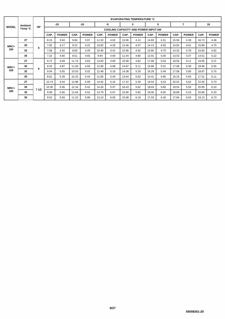
MODEL Ambient Temp °C
HP
EVAPORATING TEMPERATURE °C
-15 -10 -5 0 5 7 10
COOLING CAPACITY AND POWER INPUT kW
CAP. POWER CAP. POWER CAP. POWER CAP. POWER CAP. POWER CAP. POWER CAP. POWER
MRC+ 150
27
5
8.15 3.94 9.84 3.97 11.32 4.02 13.06 4.13 14.82 4.31 15.56 4.38 16.73 4.46
30 7.82 4.17 9.22 4.22 10.82 4.26 12.46 4.37 14.13 4.55 14.82 4.61 15.89 4.75
32 7.58 4.32 8.83 4.29 10.46 4.41 12.06 4.52 13.65 4.70 14.32 4.78 15.82 4.92
35 7.22 4.60 8.51 4.65 9.94 4.69 11.44 4.80 12.91 5.00 13.53 5.07 14.51 5.22
MRC+ 165
27
6
9.72 4.59 11.74 4.63 13.50 4.69 15.58 4.82 17.68 5.03 18.56 5.11 19.95 5.21
30 9.32 4.87 11.00 4.93 12.90 4.98 14.87 5.11 16.86 5.31 17.68 5.39 18.96 5.55
32 9.04 5.05 10.53 5.02 12.48 5.16 14.38 5.29 16.29 5.49 17.08 5.60 18.87 5.75
35 8.61 5.39 10.15 5.44 11.85 5.49 13.64 5.62 15.41 5.85 16.15 5.93 17.31 6.11
MRC+ 180
27
7 1/2
10.74 5.04 12.98 5.09 14.92 5.16 17.22 5.30 19.54 5.53 20.52 5.62 22.05 5.73
30 10.30 5.36 12.16 5.42 14.26 5.47 16.43 5.62 18.63 5.85 19.54 5.93 20.95 6.10
32 9.99 5.56 11.64 5.52 13.79 5.67 15.90 5.82 18.00 6.05 18.88 6.16 20.86 6.33
35 9.52 5.93 11.22 5.99 13.10 6.05 15.08 6.19 17.03 6.45 17.84 6.53 19.13 6.73

10/27 55008351-20
MOUNTING MRC+ These units are designed to stand on a flat surface. If the unit is to be wall mounted the following kits are available.
KIT MRC+ 15-80 MRC+ 90-180
Mounting Bracket 55021100 55021101
Whether floor or wall mounted, it is essential that the mounting surface is capable of supporting the unit weight. Leave space around the unit for air circulation and access for installation and maintenance.
Dimensions in mm.
DIMENSIONS & WEIGHTS MRC+ MRC+ 15-100 (Dimensions in mm.)
MODEL A B C D E F G H Weight (kg)
1 Ph 3 Ph
MRC+ 15 900 300 560 525 185 60 295 275 46 -
MRC+ 20 900 300 560 525 185 60 295 275 47 -
MRC+ 30 900 300 560 525 185 60 295 275 48 48
MRC+ 40 900 300 560 525 185 60 295 275 53 53
MRC+ 45 1000 350 660 495 250 60 345 325 61 -
MRC+ 50 1000 350 660 495 250 60 345 325 64 64
MRC+ 60 1000 350 660 495 250 60 345 325 65 65
MRC+ 80 1000 350 660 495 250 60 345 325 66 66
MRC+ 90 1000 350 760 495 250 70 345 325 76 76
MRC+ 100 1000 350 760 495 250 70 345 325 81 81
1500 min air off
100 min 100 min
600 min
MOUNTING HOLES

11/27 55008351-20
MRC+ 130 – 180 (Dimensions in mm.)
PIPEWORK
Supplied male flare connections (sizes in inches) Model MRC+ 15-180
Size 15 20 30 40 45 50 60 80 90 100 130 150 165 180
Liquid 3/8 3/8 3/8 3/8 3/8 3/8 3/8 1/2 1/2 1/2 1/2 1/2 1/2 1/2
Suction 3/8 1/2 1/2 1/2 1/2 1/2 5/8 5/8 5/8 3/4 3/4 3/4 3/4 7/8*
* Brazed connections MAXIMUM PIPE RUNS
45m maximum including 6m lift (20m MRC+ 15-20). There will be no significant loss of capacity for extended pipe runs provided pipes are correctly sized. CALCULATING EQUIVALENT LENGTHS The effects of bends and fittings must be taken into account. Pipe sizes are based on: Minimum of 2.5 m/s (500 fpm) suction gas velocity for horizontal or downflow. Minimum of 5.0 m/s (1000 fpm) suction gas velocity for upflow. Maximum of 20.0 m/s (4000 fpm) suction gas. Where vertical risers exceed 3m, oil traps must be formed in the pipe. This will help ensure that oil returns to the compressor. Typically fit an oil trap every 3m with a trap at the bottom of the riser.
GOOD PRACTICE Keep pipe runs as short as possible. Avoid sharp bends Fully insulate both suction and liquid including mechanical connections Try to avoid running pipes through hot areas.
MODEL A B C D E Weight (kg)
MRC+ 130 1000 1020 495 251 100 101
MRC+ 150 1000 1020 495 251 100 103
MRC+ 165 1000 1020 495 251 100 103
MRC+ 180 1100 1215 675 211 95 118
B6
0
A 10
C D E
MOUNTING HOLES
417
397
425
12/27 55008351-20
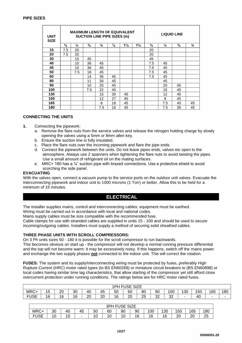
PIPE SIZES
UNIT SIZE
MAXIMUM LENGTH OF EQUIVALENT SUCTION LINE PIPE SIZES (m)
LIQUID LINE
⅜ ½ ⅝ ¾ ⅞ 1⅛ 1⅜ ⅜ ½ ⅝ ¾
15 7.5 20 20
20 7.5 20 20
30 15 45 45
40 10 36 45 7.5 45
45 10 36 45 7.5 45
50 7.5 18 45 7.5 45
60 14 36 45 7.5 45
80 11 30 45 45
90 10 25 45 20 45
100 7.5 22 45 15 45
130 15 30 45 12 45
150 12 27 45 8 45
165 8 18 45 7.5 40 45
180 7.5 16 45 7.5 35 45
CONNECTING THE UNITS 1. Connecting the pipework:
a. Remove the flare nuts from the service valves and release the nitrogen holding charge by slowly opening the valves using a 5mm or 8mm allen key.
b. Ensure the suction line is fully insulated. c. Place the flare nuts over the incoming pipework and flare the pipe ends. d. Connect the pipework between the units. Do not leave pipes ends, valves etc open to the
atmosphere. Always use 2 spanners when tightening the flare nuts to avoid twisting the pipes. Use a small amount of refrigerant oil on the mating surfaces.
e. MRC+ 180 has a ⅞¨ suction pipe with brazed connections. Use a protective shield to avoid scorching the side panel.
EVACUATING With the valves open, connect a vacuum pump to the service ports on the outdoor unit valves. Evacuate the interconnecting pipework and indoor unit to 1000 microns (1 Torr) or better. Allow this to be held for a minimum of 15 minutes.
ELECTRICAL The installer supplies mains, control and interconnecting cables: equipment must be earthed. Wiring must be carried out in accordance with local and national codes. Mains supply cables must be size compatible with the recommended fuse. Cable clamps for use with stranded cables are supplied in units 15 - 100 and should be used to secure incoming/outgoing cables. Installers must supply a method of securing solid sheathed cables. THREE PHASE UNITS WITH SCROLL COMPRESSORS: On 3 Ph units sizes 50 - 180 it is possible for the scroll compressor to run backwards. This becomes obvious on start up - the compressor will not develop a normal running pressure differential and the top will not become warm: it may be excessively noisy. If this happens, switch off the mains power and exchange the two supply phases not connected to the indoor unit. This will correct the rotation. FUSES: The system and its supply/interconnecting wiring must be protected by fuses, preferably High Rupture Current (HRC) motor rated types (to BS EN60269) or miniature circuit breakers to (BS EN60898) or local codes having similar time lag characteristics, that allow starting of the compressor yet still afford close overcurrent protection under running conditions. The ratings below are for HRC motor rated fuses.
1PH FUSE SIZE
MRC+ 15 20 30 40 45 50 60 80 90 100 130 150 165 180
FUSE 16 16 16 20 20 16 20 25 32 32 - 40 - -
3PH FUSE SIZE
MRC+ 30 40 45 50 60 80 90 100 130 150 165 180
FUSE 10 10 - 10 10 10 16 16 16 20 20 25

13/27 55008351-20
The ratings are for the outdoor unit only. Currents for the indoor units including heaters if applicable should be noted and the fuse size increased pro-rata. CONNECTION OF MAINS SUPPLY:
1. Ensure the isolator switch is in the OFF position. 2. Remove front panel. (3screws) 3. Isolator body is located on the inside of the right hand panel. 4. To remove the isolator body from the external switch slide the red lever downwards. 5. Release the main body and lower to the bottom of the unit near the valve panel. 6. Remove lower white plastic cover from the isolator body. 7. Remove knockout hole on the valve panel for your incoming mains supply cable.
14/27 55008351-20
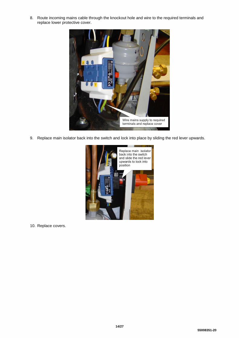
8. Route incoming mains cable through the knockout hole and wire to the required terminals and replace lower protective cover.
9. Replace main isolator back into the switch and lock into place by sliding the red lever upwards.
10. Replace covers.

15/27 55008351-20
R404A REFRIGERANT Charging the System: 1. Evacuate the system and interconnecting pipework as page 8 ensuring the service valves are fully
open. 2. Allow the evacuated system to draw in the majority of the refrigerant charge. 3. The final charge should be adjusted with the system running.
4. All units are fitted with head pressure control. The link wire across the orange terminals allows the fan
to operate at full speed. THIS SHOULD BE REMOVED AFTER CHARGING 5. A random start delay of up to 1 minute occurs when mains is first applied. A 3 minute delay occurs
between successive compressor operations on all systems. 6. Refrigerant and polyolester oil should be introduced through the Schrader valve the service port on the
suction service valve on the outdoor unit. Ensure the refrigerant is the correct type, as shown on the rating plate. R404A must always be added in the liquid state.
7. Run the system for a few minutes to allow it to stabilize. Where possible, charge to a sweat line on the
evaporator. Typical suction pressures on short lines at UK conditions, with high speed evaporator fan, high speed condenser fan, should be; low temperature system approx 4.4 bar (65 psig).
8. Systems should not be overcharged, to avoid liquid return to the compressor
9. HEAD PRESSURE CONTROL SAGINOMIYA (RGE – ZIN4 – SH)
The head pressure controller is factory set to suit the refrigerant. It may be necessary to adjust this to suit site conditions, to raise or lower the nominal head pressure. a. With the system
switched off, connect a high pressure gauge to the liquid line service valve.
b. Switch on the
system, and run for a few minutes to stabilise.
c. The head pressure should be approximately:
R404A: 210-220 psig (14.5-15.2barg) to achieve this adjust the screw clockwise to increase pressure or anticlockwise to decrease. Each ½ turn will alter the pressure by approx 5 psig (0.5 barg) Min fan speed (0 rpm) and fan cut in pressure 200 psig (13.8 barg) are factory set and not adjustable. NOTE: The condenser fan may stop if the operating pressure drops below 200 psig (13.8 barg)
10. HEAD PRESSURE CONTROL ALCO (FSY-42S) & SAGINOMIYA (XGE-4C) The head pressure controller is factory set to suit the refrigerant. It may be necessary to adjust this to suit site conditions, to raise or lower the nominal head pressure. ALCO (FSY-42S) a. With the system switched off, connect a high pressure gauge to the liquid line service valve. b. Switch on the system, and run for a few minutes to stabilise.
c. The head pressure should be approximately:
Electricsbox
Headpressureadjustmentscrew
Fancapacitor
16/27 55008351-20
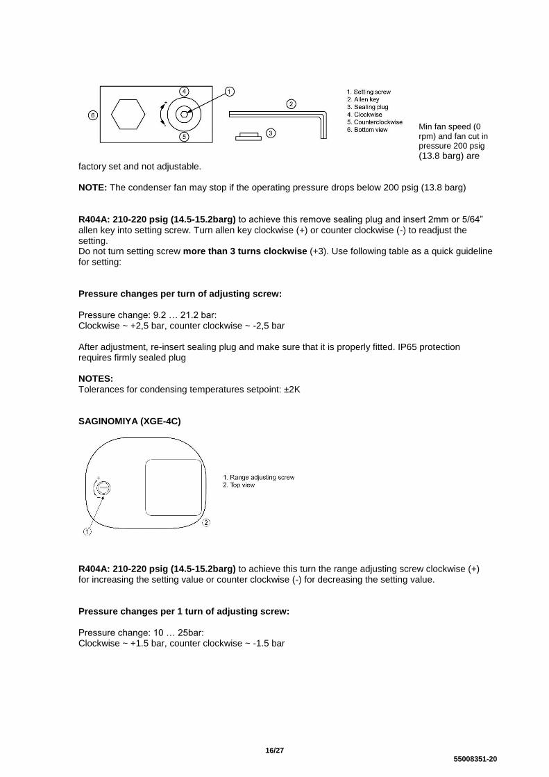
Min fan speed (0 rpm) and fan cut in pressure 200 psig
(13.8 barg) are factory set and not adjustable. NOTE: The condenser fan may stop if the operating pressure drops below 200 psig (13.8 barg) R404A: 210-220 psig (14.5-15.2barg) to achieve this remove sealing plug and insert 2mm or 5/64” allen key into setting screw. Turn allen key clockwise (+) or counter clockwise (-) to readjust the setting. Do not turn setting screw more than 3 turns clockwise (+3). Use following table as a quick guideline for setting: Pressure changes per turn of adjusting screw: Pressure change: 9.2 … 21.2 bar: Clockwise ~ +2,5 bar, counter clockwise ~ -2,5 bar After adjustment, re-insert sealing plug and make sure that it is properly fitted. IP65 protection requires firmly sealed plug NOTES: Tolerances for condensing temperatures setpoint: ±2K SAGINOMIYA (XGE-4C)
R404A: 210-220 psig (14.5-15.2barg) to achieve this turn the range adjusting screw clockwise (+) for increasing the setting value or counter clockwise (-) for decreasing the setting value. Pressure changes per 1 turn of adjusting screw: Pressure change: 10 … 25bar: Clockwise ~ +1.5 bar, counter clockwise ~ -1.5 bar

17/27 55008351-20
ROTA-LOCKED VALVES FITTED TO RECIEVER
END OF LIFE REQUIRMENTS
Refrigerant must be recovered by a certificated technician before the plant is dismantled. Modern refrigerant recovery machines should be able to remove well over 95% of the refrigerant in an old system. All recovered HFC refrigerants can either be:
a) Sent for destruction by incineration at a licenced waste facility
b) Sent to a specialist plant that can re-process the old refrigerant into a gas with properties identical to virgin refrigerant, to create “reclaimed refrigerant”
c) Given a basic cleaning process, to create “recycled refrigerant”
Given the HFC supply shortage that will be created by the phase down process, it is worth trying to send the old refrigerant for reclamation as it may have a good residual value. If the old refrigerant is too contaminated it cannot be reclaimed and must be sent for destruction. It is important not to mix different gases in the same recovery cylinder – as this would render them unsuitable for reclamation. Reclaimed refrigerant can be used in any refrigeration equipment. Recycled refrigerant must always be used with care as it may be contaminated or of unknown composition. The use of recycled refrigerant with a GWP above 2,500 is restricted to either (a) the organisation owning the plant from which the gas was recovered or (b) the organisation that carried out the recovery.
OUT
IN
A
B C
P2P1
POSITION SPINDLE
A
B
C
FUNCTION
OUT CLOSED
ALL OPEN
P1 CLOSED
Pay attention
- P1, P2: optional gages ports.
- The positions IN - OUT could be inverted according to the
employment of client.
- The spindle must be positioned in the position B when the
valve will be connected to the unit.
18/27 55008351-20
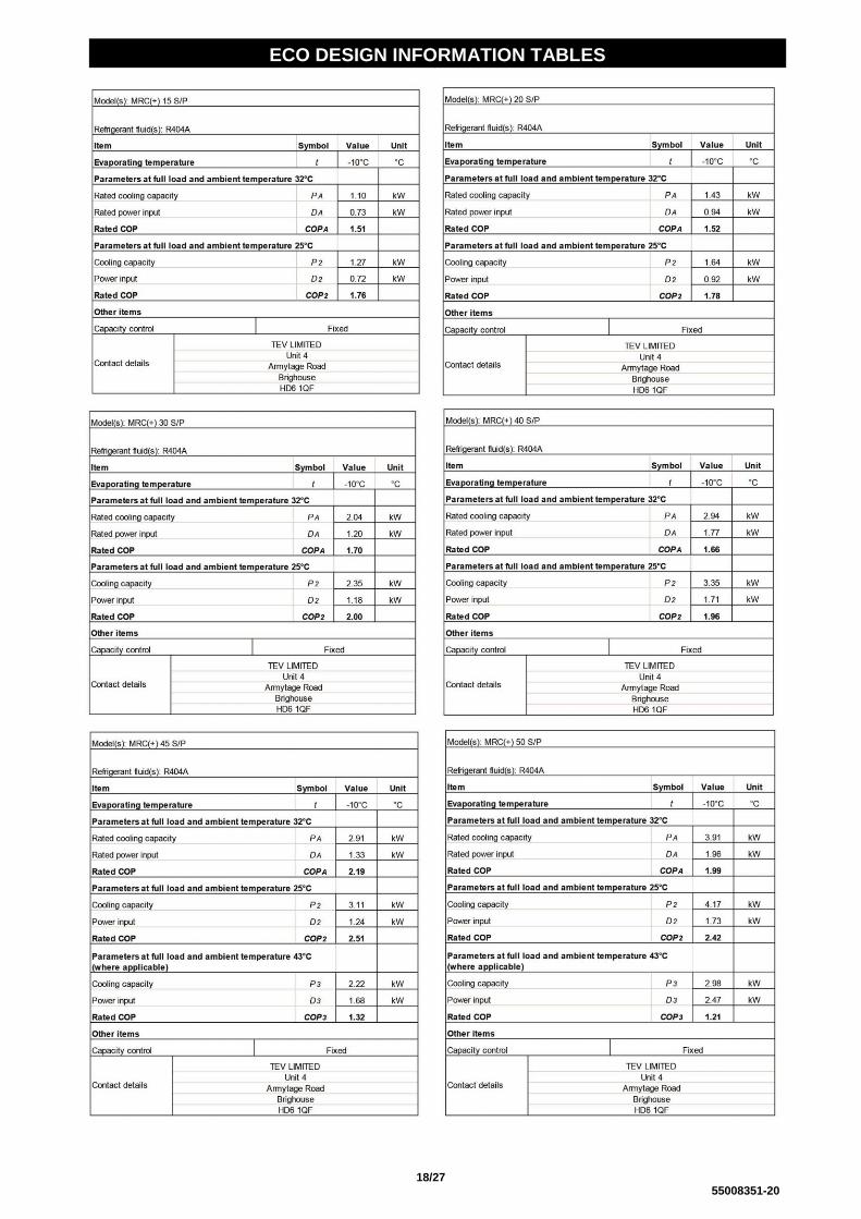
ECO DESIGN INFORMATION TABLES

19/27 55008351-20

20/27 55008351-20

21/27 55008351-20

22/27 55008351-20
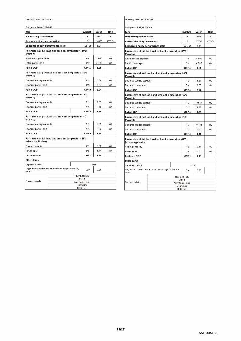
23/27 55008351-20

24/27 55008351-20
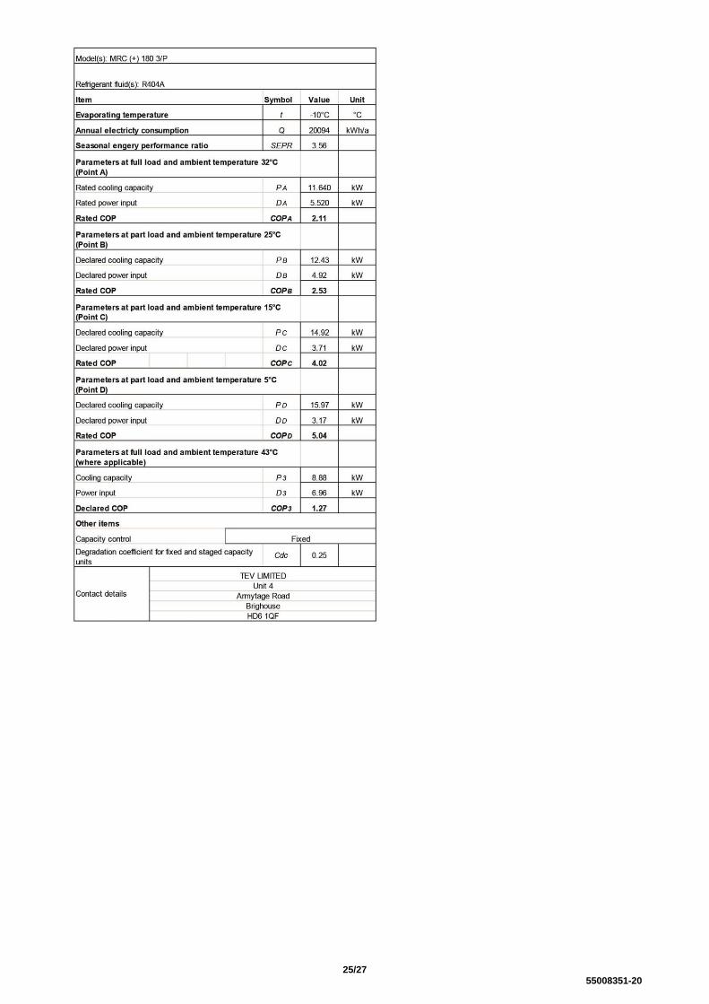
25/27 55008351-20
COMPONENT IDENTIFICATION

26/27 55008351-20
COMPONENT IDENTIFICATION
MRC+ 15 - 100
1 LID 17 COMPRESSOR
2 CONTACTOR 18 HANDLE
3 OVERLOAD 19 FRONT ACCESS
4 HEAT EXCHANGER COIL 20 FAN GUARD
5 REAR ACCESS PANEL 21 FASCIA PANEL
6 MAINS TERMINAL COVER 22 CORNER PANEL
6a ISOLATOR 23 SUPPORT BRACKET
7 FAN CAPACITOR 24 FAN / MOTOR ASSEMBLY
8 BULKHEAD PANEL 25 END CLAMP
9 HP SWITCH (MANUAL, OPTION) 26 TERMINAL
9a DRIER 27 FUSE
10 RECEIVER 28 FUSE TERMINAL
11 SIGHT GLASS 29 TERMINAL (4 WAY)
11a SERVICE VALVE (LIQUID) 30 EARTH TERMINAL
12 SERVICE VALVE (SUCTION) 31 HEAD PRESSURE CONTROL pcb
13 VALVE PANEL 32 3 MINUTE TIMER pcb
14 BASE 33 COMPRESSOR CAPACITOR
15 MOUNTING FOOT 34 ELECTRICS BOX
16 LP SWITCH

27/27 55008351-20
MRC+ 130 – 180
1 LID 17a SERVICE VALVE (LIQUID)
2 FUSE TERMINAL 18 SERVICE VALVE (SUCTION)
3 FUSE 19 VALVE PANEL
4 TERMINAL 20 BASE
5 TERMINAL (4 WAY) 21 MOUNTING FOOT
6 CONTACTOR 22 LP SWITCH
7 EARTH TERMINAL 23 COMPRESSOR
8 END CLAMP 24 HANDLE
9 OVERLOAD 25 FRONT ACCESS PANEL
10 HEAT EXCHANGER COIL 26 FAN GUARD
11 FAN CAPACITOR 27 FASCIA PANEL
12 MAINS TERMINAL COVER 28 CORNER PANEL
13 REAR ACCESS PANEL 29 SUPPORT BRACKET
13a ISOLATOR 30 FAN / MOTOR ASSEMBLY
14 BULKHEAD PANEL 31 HEAD PRESSURE CONTROL pcb
15 HP SWITCH (MANUAL, OPTION) 32 POWER BOARD
15a DRIER 33 3 MINUTE TIMER pcb
16 RECEIVER 34 COMPRESSOR CAPACITOR
17 SIGHT GLASS 35 ELECTRICS BOX