installation & user manual… · installation & user manual ... blades and a third...
TRANSCRIPT

Shaping the future of sound reinforcement
Installation & User Manual
AXYS® CerberusMulti I/O interface(Part No. 391010)
Multi I/O Surveillance Station
Power supply OK
Status external
failure relay
Identification
RS-485 Send
RS-485 Receive
Cerberus
Mains100-240V~20W
RS-485
Input 1
Rese
t
Failu
re R
elay
RS-485 link
Input 2
Outputs
Out1
Out5
Out2
Out6
Out3
Out7
Out4
Out8
CO NC NO
A
B
Inputs
CH1
CH17
CH2
CH18
CH3
CH19
CH4CH5
CH6CH7
CH8CH9
CH10CH11
CH12CH13
CH14CH15
CH16
CH20CH21
CH22CH23
CH24CH25
CH26CH27
CH28CH29
CH30CH31
CH32
MADE BY DURAN AUDIO BV, ZALTBOMMEL, HOLLAND
CO AC AOCO AC AO
CO AC AOCO AC AO
DGY
ZB
A
DGY
ZB
A
+5V
+5V
Analo
g Inp
uts(0
-10V
)
Outpu
ts max
. 200
mA

AXYS® Cerberus rev 1.0
201605/CERB_1.02
REFERENCE TO EC STATEMENT OF CONFORMITY
This document confirms that products manufactured by
Duran Audio bearing the CE label meet all the requirements
in the EMC directive 2004/108/EC and LV directive 2006/95/
EC laid down by the Member States Council for adjustment
of legal requirements. Furthermore the products comply
with the rules and regulations from 30 August 1995
referring to the electromagnetic compatibility of devices.
Duran Audio products bearing the CE label comply with
the following harmonised or national standards:
EMC:
EN 55103-1; E1, E2, E3
EN 55103-2; E1, E2, E3
EN 50130-4
EN 50121-4
Safety:
IEC 60065: 2001 (ed7); A1: 2007, A2: 2010
Mains Harmonics:
EN 61000-3-2: 2001
Insulation:
Class1
Duran Audio BV Koxkampseweg 10
5301 KK Zaltbommel
The Netherlands
Tel: +31 418 515583
Fax: +31 418 518077
Zaltbommel, May 2012
USER’S NOTICE AND DISClAIMER
No part of this manual may be reproduced, transmitted,
transcribed, stored in a database system or translated
without the express written permission of Duran Audio BV.
Documentation kept by the end user for back-up purposes
is excluded from the above.
All products and corporate names mentioned in this
manual may be registered trademarks or copyrights
of their respective companies. They are used here for
indicative purposes only.
The information contained in this manual has been carefully
checked for accuracy; however no guarantee is given with
respect to its correctness. Duran Audio BV accepts no
responsibility or liability for any errors or inaccuracies that
may appear in this manual or the products described in it.
Specifications and information contained in this manual
are subject to change at any time without notice.
© 1998-2016 Duran Audio BV. All rights reserved.

AXYS® Cerberus rev 1.0
201605/CERB_1.0 3
TABlE OF CONTENTS
REFERENCE TO EC STATEMENT OF CONFORMITY . . . . . . . . . . . . . . . . . . . . . . .2User’s Notice and disclaimer . . . . . . . . . . . . . . . . . . . . . . . . . . . . . . . . . . . . . . . . . . . . 2
TABlE OF CONTENTS . . . . . . . . . . . . . . . . . . . . . . . . . . . . . . . . . . . . . . . . . . . .3IMPORTANT SAFETY INSTRUCTIONS . . . . . . . . . . . . . . . . . . . . . . . . . . . . . . . . .4INTRODUCTION . . . . . . . . . . . . . . . . . . . . . . . . . . . . . . . . . . . . . . . . . . . . . . . . .5
Overview. . . . . . . . . . . . . . . . . . . . . . . . . . . . . . . . . . . . . . . . . . . . . . . . . . . . . . . . . . . 5Features . . . . . . . . . . . . . . . . . . . . . . . . . . . . . . . . . . . . . . . . . . . . . . . . . . . . . . . . . . . 5What’s in the packaging . . . . . . . . . . . . . . . . . . . . . . . . . . . . . . . . . . . . . . . . . . . . . . . 5
GENERAl DESCRIPTION . . . . . . . . . . . . . . . . . . . . . . . . . . . . . . . . . . . . . . . . . .6Block diagram and system description . . . . . . . . . . . . . . . . . . . . . . . . . . . . . . . . . . . . 6Front Panel . . . . . . . . . . . . . . . . . . . . . . . . . . . . . . . . . . . . . . . . . . . . . . . . . . . . . . . . . 8Rear Panel . . . . . . . . . . . . . . . . . . . . . . . . . . . . . . . . . . . . . . . . . . . . . . . . . . . . . . . . . . 9
INSTAllATION AND OPERATION . . . . . . . . . . . . . . . . . . . . . . . . . . . . . . . . . . .10Mechanical Installation . . . . . . . . . . . . . . . . . . . . . . . . . . . . . . . . . . . . . . . . . . . . . . . 10
Ventilation. . . . . . . . . . . . . . . . . . . . . . . . . . . . . . . . . . . . . . . . . . . . . . . . . . . 10Connector and Wiring details . . . . . . . . . . . . . . . . . . . . . . . . . . . . . . . . . . . . . . . . . . 10
AC Mains. . . . . . . . . . . . . . . . . . . . . . . . . . . . . . . . . . . . . . . . . . . . . . . . . . . . 10Digital Inputs. . . . . . . . . . . . . . . . . . . . . . . . . . . . . . . . . . . . . . . . . . . . . . . . . 11Analogue inputs . . . . . . . . . . . . . . . . . . . . . . . . . . . . . . . . . . . . . . . . . . . . . . 13Relay outputs . . . . . . . . . . . . . . . . . . . . . . . . . . . . . . . . . . . . . . . . . . . . . . . . 14Control connections . . . . . . . . . . . . . . . . . . . . . . . . . . . . . . . . . . . . . . . . . . . 14
Status LEDs . . . . . . . . . . . . . . . . . . . . . . . . . . . . . . . . . . . . . . . . . . . . . . . . . . . . . . . . 16
CONFIGURING CERBERUS wITH wINCONTROl . . . . . . . . . . . . . . . . . . . . . . .17Unit Status . . . . . . . . . . . . . . . . . . . . . . . . . . . . . . . . . . . . . . . . . . . . . . . . . . . . . . . . 17Digital Inputs. . . . . . . . . . . . . . . . . . . . . . . . . . . . . . . . . . . . . . . . . . . . . . . . . . . . . . . 17Analogue inputs . . . . . . . . . . . . . . . . . . . . . . . . . . . . . . . . . . . . . . . . . . . . . . . . . . . . 18Outputs . . . . . . . . . . . . . . . . . . . . . . . . . . . . . . . . . . . . . . . . . . . . . . . . . . . . . . . . . . . 18Surveillance functions . . . . . . . . . . . . . . . . . . . . . . . . . . . . . . . . . . . . . . . . . . . . . . . . 18
APPENDIx . . . . . . . . . . . . . . . . . . . . . . . . . . . . . . . . . . . . . . . . . . . . . . . . . . . .19Technical Specifications. . . . . . . . . . . . . . . . . . . . . . . . . . . . . . . . . . . . . . . . . . . . . . . 19Maintenance and Warranty Information . . . . . . . . . . . . . . . . . . . . . . . . . . . . . . . . . . 19Software and Firmware updates . . . . . . . . . . . . . . . . . . . . . . . . . . . . . . . . . . . . . . . . 19Network Cables. . . . . . . . . . . . . . . . . . . . . . . . . . . . . . . . . . . . . . . . . . . . . . . . . . . . . 19

AXYS® Cerberus rev 1.0
201605/CERB_1.04
IMPORTANT SAFETY INSTRUCTIONS
This symbol is intended to alert you to the
presenceof uninsulated dangerous voltages
within the product’s enclosure that may be of sufficient
magnitude to constitute a risk of electric shock.
This symbol is used throughout this manual and
is intended to alert you to the presence of
important instructions.
1. Read these instructions.
2. Keep these instructions.
3. Heed all warnings.
4. Follow all instructions.
5. Do not use this apparatus near water.
6. Clean only with dry cloth.
7. Do not block any ventilation openings. Install in
accordance with the manufacturer’s instructions.
8. Do not install near any heat sources such as radiators,
heat registers, stoves, or other apparatus (including
amplifiers) that produce heat.
9. Do not defeat the safety purpose of the polarised or
grounding-type plug. A grounding type plug has two
blades and a third grounding prong. The wide blade
or the third prong is provided for your safety. If the
provided plug does not fit into your outlet, consult
an electrician for replacement of the obsolete outlet.
10. Protect the power cord from being walked on or
pinched particularly at plugs, convenience receptacles,
and the point where they exit from the apparatus.
11. Only use attachments/accessories specified by the
manufacturer.
12. Unplug this apparatus during lightning storms or
when unused for long periods of time.
13. Refer servicing to qualified service personnel.
Servicing is required when the apparatus has been
damaged in any way, such as the power-supply cord
or plug being damaged, liquid has been spilled or
objects have fallen into the apparatus, the apparatus
has been exposed to rain or moisture, does not
operate normally, or has been dropped.
warning - To reduce the risk of fire or electric
shock, do not expose this apparatus to rain or
moisture and objects filled with liquids, such as vases,
should not be placed on this apparatus.
warning - To disconnect this apparatus from the
mains power supply, turn off the power at the red
rocker switch at the extreme left of the front panel and
remove the connector from the mains input socket labelled
Mains on the rear panel.
warning - This apparatus is a Class I device and
must be connected to a mains socket outlet that
provides a safety ground connection.

AXYS® Cerberus rev 1.0
201605/CERB_1.0 5
Thank you for purchasing this AXYS® Cerberus unit.
In order to get the best out of your Cerberus, please take
the time to read through this manual before you install
and use it for the first time.
OVERVIEw
The AXYS Cerberus has been designed to act as a
surveillance hub for the various components making up a
life-safety or other critical audio system. Cerberus supports
a wide variety of products – from Duran Audio or other
manufacturers, and will continuously monitor and report
the operational status of all equipment connected to it.
System components of all types – for example, digital
audio processing units, UPS’s or emergency sound stores
- which are provided with a “fault” tally or “watchdog”
output of some kind, can be connected. This allows full
surveillance of all audio system components from a remote
location, and, if the audio system has been appropriately
configured, can automatically bring secondary backup
components on-line when pre-defined failure events occur.
Cerberus may be programmed with AXYS’s WinControl
software by the installer to recognise fault conditions in
connected equipment via 32 digital and 2 analogue inputs,
and to report faults in a variety of ways, including RS-485
messages and 8 internal volt-free changeover relays.
FEATURES
• 32 programmable digital “logic” inputs
• 2 programmable analogue “logic” inputs
• 8 programmable isolated changeover relays
• Dual-contact surveillance/failure relay, suitable for
volt-free monitoring
• Bi-directional RS-485 interface
• RS-485 breakout connection
• Full configuration, control and monitoring with AXYS
WinControl software
• Universal power supply (100-240 VAC, ±10%)
wHAT’S IN THE PACKAGING
In addition to the Cerberus itself, each unit is shipped with
the following items:
• Installation and User Manual (this document)
• AC power cable (2 m), fitted with an IEC connector
and a European-style mains plug
• Full set of mating screw-terminal connectors
INTRODUCTION

AXYS® Cerberus rev 1.0
201605/CERB_1.06
BlOCK DIAGRAM AND SYSTEM DESCRIPTION
MicroController
Externalfailurerelay
Pull-Up
PSU
In 1
In 2
In 3
In 4
In 5
In 6
In 7
In 8
CH1OUT 1
OUT 2
OUT 3
OUT 4
OUT 5
OUT 6
OUT 7
OUT 8
Digital input 1 to 8
Digital input 9 to 16
Digital input 17 to 24
Digital input 25 to 32
CH2
CH3
CH4
CH5
CH6
CH7
CH8
+ 5V
Front LEDs
Input 1
Input 2
RS-485 & RS-485 link
Sensor supply
Reset switch
Internalsupplies
Mains
fig.1: Block Diagram
GENERAl DESCRIPTION
AXYS® Cerberus rev 1.0
201605/CERB_1.0 7
The simplified block diagram “fig.1: Block Diagram” on
page 6 shows the unit’s internal signal routing.
The unit has 32 digital “logic” inputs, which may be
configured via WinControl (in blocks of 8 inputs) to either
monitor input logic levels (nominally 0 or +5 V), or, with
a pull-up resistor enabled, as impedance-sensing inputs.
Two high-impedance, electronically-balanced inputs for
analogue signals are also provided, which are designed to
monitor DC voltages between 0 and +10 V.
The inputs are constantly analysed by the internal
micro-controller and their states compared with a set of
conditions defined by the user in WinControl. Cerberus may
be programmed to activate any one (or a combination) of
its eight outputs when a defined condition is met at any
of the inputs, or in response to a command via the RS-485
network. For example, an input condition might be a fault
tally or watchdog output on an item of external equipment
going logic high (or low) to indicate a fault state within
the item; alternatively an out-of-range voltage from a
temperature sensor connected to an analogue input might
indicate an extreme of temperature. The eight outputs
are in the form of single-pole changeover relays, with
both Active Closed (AC) and Active Open (AO) contacts
available.
Cerberus also incorporates its own surveillance function,
which activates an externally-accessible two-pole
changeover relay in the event of various definable fault
conditions. These are also configured in WinControl.
In addition to activation of the output and failure relays,
fault reporting is also conducted via the RS-485 serial
port. This allows Cerberus to be included in a network of
AXYS amplifiers, line drivers and loudspeakers, and the
operational state of all equipment connected to it to be
continually monitored at a remote location using an AXYS
WinControl Server.
The power supply is conservatively-rated and operates on
any AC supply voltage from 100 V to 240 V.

AXYS® Cerberus rev 1.0
201605/CERB_1.08
FRONT PANEl
Multi I/O Surveillance Station
Power
supp
ly OK
Status
exter
nal
failur
e rela
yIde
ntific
ation
RS-485 S
end
RS-485 R
eceiv
e
Cerberus
1 2 3 4 5 6
fig.2: Front panel view
REF . PANEl lEGEND ITEM
1 Power switch with internal neon indicator (red)
2 Power supply OK PSU status LED (green)
3 Status external failure relay Bi-colour LED (green/red), indicates failure state
4 Identification Unit identification LED (green)
5 RS-485 Send LED (orange) indicates Cerberus is transmitting RS-485 data to the network
6 RS-485 Receive LED (orange) indicates Cerberus is receiving RS-485 data from the network

AXYS® Cerberus rev 1.0
201605/CERB_1.0 9
REAR PANEl
Mains100-240V~
20W
RS-485 Input 1
Res
et
Failu
re R
elay
RS-485 link Input 2 Outputs
Out1
Out5
Out2
Out6
Out3
Out7
Out4
Out8
CO NC NO
A
B
Inputs
CH1
CH17
CH2
CH18
CH3
CH19
CH4 CH5 CH6 CH7 CH8 CH9 CH10 CH11 CH12 CH13 CH14 CH15 CH16
CH20 CH21 CH22 CH23 CH24 CH25 CH26 CH27 CH28 CH29 CH30 CH31 CH32MADE BY DURAN AUDIO BV, ZALTBOMMEL, HOLLAND
CO AC AO CO AC AO CO AC AO CO AC AODG Y Z B A
DG Y Z B A
+5V
+5V
Anal
og In
puts
(0-1
0V)
Out
puts
max
. 200
mA
7 11 18
12 178
9
10
13
14
15
16
fig.3: Rear panel view
REF . PANEl lEGEND ITEM7 RS-485 RS-485 comms port8 RS-485 link RS-485 breakout for further equipment9 Input 1 Analogue DC voltage input 1 10 Input 2 Analogue DC voltage input 211
Inputs (CH1 – CH32)Digital inputs 1 to 16
12 Digital inputs 17 to 3213 Out 1 to Out 4 Relay outputs 1 to 414 Out 5 to Out 8 Relay outputs 5 to 815 Failure Relay A Failure relay contacts A16 Failure Relay B Failure relay contacts B17 Reset Processor hardware reset button18 Mains IEC mains connector with integral fuse-holder
Wiring details for all the rear connectors can be found in subsequent sections of the manual.

AXYS® Cerberus rev 1.0
201605/CERB_1.010
MECHANICAl INSTAllATION
Cerberus is designed to be mounted in a standard 19”
equipment rack. The front panel is fitted with rackmount
ears for this purpose. Cerberus occupies 1U of vertical rack
space.
VentilationCerberus is cooled by natural convection. The unit should
remain within its operational temperature range under
most circumstances, but if it is to be installed in a location
of high ambient temperature, and/or in a rack containing
a significant quantity of heat-generating equipment
(see below), consideration should be given to climate-
controlling the room in which the equipment rack is
situated.
Installation of a Cerberus unit in a 19” rack
immediately above or below another item of
equipment generating a significant amount of heat (e.g., a
power amplifier) is not recommended. Plain or slotted 1U
blank panels should be used as spacers.
CONNECTOR AND wIRING DETAIlS
AC Mainswarning - This apparatus is a Class I device and
must be connected to a mains socket outlet that
provides a safety ground connection.
warning - The Presence of mains voltage is not
indicated by the front panel Power supply OK
LED. This LED indicates the operational status of the unit
and should not be used as a mains voltage indicator.
v
*Numbers in square brackets refer to the figs on pages 8 & 9
AC power is via a rear panel IEC mains connector
[18]*. An IEC mains cable (power cord) fitted
with a European-style plug is supplied with the unit. If the
standard AC outlets in the territory are of a different type,
an IEC mains lead fitted with the correct style of plug
should be sourced. Alternatively, fit the correct type of
mains plug, carefully observing the following cable colour
codes:
PIN CONNECTCOlOUR
(EUROPE)
COlOUR
(US)
L Live Brown Black
N Neutral Blue White
E Earth (Ground) Green/Yellow Green
The Cerberus incorporates a “universal” PSU, and will
operate on all AC mains voltages from 100 V to 240 V.
The connector assembly has an integral fuse holder. Note
the fuse specifications below:
230 V & 115 V
Type T3.15A (slo-blo)
Size 20 x 5 mm
Rating 3.15 A
In the event of a blown fuse always first
investigate why it blew. Only replace a fuse with
one of the type and rating specified. The fuse holder has
space for storage of a spare fuse. Never attempt to replace
a fuse without first removing the IEC plug from the unit.
INSTAllATION AND OPERATION

AXYS® Cerberus rev 1.0
201605/CERB_1.0 11
Digital InputsConnections to the 32 digital inputs are on 2-pin 3.81 mm-
pitch screw-terminal connectors. Mating connectors are
supplied with the unit.
The inputs are differential, and are designed to operate
on nominal logic levels of 0 and +5 V DC. The maximum
voltage that can be applied at these inputs is ±24 V DC.
fig.4: Digital Input Diagram
Wiring to the digital inputs will depend on the equipment
being connected. Note that the ‘-‘ pin of each input is
referenced to internal ground via a 4.7 kohm resistor.
Connecting to a relay
The ‘+’ and ‘-‘ pins may be connected to an external
relay’s CO/NO or CO/NC volt-free contacts. In this case,
the internal pull-up control will need to be enabled in
WinControl. (Note that the pull-ups are enabled in blocks
of eight inputs).
fig.5: External Relay Connection CO/NC
fig.6: External Relay Connection CO/NO
NOTE: Relays are shown in energised state - i.e., “no-fault”.

AXYS® Cerberus rev 1.0
201605/CERB_1.012
If a changeover relay is available, either NC or NO
contacts may be used, and the logic sense programmed
accordingly. If the relay is only single-contact, establish
from the equipment manual whether it is NO or NC for a
non-fault condition, and use the wiring shown. Note that
impedance-sensing connections, if available, are preferred
for critical applications (see “Connecting to switched-
impedance outputs” on page 13).
Connecting to an open-collector output
Some equipment presents an “open-collector” output.
With this type of output, a transistor is turned on, lowering
its collector voltage to a logic “low” level. The ‘+’ terminal
of the digital input should be returned to the +V rail of
the equipment, which is usually available on an adjacent
terminal. Note that the maximum permissible value of +V
is +24 V.
fig.7: Open-Collector Connection
The pull-up control for a digital input connected to an
open-collector output should be disabled.
Connecting to opto-coupled outputs
If the equipment being monitored uses opto-coupled
outputs, the same principle as above (Connecting to
an open-collector output) should be employed, as the
“switching” part of the opto-coupler is essentially a
transistor. The optical coupling to an LED ensures full
electrical isolation between the item of equipment and
Cerberus.
DIGITALINPUT
EXTERNAL EQUIPMENT
(PULL-UP ENABLED)
+ -
fig.8: Opto-Coupler Connection
The pull-up control for a digital input connected to an
opto-coupled output should be enabled.

AXYS® Cerberus rev 1.0
201605/CERB_1.0 13
Connecting to switched-impedance outputs
Some equipment (including many AXYS products) use
impedance switching to indicate a fault state. Impedance-
sensing has the advantage over simple short/open-circuit
detection in that it can distinguish between unit failure
and cable faults.
fig.9: Impedance-Sensing Connection
The diagram shows a typical arrangement for impedance-
sensed fault indication. The two terminals of the external
equipment may simply be connected to the digital input as
shown. In a no-fault state, the impedance presented to the
digital input is 10 kohms. If a fault condition occurs, the
relay opens, and the impedance rises to 20 kohms.
The pull-up control for a digital input configured for
impedance sensing should be enabled.
Analogue inputsCerberus provides two balanced analogue inputs for
external voltage sensing. (These are referred to as
“Aux inputs” in WinControl.) They may be connected to
any variable DC voltage; possible applications include
temperature sensing, monitoring of back-up battery state
and of external PSU voltage in a relay-controlled redundant
amplifier-switching configuration.
The analogue inputs are on 4-pin 3.81 mm-pitch screw-
terminal connectors. Mating connectors are supplied with
the unit. Two of the four terminals (‘+’ and ‘-‘) constitute
a differential input, and the external voltage being sensed
should be applied across these. Use two-core screened
cable to connect to the external equipment and connect
the screen of the cable to the terminal marked with an
earth (ground) symbol. +5 V is also made available at
the analogue input connector for situations where a DC
voltage is required by a sensor. The DC current which may
be drawn from each of the analogue inputs in this way is
200 mA.
fig.10: Analogue Input Connection
The analogue input is designed to operate in the range
0 to +10 V. Upper and lower thresholds can be set in
WinControl; a fault condition will be registered if the
external analogue voltage is not between the two
thresholds. When configuring the analogue inputs, it is
helpful to open the Properties window (Tools>Status
Properties), open the Input tab and observe the
Aux input properties of the analogue input to
check that the thresholds are being set correctly.
The impedance of the analogue input is 2 Mohms, and
thus will not load the source. The maximum level which
may be applied to the analogue input is ±50 V.
AXYS® Cerberus rev 1.0
201605/CERB_1.014
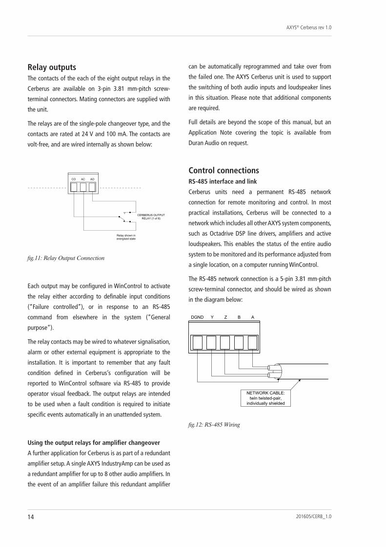
Relay outputsThe contacts of the each of the eight output relays in the
Cerberus are available on 3-pin 3.81 mm-pitch screw-
terminal connectors. Mating connectors are supplied with
the unit.
The relays are of the single-pole changeover type, and the
contacts are rated at 24 V and 100 mA. The contacts are
volt-free, and are wired internally as shown below:
fig.11: Relay Output Connection
Each output may be configured in WinControl to activate
the relay either according to definable input conditions
(“Failure controlled”), or in response to an RS-485
command from elsewhere in the system (“General
purpose”).
The relay contacts may be wired to whatever signalisation,
alarm or other external equipment is appropriate to the
installation. It is important to remember that any fault
condition defined in Cerberus’s configuration will be
reported to WinControl software via RS-485 to provide
operator visual feedback. The output relays are intended
to be used when a fault condition is required to initiate
specific events automatically in an unattended system.
Using the output relays for amplifier changeover
A further application for Cerberus is as part of a redundant
amplifier setup. A single AXYS IndustryAmp can be used as
a redundant amplifier for up to 8 other audio amplifiers. In
the event of an amplifier failure this redundant amplifier
can be automatically reprogrammed and take over from
the failed one. The AXYS Cerberus unit is used to support
the switching of both audio inputs and loudspeaker lines
in this situation. Please note that additional components
are required.
Full details are beyond the scope of this manual, but an
Application Note covering the topic is available from
Duran Audio on request.
Control connectionsRS-485 interface and link
Cerberus units need a permanent RS-485 network
connection for remote monitoring and control. In most
practical installations, Cerberus will be connected to a
network which includes all other AXYS system components,
such as Octadrive DSP line drivers, amplifiers and active
loudspeakers. This enables the status of the entire audio
system to be monitored and its performance adjusted from
a single location, on a computer running WinControl.
The RS-485 network connection is a 5-pin 3.81 mm-pitch
screw-terminal connector, and should be wired as shown
in the diagram below:
fig.12: RS-485 Wiring
AXYS® Cerberus rev 1.0
201605/CERB_1.0 15
Note that 2-pair cable, with each pair individually-screened,
should be used for RS-485 connection. The transmit (Tx)
and receive (Rx) balanced data lines must be wired via
their own twisted pairs. CAT-5 type UTP or FTP cable is
NOT suitable. Please refer to the Appendix section of the
manual for cable specifications.
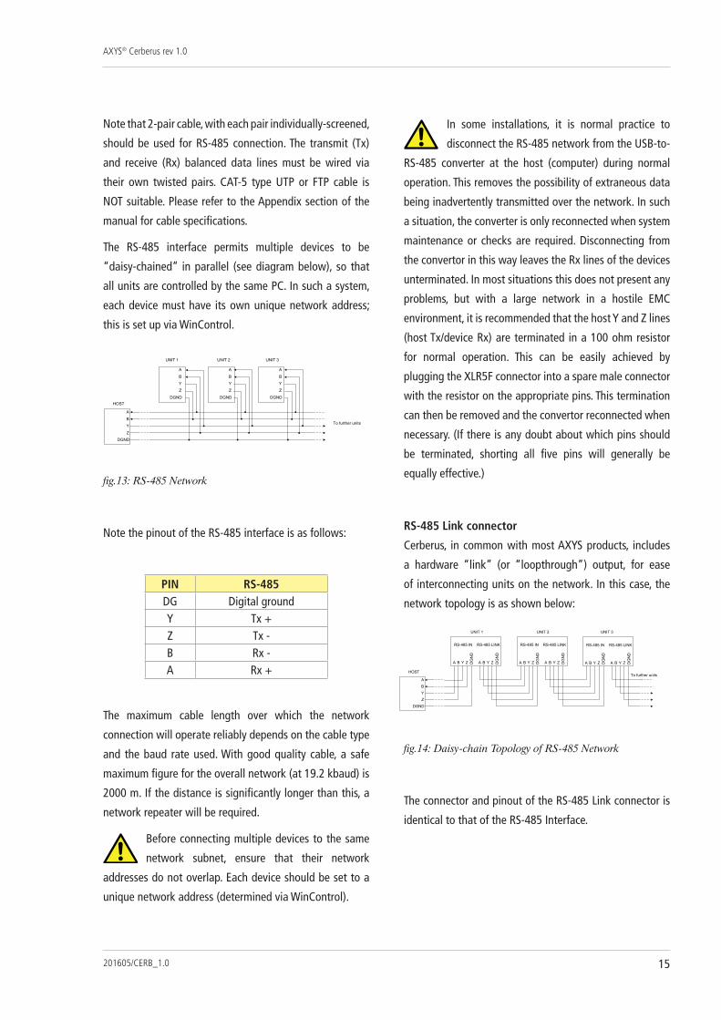
The RS-485 interface permits multiple devices to be
“daisy-chained” in parallel (see diagram below), so that
all units are controlled by the same PC. In such a system,
each device must have its own unique network address;
this is set up via WinControl.
fig.13: RS-485 Network
Note the pinout of the RS-485 interface is as follows:
PIN RS-485DG Digital groundY Tx +Z Tx -B Rx -A Rx +
The maximum cable length over which the network
connection will operate reliably depends on the cable type
and the baud rate used. With good quality cable, a safe
maximum figure for the overall network (at 19.2 kbaud) is
2000 m. If the distance is significantly longer than this, a
network repeater will be required.
Before connecting multiple devices to the same
network subnet, ensure that their network
addresses do not overlap. Each device should be set to a
unique network address (determined via WinControl).
In some installations, it is normal practice to
disconnect the RS-485 network from the USB-to-
RS-485 converter at the host (computer) during normal
operation. This removes the possibility of extraneous data
being inadvertently transmitted over the network. In such
a situation, the converter is only reconnected when system
maintenance or checks are required. Disconnecting from
the convertor in this way leaves the Rx lines of the devices
unterminated. In most situations this does not present any
problems, but with a large network in a hostile EMC
environment, it is recommended that the host Y and Z lines
(host Tx/device Rx) are terminated in a 100 ohm resistor
for normal operation. This can be easily achieved by
plugging the XLR5F connector into a spare male connector
with the resistor on the appropriate pins. This termination
can then be removed and the convertor reconnected when
necessary. (If there is any doubt about which pins should
be terminated, shorting all five pins will generally be
equally effective.)
RS-485 link connector
Cerberus, in common with most AXYS products, includes
a hardware “link” (or “loopthrough”) output, for ease
of interconnecting units on the network. In this case, the
network topology is as shown below:
fig.14: Daisy-chain Topology of RS-485 Network
The connector and pinout of the RS-485 Link connector is
identical to that of the RS-485 Interface.

AXYS® Cerberus rev 1.0
201605/CERB_1.016
Failure relay
Cerberus provides a two-pole changeover relay whose
contacts are accessible on two 3-pin 3.81 mm-pitch
screw-terminal connectors. The two poles are electrically
independent, and are marked ‘A’ and ‘B’ on the rear panel.
The pins are labelled CO (changeover), NC (normally-
closed) and NO (normally-open).
Note that in this case, ‘NO’ and ‘NC’ refer to the relay states
as applied to the Cerberus in normal use; ‘NC’ is connected
to ‘CO’ while the unit is powered and operating normally;
in the event of a fault condition, ‘CO’ is connected to ‘NO’.
fig.15: Failure Relay
The conditions under which the relay operates are defined
as part of the unit configuration in WinControl, and may
include network failure, short or open circuit detection at
any digital input, out-of-range voltages at the analogue
inputs, and so on.
Each set of contacts has maximum current and voltage
ratings of 100 mA and 24 V respectively.
STATUS lEDS
The front panel carries a set of five LEDs showing the
status of various unit functions. From left to right:
Power supply OK (green) [2]: illuminates when the
Cerberus is switched on and the PSU is functioning
normally.
Status external failure relay (bi-colour) [3]: normally
green, indicating no fault state exists; turns red to indicate
that a fault condition has de-energised the failure relay.
The conditions defining a failure are set up via WinControl.
Identification (green) [4]: This LED can be illuminated
temporarily (“pinged”) from WinControl. This feature is
provided so that in an installation using multiple AXYS
units, each particular physical unit can be positively
identified if necessary.
RS-485 Send (orange) [5]: indicates that the Cerberus is
transmitting data to the RS-485 network.
RS-485 Receive (orange) [6]: indicates that the Cerberus
is receiving data from the RS-485 network.
AXYS® Cerberus rev 1.0
201605/CERB_1.0 17
CONFIGURING CERBERUS wITH wINCONTROl
The AXYS WinControl software runs on any PC and allows
full control and monitoring of all AXYS products on the
RS-485 network connected to it (normally via a USB-to-
RS-485 interface).
A full description of the operation and use of WinControl
is beyond the scope of this manual. WinControl is supplied
with an extremely comprehensive set of context-sensitive
Help files; please see these for more detailed information.
However, a general overview of WinControl as applied to
Cerberus is given below.
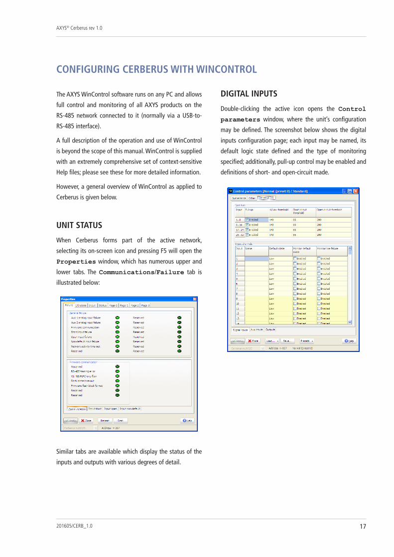
UNIT STATUS
When Cerberus forms part of the active network,
selecting its on-screen icon and pressing F5 will open the
Properties window, which has numerous upper and
lower tabs. The Communications/Failure tab is
illustrated below:
Similar tabs are available which display the status of the
inputs and outputs with various degrees of detail.
DIGITAl INPUTS
Double-clicking the active icon opens the Control
parameters window, where the unit’s configuration
may be defined. The screenshot below shows the digital
inputs configuration page; each input may be named, its
default logic state defined and the type of monitoring
specified; additionally, pull-up control may be enabled and
definitions of short- and open-circuit made.

AXYS® Cerberus rev 1.0
201605/CERB_1.018
ANAlOGUE INPUTS
WinControl allows adjustment of the upper and lower
thresholds, between which the input voltage at the
analogue inputs should remain under no-fault conditions.
OUTPUTS
Each output relay may be configured to activate either as
the result of a defined fault condition, or in response to a
network command.
SURVEIllANCE FUNCTIONS
This page allows definition of the conditions under which
the failure relay changes state.

AXYS® Cerberus rev 1.0
201605/CERB_1.0 19
APPENDIx
TECHNICAl SPECIFICATIONS
Full technical specifications of the AXYS Cerberus are
available at:
http://www.duran-audio.com
MAINTENANCE AND wARRANTY INFORMATION
Maintenance
Maintenance should only be performed by qualified service
personnel. In case of doubt, always contact your dealer. For
cleaning, use non-abrasive and non-aggressive household
cleaning agents only.
warranty Information
This AXYS Cerberus is covered by Duran Audio’s standard
product warranty, and is subject to the terms and conditions
of the warranty. Please consult www.duran-audio.com for
a full statement of warranty policy.
SOFTwARE AND FIRMwARE UPDATES
The AXYS WinControl application is freely available
and can be downloaded from the download area of our
website: www.duran-audio.com. We advise installers,
users and engineers to check our site regularly for updates.
Intellivox firmware and DSP software upgrades will
also be made available through the website. For further
information about how to use WinControl please refer to
the WinControl Help files.
NETwORK CABlES
The type of cable necessary for correct operation of the
RS-485 network is twin twisted pair with each pair
individually shielded. Numerous cables of this type
are readily available and cables broadly meeting the
specifications of the example cable given below are likely
to be suitable.
Example of a preferred cable type:
Type BElDEN ‘Datalene’ series No . 9729 2-pair
Characteristic impedance 100 ohms
Capacitance (core to core) 41 pF/m
Capacitance (core to screen) 72.5 pF/m
DC resistance (core) 78.7 ohms/km
DC resistance (screen) 59.1 ohms/km

DURAN AUDIO BVKoxkampseweg 10, 5301 KK Zaltbommel, The Netherlands.
tel. +31 418 515583 fax. +31 418 518077http://www.duran-audio.com [email protected]