instruction manual bench oscillating spindle sander · properly secured on the spindle before...
TRANSCRIPT

INS
TRU
CTIO
NM
AN
UA
L
Bench Oscillating SpindleSander
(Model SA350)
PART NO. 906118 - 06-15-02Copyright © 2002 Delta Machinery
ESPAÑOL: PÁGINA 13To learn more about DELTA MACHINERY visit our website at: www.deltamachinery.com.For Parts, Service, Warranty or other Assistance,
please call 1-800-223-7278 (In Canada call 1-800-463-3582).
33952
RTD10000124AA
Downloaded from www.Manualslib.com manuals search engine

2
GENERAL SAFETY RULESWoodworking can be dangerous if safe and proper operating procedures are not followed. As with all machinery, thereare certain hazards involved with the operation of the product. Using the machine with respect and caution willconsiderably lessen the possibility of personal injury. However, if normal safety precautions are overlooked or ignored,personal injury to the operator may result. Safety equipment such as guards, push sticks, hold-downs, featherboards,goggles, dust masks and hearing protection can reduce your potential for injury. But even the best guard won’t makeup for poor judgment, carelessness or inattention. Always use common sense and exercise caution in the workshop.If a procedure feels dangerous, don’t try it. Figure out an alternative procedure that feels safer. REMEMBER: Yourpersonal safety is your responsibility.
This machine was designed for certain applications only. Delta Machinery strongly recommends that this machine notbe modified and/or used for any application other than that for which it was designed. If you have any questions relativeto a particular application, DO NOT use the machine until you have first contacted Delta to determine if it can or shouldbe performed on the product.
Technical Service ManagerDelta Machinery4825 Highway 45 NorthJackson, TN 38305
(IN CANADA: 505 SOUTHGATE DRIVE, GUELPH, ONTARIO N1H 6M7)
WARNING: FAILURE TO FOLLOW THESE RULES MAY RESULT IN SERIOUS PERSONAL INJURY
1. FOR YOUR OWN SAFETY, READ INSTRUCTIONMANUAL BEFORE OPERATING THE TOOL. Learn thetool’s application and limitations as well as the specifichazards peculiar to it.
2. KEEP GUARDS IN PLACE and in working order.3. ALWAYS WEAR EYE PROTECTION. Wear safety
glasses. Everyday eyeglasses only have impact resistantlenses; they are not safety glasses. Also use face or dustmask if cutting operation is dusty. These safety glassesmust conform to ANSI Z87.1 requirements. NOTE:Approved glasses have Z87 printed or stamped on them.
4. REMOVE ADJUSTING KEYS AND WRENCHES. Formhabit of checking to see that keys and adjusting wrenchesare removed from tool before turning it “on”.
5. KEEP WORK AREA CLEAN. Cluttered areas andbenches invite accidents.
6. DON’T USE IN DANGEROUS ENVIRONMENT. Don’tuse power tools in damp or wet locations, or expose themto rain. Keep work area well-lighted.
7. KEEP CHILDREN AND VISITORS AWAY. All childrenand visitors should be kept a safe distance from work area.
8. MAKE WORKSHOP CHILDPROOF – with padlocks,master switches, or by removing starter keys.
9. DON’T FORCE TOOL. It will do the job better and besafer at the rate for which it was designed.10. USE RIGHT TOOL. Don’t force tool or attachment todo a job for which it was not designed.11. WEAR PROPER APPAREL. No loose clothing, gloves,neckties, rings, bracelets, or other jewelry to get caught inmoving parts. Nonslip footwear is recommended. Wearprotective hair covering to contain long hair.12. SECURE WORK. Use clamps or a vise to hold workwhen practical. It’s safer than using your hand and freesboth hands to operate tool.13. DON’T OVERREACH . Keep proper footing andbalance at all times.14. MAINTAIN TOOLS IN TOP CONDITION. Keep toolssharp and clean for best and safest performance. Followinstructions for lubricating and changing accessories.15. DISCONNECT TOOLS before servicing and whenchanging accessories such as blades, bits, cutters, etc.16. USE RECOMMENDED ACCESSORIES. The use ofaccessories and attachments not recommended by Deltamay cause hazards or risk of injury to persons.17. REDUCE THE RISK OF UNINTENTIONAL STARTING.Make sure switch is in “OFF” position before plugging inpower cord. In the event of a power failure, move switchto the “OFF” position.
18. NEVER STAND ON TOOL. Serious injury could occur ifthe tool is tipped or if the cutting tool is accidentallycontacted.19. CHECK DAMAGED PARTS. Before further use of thetool, a guard or other part that is damaged should becarefully checked to ensure that it will operate properly andperform its intended function – check for alignment ofmoving parts, binding of moving parts, breakage of parts,mounting, and any other conditions that may affect itsoperation. A guard or other part that is damaged should beproperly repaired or replaced.20. DIRECTION OF FEED. Feed work into a blade orcutter against the direction of rotation of the blade or cutteronly.21. NEVER LEAVE TOOL RUNNING UNATTENDED.TURN POWER OFF. Don’t leave tool until it comes to acomplete stop.22. STAY ALERT, WATCH WHAT YOU ARE DOING, ANDUSE COMMON SENSE WHEN OPERATING A POWERTOOL. DO NOT USE TOOL WHILE TIRED OR UNDERTHE INFLUENCE OF DRUGS, ALCOHOL, ORMEDICATION. A moment of inattention while operatingpower tools may result in serious personal injury.23. MAKE SURE TOOL IS DISCONNECTED FROMPOWER SUPPLY whi le motor is be ing mounted,connected or reconnected.24. THE DUST GENERATED by certain woods and woodproducts can be injurious to your health. Always operatemachinery in well ventilated areas and provide for properdust removal. Use wood dust collection systems wheneverpossible.25. WARNING: SOME DUST CREATED BYPOWER SANDING, SAWING, GRINDING, DRILLING,AND OTHER CONSTRUCTION ACTIVITIES containschemicals known to cause cancer, birth defects or otherreproductive harm. Some examples of these chemicalsare:· lead from lead-based paints,· crystalline silica from bricks and cement and other
masonry products, and· arsenic and chromium from chemically-treated lumber. Your risk from these exposures varies, depending on howoften you do this type of work. To reduce your exposureto these chemicals: work in a well ventilated area, andwork with approved safety equipment, such as thosedust masks that are specially designed to filter outmicroscopic particles.
SAVE THESE INSTRUCTIONS. Refer to them often and use them to instruct others.
Downloaded from www.Manualslib.com manuals search engine

ADDITIONAL SAFETY RULES FOROSCILLATING SPINDLE SANDERS
3
WARNING: FAILURE TO FOLLOW THESE RULES MAY RESULT IN SERIOUS PERSONAL INJURY.
SAVE THESE INSTRUCTIONS. Refer to them often
and use them to instruct others.
1. DO NOT OPERATE THIS MACHINE until it isassembled and installed according to the instructions.
2. OBTAIN ADVICE FROM YOUR SUPERVISOR,instructor, or another qualified person if you are notfamiliar with the operation of this machine.
3. FOLLOW ALL WIRING CODES and recommendedelectrical connections.
4. KEEP fingers away from rotating sanding drum.
5. MAKE SURE sanding drum is not damaged and isproperly secured on the spindle before operating.
6. NEVER perform layout, assembly or set-up work onthe table while the machine is running.
7. MAKE SURE workpiece is clear of sanding drumbefore turning unit on.
8. NEVER use machine for wet sanding which cancreate hazard of electrical shock.
9. KEEP TABLE INSERT IN PLACE. Use correctlysized table insert for each sanding sleeve. Maintainminimum table opening to keep fingers from beingpinched or workpiece being pulled down.
10. DO NOT sand near flammable liquids, vapors, orgases.
11. USE sander on a solid supporting surface wherethere is plenty of room for handling and supportingworkpiece.
12. WHEN installing sanding drums, washers, etc., besure they are tight without any excessive play.
13. ALWAYS feed workpiece against the direction of thesanding drum rotation.
14. CLEAR all debris from table before sanding theworkpiece.
15. MAKE CERTAIN that workpiece is properlysupported. Use extra caution when sanding smallpieces.
16. DO NOT sand pieces too small to be held by hand.
17. AFTER turning off power switch, disconnect toolfrom power source and wait for spindle to stop beforeservicing, adjusting or changing spindles.
18. TURN THE MACHINE “OFF” AND DISCONNECTTHE MACHINE from the power source before installingor removing accessories, before adjusting or changingset-ups, or when making repairs.
19. TURN THE MACHINE “OFF”, disconnect themachine from the power source, and clean thetable/work area before leaving the machine. LOCK THESWITCH IN THE “OFF” POSITION to preventunauthorized use.
20. ADDITIONAL INFORMATION regarding the safeand proper operation of this tool is available from thePower Tool Institute, 1300 Summer Avenue, Cleveland,OH 44115-2851. Information is also available from theNational Safety Council, 1121 Spring Lake Drive, Itasca,IL 60143-3201. Please refer to the American NationalStandards Institute ANSI 01.1 Safety Requirements forWoodworking Machines and the U.S. Department ofLabor OSHA 1910.213 Regulations.
Downloaded from www.Manualslib.com manuals search engine

4
POWER CONNECTIONSA separate electrical circuit should be used for your machines. This circuit should not be less than #12 wire and shouldbe protected with a 20 Amp time lag fuse. If an extension cord is used, use only 3-wire extension cords which have 3-prong grounding type plugs and matching receptacle which will accept the machine’s plug. Before connecting themotor to the power line, make sure the switch is in the “OFF” position and be sure that the electric current is of thesame characteristics as indicated on the machine. All line connections should make good contact. Running on lowvoltage will damage the motor.
WARNING: DO NOT EXPOSE THE MACHINE TO RAIN OR OPERATE THE MACHINE IN DAMP LOCATIONS.
MOTOR SPECIFICATIONSYour machine is wired for 120 volt, 60 HZ alternating current. Before connecting the machine to the power source,make sure the switch is in the “OFF” position.
GROUNDING INSTRUCTIONSWARNING: THIS MACHINE MUST BE GROUNDED WHILE IN USE TO PROTECT THE OPERATOR FROMELECTRIC SHOCK.
Fig. A Fig. B
GROUNDED OUTLET BOX
CURRENTCARRYING
PRONGS
GROUNDING BLADEIS LONGEST OF THE 3 BLADES
GROUNDED OUTLET BOX
GROUNDINGMEANS
ADAPTER
2. Grounded, cord-connected machines intended for useon a supply circuit having a nominal rating less than 150volts:
If the machine is intended for use on a circuit that has anoutlet that looks like the one illustrated in Fig. A, themachine will have a grounding plug that looks like the plugillustrated in Fig. A. A temporary adapter, which looks likethe adapter illustrated in Fig. B, may be used to connectthis plug to a matching 2-conductor receptacle as shownin Fig. B if a properly grounded outlet is not available. Thetemporary adapter should be used only until a properlygrounded outlet can be installed by a qualified electrician.The green-colored rigid ear, lug, and the like, extendingfrom the adapter must be connected to a permanentground such as a properly grounded outlet box. Wheneverthe adapter is used, it must be held in place with a metalscrew.
NOTE: In Canada, the use of a temporary adapter is notpermitted by the Canadian Electric Code.
WARNING: IN ALL CASES, MAKE CERTAIN THE RECEPTACLE IN QUESTION IS PROPERLY
GROUNDED. IF YOU ARE NOT SURE HAVE AQUALIFIED ELECTRICIAN CHECK THE RECEPTACLE.
1. All grounded, cord-connected machines:
In the event of a malfunction or breakdown, groundingprovides a path of least resistance for electric current toreduce the risk of electric shock. This machine isequipped with an electric cord having an equipment-grounding conductor and a grounding plug. The plug mustbe plugged into a matching outlet that is properly installedand grounded in accordance with all local codes andordinances.
Do not modify the plug provided - if it will not fit the outlet,have the proper outlet installed by a qualified electrician.
Improper connection of the equipment-groundingconductor can result in risk of electric shock. Theconductor with insulation having an outer surface that isgreen with or without yellow stripes is the equipment-grounding conductor. If repair or replacement of theelectric cord or plug is necessary, do not connect theequipment-grounding conductor to a live terminal.
Check with a qualified electrician or service personnel ifthe grounding inst ruct ions are not complete lyunderstood, or if in doubt as to whether the machine isproperly grounded.
Use only 3-wire extension cords that have 3-pronggrounding type plugs and matching 3-conductorreceptacles that accept the machine’s plug, as shown inFig. A.
Repair or replace damaged or worn cord immediately.
Downloaded from www.Manualslib.com manuals search engine

Use proper extension cords. Make sure your extension cord is in good condition and is a 3-wire extension cord whichhas a 3-prong grounding type plug and matching receptacle which will accept the machine’s plug. When using anextension cord, be sure to use one heavy enough to carry the current of the machine. An undersized cord will causea drop in line voltage, resulting in loss of power and overheating. Fig. D, shows the correct gauge to use dependingon the cord length. If in doubt, use the next heavier gauge. The smaller the gauge number, the heavier the cord.
EXTENSION CORDS
OPERATING INSTRUCTIONSFOREWORD
The Delta ShopMaster Model SA350 has a large 18" diameter cast-iron table, to support large workpieces. Themachine has a heavy-duty motor assembly, which features a 1/4 H.P. induction motor with direct drive for quiet, andsmooth operation.
UNPACKING AND CLEANINGCarefully unpack the machine and all loose items from the shipping container(s). Remove the protective coating fromall unpainted surfaces. This coating may be removed with a soft cloth moistened with kerosene (do not use acetone,gasoline or lacquer thinner for this purpose). After cleaning, cover the unpainted surfaces with a good quality householdfloor paste wax.
NOTICE: THE MANUAL COVER PHOTO ILLUSTRATES THE CURRENTPRODUCTION MODEL. ALL OTHER ILLUSTRATIONS ARE REPRESENTATIVE
ONLY AND MAY NOT DEPICT THE ACTUAL COLOR, LABELING ORACCESSORIES AND MAY BE INTENDED TO ILLUSTRATE TECHNIQUE ONLY.
5
Fig. D
MINIMUM GAUGE EXTENSION CORDRECOMMENDED SIZES FOR USE WITH STATIONARY ELECTRIC MACHINES
Ampere Total Length Gauge ofRating Volts of Cord in Feet Extension Cord
0-6 120 up to 25 18 AWG0-6 120 25-50 16 AWG0-6 120 50-100 16 AWG0-6 120 100-150 14 AWG
6-10 120 up to 25 18 AWG6-10 120 25-50 16 AWG6-10 120 50-100 14 AWG6-10 120 100-150 12 AWG
10-12 120 up to 25 16 AWG10-12 120 25-50 16 AWG10-12 120 50-100 14 AWG10-12 120 100-150 12 AWG
12-16 120 up to 25 14 AWG12-16 120 25-50 12 AWG12-16 120 GREATER THAN 50 FEET NOT RECOMMENDED
Downloaded from www.Manualslib.com manuals search engine

6
BENCH OSCILLATING SPINDLE SANDER PARTS
Fig. 2
1. Bench Oscillating Spindle Sander
2. Spindle Adapter
3. 1" I.D. Table Insert
4. 1-3/4" O.D. Drum Washer
5. Arbor Screw
6. 3/4" Sanding Drum & 3/4” Abrasive Sleeve
7. 3/16" Allen Wrench
8. 1/2" Socket Wrench
9. Dust Bag
1
2
3
4
56
7
8
9
Downloaded from www.Manualslib.com manuals search engine
7
ASSEMBLYWARNING: FOR YOUR OWN SAFETY, DO NOT CONNECT THE MACHINE TO THE POWER SOURCE UNTIL
THE MACHINE IS COMPLETELY ASSEMBLED. DO NOT OPERATE THIS MACHINE UNTIL YOU READ ANDUNDERSTAND THE ENTIRE INSTRUCTION MANUAL
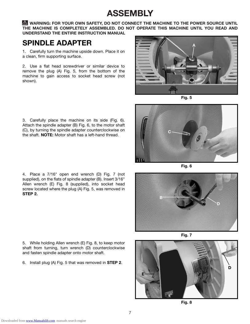
SPINDLE ADAPTER1. Carefully turn the machine upside down. Place it ona clean, firm supporting surface.
2. Use a flat head screwdriver or similar device toremove the plug (A) Fig. 5, from the bottom of themachine to gain access to socket head screw (notshown).
3. Carefully place the machine on its side (Fig. 6).Attach the spindle adapter (B) Fig. 6, to the motor shaft(C), by turning the spindle adapter counterclockwise onthe shaft. NOTE: Motor shaft has a left-hand thread.
4. Place a 7/16" open end wrench (D) Fig. 7 (notsupplied), on the flats of spindle adapter (B). Insert 3/16"Allen wrench (E) Fig. 8 (supplied), into socket headscrew located where the plug (A) Fig. 5, was removed inSTEP 2.
5. While holding Allen wrench (E) Fig. 8, to keep motorshaft from turning, turn wrench (D) counterclockwiseand fasten spindle adapter onto motor shaft.
6. Install plug (A) Fig. 5 that was removed in STEP 2.
Fig. 5
A
Fig. 6
C
Fig. 7
B
D
Fig. 8
E
D
Downloaded from www.Manualslib.com manuals search engine

8
SANDING DRUM, ABRASIVESLEEVE AND TABLE INSERT1. Place 1-3/4" drum washer (A) Fig. 10, on the spindleadapter (B).2. Slide the abrasive sleeve (C) Fig. 10 over thesanding drum (D), and place the sanding drum (D) Fig.11, with the sleeve on the spindle adapter. Fasten with a5/16" screw (E) Fig. 10, using the socket wrench (F)supplied. NOTE: Turn the screw (E) Fig. 10, counter-clockwise to tighten and clockwise to loosen.3. Place the table insert (G) Figs. 11 & 12 over abrasivesleeve (C) and onto the table. NOTE: Arrows on the tableinsert indicate the top surface.4. Compartments (H) Fig. 12, on the sides of thesander can be used for storing work pieces oraccessories.
Fig. 10
A
B
C
D
E
F
G
Fig. 11
F
D G
Fig. 12
H H
C
G
DUST BAG1. A 1-1/2" I.D. dust chute (A) Fig. 13, is supplied withthe spindle sander to accept the dust bag.2. To attach the dust bag (B) Fig. 14, to the dust chute(A), squeeze the spring clamp on the dust bag and slideit over the dust chute. Release clamp.
Fig. 13
Fig. 14
A
B
FASTENING SANDER TOSUPPORTING SURFACEIMPORTANT: If the machine has a tendency to tip overor to walk on the supporting surface, the machine mustbe secured to the supporting surface. Use the fourholes, three of which are shown at (A) Fig. 15 to attachthe machine to the supporting surface.
Fig. 15
AA
Downloaded from www.Manualslib.com manuals search engine
9
OPERATING CONTROLS AND ADJUSTMENTS
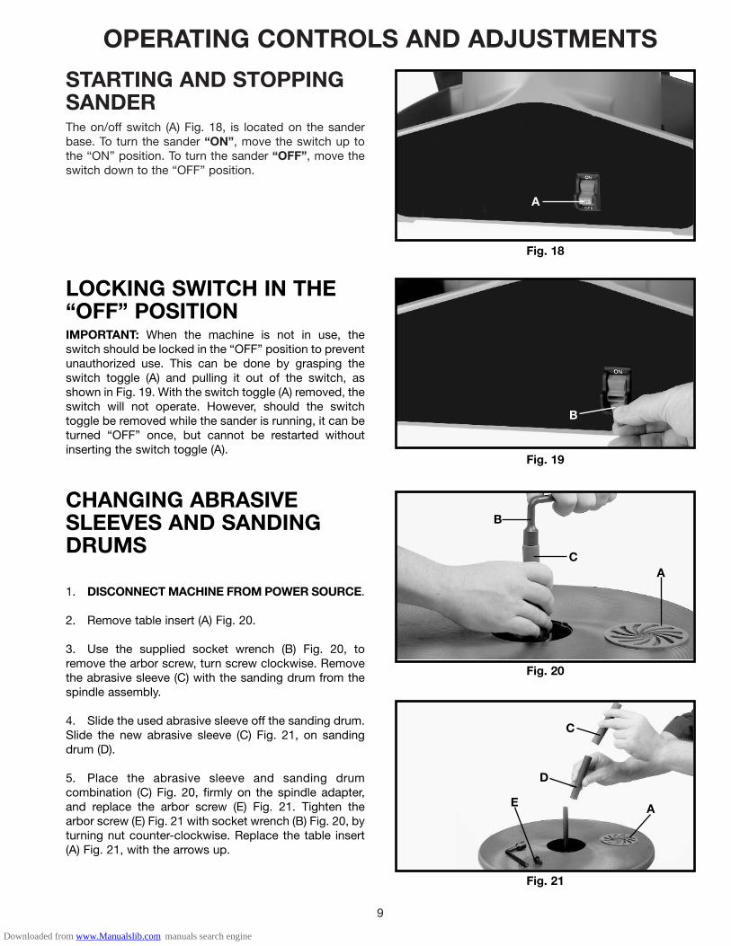
STARTING AND STOPPINGSANDERThe on/off switch (A) Fig. 18, is located on the sanderbase. To turn the sander “ON”, move the switch up tothe “ON” position. To turn the sander “OFF”, move theswitch down to the “OFF” position.
Fig. 18
A
LOCKING SWITCH IN THE“OFF” POSITIONIMPORTANT: When the machine is not in use, theswitch should be locked in the “OFF” position to preventunauthorized use. This can be done by grasping theswitch toggle (A) and pulling it out of the switch, asshown in Fig. 19. With the switch toggle (A) removed, theswitch will not operate. However, should the switchtoggle be removed while the sander is running, it can beturned “OFF” once, but cannot be restarted withoutinserting the switch toggle (A).
Fig. 19
B
CHANGING ABRASIVESLEEVES AND SANDINGDRUMS
1. DISCONNECT MACHINE FROM POWER SOURCE.
2. Remove table insert (A) Fig. 20.
3. Use the supplied socket wrench (B) Fig. 20, toremove the arbor screw, turn screw clockwise. Removethe abrasive sleeve (C) with the sanding drum from thespindle assembly.
4. Slide the used abrasive sleeve off the sanding drum.Slide the new abrasive sleeve (C) Fig. 21, on sandingdrum (D).
5. Place the abrasive sleeve and sanding drumcombination (C) Fig. 20, firmly on the spindle adapter,and replace the arbor screw (E) Fig. 21. Tighten thearbor screw (E) Fig. 21 with socket wrench (B) Fig. 20, byturning nut counter-clockwise. Replace the table insert(A) Fig. 21, with the arrows up.
Fig. 20
Fig. 21
A
B
C
C
D
E A
Downloaded from www.Manualslib.com manuals search engine
10
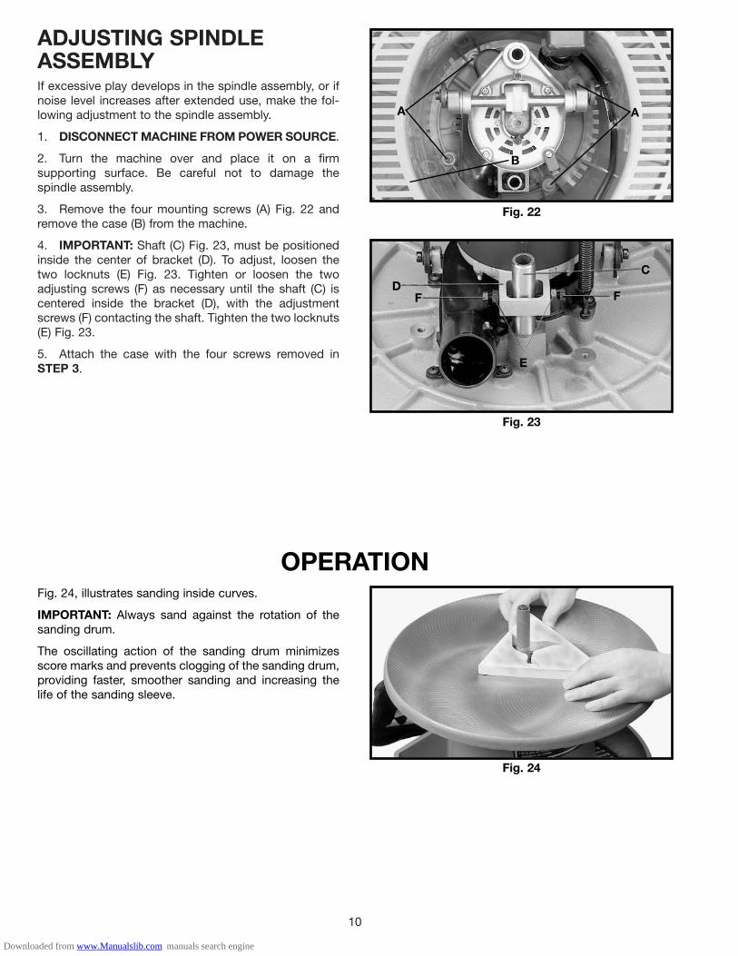
ADJUSTING SPINDLEASSEMBLYIf excessive play develops in the spindle assembly, or ifnoise level increases after extended use, make the fol-lowing adjustment to the spindle assembly.
1. DISCONNECT MACHINE FROM POWER SOURCE.
2. Turn the machine over and place it on a firmsupporting surface. Be careful not to damage thespindle assembly.
3. Remove the four mounting screws (A) Fig. 22 andremove the case (B) from the machine.
4. IMPORTANT: Shaft (C) Fig. 23, must be positionedinside the center of bracket (D). To adjust, loosen thetwo locknuts (E) Fig. 23. Tighten or loosen the twoadjusting screws (F) as necessary until the shaft (C) iscentered inside the bracket (D), with the adjustmentscrews (F) contacting the shaft. Tighten the two locknuts(E) Fig. 23.
5. Attach the case with the four screws removed inSTEP 3.
Fig. 22
A A
Fig. 23
B
E
F F
CD
OPERATIONFig. 24, illustrates sanding inside curves.
IMPORTANT: Always sand against the rotation of thesanding drum.
The oscillating action of the sanding drum minimizesscore marks and prevents clogging of the sanding drum,providing faster, smoother sanding and increasing thelife of the sanding sleeve.
Fig. 24
Downloaded from www.Manualslib.com manuals search engine

11
MAINTENANCEAfter 100 hours of use, the grease in the gear housingshould be checked and changed.
To gain access to the gear housing:
1. DISCONNECT MACHINE FROM POWER SOURCE.
2. Turn the machine over and loosen the two screws(A) Fig. 25, and remove the cover (B).
3. Remove the old grease and repack the gears withnew grease.
4. Replace the cover.
Fig. 25
A B
Downloaded from www.Manualslib.com manuals search engine

Two Year Limited WarrantyDelta will repair or replace, at its expense and at its option, any Delta machine, machine part, or machine accessory whichin normal use has proven to be defective in workmanship or material, provided that the customer returns the productprepaid to a Delta factory service center or authorized service station with proof of purchase of the product within twoyears and provides Delta with reasonable opportunity to verify the alleged defect by inspection. Delta may require thatelectric motors be returned prepaid to a motor manufacturer’s authorized station for inspection and repair or replacement.Delta will not be responsible for any asserted defect which has resulted from normal wear, misuse, abuse or repair oralteration made or specifically authorized by anyone other than an authorized Delta service facility or representative. Underno circumstances will Delta be liable for incidental or consequential damages resulting from defective products. Thiswarranty is Delta’s sole warranty and sets forth the customer’s exclusive remedy, with respect to defective products; allother warranties, express or implied, whether of merchantability, fitness for purpose, or otherwise, are expresslydisclaimed by Delta.
Printed in U.S.A.
PARTS, SERVICE OR WARRANTY ASSISTANCEAll Delta Machines and accessories are manufactured to high quality standards and are serviced by a networkof Porter-Cable • Delta Factory Service Centers and Delta Authorized Service Stations. To obtain additionalinformation regarding your Delta quality product or to obtain parts, service, warranty assistance, or the locationof the nearest service outlet, please call 1-800-223-7278 (In Canada call 1-800-463-3582).
ACCESSORIESA complete line of accessories is available from your Delta Supplier, Porter-Cable • Delta Factory Service Centers,and Delta Authorized Service Stations. Please visit our Web Site www.deltamachinery.com for a catalog orfor the name of your nearest supplier.
WARNING: Since accessories other than those offered by Delta have not been tested with this product, use of such accessories could be hazardous. For safest operation, only Delta recommended accessories should be used with this product.
12
Downloaded from www.Manualslib.com manuals search engine