instruction manual - earthing, lightning & surge
TRANSCRIPT

Instruction ManualIsolated Downconductor System
Model ISODC & AccessoriesFor Isolated Lightning Protection using
IEC 62305 Separation Distances
WARNING:
Due to ongoing research into the phenomena of lightning, lightning protection technology and product improvement, ERICO® reserves the right toalter any information and specifications contained herein at any time without notice.
2www.erico.com
The ERITECH® Isolated Downconductor is a specialized lightning protection downconductor, that during operation may be subjected to impulse currents of over 100,000 Amps and voltage of up to 700,000 V may be developed.
Reliable operation is dependent upon correct design and installation in accordance with IEC 62305 series and ERICO instructions. The Isolated Downconductor must not be damaged in handling, installation or service. The downconductor sheath is a specialized semi-conductivematerial requiring electrical bonding to the structure. This sheath is fragile and damage to the sheath may require replacement of the cable.
Fully refer to installation instructions prior to handling and installation. Do not assume that traditional lightning protection or HV cable practices apply.
These products should be installed as part of a IEC 62305 series integrated lightning protection system.
No lightning protection system offers 100% protection against all lightning events. However, correct installation is essential for the maximum level of safety.
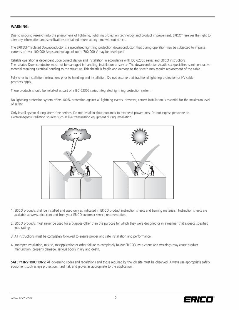
Only install system during storm-free periods. Do not install in close proximity to overhead power lines. Do not expose personnel to electromagnetic radiation sources such as live transmission equipment during installation.
1. ERICO products shall be installed and used only as indicated in ERICO product instruction sheets and training materials. Instruction sheets are available at www.erico.com and from your ERICO customer service representative.
2. ERICO products must never be used for a purpose other than the purpose for which they were designed or in a manner that exceeds specified load ratings.
3. All instructions must be completely followed to ensure proper and safe installation and performance.
4. Improper installation, misuse, misapplication or other failure to completely follow ERICO’s instructions and warnings may cause product malfunction, property damage, serious bodily injury and death.
SAFETY INSTRUCTIONS: All governing codes and regulations and those required by the job site must be observed. Always use appropriate safetyequipment such as eye protection, hard hat, and gloves as appropriate to the application.

3www.erico.com
TABLE OF CONTENTS
1. DESIGN ........................................................................................................................ 4
2. GENERAL ASSEMBLY PROCEDURE .................................................................................. 8
3. ASSEMBLY OF ISOLATED MAST ..................................................................................... 9
4. FIXING ISOLATED MAST TO THE STRUCTURE ................................................................. 11
5. SECURING THE ISOLATED DOWNCONDUCTOR ............................................................ 13
6. FITTING LOWER TERMINATION ADAPTER ..................................................................... 14
7. CONNECTION OF LOWER TERMINATION ADAPTER ...................................................... 15
8. ISODC PRIMARY EQUIPOTENTIAL BOND ....................................................................... 15
9. LIGHTNING EVENT COUNTER ...................................................................................... 16
10. TESTING AND MAINTENANCE ..................................................................................... 16
11. UPPER TERMINATION PROCEDURE ...............................................................................16
12. GENERAL SPECIFICATIONS ............................................................................................17
ANNEX A: ISODUAL DUAL COUPLING ............................................................................... 18
ANNEX B: ERITECH® SYSTEM 3000 MAST AND SUPPORT HARDWARE .............................. 19
4www.erico.com
Design requirements of the ERITECH® Isolated Downconductor system is based on two sections of the IEC 62305-3 standard“Protection Against Lightning – Part 3: Physical damage to structures and life hazard”. For correct installation the system must bedesigned and installed in accordance with these requirements.
Step 1. Determine the required height of the air terminal to provide protection according to IEC 62305 Protection Angle Method (PAM)
Step 2. Determine the length of Isolated Downconductor so separation distance (IEC 62305-3 section 6.3) does not exceed 1000 mm
Step 3. Meet ERICO’s mounting and installation requirements and interconnect to a standard compliant grounding or lightning protection system
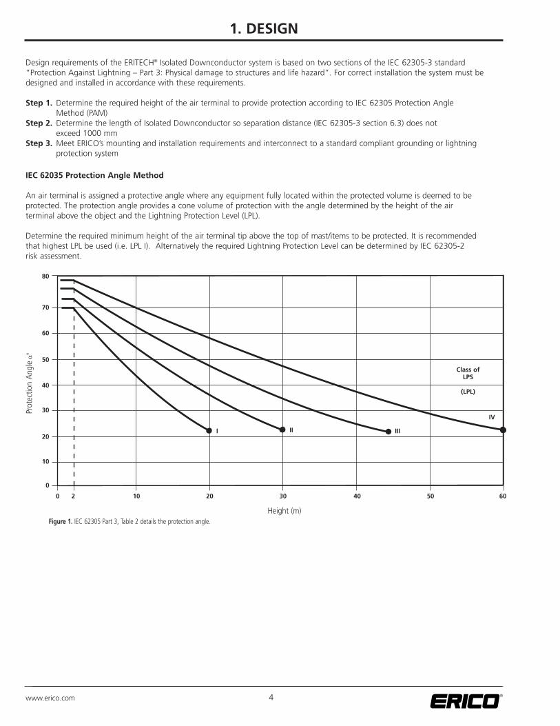
IEC 62035 Protection Angle Method
An air terminal is assigned a protective angle where any equipment fully located within the protected volume is deemed to be protected. The protection angle provides a cone volume of protection with the angle determined by the height of the air terminal above the object and the Lightning Protection Level (LPL).
Determine the required minimum height of the air terminal tip above the top of mast/items to be protected. It is recommended that highest LPL be used (i.e. LPL I). Alternatively the required Lightning Protection Level can be determined by IEC 62305-2 risk assessment.
80
70
60
50
40
30
20
10
0
0 10 20 30 40 50 602
I II III
IV
Class ofLPS
(LPL)
Height (m)
Prot
ectio
n A
ngle
��
Figure 1. IEC 62305 Part 3, Table 2 details the protection angle.
1. DESIGN
5www.erico.com
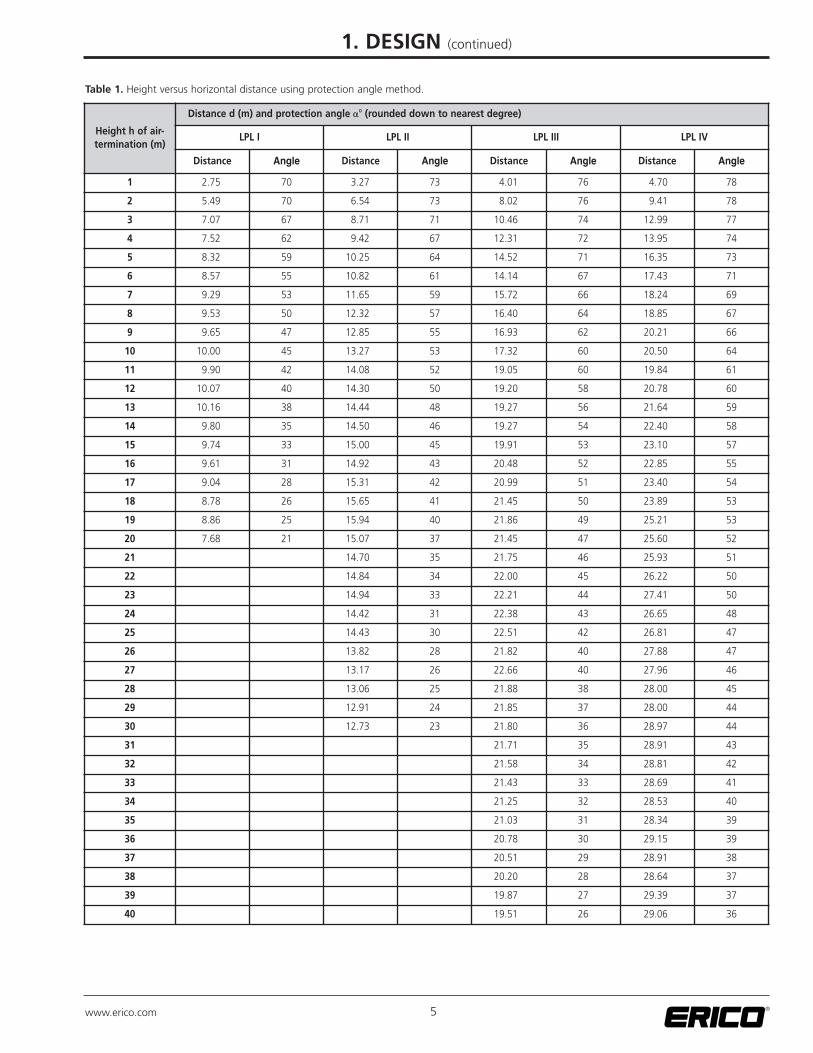
Table 1. Height versus horizontal distance using protection angle method.
Height h of air-termination (m)
Distance d (m) and protection angle �� (rounded down to nearest degree)
LPL I LPL II LPL III LPL IV
Distance Angle Distance Angle Distance Angle Distance Angle
1 2.75 70 3.27 73 4.01 76 4.70 78
2 5.49 70 6.54 73 8.02 76 9.41 78
3 7.07 67 8.71 71 10.46 74 12.99 77
4 7.52 62 9.42 67 12.31 72 13.95 74
5 8.32 59 10.25 64 14.52 71 16.35 73
6 8.57 55 10.82 61 14.14 67 17.43 71
7 9.29 53 11.65 59 15.72 66 18.24 69
8 9.53 50 12.32 57 16.40 64 18.85 67
9 9.65 47 12.85 55 16.93 62 20.21 66
10 10.00 45 13.27 53 17.32 60 20.50 64
11 9.90 42 14.08 52 19.05 60 19.84 61
12 10.07 40 14.30 50 19.20 58 20.78 60
13 10.16 38 14.44 48 19.27 56 21.64 59
14 9.80 35 14.50 46 19.27 54 22.40 58
15 9.74 33 15.00 45 19.91 53 23.10 57
16 9.61 31 14.92 43 20.48 52 22.85 55
17 9.04 28 15.31 42 20.99 51 23.40 54
18 8.78 26 15.65 41 21.45 50 23.89 53
19 8.86 25 15.94 40 21.86 49 25.21 53
20 7.68 21 15.07 37 21.45 47 25.60 52
21 14.70 35 21.75 46 25.93 51
22 14.84 34 22.00 45 26.22 50
23 14.94 33 22.21 44 27.41 50
24 14.42 31 22.38 43 26.65 48
25 14.43 30 22.51 42 26.81 47
26 13.82 28 21.82 40 27.88 47
27 13.17 26 22.66 40 27.96 46
28 13.06 25 21.88 38 28.00 45
29 12.91 24 21.85 37 28.00 44
30 12.73 23 21.80 36 28.97 44
31 21.71 35 28.91 43
32 21.58 34 28.81 42
33 21.43 33 28.69 41
34 21.25 32 28.53 40
35 21.03 31 28.34 39
36 20.78 30 29.15 39
37 20.51 29 28.91 38
38 20.20 28 28.64 37
39 19.87 27 29.39 37
40 19.51 26 29.06 36
1. DESIGN (continued)

6www.erico.com
Table 1. Height versus horizontal distance using protection angle method. (continued)
Height h of air-termination (m)
Distance d (m) and protection angle �� (rounded down to nearest degree)
LPL I LPL II LPL III LPL IV
Distance Angle Distance Angle Distance Angle Distance Angle
41 19.12 25 29.79 36
42 18.70 24 30.51 36
43 18.25 23 30.11 35
44 18.68 23 28.57 33
45 18.18 22 29.22 33
46 28.74 32
47 28.24 31
48 27.71 30
49 28.29 30
50 28.87 30
51 28.27 29
52 28.82 29
53 29.38 29
54 28.71 28
55 28.02 27
56 27.31 26
57 26.58 25
58 25.82 24
59 25.04 23
60 25.47 23
h1
d1
d2
h2
�1
Protected
Not Protected
Table 2. Lightning Protection Levels
Lightning Protection Level (Class of LPS)
Peak current (10/350 µs) Probability of exceedance
I 200 kA ≤ 1 %
II 150 kA ≤ 3 %
III 100 kA ≤ 9 %
IV 100 kA ≤ 16 %
1. DESIGN (continued)
�2

7www.erico.com
As shown in Figure 2, the ERITECH® Isolated Downconductor system requires two meters of clearance between the top of the isolated mast and mounting brackets/protected equipment. This two meter clearance is sufficient to prevent a flash-over betweennon-isolated air terminal and mast/object being protected.
IEC 62305 Electrical Insulation & Separation Distance
Equipment and structures can be protected by isolation, provided that the distance between the air terminal (or downconductor)and items to be protected are separated by a separation distance greater than:
∝°
Figure 2. Protection angle and two meter minimum Isolated Mast height.
1m
≥2m
S = ki lkckm
(IEC 62305-3 section 6.3, equation 4)
Where:
S separation distance, in meterski depends upon the selected class of LPSkc depends upon the lightning current flowing on the downconductors (kc = 1 for a single downconductor, 0.5 for two downconductors)km depends upon the electrical insulation material (km = 1 for air)l is the length, in meters, along the downconductor (from nearest equipotential bonding point, i.e. normally from lower termination), to the point where the separation distance is being considered.
1. DESIGN (continued)
Protected
Ki = Class of LPS (Lightning Protection Level)
0.08 I
0.06 II
0.04 III
0.04 IV
Table 3. ki versus Class of LPS.

8www.erico.com
The ISODC Isolated Downconductor has an equivalent separation distance of 1000 mm of air. Therefore simplifying the equation in Table 3, Table 4provides the maximum length for a single downconductor where the lower termination is equipotentially bonded to the structure. If it is not possibleto adhere to the distance limitations, then refer to Annex A for information on the ISODUAL dual coupling.
Class of LPS (Lightning Protection Level)
Maximum Isolated Downconductor length
I 12.5 m
II 16.6 m
III & IV 25 m
Table 4. Maximum Isolated Downconductor length for single equipotential bonded cable.
Where the lower termination is not equipotentially bonded to the structure, such as when connected to an isolated ring system, then distance mustbe measured to the nearest LPS-structural equipotential point. Contact ERICO® for advice.
1. DESIGN (continued)
Follow procedures appropriate for the site. However, it is generally recommended to:
1. Check sufficient Isolated Downconductor length is available for planned route.
2. Assemble the Isolated Mast, air terminal and Isolated Downconductor together, before mounting the arrangement to the structure.
3. Attach the mast mounting brackets to the structure.
4. Hoist and attach assembled mast/air terminal/downconductor arrangement to the structure.
5. Connect ISODC primary equipotential bond conductor to support mast.
6. Route and secure the Isolated Downconductor.
7. Cut bottom of Isolated Downconductor to final length, install lower termination and connect to grounding/lightning protection system.
2. GENERAL ASSEMBLY PROCEDURE

9www.erico.com
3. ASSEMBLY OF ISOLATED MAST
Use appropriate tools to securely assemble upper mast arrangement:
Step 1. Connect the 6 mm2 equipotential bonding conductor to the ISODC primary equipotential bond connector.Step 2. Feed the upper termination end of the ISODC Downconductor through the Isolated Mast. Make sure the ISODC
primary equipotential bond conductor is accessible from the bottom of the mast.
Primary Equipotential BondLower Termination Adapter
Upper Termination
Upper termination Adapter
Figure 3. Upper & lower termination adapter and ISODC primary equipotential bond connector.
Step 3. Loosely fit the 8 mm set screw into the hole on the side of the upper termination adapter (4 mm hex Allen key supplied). Do not insert to depth where set screw enters into threaded hole for air terminal.
Step 4. Insert the air terminal thread through pressure washer, ISOCAP50 body and fully screw into upper termination adapter. Refer to Figure 4. Ensure that hole for upper termination adapter-air terminal lock nut is aligned with access hole in ISOCAP50 body, tighten air terminal to 4 Nm.
Step 5. Tighten air terminal lock nut against pressure washer (4 Nm).Step 6. Apply LOCTITE® to the 8 mm set screw and tighten it into place against the air terminal with a torque of 8 Nm.Step 7. Fit ISOCAP50 body into Isolated Mast.

10www.erico.com
Threaded Locking Pin
ISOCAP50
Air Terminal
15 mm x 1 m Aluminum Rod
Lock Nut
Stainless Steel Washer
Mast Cap
Assembled ISODC
Isolated Mast
Figure 4. Upper mast arrangement.
3. ASSEMBLY OF ISOLATED MAST (continued)

11www.erico.com
The engineer responsible for the structure should first ensure that the mounting of the lightning protection system will not exceed the design parameters for the structure (e.g. wind and weight loading), nor exceed aviation or similar height limitations for the site. Galvanic suitability andmounting methods should be considered. The installation should be planned with appropriate access and safety equipment such as scaffolding, rigging and safety barriers etc. Appropriate precautions should be taken with regard to any potentially hazardous site conditions such as over-head or exposed power circuits or sources of electromagnetic radiation.
The Isolated Mast must be installed at a height where the angle-of-protection offered by the air terminal tip is sufficient to protect desired equipment. Additionally the minimum requirement of 2 m clearance must be maintained between the top of the Isolated Mast andstructure/object to be protected (refer to Figure 2).
Mast height above structure Mounting requirements Mast
2 - 2.5 m 2 brackets at least 400 mm apart ISOFRP3M Isolated 3 m mast
For taller mounting requirements ISOCAP68 and ERITECH® SYSTEM 3000 components can be used. Refer to Annex B
Table 5. Mast & mounting bracket requirements.
2-2.5 m(Minimum 2 m)
400 mm
Figure 5. Mast height and mounting arrangement.
4. FIXING ISOLATED MAST TO THE STRUCTURE
190 mm
30 mm
ALOF1GS OffsetMast Bracket
ISOMMB50Attachment
ACF-2-GSAttachment
MountingArrangements

The following illustrations show the mounting bracket fixing procedure.
1 Insert band. 2 Slip through loop. 3 Use tool to adjust.
4 Bend in place by moving down. 5 Pull the lever upward. 6 Secure by moving the tabs in place.
Figure 6. ISOMMB mounting brackets fixing procedure.
Do not slingat top ofterminal
Do not lift with more than 5 m ofdownconductorhanging frommast withouttying off tomast.
Stress removed from upper termination by securing downconductor to lower mast with flat webbing or otherappropriate sling.
Sling atmultiple points
Max 5 m
INCORRECT CORRECT
Figure 7. Incorrect and correct hauling methods.
4. FIXING ISOLATED MAST TO THE STRUCTURE (continued)
Do not use FIXOBAND for strapping Isolated Downconductor to the structure.
12www.erico.com

13www.erico.com
• It is not possible to join the Isolated Downconductor, so before installing, ensure sufficient length is available to route the Isolated Downconductor using the most direct route possible with minimum of bends (do not exceed minimum bending radii specification of 450 mm).
• Fix the Isolated Downconductor to the structure using metallic fixings – these provide mechanical and electrostatic connection of the Isolated Downconductor sheath to the structure. Do not use insulated fixings.
• Do not damage the Isolated Downconductor by over tightening straps or using non ERICO® approved fasteners.
Use ERITECH® clamps only
CABTIESS can be usedto maximum diameterof 150 mm
DO NOT use FIXOBAND or similar
Figure 8. Isolated Downconductor fixing examples.
• Do not install the Isolated Downconductor within metallic or insulated pipes.
• Secure the Isolated Downconductor at 1 m intervals.
• Only cut the lower Isolated Downconductor section to length once Isolated Downconductor is fixed in position and required length is confirmed.
• The black sheath of the Isolated Downconductor must not be damaged. The sheath is fragile and care must be exercised in handling and installation. It should not be installed in water or ground.
5. SECURING THE ISOLATED DOWNCONDUCTOR
14
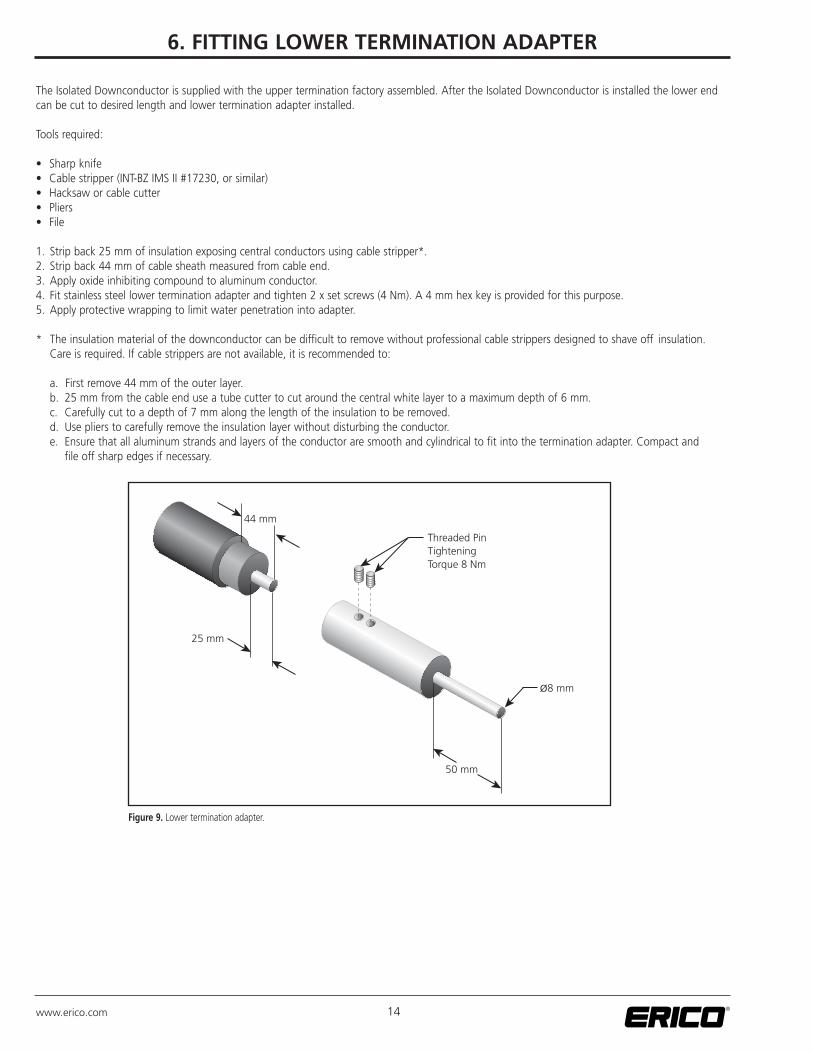
The Isolated Downconductor is supplied with the upper termination factory assembled. After the Isolated Downconductor is installed the lower endcan be cut to desired length and lower termination adapter installed.
Tools required:
• Sharp knife• Cable stripper (INT-BZ IMS II #17230, or similar)• Hacksaw or cable cutter• Pliers• File
1. Strip back 25 mm of insulation exposing central conductors using cable stripper*.2. Strip back 44 mm of cable sheath measured from cable end.3. Apply oxide inhibiting compound to aluminum conductor.4. Fit stainless steel lower termination adapter and tighten 2 x set screws (4 Nm). A 4 mm hex key is provided for this purpose.5. Apply protective wrapping to limit water penetration into adapter.
* The insulation material of the downconductor can be difficult to remove without professional cable strippers designed to shave off insulation. Care is required. If cable strippers are not available, it is recommended to:
a. First remove 44 mm of the outer layer.b. 25 mm from the cable end use a tube cutter to cut around the central white layer to a maximum depth of 6 mm.c. Carefully cut to a depth of 7 mm along the length of the insulation to be removed. d. Use pliers to carefully remove the insulation layer without disturbing the conductor.e. Ensure that all aluminum strands and layers of the conductor are smooth and cylindrical to fit into the termination adapter. Compact and
file off sharp edges if necessary.
25 mm
50 mm
ø8 mm
Threaded PinTighteningTorque 8 Nm
44 mm
Figure 9. Lower termination adapter.
6. FITTING LOWER TERMINATION ADAPTER
www.erico.com
15www.erico.com
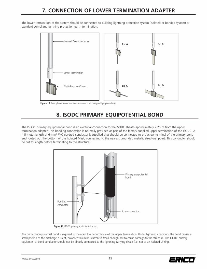
The lower termination of the system should be connected to building lightning protection system (isolated or bonded system) orstandard compliant lightning protection earth termination.
Isolated Downconductor
Lower Termination
Multi-Purpose Clamp
Figure 10. Examples of lower termination connections using multipurpose clamp.
Ex. A Ex. B
Ex. C Ex. D
7. CONNECTION OF LOWER TERMINATION ADAPTER
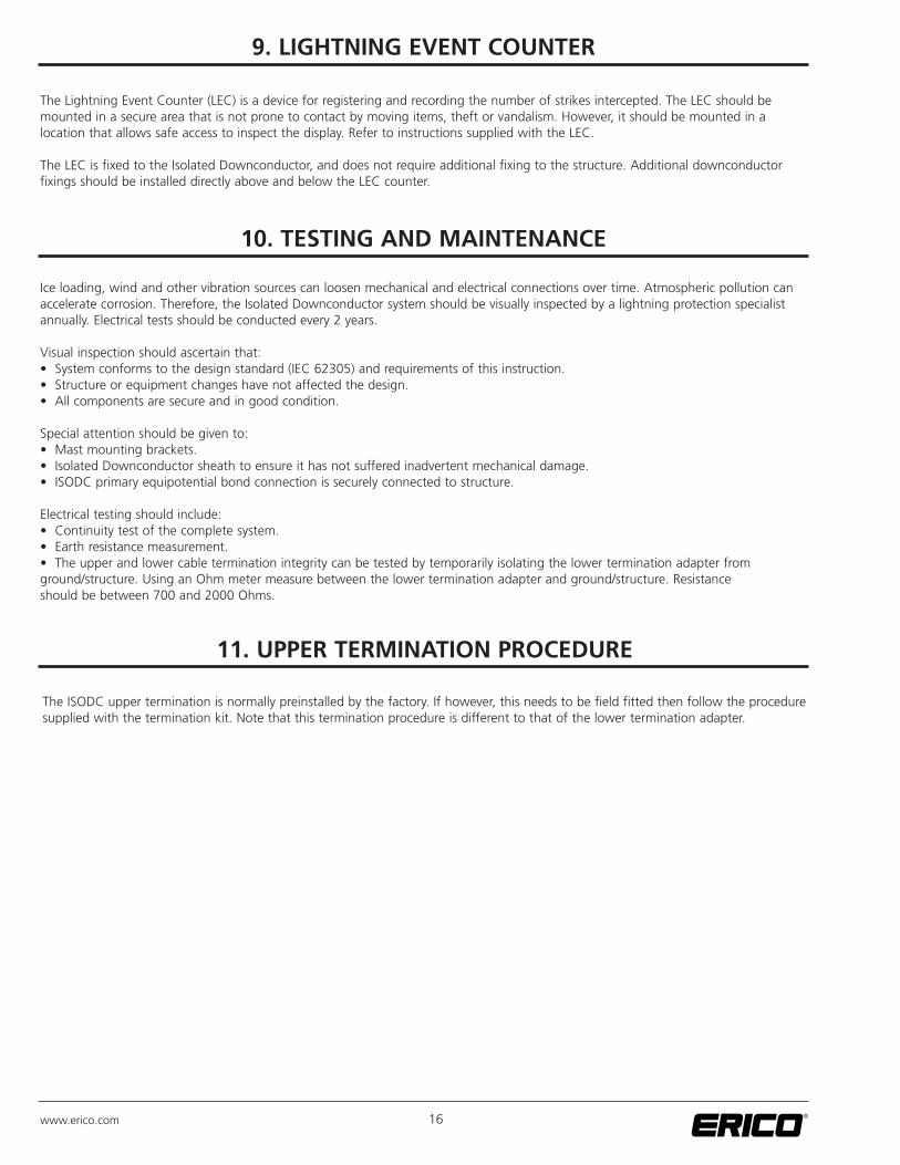
The ISODC primary equipotential bond is an electrical connection to the ISODC sheath approximately 2.25 m from the upper termination adapter. This bonding connection is normally provided as part of the factory supplied upper termination of the ISODC. A4.5 meter length of 6 mm2 PVC covered conductor is supplied that should be connected to the screw terminal of the primary bondand routed out the bottom of the Isolated Mast, connecting to the nearest grounded metallic structural point. This conductor shouldbe cut to length before terminating to the structure.
Bondingconductor
Screw connector
Primary equipotentialbond
Figure 11. ISODC primary equipotential bond.
The primary equipotential bond is required to maintain the performance of the upper termination. Under lightning conditions the bond carries asmall portion of the discharge current, however this minor current is small enough not to cause damage to the structure. The ISODC primary equipotential bond conductor should not be directly connected to the lightning carrying circuit (i.e. not to an isolated LP ring).
8. ISODC PRIMARY EQUIPOTENTIAL BOND
16www.erico.com
The Lightning Event Counter (LEC) is a device for registering and recording the number of strikes intercepted. The LEC should bemounted in a secure area that is not prone to contact by moving items, theft or vandalism. However, it should be mounted in a location that allows safe access to inspect the display. Refer to instructions supplied with the LEC.
The LEC is fixed to the Isolated Downconductor, and does not require additional fixing to the structure. Additional downconductor fixings should be installed directly above and below the LEC counter.
10. TESTING AND MAINTENANCE
Ice loading, wind and other vibration sources can loosen mechanical and electrical connections over time. Atmospheric pollution canaccelerate corrosion. Therefore, the Isolated Downconductor system should be visually inspected by a lightning protection specialistannually. Electrical tests should be conducted every 2 years.
Visual inspection should ascertain that:• System conforms to the design standard (IEC 62305) and requirements of this instruction.• Structure or equipment changes have not affected the design.• All components are secure and in good condition.
Special attention should be given to:• Mast mounting brackets.• Isolated Downconductor sheath to ensure it has not suffered inadvertent mechanical damage.• ISODC primary equipotential bond connection is securely connected to structure.
Electrical testing should include:• Continuity test of the complete system.• Earth resistance measurement.• The upper and lower cable termination integrity can be tested by temporarily isolating the lower termination adapter from ground/structure. Using an Ohm meter measure between the lower termination adapter and ground/structure. Resistance should be between 700 and 2000 Ohms.
11. UPPER TERMINATION PROCEDURE
The ISODC upper termination is normally preinstalled by the factory. If however, this needs to be field fitted then follow the proceduresupplied with the termination kit. Note that this termination procedure is different to that of the lower termination adapter.
9. LIGHTNING EVENT COUNTER

17www.erico.com
Isolated Downconductor ISODC (#701130)
Description XLPE/PE Isolated Cable
Equivalent separation distance 1000 mm of air
Material Multi-strand aluminum (19 x 1.87 mm dia.). Total cross sectional area 50 mm2
Color Black
Outer diameter 27 mm
Minimum bending radius 450 mm
Weight 0.58 kg/m
Installation temperature > 0 deg C
Operating temperature -40 deg C to 70 deg C
Termination AdaptersStainless steel 304.Lower adapter provides 8 mm diameter, 50 mm stud
StandardsIEC 62305-3EN 50164-2UL® 96A
Air Terminal AAR1015 (#711070) 1.0 m or AAR0515 (#711020) 0.5 m
Description Aluminum air terminal, safety tipped
Dimension 16 mm thread, 0.5 or 1.0 m length
Standards IEC 62305-3, EN 50164-2, UL 96A
Isolated Mast ISOFRP3M (#701140)
Description Fiberglass-reinforced thermoset polyester tube (UV stable)
Color Grey
Diameter 50 mm
Weight 4.2 kg
System
Worst case total system weight< 16 kg (Based on 3 m Isolated Mast, air terminal, 10 m of Isolated Downconductor and 2 x ALOF1GS mounting brackets).
Wind loadingISOFRP mast withstand speed > 195 km/h. Wind loading on support mast under such conditions 120 kg
12. GENERAL SPECIFICATIONS
18www.erico.com
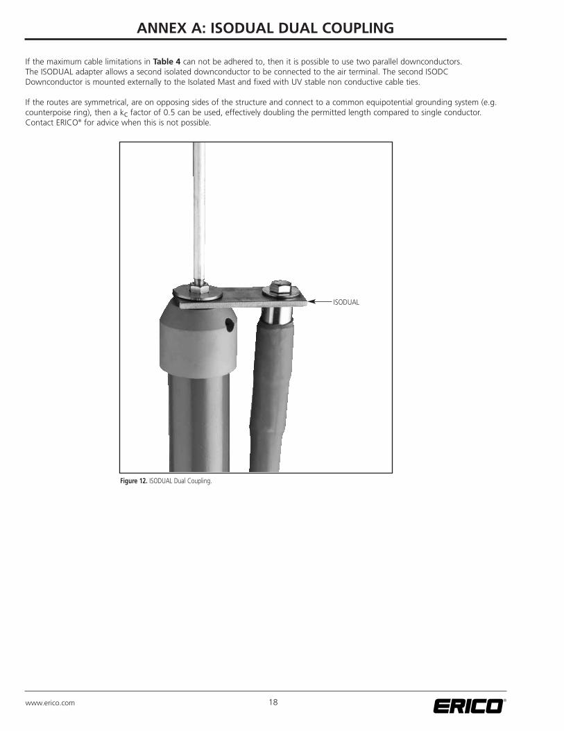
If the maximum cable limitations in Table 4 can not be adhered to, then it is possible to use two parallel downconductors. The ISODUAL adapter allows a second isolated downconductor to be connected to the air terminal. The second ISODCDownconductor is mounted externally to the Isolated Mast and fixed with UV stable non conductive cable ties.
If the routes are symmetrical, are on opposing sides of the structure and connect to a common equipotential grounding system (e.g.counterpoise ring), then a kc factor of 0.5 can be used, effectively doubling the permitted length compared to single conductor.Contact ERICO® for advice when this is not possible.
Figure 12. ISODUAL Dual Coupling.
ANNEX A: ISODUAL DUAL COUPLING
ISODUAL

19www.erico.com
Figure 13. ISOCAP68.
ANNEX B: ERITECH® SYSTEM 3000 MAST AND SUPPORT HARDWARE
4.6 m FRP Mast
ISOCAP68, Air Terminaland ISODC
Table 6. Cantilever Distance.
MAST Cantilever Distance # Mast Brackets
ALUM3M (3m) 1 m 3
ALUM4M (4m) 1 m 3
ALUM5M (5m) 1.5 m 3
ALUM6M (6m) 2 m 5
Table 7. Guy Kit.
MAST Guy Kit
MBMAST3M (3m) GUYKIT4MGRIP
MBMAST4M (4m) GUYKIT4MGRIP
MBMAST5M (5m) GUYKIT7MGRIP
MBMAST6M (6m) GUYKIT7MGRIP
3x Mast Bracket
1.5 m 1.5 m
Ø 70-75 mm Mast
ISOCAP68, Air Terminaland ISODC
2 m FRP Mast
Inline CouplingGuy Kit(See Table 7)
Aluminum Mast3-6 m (See Table 6)
Mast Brackets
Cantilever Distance(See Table 6)
Aluminum Mastwith Base 3-6 m(See Table 7)
2x U Bolt

E635I E1258IS06ENWW 003MFG7
AUSTRALIA6 Chilvers RoadP.O. Box 148Thornleigh (Sydney) NSW 2120 AustraliaPhone 61-2-9479-8500Fax 61-2-9484-9188
BELGIUMPostbus 333110 RotselaarBelgiumPhone 32-14-69-96-88Fax 32-14-69-96-90
CANADAP.O. Box 170Mississauga, OntarioCanada L5M 2B8Phone 1-800-677-9089Fax 1-800-677-8131
CHILEAlcantara 200, piso 6 Of. 17Las Condes, SantiagoChilePhone 56-2-370-2908Fax 56-2-370-2914
CHINARoom 1204 Tomson Commercial BuildingNo. 710 Dongfang RoadPudong, ShanghaiP.R. China 200122Phone 86-21-5081-3900Fax 86-21-5831-8177
DENMARKBox 211201 22 Malmö SwedenPhone 46-40-611-13-60Fax 46-40-611-94-15
FRANCErue Charles Dallière, BP 3142161 Andrezieux Bouthéon CedexFrancePhone 33-4-77-36-54-32Fax 33-4-77-55-20-10
GERMANYPostfach 114767709 Waldfischbach-BurgalbenGermanyPhone 0-800-189-0272Fax 0-800-189-0274
HONG KONGUnit 1, 2nd Floor, Block APo Yip Building62-70 Texaco Road Tsuen Wan, New TerritoriesHong KongPhone 852-2764-8808Fax 852-2764-4486
HUNGARYP.f. 1841476 BudapestHungaryPhone 31-13-58-34-547Fax 31-13-58-35-499
INDONESIASampoerna Strategic Square, Tower B 19th Fl.Jalan Jend. Sudirman Kav. 45-46Jakarta 12930IndonesiaPhone 62-21-575-0941Fax 62-21-575-0942
ITALYA&B Business CenterVia Valla 16, nr. 1720141 MilanoItalyPhone 39-02-8474-2250Fax 39-02-8474-2251
MEXICOMelchor Ocampo 193 Torre A piso 13 Col. Veronica Anzures11300 Mexico D.F.MexicoPhone 52-55-5260-5991Fax 52-55-5260-3310
NETHERLANDSJules Verneweg 755015 BG TilburgNetherlandsPhone 31-13-58-35-400Fax 31-13-58-35-499
POLANDul. Krzemieniecka 1754-613 WroclawPolandPhone 48-71-374-40-22Fax 48-71-374-40-43
SINGAPOREJurong Industrial Estate16 Wan Lee RoadSingapore 627 946Phone 65-6-268-3433Fax 65-6-268-1389
SPAINC/Provenza 288, Pral.08008 BarcelonaSpainPhone 34-93-467-7726Fax 34-93-467-7725
SWEDENBox 211201 22 MalmöSwedenPhone 46-40-611-13-60Fax 46-40-611-94-15
SWITZERLANDPostfach 543280 MurtenSwitzerlandPhone 00-800-5000-1090Fax 00-800-6000-1090
UNITED KINGDOM52 Milford RoadReading, Berkshire RG1 8LJUnited KingdomPhone 44-118-955-0900Fax 44-118-955-0925
UNITED STATES34600 Solon RoadSolon, Ohio 44139U.S.A.Phone 1-440-248-0100Fax 1-440-248-0723
NORWAYPostboks 1481366 LysakerNorwayPhone 47-67-53-12-00Fax 47-67-12-42-68
BRAZILR. Dom Pedro Henrique de OrleansE Braganca, 276Vila Jaguara São Paulo CEP 05117-000BrazilPhone 55-11-3621-4111Fax 55-11-3621-4066
THAILANDNo. 92/52 Sathorn Thani Tower 218th Floor, Room #1804North Sathorn RoadSilom, Bangrak, Bangkok 10500ThailandPhone 66-2-267-5776, 5777Fax 66-2-636-6988
www.erico.com
Copyright ©2007 ERICO International Corporation. All rights reserved.CADDY, CADWELD, CRITEC, ERICO, ERIFLEX, ERITECH, and LENTON are registered trademarks of ERICO International Corporation.
Loctite is a registered trademark of the Henkel Corporation.UL is a registered trademark of Underwriters Laboratories.