study of lightning, surge protection, earthing for s&t
TRANSCRIPT
Study of Lightning, Surge Protection, Earthing for
S&T Installations
Bhuvnesh Kumar Agrawal,CSE-II, Secunderabad, S C Railway
1 Objective
Study the Specifications, Instructions already avail-able on the subject of Lightening and SurgeProtections on Indian Railways, Study of thenon-compliance/deviations from critical instruc-tions/specifications leading to failures. Study andsuggest further improvements in consultation withOEMs. Case study of HASANPARTY station of SCdivision of SC Railway for possible reasons for recentfailures due to Bad Weather and Lightning.
2 Scope
� Need for Lightning and Surge Protections
� Sources of Transients and Surges
� Components of Protection Systems
� RDSO and Railway Instructions and Technical
� Effective Protection Plan and Components. Ad-visory Notes
� Provisions in RDSO Specifications
� Maintenance Hand books issued by CAM Tech
� Typical and Integrated Earthing and BondingPlan
� Common Deficiencies in S&T Installations
� Case Study of Hasanparty Station.
3 Need for Lightning andSurge Protection Systems
� To Protect Equipment’s against build up of HighVoltages and subsequent Damage.
� To ensure Safe and Reliable working of equip-ment’s by eliminating induced voltages
� To protect the Staff/Personnel working on theequipment’s against shock
4 Effective Protection Planand Components
Any Protection Plan should be wholistic and shouldcover the following components. There should not beany differentiation between Signalling and Telecomsystems installed at a station and both should beintegrated.
� The lightening strike should be captured at apreferred point referred to as A Class ProtectionAir Terminal on Top of the Building.
� Effective Down Conductor for diverting theLightning Energy(High Built up of Voltage) tothe Ground ( Earth).
� Effective Earthing Arrangement for dissipatingthe energy so received.
� Surge Protection Devices further referred asSPDs of Class B, C, D as per RDSO specifi-cations.
� Ensure an Equipotential Earth Plane for allEquipment’s and Sub Systems.
� Bonding of individual Equipment’s to the Eq-uity Potential Earth Plane
� Protect Equipment’s from Surges and Tran-sients coming from Incoming Power Lines
� Provisions for eliminating/limiting induced volt-ages to ensure Safe and Reliable working ofequipment’s by Armoring/Screening of Cablescarrying low voltage data and Telecom circuitsand their bonding to Equipotential earth.
� The laying and drawing of wires/cables with ad-equate spacing between Clean and Dirty wiresto reduce possibility of induced voltages in cleanwires carrying vital circuits due to transients inDirty wires.
� To minimize the effect of circulating EarthLoops

5 A Class Protection Systems
As per extant instructions from Railway Boardand RDSO A class LPS are to be provided for allElectronic Interlocking Installations of the type ofFranklin Rod of 3 meters height (TAN 3006) forprotection against direct lightning strikes.
There are three primary components of the A Classsystems shown in Figure 1.
� Air Terminal
� Down Conductor
� Earth Grounding System
Figure 1:
The Air terminal captures the lightning dischargecurrent which is dissipated to Earth through Downconductor.
The Protection area is normally calculated basedon Rolling Sphere Method as seen in Figure 2 As perIEC standards an angle of 45 degrees is considered asstandard zone of protection. Accordingly, the num-ber of Air Terminals shall be planned.
Figure 2:
The Down conductor is a copper cable of adequatesize. 50% of the lightning energy is transferred tothe ground.
It is seen that there are no standards specified fordesign, type of Air Terminals and Down Conductorby RDSO. Railways are using the practices assuggested by OEMs.
It is recommended that RDSO shall clearlyspecify the complete Design, Types, Material,Protection Coverage for Air Terminals andDown Conductor through separate Specifi-cations to have uniformity and control overquality in installations.
The Earth and Grounding Systems are well cov-ered in RDSO Specifications 197/2008. The impor-tant considerations are covered in para 7 of this re-port.
6 Class B & C Stage 1 andStage 2 Protection SystemsSPDs
As per RDSO/SPN/165/2012 Class B& C SPDsStage 1 are required to be provided at the 230 Inputlevel in TT Configuration. The class B are of SparkGap type Voltage Switching Device tested as perIEC 61643. Similarly, Class C SPD to be providedbetween Line and Neutral which is a single compactvaristor, a voltage clamping device and thermaldisconnection type. Also, Class C SPDs Stage 2 areprovided on the output side for external circuits.
AS per specs the provisions of End-of-Life Indi-cation and Potential Free Contacts are cateredas below.
For SPD Class B between Line and Neutral
� End of Life Indication: Mandatory
� Potential Free Contact: Optional
For SPD Class B between Neutral and Earth
� End of Life Indication: Optional
� Potential Free Contact: Optional
For SPD Class C between Line and Neutral
� End of Life Indication: Mandatory

� Potential Free Contact: Mandatory
It is seen that recently approved specifications byRDSO/SPN/215/2018 issue Date 11.02.2018 forIPS under the title “Power Supply ArrangementLevel Crossing Gates/Intermediate Block Work-ing/Intermediate Relay Hut” above features havebeen made Mandatory for both Class B & C.
It is suggested that the same should bemade Mandatory for IPS SpecificationsRDSO/SPN/165/2012. This will provideopportunity of Prewarning for replacementof a failed SPD.
It was seen at MLYC station that the poten-tial free contacts provided are not accessiblefor further wiring due to very close interspac-ing of SPDs Fig 3. It is recommended thatthe PF contacts should be prewired and madeavailable on a row of terminals which can beeasily accessed and wired to Data loggers.
Figure 3:
Another common deficiency/non-compliance of avery important provision of these specs, which isalso covered under Earthing specs, TANs, Boardletters is normally seen at installations i.e. “MEEB(Main Earth Equipotential Busbar) shall beinstalled at 20 Cms to SPD with Connectingcable length being less than 0.5 Meters with-out any Bends.”
Location of SPD Box: It is also recommendedthat the SPD box should be so located on thewall such that there is no cable ladder aboveit to avoid any incidence of cables on ladderburning due to any malfunctioning of SPDscausing fire. The author has been witness toone such incidence at Mantralayam station ofGTL division causing total shutdown of thePanel.
7 Earthing and EquipotentialEarthing and Bonding Plan
I would like to give a substantial weightage to thisMOST VITAL part of the entire Eco System ofLightening, Surge and Transients Protection Plan asmost of the issues here pertain to installation de-ficiencies due to unawareness of executing agenciesand maintenance officials coupled with use of poorquality of materials/workmanship.
7.1 Location of Earth Electrodes
� The earth electrodes should be preferably lo-cated in mother soil and not high banks, made-up soil. The distance between two earth elec-trodes shall be maintained at 3 to 6 meters.
� Normally it is desired that the earth electrodesshould be provided on either side of the build-ing for Perimetric Earth. To achieve this careand coordination should happen at the stageof building construction for providing GI Pipesacross the building at specified locations (samewill be explained more clearly in a TypicalEarthing Plan). In case it is not possible to havea Perimetric Earthing a Ring Earth should beprovided on one side of the building for whichadequate non-Concrete surface should be en-sured to achieve 3 to 6 meters spacing betweenearth electrodes.
� It should be insisted upon and provided for whileapproving the Building Drawing that a provisionof Plinth area of 1.5 Meters on both sides ofthe building shall not be concreted to cater forprovision of earth electrodes.
7.2 Choice of Type of Earth Elec-trodes
� Conventional Electrode of GI Pipe
� MF Earth Electrode made up of high tensile lowcarbon steel rod with copper coating on outersurface.
Irrespective above choices, the earth values realizedwill normally be function of soil resistivity, howeverit is preferred that for all Earths in station areashould be of MF type simply because of beingalmost maintenance free and providing lastingconnections through exothermic welding. Theconventional GI Pipe electrodes are prone to rusting
and deterioration over a period of time.
For outdoor application MF earths are preferredfor DAC application since required earth values are¡1 ohms, for others in outdoor Conventional elec-trodes can be used, however it needs regular mainte-nance/replacement.
7.3 Provision of Loop earths andRing/Perimetric Earth arrange-ments
� Additional Earth electrodes should be providedat 3 to 6 meters spacing and looped/interlinkedwith copper tapes and exothermically welded
� The copper tapes shall be laid at a depth of 0.5meters
� This copper tape should also be covered withearth enhancing compound
� Whenever the distance between an EquipmentRoom in the same building or a separate build-ing is more than 25 Meters, there should be aseparate Earthing System.
7.4 Concept of MEEB (Main Equipo-tential Earth Busbar) and SEEB(Sub Equipotential Earth Bus-bar) and BRC (Bonding RingPerimetric)
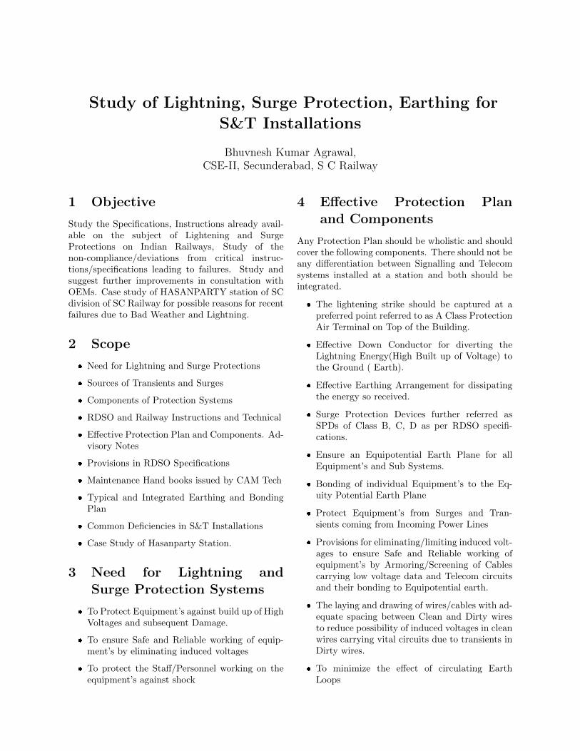
� As can be seen in Figure 4 Typical Earthingand Bonding Plan There is a Perimetric RingEarth with six Electrodes covering the Equip-ment (IPS) Room and Relay Room of which Oneelectrode is termed a main electrode.
� It can be seen that two Perimetric earthing sys-tems are considered for Signalling and Telecominstallations with interconnection for achievingEquipotential Earth
� The number of Earth electrodes can be decidedbased on-site conditions to achieve ¡1-ohm val-ues.
� Separate Earths are catered for Lightning Ar-restors, VHF Sets, Quad Cables which arefurther interlinked with Perimetric Earth toachieve equipotential Earth.
� The Main Electrode alone is connected toMEEB Copper strip in Equipment Room Justbelow the SPD Box of the IPS. As per recent
TAN, it is to be connected with 4 numbers of 35Sq mm Copper cables.
� SEEBs are provided in Each Room directlyconnected to MEEB through suitable multicorecopper cables.
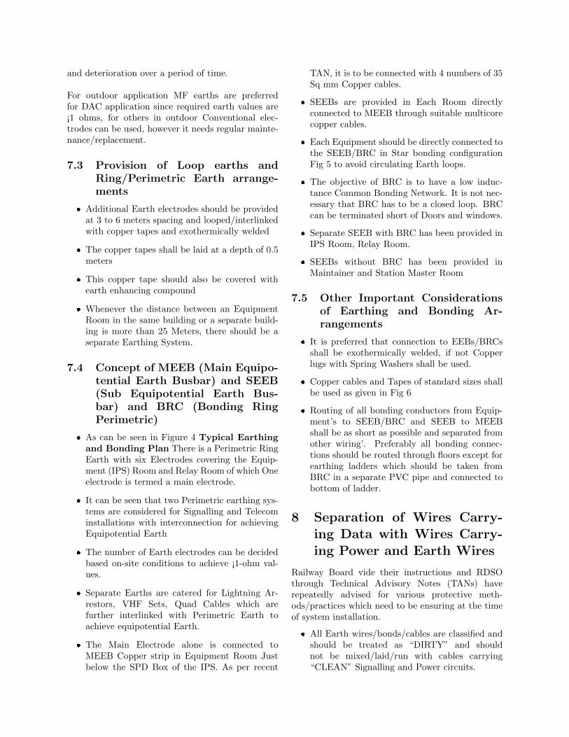
� Each Equipment should be directly connected tothe SEEB/BRC in Star bonding configurationFig 5 to avoid circulating Earth loops.
� The objective of BRC is to have a low induc-tance Common Bonding Network. It is not nec-essary that BRC has to be a closed loop. BRCcan be terminated short of Doors and windows.
� Separate SEEB with BRC has been provided inIPS Room, Relay Room.
� SEEBs without BRC has been provided inMaintainer and Station Master Room
7.5 Other Important Considerationsof Earthing and Bonding Ar-rangements
� It is preferred that connection to EEBs/BRCsshall be exothermically welded, if not Copperlugs with Spring Washers shall be used.
� Copper cables and Tapes of standard sizes shallbe used as given in Fig 6
� Routing of all bonding conductors from Equip-ment’s to SEEB/BRC and SEEB to MEEBshall be as short as possible and separated fromother wiring’. Preferably all bonding connec-tions should be routed through floors except forearthing ladders which should be taken fromBRC in a separate PVC pipe and connected tobottom of ladder.
8 Separation of Wires Carry-ing Data with Wires Carry-ing Power and Earth Wires
Railway Board vide their instructions and RDSOthrough Technical Advisory Notes (TANs) haverepeatedly advised for various protective meth-ods/practices which need to be ensuring at the timeof system installation.
� All Earth wires/bonds/cables are classified andshould be treated as “DIRTY” and shouldnot be mixed/laid/run with cables carrying“CLEAN” Signalling and Power circuits.
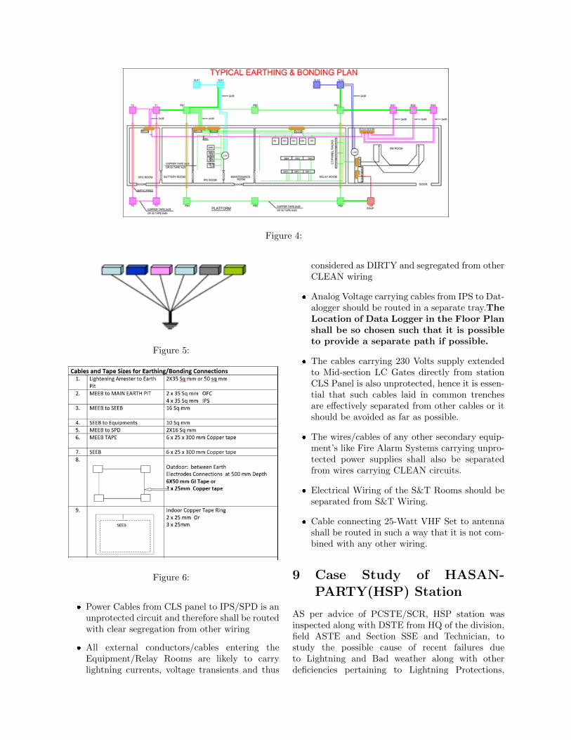
Figure 4:
Figure 5:
Figure 6:
� Power Cables from CLS panel to IPS/SPD is anunprotected circuit and therefore shall be routedwith clear segregation from other wiring
� All external conductors/cables entering theEquipment/Relay Rooms are likely to carrylightning currents, voltage transients and thus
considered as DIRTY and segregated from otherCLEAN wiring
� Analog Voltage carrying cables from IPS to Dat-alogger should be routed in a separate tray.TheLocation of Data Logger in the Floor Planshall be so chosen such that it is possibleto provide a separate path if possible.
� The cables carrying 230 Volts supply extendedto Mid-section LC Gates directly from stationCLS Panel is also unprotected, hence it is essen-tial that such cables laid in common trenchesare effectively separated from other cables or itshould be avoided as far as possible.
� The wires/cables of any other secondary equip-ment’s like Fire Alarm Systems carrying unpro-tected power supplies shall also be separatedfrom wires carrying CLEAN circuits.
� Electrical Wiring of the S&T Rooms should beseparated from S&T Wiring.
� Cable connecting 25-Watt VHF Set to antennashall be routed in such a way that it is not com-bined with any other wiring.
9 Case Study of HASAN-PARTY(HSP) Station
AS per advice of PCSTE/SCR, HSP station wasinspected along with DSTE from HQ of the division,field ASTE and Section SSE and Technician, tostudy the possible cause of recent failures dueto Lightning and Bad weather along with otherdeficiencies pertaining to Lightning Protections,

SPDs, Earthing arrangements.
It was seen that the following failures had occurredin recent past
� Outgoing TPR 24 V DC fuses at same locationbox were fused for Track Circuits 29T, 11T, 39T
� DN East Line HASSDAC failed and Mother-board burnt
� RE Cutting 24 Volts DC Signal circuit Fuseblown at Relay Rack. It is a mid-section LCGate with IPS. Same also used for RE cuttingpurpose.
9.1 Track Circuits failure
� The power cable carrying 24 V DC from Cabinto Location box was checked and properlyearthed
� Signalling cable carrying TPR circuits was prop-erly earthed at Cabin end and cable was meg-gered and values above 100 M ohms.
� The 24 V DC output at IPS was protected withSPD found in working condition
� At the Location box, it was seen that the powercable 24V DC armour earthing at GI wire wasloose and not soldered. Further GI wire was alsorusted Fig 7
Figure 7:
The probable cause of fuse blowing is due toineffective earthing of the power cable armourat location end.
9.2 HASSDAC failure
� � It was seen that the 24 V DC to HASSDACwas extended from an External DC-DC conver-tor unit (Not from the IPS Modules) which wasnot protected by SPD Fig 8.
Figure 8:
� The location end Earthing and armour connec-tivity was found intact.
� The possibility of surge coming through Quadcable could not be checked as the system waschanged to new quad cable laid by constructiontwo days before our visit.
� It was seen that the HASSDAC motherboardwas burnt at the power supply cards area
It was also seen that the West Line HASS-DAC supply was extended from DC-DC con-vertor modules of IPS protected with SPDshence it was not failing, Only East Line HAS-SDAC was regularly failing. The probablecause was non protection of external supplywith SPD.
9.3 RE Cutting Failure
� The RE Cutting for Distant Signal is providedat the Relay Room of a Mid-section LC gate

having its own mini IPS.
� The IPS provided is as per 2004 specificationswith external supplies protected by MOVs andnot SPDs.
� RDSO vide its letter No STS/E/IPS. GenlDated 02.12.2011 had advised Railways for mod-ification by OEMs for provision of SPDs for allexternal supplies at pre-specified Rates. It is no-ticed that the required modifications were notcarried out in this IPS.
� The Earth Value at IPS MEEB was found 3Ohms which is on higher side.
The probable cause of failure was non-protection of 24 V DC external supply by SPDand high earth resistance.
9.4 Other deficiencies noticed at HSPstation
� In both Cabins the MEEB at IPS Room and Re-lay Room were two separate earths without anyinterconnection i.e. not having an equipotentialearth.
� The MEEB for IPS was located in BatteryRoom and connected to SPD of IPS with a ca-ble length of 10 to 15 Meters and size 10 sq mmand mixed on ladder with other wiring
� The 230 Supply Power cable from CLS panel toIPS was mixed with other wiring and laid on acommon ladder.
� A single Earth was provided for both side Quadcables without interconnection to Ring Earth
� The BPAC and Block circuits were changed overto new quad cable without any earthing of quadarmour at other end station KMPT resulting inhigh induced voltage of 54 Volts.
� The quad pairs were not twisted before termi-nations at either ends.
� Many of the outdoor Earths to location Boxesand Signals were hugely rusted and connectedwith GI wires.
10 Recommendations for Im-provement
10.1 The Conventional Earth Elec-trode
� It is normally seen that the conventional earthelectrodes, though supplied with RITES inspec-tion, over a short period of time gets rusted.Specially the bracket to which earth Cable/GIWire/MS Flat are connected. Same can be seenin figures 9 to 10. Stricter quality checks are re-quired at Inspection Points such that the poorquality materials are rejected.
Figure 9:
Figure 10:
� It is recommended to change the design ofbracket to double brackets as shown in Fig 12
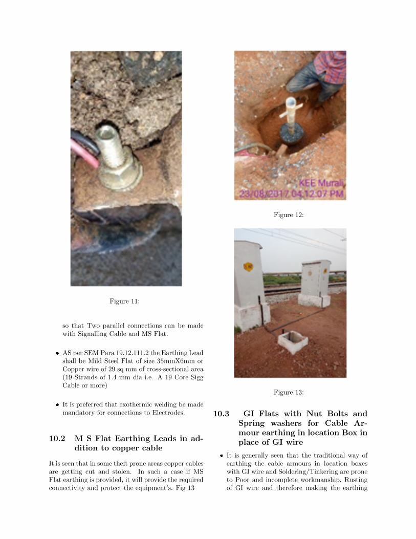
Figure 11:
so that Two parallel connections can be madewith Signalling Cable and MS Flat.
� AS per SEM Para 19.12.111.2 the Earthing Leadshall be Mild Steel Flat of size 35mmX6mm orCopper wire of 29 sq mm of cross-sectional area(19 Strands of 1.4 mm dia i.e. A 19 Core SiggCable or more)
� It is preferred that exothermic welding be mademandatory for connections to Electrodes.
10.2 M S Flat Earthing Leads in ad-dition to copper cable
It is seen that in some theft prone areas copper cablesare getting cut and stolen. In such a case if MSFlat earthing is provided, it will provide the requiredconnectivity and protect the equipment’s. Fig 13
Figure 12:
Figure 13:
10.3 GI Flats with Nut Bolts andSpring washers for Cable Ar-mour earthing in location Box inplace of GI wire
� It is generally seen that the traditional way ofearthing the cable armours in location boxeswith GI wire and Soldering/Tinkering are proneto Poor and incomplete workmanship, Rustingof GI wire and therefore making the earthing

ineffective inspite of the earth electrode havinggood earth value. The same was witnessed atHSP station causing fuse blowing.
� AS can be seen in the figure 14 The GI flats aredrilled with adequate holes for connecting thearmours of all possible cables in the location boxbesides having a cushion for future connections.The use of sring washers ensures firm and lastingconnection.
Figure 14:
11 Use of advanced SPDs andA Class Protection Systems
With Constant research and innovation, companiesare coming up with innovative solutions and con-stantly improving on their products. However, theefficiency and effectiveness of such advanced SPDscan only be ascertained over a period of reasonableservice and availability of empirical data. Consider-ing the Cost implications, it is suggested to use themat few Most Lighting Prone Zones. As per IEC thereare different classes of environment.
11.1 Transient Discriminating Tech-nology SPDs by ERICO
In a conventional SPD using MOVs or SiliconAvalanche Diodes are not able to differentiatebetween a sustained Temporary Over Voltage and atrue Transient or Surge event thus tend to suppresspeak of each Half Cycle of the TOV, causing heatingup of device which can potentially lead to fire hazardas shown in Fig. . .
While TD technology SPDs have a patented QuickSwitch with frequency discrimination circuit whichcan differentiate between TOVs and fast transientsassociated with Lightnings Strikes/Surges. The de-vice has two clamping levels, one above peak of TOVwhich normally is twice the nominal voltage and
Figure 15:
other much lower for transients. It therefore en-hances operational life of the SPD. Fig 16
Figure 16:
11.2 A Class Protection Systems
Currently we are using two types of A class systemson Indian Railways
� Conventions Franklin Rod air terminal Fig 17
� Advanced Controlled Streamer Emission (CSE)Based air terminal Fig 18
There are three primary components of the A Classsystems
� Air Terminal
� Down Conductor
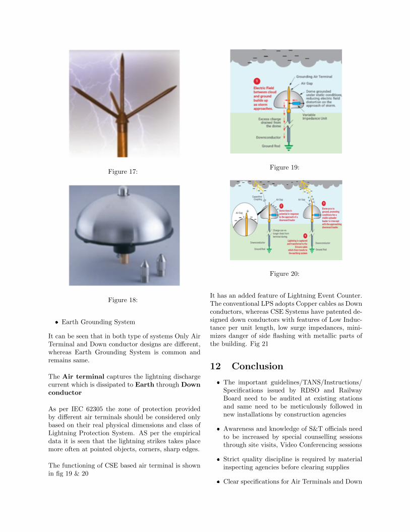
Figure 17:
Figure 18:
� Earth Grounding System
It can be seen that in both type of systems Only AirTerminal and Down conductor designs are different,whereas Earth Grounding System is common andremains same.
The Air terminal captures the lightning dischargecurrent which is dissipated to Earth through Downconductor
As per IEC 62305 the zone of protection providedby different air terminals should be considered onlybased on their real physical dimensions and class ofLightning Protection System. AS per the empiricaldata it is seen that the lightning strikes takes placemore often at pointed objects, corners, sharp edges.
The functioning of CSE based air terminal is shownin fig 19 & 20
Figure 19:
Figure 20:
It has an added feature of Lightning Event Counter.The conventional LPS adopts Copper cables as Downconductors, whereas CSE Systems have patented de-signed down conductors with features of Low Induc-tance per unit length, low surge impedances, mini-mizes danger of side flashing with metallic parts ofthe building. Fig 21
12 Conclusion
� The important guidelines/TANS/Instructions/Specifications issued by RDSO and RailwayBoard need to be audited at existing stationsand same need to be meticulously followed innew installations by construction agencies
� Awareness and knowledge of S&T officials needto be increased by special counselling sessionsthrough site visits, Video Conferencing sessions
� Strict quality discipline is required by materialinspecting agencies before clearing supplies
� Clear specifications for Air Terminals and Down
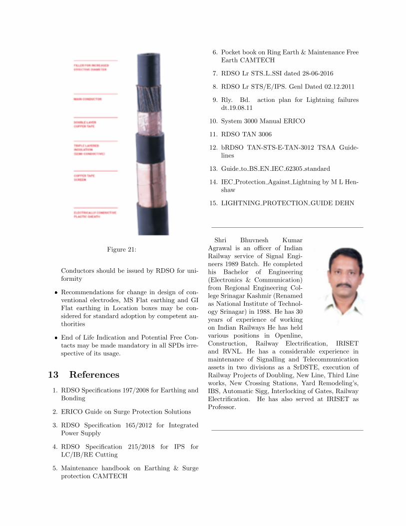
Figure 21:
Conductors should be issued by RDSO for uni-formity
� Recommendations for change in design of con-ventional electrodes, MS Flat earthing and GIFlat earthing in Location boxes may be con-sidered for standard adoption by competent au-thorities
� End of Life Indication and Potential Free Con-tacts may be made mandatory in all SPDs irre-spective of its usage.
13 References
1. RDSO Specifications 197/2008 for Earthing andBonding
2. ERICO Guide on Surge Protection Solutions
3. RDSO Specification 165/2012 for IntegratedPower Supply
4. RDSO Specification 215/2018 for IPS forLC/IB/RE Cutting
5. Maintenance handbook on Earthing & Surgeprotection CAMTECH
6. Pocket book on Ring Earth & Maintenance FreeEarth CAMTECH
7. RDSO Lr STS L SSI dated 28-06-2016
8. RDSO Lr STS/E/IPS. Genl Dated 02.12.2011
9. Rly. Bd. action plan for Lightning failuresdt.19.08.11
10. System 3000 Manual ERICO
11. RDSO TAN 3006
12. bRDSO TAN-STS-E-TAN-3012 TSAA Guide-lines
13. Guide to BS EN IEC 62305 standard
14. IEC Protection Against Lightning by M L Hen-shaw
15. LIGHTNING PROTECTION GUIDE DEHN
Shri Bhuvnesh KumarAgrawal is an officer of IndianRailway service of Signal Engi-neers 1989 Batch. He completedhis Bachelor of Engineering(Electronics & Communication)from Regional Engineering Col-lege Srinagar Kashmir (Renamedas National Institute of Technol-ogy Srinagar) in 1988. He has 30years of experience of workingon Indian Railways He has heldvarious positions in Openline,Construction, Railway Electrification, IRISETand RVNL. He has a considerable experience inmaintenance of Signalling and Telecommunicationassets in two divisions as a SrDSTE, execution ofRailway Projects of Doubling, New Line, Third Lineworks, New Crossing Stations, Yard Remodeling’s,IBS, Automatic Sigg, Interlocking of Gates, RailwayElectrification. He has also served at IRISET asProfessor.