instruction manual for residential gas water heaters
TRANSCRIPT
ALL TECHNICAL AND WARRANTY QUESTIONS: SHOULD BE DIRECTED TO THE LOCAL DEALER FROMWHOM THE WATER HEATER WAS PURCHASED. IF YOU ARE UNSUCCESSFUL, PLEASE WRITE TO THECOMPANY LISTED ON THE RATING PLATE ON THE WATER HEATER.
GAMA certification applies to allresidential gas water heaters withcapacities of 20 to 100 gallonswith input rating of 75,000BTU/Hr. or less.
–Do not store or use gasoline or otherflammable vapors and liquids in the vicinityof this or any other appliance.
–WHAT TO DO IF YOU SMELL GAS• Do not try to light any appliance.• Do not touch any electrical switch; do not
use any phone in your building.• Immediately call your gas supplier from a
neighbor’s phone. Follow the gas suppli-er’s instructions.
• If you cannot reach your gas supplier, callthe fire department.
–Installation and service must be performedby a qualified installer, service agency orthe gas supplier.
WARNING: If the information in theseinstructions are not followed exactly, a fireor explosion may result, causing propertydamage, personal injury or death.
Improper installation, adjustment, alteration,service or maintenance can cause DEATH,SERIOUS BODILY INJURY, OR PROPERTYDAMAGE. Refer to this manual for assistanceor consult the local gas utility for furtherinformation.
WARNING
Flammable vapors may be drawn by air cur-rents from other areas of the structure to thisappliance.
WARNING
READ THE GENERAL SAFETY SECTIONBEGINNING ON INSIDE COVER AND THENTHIS ENTIRE MANUAL BEFORE INSTALLINGOR OPERATING THIS WATER HEATER.
WARNING
Save this Manual for Future Reference.
For Your Safety AN ODORANT IS ADDED TO THE GASUSED BY THIS WATER HEATER
Instruction Manual for Residential Gas Water HeatersNOT FOR USE IN MANUFACTURED (MOBILE) HOMES
184115-00003-03

2
WARNINGWATER HEATERS EQUIPPED FOR ONE TYPE GAS ONLY: Thiswater heater is equipped for one type gas only. Check the ratingplate near the gas control valve for the correct gas. DO NOT USETHIS WATER HEATER WITH ANY GAS OTHER THAN THE ONESHOWN ON THE MODEL RATING PLATE. Failure to use the cor-rect gas can cause problems which can result in DEATH, SERIOUSBODILY INJURY, OR PROPERTY DAMAGE. If you have any ques-tions or doubts consult your gas supplier or local utility.
WARNINGA fire can start if combustible materials such as clothing, cleaningmaterials, or flammable liquids are placed against or next to thewater heater.
WARNINGINSTALLATIONS IN AREAS WHERE FLAMMABLE LIQUIDS(VAPORS) ARE LIKELY TO BE PRESENT OR STORED (GARAGES,STORAGE, AND UTILITY AREAS, ETC): Flammable liquids (suchas gasoline, solvents, propane (LP) or butane, etc.), all of whichemit flammable vapors, may be improperly stored or used in suchareas. The gas water heater pilot light or main burner can ignitesuch vapors. The resulting flashback and fire can cause death orserious burns to anyone in the area, as well as property damage.If installation in such areas is your only option, then the installa-tion must be accomplished in a way that the pilot flame and mainburner flame are elevated from the floor at least 18 inches. Whilethis may reduce the chances of flammable vapors from a floorspill being ignited, gasoline and other flammable substancesshould never be stored or used in the same room or area contain-ing a gas water heater or other open flame or spark producingappliance. NOTE: Flammable vapors may be drawn by air currents fromother areas of the structure to the appliance.
WARNINGHOTTER WATER CAN SCALD: Water heaters are intended toproduce hot water. Water heated to a temperature which willsatisfy space heating, clothes washing, dish washing, and othersanitizing needs can scald and permanently injure you uponcontact. Some people are more likely to be permanently injuredby hot water than others. These include the elderly, children,the infirm, or physically/mentally handicapped. If anyone usinghot water in your home fits into one of these groups or if thereis a local code or state law requiring a certain temperaturewater at the hot water tap, then you must take special precau-tions. In addition to using the lowest possible temperature set-ting that satisfies your hot water needs, a means such as a mix-ing valve, shall be used at the hot water taps used by these peo-ple or at the water heater. Mixing valves are available at plumb-ing supply or hardware stores. Follow manufacturers instruc-tions for installation of the valves. Before changing the factorysetting on the thermostat, read the “Temperature Regulation”section in this manual.
WARNINGBEFORE LIGHTING PROPANE (L.P.) GAS WATER HEATERS:Propane (L.P.) gas is heavier than air. Should there be a leak inthe system, the gas will settle near the ground. Basements,crawl spaces, skirted areas under manufactured (mobile)homes (even when ventilated), closets and areas below groundlevel will serve as pockets for the accumulation of this gas.Before attempting to light or relight the water heater’s pilot orturning on a nearby electrical light switch, be absolutely surethere is no accumulated gas in the area. Search for odor of gasby sniffing at ground level in the vicinity of the appliance. Ifodor is detected, follow steps indicated at “For Your Safety” onthe cover page of this manual then leave the premises.
WARNINGImproper installation, adjustment, alteration, service or mainte-nance can cause DEATH, SERIOUS BODILY INJURY, OR PROP-ERTY DAMAGE. Refer to this manual or consult your local gasutility for assistance.
WARNINGAt the time of manufacture this water heater was provided witha combination temperature-pressure relief valve certified by anationally-recognized testing laboratory that maintains periodicinspection of production of listed equipment or materials, asmeeting the requirements for Relief Valves and Automatic GasShutoff Devices for Hot Water Supply Systems, and the currentedition of ANSI Z21.22 and the code requirements of ASME. Ifreplaced, the valve must meet the requirements of local codes,but not less than a combination temperature and pressure reliefvalve certified as meeting the requirements for Relief Valvesand Automatic Gas Shutoff Devices for Hot Water SupplySystems, ANSI Z21.22 by a nationally recognized testing labo-ratory that maintains periodic inspection of production of listedequipment or materials.The valve must be marked with a maximum set pressure not toexceed the marked hydrostatic working pressure of the waterheater (150 lbs. p.s.i.) and a discharge capacity not less thanthe water heater input rate as shown on the model ratingplate. (Electric heaters - watts divided by 1000 x 3412 equalBTU/Hr. rate.)Your local jurisdictional authority, while mandating the use of atemperature-pressure relief valve complying with ANSI Z21.22and ASME, may require a valve model different from the onefurnished with the water heater.Compliance with such local requirements must be satisfied bythe installer or end user of the water heater with a locally pre-scribed temperature-pressure relief valve installed in the desig-nated opening in the water heater in place of the factory fur-nished valve.For safe operation of the water heater, the relief valve must notbe removed from it’s designated opening or plugged.The temperature-pressure relief valve must be installed directlyinto the fitting of the water heater designated for the reliefvalve. Position the valve downward and provide tubing so thatany discharge will exit only within 6 inches above, or at anydistance below the structural floor. Be certain that no contact ismade with any live electrical part. The discharge opening mustnot be blocked or reduced in size under any circumstances.Excessive length, over 30 feet, or use of more than four elbowscan cause restriction and reduce the discharge capacity of thevalve.No valve or other obstruction is to be placed between therelief valve and the tank. Do not connect tubing directly to dis-charge drain unless a 6″ air gap is provided. To prevent bodilyinjury, hazard to life, or property damage, the relief valve mustbe allowed to discharge water in quantities should circum-stances demand. If the discharge pipe is not connected to adrain or other suitable means, the water flow may cause prop-erty damage.The Discharge Pipe:—Must not be smaller in size than the outlet pipe size of the
valve, or have any reducing couplings or other restrictions.—Must not be plugged or blocked.—Must be of material listed for hot water distribution.—Must be installed so as to allow complete drainage of both
the temperature-pressure relief valve, and the discharge pipe.—Must terminate at an adequate drain.—Must not have any valve between the relief valve and tank.
General Safety
3
WARNINGThis water heater must not be installed directly on carpeting.Carpeting must be protected by a metal or wood panel beneaththe appliance extending beyond the full width and depth of theappliance by at least 3 inches (76.2mm) in any direction, or if theappliance is installed in an alcove or closet, the entire floor mustbe covered by the panel. Failure to heed this warning may resultin a fire hazard.
WARNINGA gas water heater cannot operate properly without the correctamount of air for combustion. Do not install in a confined areasuch a closet, unless you provide air as shown in the “LocatingThe New Water Heater” section. Never obstruct the flow of ven-tilation air. If you have any doubts or questions at all, call yourgas company. Failure to provide the proper amount of combus-tion air can result in a fire or explosion and can cause DEATH,SERIOUS BODILY INJURY, OR PROPERTY DAMAGE.
WARNINGIf this water heater will be used in beauty shops, barber shops,cleaning establishments, or self-service laundries with dry clean-ing equipment, it is imperative that the water heater or waterheaters be installed so that combustion and ventilation air betaken from outside these areas. Refer to the “Locating The NewWater Heater” section of this manual and also the current edi-tion of the National Fuel Gas Code, ANSI Z223.1, also referredto as NFPA 54 for specifics provided concerning air required.
WARNINGVENT DAMPERS - Any vent damper, whether it is operated ther-mally or otherwise must be removed if its use inhibits properdrafting of the water heater.Thermally Operated Vent Dampers: Gas-fired water heaters hav-ing thermal efficiency in excess of 80% may produce a relativelylow flue gas temperature. Such temperatures may not be highenough to properly open thermally operated vent dampers. Thiswould cause spillage of flue gases and may cause carbon monox-ide poisoning.Vent dampers must bear evidence of certification as complyingwith the current edition of American National Standard ANSIZ21.68 (ANSI Z21.66 & 67, respectively, cover electrically andmechanically actuated vent dampers). Before installation of anyvent damper, consult the gas utility for further information.
WARNING1. The appliance and its individual shutoff valve must be discon-
nected from the gas supply piping system during any pressuretesting of the gas system at test pressures in excess of 1⁄2 poundper square inch (3.5kPa).
2. The appliance must be isolated from the gas supply piping sys-tem by closing its individual manual shutoff valve during anypressure testing of the gas supply piping system at test pres-sures equal or less than 1⁄2 pound per square inch (3.5kPa).
WARNINGSoot build-up indicates a problem that requires correction beforefurther use. Turn “OFF” gas to water heater and leave “OFF”until repairs are made, because failure to correct the cause of thesooting can result in a fire or explosion causing DEATH, SERI-OUS BODILY INJURY, OR PROPERTY DAMAGE.
WARNINGThe water heater with draft hood installed must be properly vent-ed to a chimney which terminates outdoors. Never operate thewater heater unless it is vented to the outdoors and has adequateair supply to avoid risks of improper operation, explosion orasphyxiation.
General SafetyWARNING
Obstructed or deteriorated vent systems may present a serioushealth risk or asphyxiation.
WARNINGChemical vapor corrosion of the flue and vent system may occur ifair for combustion contains certain chemical vapors. Spray canpropellants, cleaning solvents, refrigerator and air conditionerrefrigerants, swimming pool chemicals, calcium and sodium chlo-ride, waxes, bleach, and process chemicals are typical compoundswhich are potentially corrosive.
WARNINGMinimum clearances between the water heater and combustibleconstruction are 1″ at the sides and rear, 4″ at the front, and 6″from the vent pipe. Clearance from the top of the jacket is 18″ onmost models. Note that a lesser dimension may be allowed onsome models, refer to the label attached adjacent to the gas con-trol valve on the water heater.
WARNINGHYDROGEN GAS: Hydrogen gas can be produced in a hot watersystem that has not been used for a long period of time (generallytwo weeks or more). Hydrogen gas is extremely flammable andexplosive. To prevent the possibility of injury under these conditions,we recommend the hot water faucet be opened for several minutesat the kitchen sink before any electrical appliances which are con-nected to the hot water system are used (such as a dishwasher orwashing machine). If hydrogen gas is present, there will probably bean unusual sound similar to air escaping through the pipe as the hotwater faucet is opened. There must be no smoking or open flamenear the faucet at the time it is open.
WARNINGINSULATING JACKETS: When installing an external water heaterinsulation jacket on a gas water heater:a. DO NOT cover the temperature-pressure relief valve.b. DO NOT put insulation over any part of the top of the gas water
heater.c. DO NOT put insulation over the gas control valve or gas control
valve/burner cover, or any access areas to the burner.d. DO NOT let insulation around the gas water heater to get within
8 inches of the floor (air must get to the burner).e. DO NOT cover or remove operating instructions, and safety relat-
ed warning labels and materials affixed to the water heater.Failure to heed this will result in the possibility of a fire or explosion.
WARNINGFlood damage to a water heater may not be readily visible or imme-diately detectible. However, over a period of time a flooded waterheater will create dangerous conditions which can cause DEATH,SERIOUS BODILY INJURY, OR PROPERTY DAMAGE. Call a quali-fied service technician or contractor to replace a flooded waterheater. Do not attempt to repair the unit! It must be replaced!
CAUTIONWATER HEATERS EVENTUALLY LEAK: Installation of the waterheater must be accomplished in such a manner that if the tank orany connections should leak, the flow of water will not cause dam-age to the structure. For this reason, it is not advisable to install thewater heater in an attic or upper floor. When such locations cannotbe avoided, a suitable drain pan should be installed under the waterheater. Drain pans are available at your local hardware store. Such adrain pan must be not greater than 11⁄2 inches deep, have a minimumlength and width of at least 2 inches greater than the water heaterdimensions and must be piped to an adequate drain. The pan mustnot restrict combustion air flow.

General Safety................................................................................................................................2,3
Table of Contents .........................................................................................................................4
Introduction .........................................................................................................................................5
Preparing for the New Installation ..................................................................5
Typical Installation .....................................................................................................................6
Locating the New Water Heater.......................................................................7,8Facts to Consider About Location ..........................................................................................................................7Combustion Air and Ventilation for Appliances Located in Unconfined Spaces .....................................................8Combustion Air and Ventilation for Appliances Located in Confined Spaces .........................................................8
Installing the New Water Heater ..................................................................9-13Water Piping .........................................................................................................................................................9Temperature-Pressure Relief Valve .......................................................................................................................10Filling the Water Heater.......................................................................................................................................11Venting...........................................................................................................................................................11,12Gas Piping......................................................................................................................................................12,13Installation Checklist ...........................................................................................................................................13
Lighting .................................................................................................................................................14,15
Temperature Regulation ..................................................................................................16
For Your Information ......................................................................................................17,18Start Up Conditions .............................................................................................................................................17Draft Hood Operation .......................................................................................................................................17Condensation ....................................................................................................................................................17Smoke/Odor ......................................................................................................................................................17Thermal Expansion ............................................................................................................................................17Strange Sounds ..................................................................................................................................................17
Operational Conditions ..................................................................................................................................17,18Smelly Water.....................................................................................................................................................17“Air” In Hot Water Faucets ................................................................................................................................18High Temperature Shut Off System ....................................................................................................................18Not Enough or No Hot Water ............................................................................................................................18Water Is Too Hot ...............................................................................................................................................18
Periodic Maintenance ....................................................................................................18-20Venting System Inspection..............................................................................................................................18,19Burner Inspection ................................................................................................................................................19Burner Cleaning ..................................................................................................................................................19L.P. Gas Control Valve & Burner Assembly Replacement Information .........................................................................19Housekeeping .....................................................................................................................................................19Anode Rod Inspection .........................................................................................................................................20Temperature-Pressure Relief Valve Operation ......................................................................................................20Draining ..............................................................................................................................................................20Drain Valve Washer Replacement .......................................................................................................................20Service ................................................................................................................................................................20
Leakage Checkpoints............................................................................................................21
Repair Parts .........................................................................................................................................22
Table of Contents
4
Abbreviations Found In This Instruction ManualCSA - Canadian Standards AssociationANSI - American National Standards InstituteNFPA - National Fire Protection Association
Introduction
Thank You for purchasing this water heater.Properly installed and maintained, it should give youyears of trouble free service.
1. Read the “General Safety” section, pages 2 and 3 ofthis manual first and then the entire manual carefully.If you don’t follow the safety rules, the water heaterwill not operate properly. It could cause DEATH, SERI-OUS BODILY INJURY AND/OR PROPERTY DAMAGE.This manual contains instructions for the installation,operation, and maintenance of the gas-fired waterheater. It also contains warnings throughout the manu-al that you must read and be aware of. All warningsand all instructions are essential to the proper opera-tion of the water heater and your safety. Since we can-not put everything on the first few pages, READ THEENTIRE MANUAL BEFORE ATTEMPTING TO INSTALLOR OPERATE THE WATER HEATER.
2. The installation must conform with the instructions inthis manual; gas company rules; and Local Codes, orin the absence of Local Codes, with the current editionof the National Fuel Gas code, ANSI Z223.1, alsoreferred to as NFPA 54. This publication is availablefrom your local government or public library or gascompany or by writing NFPA, Batterymarch Park,Quincy, MA 02269.
3. If after reading this manual you have any questions ordo not understand any portion of the instructions, callthe local gas utility or the manufacturer whose nameappears on the rating plate.
Preparing for the New Installation
5
4. Carefully plan the place where you are going to putthe water heater. Correct combustion, vent action, andvent pipe installation are very important in preventingdeath from possible carbon monoxide poisoning andfires.Examine the location to ensure the water heater com-plies with the “Locating the New Water Heater” sec-tion in this manual.
5. For California installation this water heater must bebraced, anchored, or strapped to avoid falling or movingduring an earthquake. See instructions for correct instal-lation procedures. Instructions may be obtained fromyour local dealer, wholesaler, public utilities orCalifornia Office of the State Architect, 400 P Street,Sacramento, CA 95814.
6. Massachusetts Code requires this water heater to beinstalled in accordance with Massachusetts 248-CMR2.00: State Plumbing Code and 248-CMR 5.00.
7. Complies with SCAQMD rule #1121 and districts havingequivalent NOx requirements.
WARNINGThis gas-fired water heater is design certified by CSAINTERNATIONAL under American NationalStandard/CSA Standard for Gas Water Heaters ANSIZ21.10.1 • CSA 4.1 (current edition). The installationmust conform with this manual, Local Codes and withthe current edition of the National Fuel Gas Code,ANSI Z223.1.This publication is available from your local govern-ment or public library, gas company, or by writingNFPA, Batterymarch Park, Quincy, MA 02269.

Typical Installation
COLD RETURN FROMSPACE HEATER
COLD WATER INLET
HOT WATER OUTLET
TEMPEREDWATER OUTLET
TO CHIMNEYOR GAS
VENT
HOT SUPPLY TO SPACE HEATER
GASSUPPLY TEMPERATURE-PRESSURE
RELIEF VALVE
*MIXING VALVE
DISCHARGE PIPE(Do not cap or plug)
DRAIN VALVE
TO SUITABLE DRAINDRAIN PAN
SOME MODELS HAVEHOLES IN SIDE OF JACKETDO NOT COVER OROBSTRUCT AIR FLOW.
This appliance has been design certified as complying with American National Standard/CSA Standard for water heaters and isconsidered suitable for:
Water (Potable) Heating: All models are “considered suitable for water (potable) heating.”
Water (Potable) Heating and Space Heating: Certain models are “considered suitable for water (potable) heating and spaceheating.” Refer to the model and rating plate of the water heater.
NOTE: To protect against untimely corrosion of hot andcold water fittings, it is strongly recommended that di-elec-tric unions or couplings be installed on this water heaterwhen connected to copper pipe.
6
VACUUM RELIEF REQUIRED BY SOME CODES (REFER TO LOCAL CODES)
CERTAIN MODELS ARE EQUIPPEDWITH SIDE PLUMBING CONNEC-TIONS FOR SPACE HEATING. THEHOT AND COLD FITTING ASSEM-BLIES (PART #9001262) CAN BEORDERED THROUGH THE MAN-UFACTURER.
WARNINGHOTTER WATER CAN SCALD: Water heaters are intended toproduce hot water. Water heated to a temperature which willsatisfy space heating, clothes washing, dish washing, andother sanitizing needs can scald and permanently injure youupon contact. Some people are more likely to be permanentlyinjured by hot water than others. These include the elderly,children, the infirm, or physically/mentally handicapped. Ifanyone using hot water in your home fits into one of thesegroups or if there is a local code or state law requiring a cer-tain temperature water at the hot water tap, then you musttake special precautions. In addition to using the lowest possi-ble temperature setting that satisfies your hot water needs, ameans such as a mixing valve, shall be used at the hot watertaps used by these people or at the water heater. Valves forreducing point of use temperature by mixing cold and hotwater are available: Consult a licensed plumber or the localplumbing authority. Follow mixing valve manufacturersinstructions for installation of the valves. Before changing thefactory setting on the thermostat, read the “TemperatureRegulation” section in this manual.
WARNINGThis water heater shall not be connected to any heatingsystems or component(s) previously used with a non-potable water heating appliance.If this water heater is also used for space heating applica-tions, all piping and components connected to the waterheater shall be suitable for use with potable water.
WARNINGToxic chemicals such as used for treatment of boilers ornon-potable water heating appliances shall never beintroduced into a potable water space heating system.

Facts to Consider About theLocationYou should carefully choose an indoor location for thenew water heater, because the placement is a very impor-tant consideration for the safety of the occupants in thebuilding and for the most economical use of the appli-ance. This water heater is not for use in manufactured(mobile) homes or outdoor installation.
Whether replacing an old water heater or putting thewater heater in a new location, the following criticalpoints must be observed.
1. The location selected should be indoors as close aspractical to the gas vent or chimney to which the waterheater vent is going to be connected, and as central-ized with the water piping system as possible. Thewater heater, as all water heaters, will eventually leak.Do not install without adequate drainage provisionswhere water flow will cause damage.
2. The location selection must provide adequate clearancesfor servicing and proper operation of the water heater.
3"MIN.
4" MIN.
1" MIN.
1" MIN.
1" MIN.
1"MIN.
12" MAX.
RECTANGULARAIR DUCT
WATERHEATER
100 Sq. in.minimum
100 Sq. in.minimum
12" MAX.
AIR DUCT
TOP VIEWOF CLOSET
WITH DOOR
WATERHEATER
TOP VIEWOF CLOSET
WITHOUT DOOR
FRONT VIEWOF DOOR
VENTILATIONAIR
OPENINGS
Figure 1
Locating the New Water Heater
7
WARNINGINSTALLATIONS IN AREAS WHERE FLAMMABLE LIQ-UIDS (VAPORS) ARE LIKELY TO BE PRESENT ORSTORED (GARAGES, STORAGE AND UTILITY AREAS,ETC): Flammable liquids (such as gasoline, solvents,propane (LP) or butane, etc.) or other substances (suchas adhesives, etc.), all of which emit flammable vapors,may be improperly stored or used in such areas. The gaswater heater pilot light or main burner can ignite suchvapors. The resulting flashback and fire can cause deathor serious burns to anyone in the area, as well as prop-erty damage.If installation in such areas is your only option, then theinstallation must be accomplished in a way that the pilotflame and main burner flame are elevated from the floorat least 18 inches. While this may reduce the chances offlammable vapors from a floor spill being ignited, gaso-line and other flammable substances should never bestored or used in the same room or area containing agas water heater or other open flame or spark produc-ing appliance.Also, the water heater must be located and/or protected soit is not subject to physical damage by a moving vehicle.NOTE: Flammable vapors may be drawn by air currentsfrom other areas of the structure to the appliance.
CAUTIONWATER HEATERS EVENTUALLY LEAK: Installation of thewater heater must be accomplished in such a mannerthat if the tank or any connections should leak, the flowof water will not cause damage to the structure. For thisreason, it is not advisable to install the water heater in anattic or upper floor. When such locations cannot beavoided, a suitable drain pan should be installed underthe water heater. Drain pans are available at your localhardware store. Such a drain pan must be not greaterthan 11⁄2 inches deep, have a minimum length and widthof at least 2 inches greater than the water heater dimen-sions and must be piped to an adequate drain. The panmust not restrict combustion air flow.
WARNINGThis water heater must not be installed directly on carpet-ing. Carpeting must be protected by a metal or wood panelbeneath the appliance extending beyond the full width anddepth of the appliance by at least 3 inches (76.2mm) in anydirection, or if the appliance is installed in an alcove orcloset, the entire floor must be covered by the panel. Failureto heed this warning may result in a fire hazard.
WARNINGPropellants of aerosol sprays and volatile compounds,(cleaners, chlorine based chemicals, refrigerants, etc.) inaddition to being highly flammable in many cases, willalso change to corrosive hydrochloric acid when exposedto the combustion products of the water heater. Theresults can be hazardous, and also cause product failure.
WARNINGMinimum clearances between the water heater and com-bustible construction are 1″ at the sides and rear, 4″ at thefront, and 6″ from the vent pipe. Clearance from the top ofthe jacket is 18″ on most models. Note that a lesser dimensionmay be allowed on some models, refer to the label attachedadjacent to the gas control valve on the water heater.
WARNINGA gas water heater cannot operate properly without the correctamount of air for combustion. Do not install in a confined areasuch a closet, unless you provide air as shown in the “LocatingThe New Water Heater” section. Never obstruct the flow ofventilation air. If you have any doubts or questions at all, callyour gas company. Failure to provide the proper amount ofcombustion air can result in a fire or explosion and can causeDEATH, SERIOUS BODILY INJURY, OR PROPERTY DAMAGE.
WARNINGIf this water heater will be used in beauty shops, barber shops,cleaning establishments, or self-service laundries with dry clean-ing equipment, it is imperative that the water heater or waterheaters be installed so that combustion and ventilation air betaken from outside these areas. Refer to the “Locating The NewWater Heater” section of this manual and also the current edi-tion of the National Fuel Gas Code, ANSI Z223.1, also referredto as NFPA 54 for specifics provided concerning air required.
Combustion Air and Ventilationfor Appliances Located inUnconfined SpacesUnconfined Space is a space whose volume is not less than 50cubic feet per 1,000 Btu per hour of the aggregate input ratingof all appliances installed in that space. Rooms communicatingdirectly with the space in which the appliances are installed,through openings not furnished with doors, are considered apart of the unconfined spaceIn unconfined spaces in buildings, infiltration may be adequateto provide air for combustion, ventilation and dilution of fluegases. However, in buildings of tight construction (for example,weather stripping, heavily insulated, caulked, vapor barrier,etc.), additional air may need to be provided using the methodsdescribed in Combustion Air and Ventilation for AppliancesLocated in Confined Spaces.
Combustion Air and Ventilationfor Appliances Located inConfined SpacesConfined Space is a space whose volume is less than 50 cubicfeet per 1,000 Btu per hour of the aggregate input rating of allappliances installed in that space.a. ALL AIR FROM INSIDE BUILDINGS:
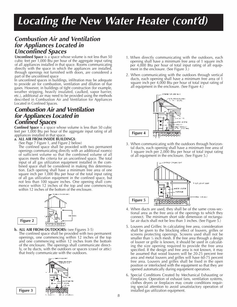
(See Page 7 Figure 1, and Figure 2 below)The confined space shall be provided with two permanentopenings communicating directly with an additional room(s)of sufficient volume so that the combined volume of allspaces meets the criteria for an unconfined space. The totalinput of all gas utilization equipment installed in the com-bined space shall be considered in making this determina-tion. Each opening shall have a minimum free area of onesquare inch per 1,000 Btu per hour of the total input ratingof all gas utilization equipment in the confined space, butnot less than 100 square inches. One opening shall com-mence within 12 inches of the top and one commencingwithin 12 inches of the bottom of the enclosure.
b. ALL AIR FROM OUTDOORS: (see Figures 3-5)The confined space shall be provided with two permanentopenings, one commencing within 12 inches of the topand one commencing within 12 inches from the bottomof the enclosure. The openings shall communicate direct-ly, or by ducts, with the outdoors or spaces (crawl or attic)that freely communicate with the outdoors.
1. When directly communicating with the outdoors, eachopening shall have a minimum free area of 1 square inchper 4,000 Btu per hour of total input rating of all equip-ment in the enclosure. (See Figure 3.)
2. When communicating with the outdoors through verticalducts, each opening shall have a minimum free area of 1square inch per 4,000 Btu per hour of total input rating ofall equipment in the enclosure. (See Figure 4.)
3. When communicating with the outdoors through horizon-tal ducts, each opening shall have a minimum free area of1 square inch per 2,000 Btu per hour of total input ratingof all equipment in the enclosure. (See Figure 5.)
4. When ducts are used, they shall be of the same cross-sec-tional area as the free area of the openings to which theyconnect. The minimum short side dimension of rectangu-lar air ducts shall not be less than 3 inches. (See Figure 5.)
5. Louvers and Grilles: In calculating free area, considerationshall be given to the blocking effect of louvers, grilles orscreens protecting openings. Screens used shall not besmaller than 1⁄4 inch mesh. If the free area through a designof louver or grille is known, it should be used in calculat-ing the size opening required to provide the free areaspecified. If the design and free area is not known, it maybe assumed that wood louvers will be 20-25 percent freearea and metal louvers and grilles will have 60-75 percentfree area. Louvers and grilles shall be fixed in the openposition or interlocked with the equipment so that they areopened automatically during equipment operation.
6. Special Conditions Created by Mechanical Exhausting orFireplaces: Operation of exhaust fans, ventilation systems,clothes dryers or fireplaces may create conditions requir-ing special attention to avoid unsatisfactory operation ofinstalled gas utilization equipment.
Locating the New Water Heater (cont’d)
Figure 2
Figure 4
Figure 5
Figure 38

This water heater shall not be connected to any heatingsystems or component(s) used with a non-potable waterheating appliance.
If a water heater is installed in a closed water supply sys-tem, such as one having a back-flow preventer, checkvalve, water meter with check valve, etc. in the coldwater supply, means shall be provided to control thermalexpansion. Contact the water supplier or plumbinginspector on how to control this situation.
NOTE: To protect against untimely corrosion of hot andcold water fittings, it is strongly recommended that di-electric unions or couplings be installed on this waterheater when connected to copper pipe.
The illustration shows the attachment of the water pipingto the water heater. The water heater is equipped with 3⁄4″water connections.
NOTE: If using copper tubing, solder tubing to anadapter before attaching the adapter to the cold waterinlet connection. Do not solder the cold water supplyline directly to the cold water inlet. It will harm the diptube and damage the tank.
Installing the New Water Heater
Water Piping
9
WARNINGHOTTER WATER CAN SCALD: Water heaters are intended toproduce hot water. Water heated to a temperature which willsatisfy clothes washing, dish washing, and other sanitizingneeds can scald and permanently injure you upon contact.Some people are more likely to be permanently injured byhot water than others. These include the elderly, children, theinfirm, or physically/mentally handicapped. If anyone usinghot water in your home fits into one of these groups or ifthere is a local code or state law requiring a certain tempera-ture water at the hot water tap, then you must take specialprecautions. In addition to using the lowest possible tempera-ture setting that satisfies your hot water needs, a means suchas a mixing valve, should be used at the hot water taps usedby these people or at the water heater. Mixing valves areavailable at plumbing supply or hardware stores. Follow man-ufacturers instructions for installation of the valves. Beforechanging the factory setting on the thermostat, read the“Temperature Regulation” section in this manual.
Installing the New Water Heater (cont’d)
Temperature-Pressure Relief Valve
TEMPERATURE-PRESSURE
RELIEF VALVE
DRAFT HOOD
SHUTOFFVALVE
COLDHOT
HOT COLD
10
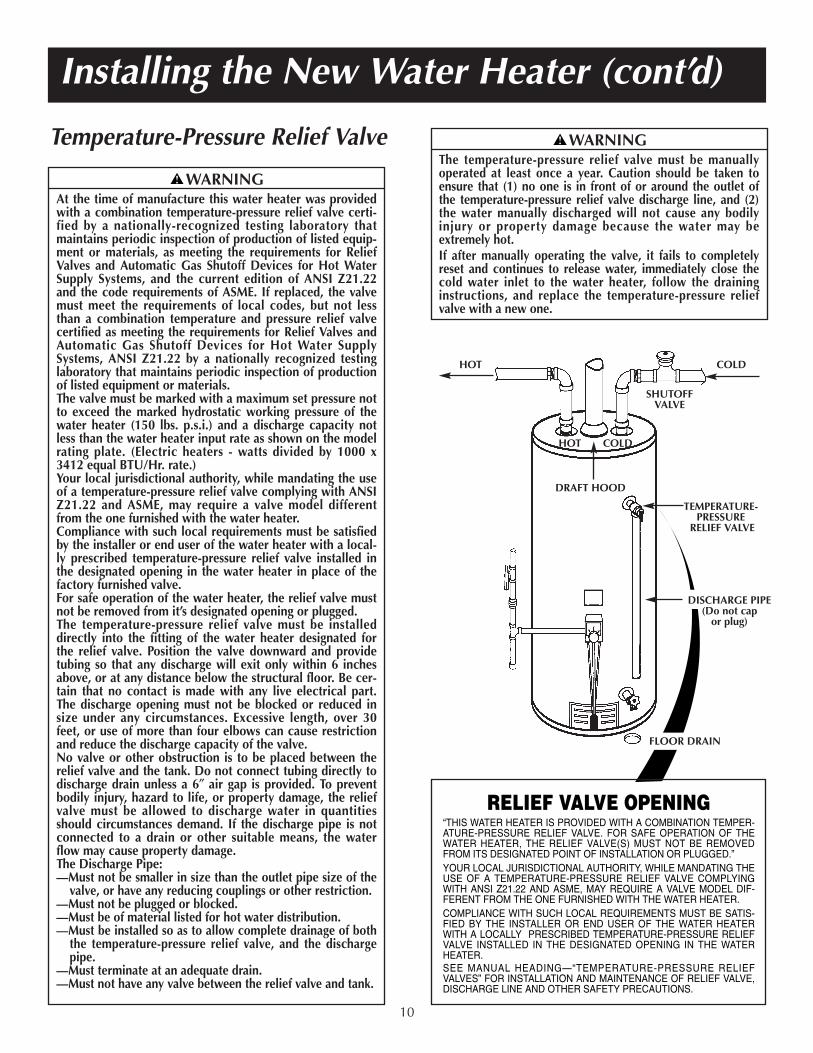
RELIEF VALVE OPENING“THIS WATER HEATER IS PROVIDED WITH A COMBINATION TEMPER-ATURE-PRESSURE RELIEF VALVE. FOR SAFE OPERATION OF THEWATER HEATER, THE RELIEF VALVE(S) MUST NOT BE REMOVEDFROM ITS DESIGNATED POINT OF INSTALLATION OR PLUGGED.”YOUR LOCAL JURISDICTIONAL AUTHORITY, WHILE MANDATING THEUSE OF A TEMPERATURE-PRESSURE RELIEF VALVE COMPLYINGWITH ANSI Z21.22 AND ASME, MAY REQUIRE A VALVE MODEL DIF-FERENT FROM THE ONE FURNISHED WITH THE WATER HEATER.COMPLIANCE WITH SUCH LOCAL REQUIREMENTS MUST BE SATIS-FIED BY THE INSTALLER OR END USER OF THE WATER HEATERWITH A LOCALLY PRESCRIBED TEMPERATURE-PRESSURE RELIEFVALVE INSTALLED IN THE DESIGNATED OPENING IN THE WATERHEATER.SEE MANUAL HEADING—“TEMPERATURE-PRESSURE RELIEFVALVES” FOR INSTALLATION AND MAINTENANCE OF RELIEF VALVE,DISCHARGE LINE AND OTHER SAFETY PRECAUTIONS.
FLOOR DRAIN
DISCHARGE PIPE(Do not cap
or plug)
WARNINGAt the time of manufacture this water heater was providedwith a combination temperature-pressure relief valve certi-fied by a nationally-recognized testing laboratory thatmaintains periodic inspection of production of listed equip-ment or materials, as meeting the requirements for ReliefValves and Automatic Gas Shutoff Devices for Hot WaterSupply Systems, and the current edition of ANSI Z21.22and the code requirements of ASME. If replaced, the valvemust meet the requirements of local codes, but not lessthan a combination temperature and pressure relief valvecertified as meeting the requirements for Relief Valves andAutomatic Gas Shutoff Devices for Hot Water SupplySystems, ANSI Z21.22 by a nationally recognized testinglaboratory that maintains periodic inspection of productionof listed equipment or materials.The valve must be marked with a maximum set pressure notto exceed the marked hydrostatic working pressure of thewater heater (150 lbs. p.s.i.) and a discharge capacity notless than the water heater input rate as shown on the modelrating plate. (Electric heaters - watts divided by 1000 x3412 equal BTU/Hr. rate.)Your local jurisdictional authority, while mandating the useof a temperature-pressure relief valve complying with ANSIZ21.22 and ASME, may require a valve model differentfrom the one furnished with the water heater.Compliance with such local requirements must be satisfiedby the installer or end user of the water heater with a local-ly prescribed temperature-pressure relief valve installed inthe designated opening in the water heater in place of thefactory furnished valve.For safe operation of the water heater, the relief valve mustnot be removed from it’s designated opening or plugged.The temperature-pressure relief valve must be installeddirectly into the fitting of the water heater designated forthe relief valve. Position the valve downward and providetubing so that any discharge will exit only within 6 inchesabove, or at any distance below the structural floor. Be cer-tain that no contact is made with any live electrical part.The discharge opening must not be blocked or reduced insize under any circumstances. Excessive length, over 30feet, or use of more than four elbows can cause restrictionand reduce the discharge capacity of the valve.No valve or other obstruction is to be placed between therelief valve and the tank. Do not connect tubing directly todischarge drain unless a 6″ air gap is provided. To preventbodily injury, hazard to life, or property damage, the reliefvalve must be allowed to discharge water in quantitiesshould circumstances demand. If the discharge pipe is notconnected to a drain or other suitable means, the waterflow may cause property damage.The Discharge Pipe:—Must not be smaller in size than the outlet pipe size of the
valve, or have any reducing couplings or other restriction.—Must not be plugged or blocked.—Must be of material listed for hot water distribution.—Must be installed so as to allow complete drainage of both
the temperature-pressure relief valve, and the dischargepipe.
—Must terminate at an adequate drain.—Must not have any valve between the relief valve and tank.
WARNINGThe temperature-pressure relief valve must be manuallyoperated at least once a year. Caution should be taken toensure that (1) no one is in front of or around the outlet ofthe temperature-pressure relief valve discharge line, and (2)the water manually discharged will not cause any bodilyinjury or property damage because the water may beextremely hot.If after manually operating the valve, it fails to completelyreset and continues to release water, immediately close thecold water inlet to the water heater, follow the draininginstructions, and replace the temperature-pressure reliefvalve with a new one.
Filling the Water Heater
To fill the water heater with water:1. Close the water heater drain valve by turning the han-
dle to the right (clockwise). The drain valve is on thelower front of the water heater.
2. Open the cold water supply valve to the water heater.NOTE: The cold water supply valve must be left openwhen the water heater is in use.
3. To insure complete filling of the tank, allow air to exitby opening the nearest hot water faucet. Allow waterto run until a constant flow is obtained. This will let airout of the water heater and the piping.
4. Check all new water piping for leaks. Repair as needed.
Check the venting system for signs of obstruction or deterio-ration and replace if needed.The combustion and ventilation air flow must not beobstructed.
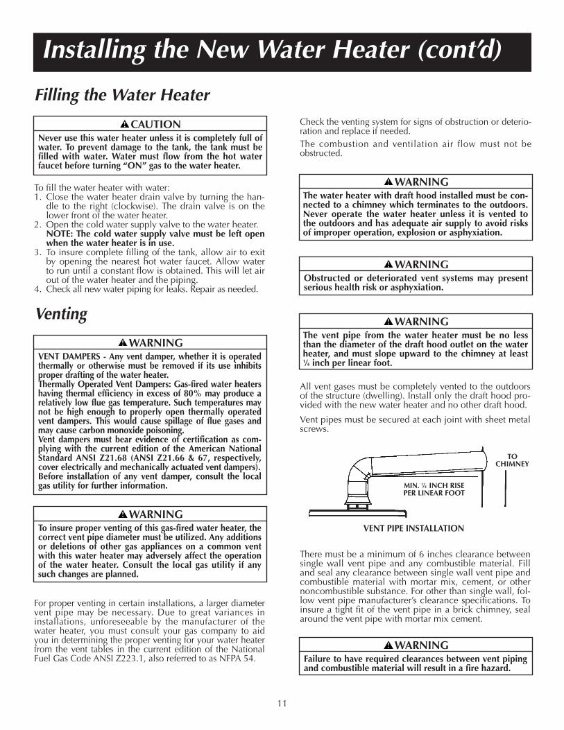
All vent gases must be completely vented to the outdoorsof the structure (dwelling). Install only the draft hood pro-vided with the new water heater and no other draft hood.
Vent pipes must be secured at each joint with sheet metalscrews.
MIN. 1⁄4 INCH RISEPER LINEAR FOOT
TOCHIMNEY
There must be a minimum of 6 inches clearance betweensingle wall vent pipe and any combustible material. Filland seal any clearance between single wall vent pipe andcombustible material with mortar mix, cement, or othernoncombustible substance. For other than single wall, fol-low vent pipe manufacturer’s clearance specifications. Toinsure a tight fit of the vent pipe in a brick chimney, sealaround the vent pipe with mortar mix cement.
Installing the New Water Heater (cont’d)
VENT PIPE INSTALLATION
For proper venting in certain installations, a larger diametervent pipe may be necessary. Due to great variances ininstallations, unforeseeable by the manufacturer of thewater heater, you must consult your gas company to aidyou in determining the proper venting for your water heaterfrom the vent tables in the current edition of the NationalFuel Gas Code ANSI Z223.1, also referred to as NFPA 54.
11
Venting
CAUTIONNever use this water heater unless it is completely full ofwater. To prevent damage to the tank, the tank must befilled with water. Water must flow from the hot waterfaucet before turning “ON” gas to the water heater.
WARNINGTo insure proper venting of this gas-fired water heater, thecorrect vent pipe diameter must be utilized. Any additionsor deletions of other gas appliances on a common ventwith this water heater may adversely affect the operationof the water heater. Consult the local gas utility if anysuch changes are planned.
WARNINGFailure to have required clearances between vent pipingand combustible material will result in a fire hazard.
WARNINGThe vent pipe from the water heater must be no lessthan the diameter of the draft hood outlet on the waterheater, and must slope upward to the chimney at least1⁄4 inch per linear foot.
WARNINGObstructed or deteriorated vent systems may presentserious health risk or asphyxiation.
WARNINGThe water heater with draft hood installed must be con-nected to a chimney which terminates to the outdoors.Never operate the water heater unless it is vented tothe outdoors and has adequate air supply to avoid risksof improper operation, explosion or asphyxiation.
WARNINGVENT DAMPERS - Any vent damper, whether it is operatedthermally or otherwise must be removed if its use inhibitsproper drafting of the water heater.Thermally Operated Vent Dampers: Gas-fired water heatershaving thermal efficiency in excess of 80% may produce arelatively low flue gas temperature. Such temperatures maynot be high enough to properly open thermally operatedvent dampers. This would cause spillage of flue gases andmay cause carbon monoxide poisoning.Vent dampers must bear evidence of certification as com-plying with the current edition of the American NationalStandard ANSI Z21.68 (ANSI Z21.66 & 67, respectively,cover electrically and mechanically actuated vent dampers).Before installation of any vent damper, consult the localgas utility for further information.
A gas line of sufficient size must be run to the water heater.Consult the current edition of National Fuel Gas Code ANSIZ223.1, also referred to as NFPA 54 and the gas company con-cerning pipe size.
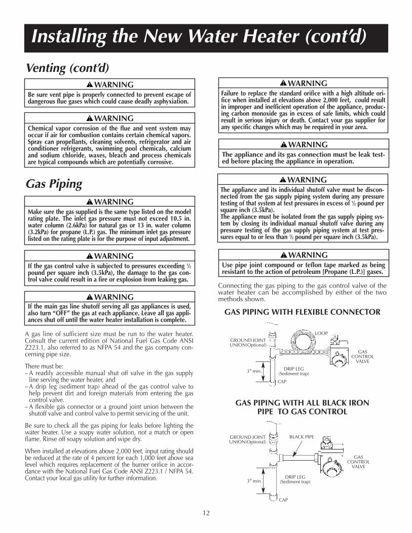
There must be:– A readily accessible manual shut off valve in the gas supply
line serving the water heater, and– A drip leg (sediment trap) ahead of the gas control valve to
help prevent dirt and foreign materials from entering the gascontrol valve.
– A flexible gas connector or a ground joint union between theshutoff valve and control valve to permit servicing of the unit.
Be sure to check all the gas piping for leaks before lighting thewater heater. Use a soapy water solution, not a match or openflame. Rinse off soapy solution and wipe dry.
When installed at elevations above 2,000 feet, input rating shouldbe reduced at the rate of 4 percent for each 1,000 feet above sealevel which requires replacement of the burner orifice in accor-dance with the National Fuel Gas Code ANSI Z223.1 / NFPA 54.Contact your local gas utility for further information.
Connecting the gas piping to the gas control valve of thewater heater can be accomplished by either of the twomethods shown.
Installing the New Water Heater (cont’d)
Gas Piping
Venting (cont’d)
12
GAS PIPING WITH FLEXIBLE CONNECTOR
GAS PIPING WITH ALL BLACK IRON PIPE TO GAS CONTROL
GROUND JOINTUNION(Optional)
3″ min.
LOOP
GASCONTROL
VALVE
DRIP LEG(Sediment trap)
CAP
3″ min.
GROUND JOINTUNION(Optional)
GASCONTROL
VALVE
BLACK PIPE
DRIP LEG(Sediment trap)
CAP
WARNINGBe sure vent pipe is properly connected to prevent escape ofdangerous flue gases which could cause deadly asphyxiation.
WARNINGChemical vapor corrosion of the flue and vent system mayoccur if air for combustion contains certain chemical vapors.Spray can propellants, cleaning solvents, refrigerator and airconditioner refrigerants, swimming pool chemicals, calciumand sodium chloride, waxes, bleach and process chemicalsare typical compounds which are potentially corrosive.
WARNINGMake sure the gas supplied is the same type listed on the modelrating plate. The inlet gas pressure must not exceed 10.5 in.water column (2.6kPa) for natural gas or 13 in. water column(3.2kPa) for propane (L.P.) gas. The minimum inlet gas pressurelisted on the rating plate is for the purpose of input adjustment.
WARNINGThe appliance and its individual shutoff valve must be discon-nected from the gas supply piping system during any pressuretesting of that system at test pressures in excess of 1⁄2 pound persquare inch (3.5kPa).The appliance must be isolated from the gas supply piping sys-tem by closing its individual manual shutoff valve during anypressure testing of the gas supply piping system at test pres-sures equal to or less than 1⁄2 pound per square inch (3.5kPa).
WARNINGUse pipe joint compound or teflon tape marked as beingresistant to the action of petroleum [Propane (L.P.)] gases.
WARNINGIf the gas control valve is subjected to pressures exceeding 1⁄2pound per square inch (3.5kPa), the damage to the gas con-trol valve could result in a fire or explosion from leaking gas.
WARNINGIf the main gas line shutoff serving all gas appliances is used,also turn “OFF” the gas at each appliance. Leave all gas appli-ances shut off until the water heater installation is complete.
WARNINGThe appliance and its gas connection must be leak test-ed before placing the appliance in operation.
WARNINGFailure to replace the standard orifice with a high altitude ori-fice when installed at elevations above 2,000 feet, could resultin improper and inefficient operation of the appliance, produc-ing carbon monoxide gas in excess of safe limits, which couldresult in serious injury or death. Contact your gas supplier forany specific changes which may be required in your area.

Installation ChecklistBEFORE LIGHTING THE PILOT:
1. Check the gas lines for leaks.a. Use a soapy water solution. DO NOT test for gas
leaks using a match or open flame.b. Brush the soapy water solution on all gas pipes,
joints and fittings.c. Check for bubbling soap. This means you have a
leak. Turn “OFF” gas and make the necessaryrepairs.
d. Recheck for leaks.e. Rinse off soapy solution and wipe dry.
VENT PIPE TOOUTDOORSOR CHIMNEY
FLOOR DRAIN
HOT COLD
DRAIN VALVE
TEMPERATURE-PRESSURERELIEF VALVE
UNION
SHUTOFF VALVE
DISCHARGE PIPE(Do not cap or plug)
MODEL RATING PLATE
DRAFT HOOD
2. Is the new temperature-pressure relief valve properlyinstalled and piped to an adequate drain? See“Temperature-Pressure Relief Valve” section.
3. Are the cold and hot water lines connected to thewater heater correctly? See “Water Piping” instructionsin the “Installing the New Water Heater” section.
4. Is the water heater completely filled with water? See“Filling the Water Heater” instructions in the“Installing the New Water Heater” section.
5. Will a water leak damage anything? See the “Locatingthe New Water Heater” section.
6. Is there proper clearance between the water heaterand anything that might catch fire? See the “Locatingthe New Water Heater” section.
7. Do you have adequate ventilation so that the waterheater will operate properly? See “Combustion Airand Ventilation” in the “Locating the New WaterHeater” section.
8. Is the draft hood vent piping properly secured? See“Venting” instructions in the “Installing the NewWater Heater” section.
9. Is there proper clearance between the vent pipe andanything that might catch on fire? See “Venting”instructions in the “Installing the New Water Heater”section.
10. Is the vent pipe properly sloped and does the vent ter-minate outdoors? See “Venting” instructions in the“Installing the New Water Heater” section.
11. Do you need to call your gas company to check thegas pipe and its hookup?
Installing the New Water Heater (cont’d)
13
WARNINGContaminants in the gas lines may cause improper opera-tion of the gas control valve that may result in fire or explo-sion. Before attaching the gas line be sure that all gas pipe isclean on the inside. To trap any dirt or foreign material inthe gas supply line, a drip leg (sometimes called a sedimenttrap) must be incorporated in the piping. The drip leg mustbe readily accessible. Install in accordance with the “GasPiping” section. Refer to the current edition of the NationalFuel Gas Code, ANSI Z223.1, also referred to as NFPA 54.
Lighting and operating instructions are located on front ofthe water heater, above or to one side of the gas controlvalve.
CHECK FOR LEAKS
Be sure to check all your gas pipes for leaks before light-ing your water heater. Use a soapy water solution, not amatch or open flame. Check the factory gas fittings afterpilot is lit and gas control knob is still in “PILOT” position.Then, check the fittings when the main burner is turned“ON”. Use a soapy water solution for this, too.
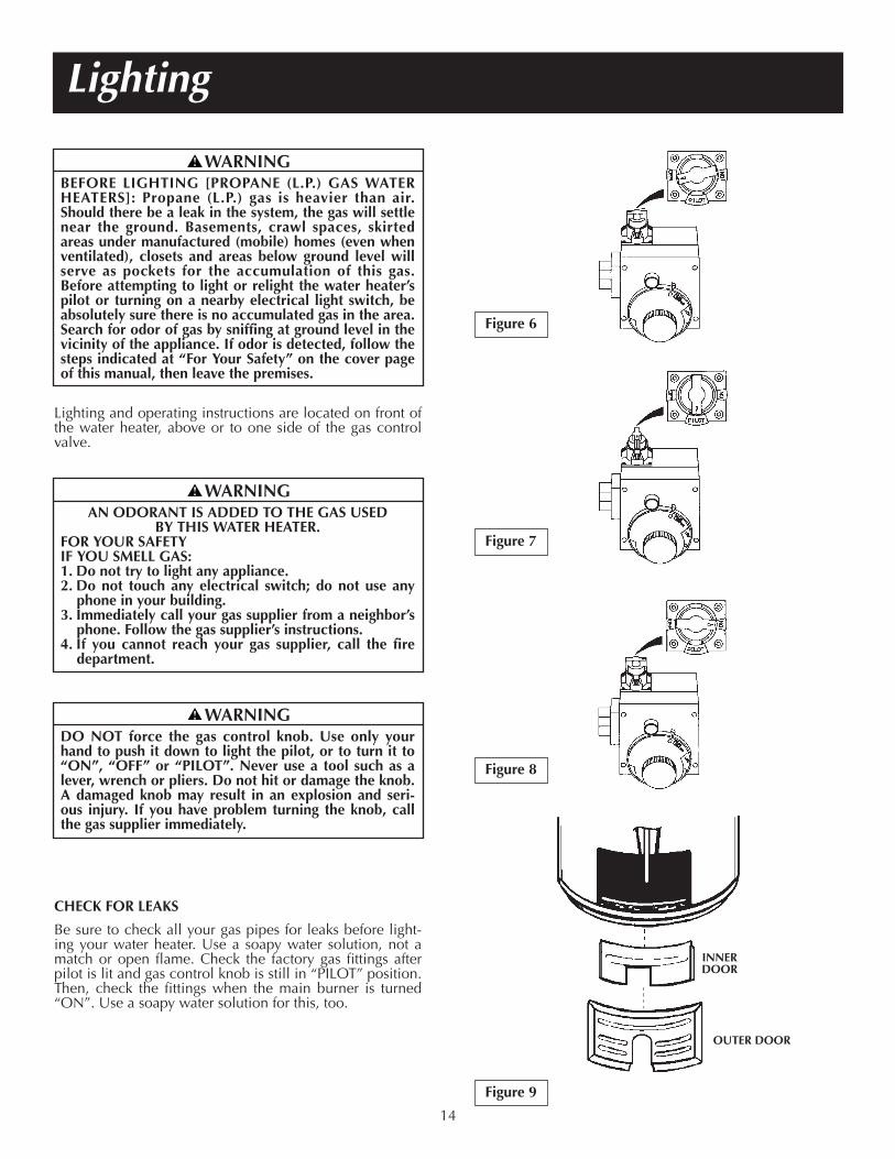
Figure 6
Figure 7
Figure 8
INNERDOOR
Lighting
Figure 9
OUTER DOOR
14
WARNINGBEFORE LIGHTING [PROPANE (L.P.) GAS WATERHEATERS]: Propane (L.P.) gas is heavier than air.Should there be a leak in the system, the gas will settlenear the ground. Basements, crawl spaces, skirtedareas under manufactured (mobile) homes (even whenventilated), closets and areas below ground level willserve as pockets for the accumulation of this gas.Before attempting to light or relight the water heater’spilot or turning on a nearby electrical light switch, beabsolutely sure there is no accumulated gas in the area.Search for odor of gas by sniffing at ground level in thevicinity of the appliance. If odor is detected, follow thesteps indicated at “For Your Safety” on the cover pageof this manual, then leave the premises.
WARNINGAN ODORANT IS ADDED TO THE GAS USED
BY THIS WATER HEATER.FOR YOUR SAFETYIF YOU SMELL GAS:1. Do not try to light any appliance.2. Do not touch any electrical switch; do not use any
phone in your building.3. Immediately call your gas supplier from a neighbor’s
phone. Follow the gas supplier’s instructions.4. If you cannot reach your gas supplier, call the fire
department.
WARNINGDO NOT force the gas control knob. Use only yourhand to push it down to light the pilot, or to turn it to“ON”, “OFF” or “PILOT”. Never use a tool such as alever, wrench or pliers. Do not hit or damage the knob.A damaged knob may result in an explosion and seri-ous injury. If you have problem turning the knob, callthe gas supplier immediately.
Lighting (cont’d)
15
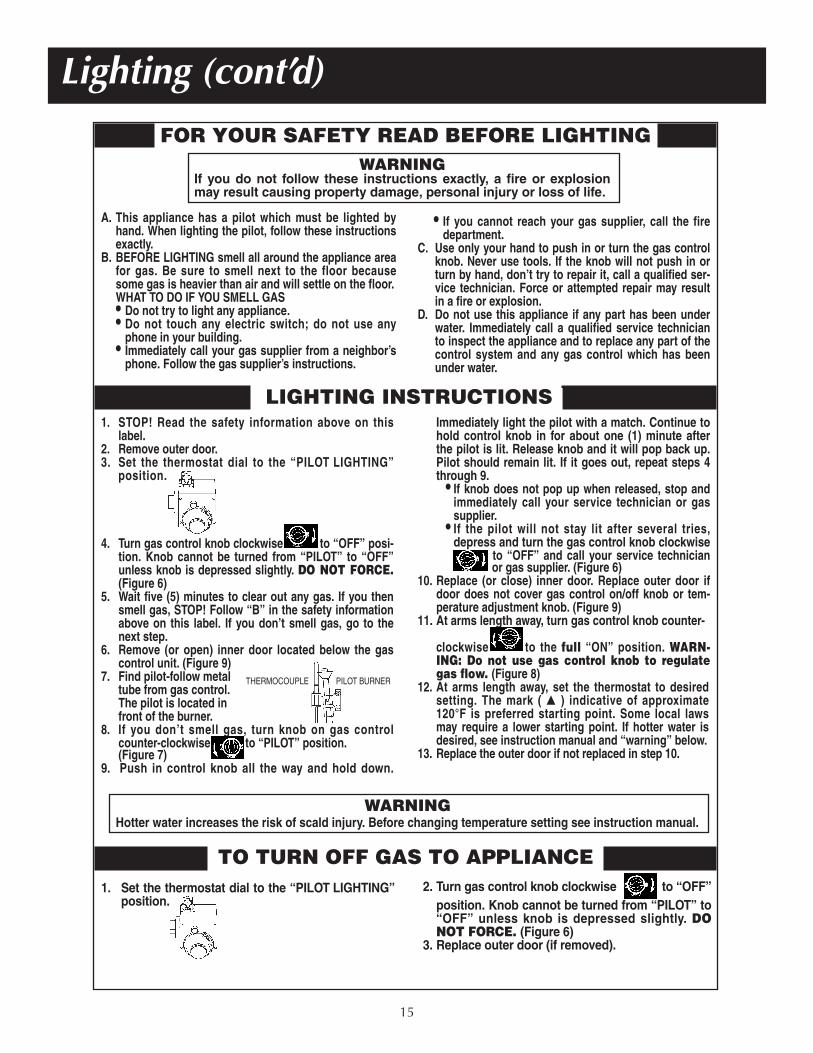
FOR YOUR SAFETY READ BEFORE LIGHTINGWARNING
If you do not follow these instructions exactly, a fire or explosionmay result causing property damage, personal injury or loss of life.
A. This appliance has a pilot which must be lighted byhand. When lighting the pilot, follow these instructionsexactly.
B. BEFORE LIGHTING smell all around the appliance areafor gas. Be sure to smell next to the floor becausesome gas is heavier than air and will settle on the floor.WHAT TO DO IF YOU SMELL GAS• Do not try to light any appliance.• Do not touch any electric switch; do not use any
phone in your building.• Immediately call your gas supplier from a neighbor’s
phone. Follow the gas supplier’s instructions.
• If you cannot reach your gas supplier, call the firedepartment.
C. Use only your hand to push in or turn the gas controlknob. Never use tools. If the knob will not push in orturn by hand, don’t try to repair it, call a qualified ser-vice technician. Force or attempted repair may resultin a fire or explosion.
D. Do not use this appliance if any part has been underwater. Immediately call a qualified service technicianto inspect the appliance and to replace any part of thecontrol system and any gas control which has beenunder water.
LIGHTING INSTRUCTIONS1. STOP! Read the safety information above on this
label.2. Remove outer door.3. Set the thermostat dial to the “PILOT LIGHTING”
position.
4. Turn gas control knob clockwise to “OFF” posi-tion. Knob cannot be turned from “PILOT” to “OFF”unless knob is depressed slightly. DO NOT FORCE.(Figure 6)
5. Wait five (5) minutes to clear out any gas. If you thensmell gas, STOP! Follow “B” in the safety informationabove on this label. If you don’t smell gas, go to thenext step.
6. Remove (or open) inner door located below the gascontrol unit. (Figure 9)
7. Find pilot-follow metaltube from gas control.The pilot is located infront of the burner.
8. If you don’t smell gas, turn knob on gas controlcounter-clockwise to “PILOT” position. (Figure 7)
9. Push in control knob all the way and hold down.
Immediately light the pilot with a match. Continue tohold control knob in for about one (1) minute afterthe pilot is lit. Release knob and it will pop back up.Pilot should remain lit. If it goes out, repeat steps 4through 9.
• If knob does not pop up when released, stop andimmediately call your service technician or gassupplier.
• If the pilot will not stay lit after several tries,depress and turn the gas control knob clockwise
to “OFF” and call your service technicianor gas supplier. (Figure 6)
10. Replace (or close) inner door. Replace outer door ifdoor does not cover gas control on/off knob or tem-perature adjustment knob. (Figure 9)
11. At arms length away, turn gas control knob counter-
clockwise to the full “ON” position. WARN-ING: Do not use gas control knob to regulategas flow. (Figure 8)
12. At arms length away, set the thermostat to desiredsetting. The mark ( � ) indicative of approximate120°F is preferred starting point. Some local lawsmay require a lower starting point. If hotter water isdesired, see instruction manual and “warning” below.
13. Replace the outer door if not replaced in step 10.
WARNINGHotter water increases the risk of scald injury. Before changing temperature setting see instruction manual.
TO TURN OFF GAS TO APPLIANCE1. Set the thermostat dial to the “PILOT LIGHTING”
position.2. Turn gas control knob clockwise to “OFF”
position. Knob cannot be turned from “PILOT” to“OFF” unless knob is depressed slightly. DONOT FORCE. (Figure 6)
3. Replace outer door (if removed).
THERMOCOUPLE PILOT BURNER
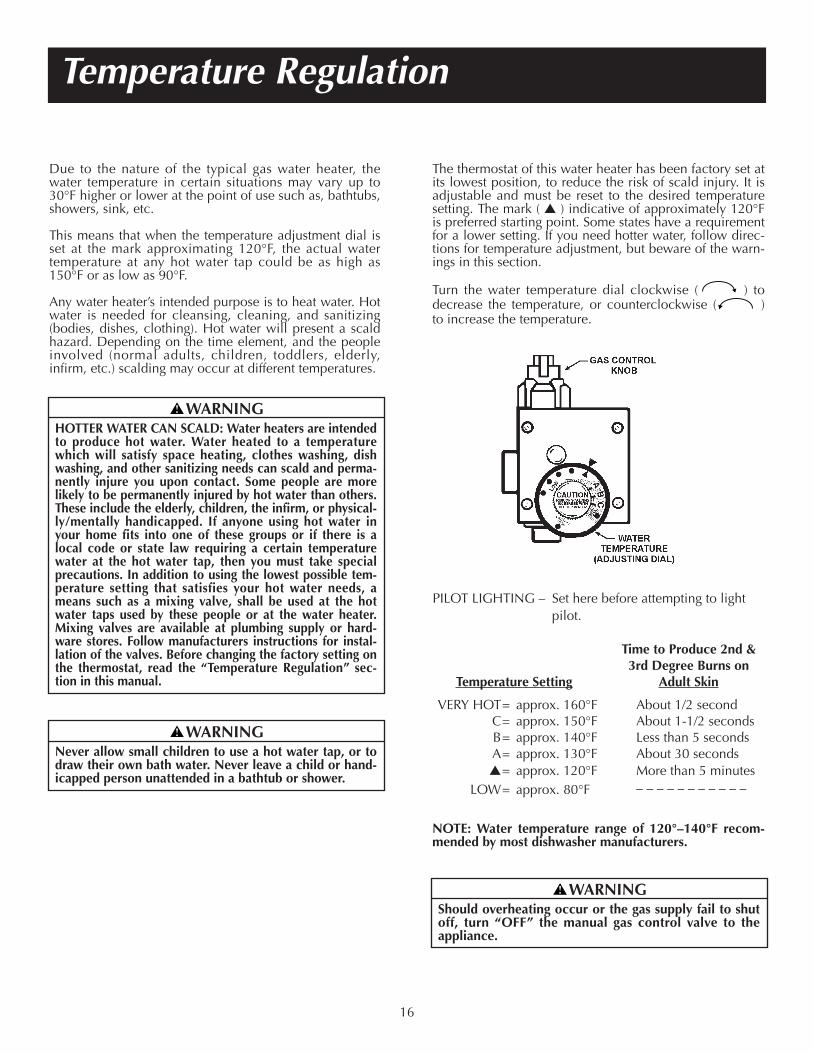
Due to the nature of the typical gas water heater, thewater temperature in certain situations may vary up to30°F higher or lower at the point of use such as, bathtubs,showers, sink, etc.
This means that when the temperature adjustment dial isset at the mark approximating 120°F, the actual watertemperature at any hot water tap could be as high as150°F or as low as 90°F.
Any water heater’s intended purpose is to heat water. Hotwater is needed for cleansing, cleaning, and sanitizing(bodies, dishes, clothing). Hot water will present a scaldhazard. Depending on the time element, and the peopleinvolved (normal adults, children, toddlers, elderly,infirm, etc.) scalding may occur at different temperatures.
The thermostat of this water heater has been factory set atits lowest position, to reduce the risk of scald injury. It isadjustable and must be reset to the desired temperaturesetting. The mark ( � ) indicative of approximately 120°Fis preferred starting point. Some states have a requirementfor a lower setting. If you need hotter water, follow direc-tions for temperature adjustment, but beware of the warn-ings in this section.
Turn the water temperature dial clockwise ( ) todecrease the temperature, or counterclockwise ( )to increase the temperature.
Temperature Regulation
16
WARNINGHOTTER WATER CAN SCALD: Water heaters are intendedto produce hot water. Water heated to a temperaturewhich will satisfy space heating, clothes washing, dishwashing, and other sanitizing needs can scald and perma-nently injure you upon contact. Some people are morelikely to be permanently injured by hot water than others.These include the elderly, children, the infirm, or physical-ly/mentally handicapped. If anyone using hot water inyour home fits into one of these groups or if there is alocal code or state law requiring a certain temperaturewater at the hot water tap, then you must take specialprecautions. In addition to using the lowest possible tem-perature setting that satisfies your hot water needs, ameans such as a mixing valve, shall be used at the hotwater taps used by these people or at the water heater.Mixing valves are available at plumbing supply or hard-ware stores. Follow manufacturers instructions for instal-lation of the valves. Before changing the factory setting onthe thermostat, read the “Temperature Regulation” sec-tion in this manual.
WARNINGNever allow small children to use a hot water tap, or todraw their own bath water. Never leave a child or hand-icapped person unattended in a bathtub or shower.
WARNINGShould overheating occur or the gas supply fail to shutoff, turn “OFF” the manual gas control valve to theappliance.
PILOT LIGHTING – Set here before attempting to lightpilot.
Time to Produce 2nd & 3rd Degree Burns on
Temperature Setting Adult Skin
VERY HOT= approx. 160°F About 1/2 secondC= approx. 150°F About 1-1/2 secondsB= approx. 140°F Less than 5 secondsA= approx. 130°F About 30 seconds�= approx. 120°F More than 5 minutes
LOW= approx. 80°F _ _ _ _ _ _ _ _ _ _ _
NOTE: Water temperature range of 120°–140°F recom-mended by most dishwasher manufacturers.
Start Up ConditionsDRAFT HOOD OPERATIONCheck draft hood operation by performing a worst case depressur-ization of the building. With all doors and windows closed, andwith all air handling equipment and exhaust fans operating, suchfurnaces, clothes dryers, range hoods and bathroom fans, a matchflame should still be drawn into the draft hood of the water heaterwith its burner firing. If the flame is not drawn toward the drafthood, shut off the water heater and make necessary air supplychanges to correct.
CONDENSATIONWhenever the water heater is filled with cold water, a certainamount of condensation will form while the burner is on. A waterheater may appear to be leaking when in fact the water is conden-sation. This usually happens when:
a. When a new water heater is filled with cold water for thefirst time.
b. When gas burns and water vapor is produced in waterheaters, particularly high efficiency models where flue tem-peratures are lower.
c. When you use large amounts of hot water in a short timeand the refill water is very cold.
Moisture from the products of combustion condense on the coolertank surfaces and form drops of water which may fall onto theburner or other hot surfaces to produce a “sizzling” or “frying”noise.
Excessive condensation can cause pilot outage due to water run-ning down the flue tube onto the main burner and putting out thepilot.
Because of the suddenness and amount of water, condensationwater may be diagnosed as a “tank leak”. After the water in thetank warms up (about 1-2 hours), the condition should disappear.
Do not assume the water heater is leaking until there has beenenough time for the water in the tank to warm up.
An undersized water heater will cause more condensation. Thewater heater must be sized properly to meet the family’s demandsfor hot water including dishwashers, washing machines and show-er heads.
Excessive condensation may be noticed during the winter andearly spring months when incoming water temperatures are attheir lowest.
Good venting is essential for a gas fired water heater to operateproperly as well as to carry away products of combustion andwater vapor.
SMOKE/ODORIt is not uncommon to experience a small amount of smoke andodor during the initial start-up. This is due to burning off of oilfrom metal parts, and will disappear in a short while.
THERMAL EXPANSIONWater supply systems may, because of such events as high linepressure, frequent cut-offs, the effects of water hammer amongothers, have installed devices such as pressure reducing valves,check valves, back flow preventers, etc. to control these types of
problems. When these devices are not equipped with an internalby-pass, and no other measures are taken, the devices cause thewater system to be closed. As water is heated, it expands (thermalexpansion) and closed systems do not allow for the expansion ofheated water.
The water within the water heater tank expands as it is heated andincreases the pressure of the water system. If the relieving point ofthe water heater’s temperature-pressure relief valve is reached, thevalve will relieve the excess pressure. The temperature-pressurerelief valve is not intended for the constant relief of thermalexpansion. This is an unacceptable condition and must be corrected.
It is recommended that any devices installed which could create aclosed system have a by-pass and/or the system have an expan-sion tank to relieve the pressure built by thermal expansion in thewater system. Expansion tanks are available for ordering through alocal plumbing contractor. Contact the local water supplier and/orplumbing inspector for assistance in controlling these situations.
STRANGE SOUNDSPossible noises due to expansion and contraction of some metalparts during periods of heat-up and cool-down do not representharmful or dangerous conditions.Condensation causes sizzling and popping with the burner areaduring heating and cooling periods and should be considerednormal. See “Condensation” in this section.
Operational ConditionsSMELLY WATERIn each water heater there is installed at least one anode rod (seeparts section) for corrosion protection of the tank. Certain waterconditions will cause a reaction between this rod and the water.The most common complaint associated with the anode rod isone of a “rotten egg smell.” This odor is derived from hydrogensulfide gas dissolved in the water. The smell is the result of fourfactors which must all be present for the odor to develop:
a. a concentration of sulfate in the supply water.b. little or no dissolved oxygen in the water.c. a sulfate reducing bacteria within the water heater. (This
harmless bacteria is non-toxic to humans.)d. an excess of active hydrogen in the tank. This is caused by
the corrosion protective action of the anode.
Smelly water may be eliminated or reduced in some water heatermodels by replacing the anode(s) with one of less active material,and then chlorinating the water heater tank and all hot waterlines. Contact the local water heater supplier for further informa-tion concerning an Anode Replacement Kit #9000029 and thisChlorination Treatment.
If the smelly water persists after the anode replacement and chlo-rination treatment, we can only suggest that continuous chlorina-tion and filtering conditioning equipment be considered to elimi-nate the water problem.
Do not remove the anode leaving the tank unprotected. By doingso, all warranty on the water heater tank is voided.
For Your Information
17
Venting System InspectionAt least once a year a visual inspection should be made ofthe venting system. You should look for:1. Obstructions which could cause improper venting. The
combustion and ventilation air flow must not beobstructed.
2. Damage or deterioration which could cause improperventing or leakage of combustion products.
3. Rusted flakes around top of water heater.
HIGH TEMPERATURE SHUT OFF SYSTEMThis water heater is equipped with an automatic gas shutoff system. This system works when high water tempera-tures are present. Turn “OFF” the entire gas supply to thewater heater. The high temperature shut off is built intothe gas control valve. It is non-resettable. If the high tem-perature shut off activates, the gas control valve must bereplaced. Contact the local gas utility.
NOT ENOUGH OR NO HOT WATER1. Check the manual gas shut off valve to be sure it is open.
2. Check the pilot flame. It may have gone out. All modelshave an opening behind the outer door for viewing thepilot.
3. If the pilot is not lit, follow the “Lighting” instructions inthis manual or located above the gas control valve on thewater heater to relight the pilot. If the water was extreme-ly hot and is now cold, the high limit safety temperatureshut off may have put out the burner and pilot. The gascontrol valve now must be changed.
4. The gas control knob must be turned to the “ON” position.
5. The temperature adjustment dial may be set too low. Seethe “Temperature Regulation” section.
6. The gas company can check the gas input to see if it iscorrect. An underfired water heater will not heat water asquickly.
7. Look for leaking or open hot water faucets. Make sure allare closed.
8. The cold water inlet temperature may be colder duringthe winter months. It will take longer to heat the waterand seem like less hot water.
9. If you cannot find what is wrong, call the local gas utilityand/or plumbing contractor.
WATER IS TOO HOT
1. The temperature adjustment dial may be set too high. Seethe “Temperature Regulation” section.
NOTE: A period of time is necessary after an adjustmenthas been made for the water temperature to reach thenew temperature setting.
2. If lower temperature settings will not lower the water tem-perature, call the local gas utility.
For Your Information (cont’d)“AIR” IN HOT WATER FAUCETS
18
Periodic Maintenance
WARNINGHYDROGEN GAS: Hydrogen gas can be produced in ahot water system that has not been used for a long peri-od of time (generally two weeks or more). Hydrogen gasis extremely flammable and explosive. To prevent thepossibility of injury under these conditions, we recom-mend the hot water faucet be opened for several min-utes at the kitchen sink before any electrical applianceswhich are connected to the hot water system are used(such as a dishwasher or washing machine). If hydrogengas is present, there will probably be an unusual soundsimilar to air escaping through the pipe as the hot waterfaucet is opened. There must be no smoking or openflame near the faucet at the time it is open.
WARNINGShould overheating occur or the gas supply fail to shutoff, turn “OFF” the manual gas control valve to theappliance.
WARNINGBe sure the vent piping is properly connected to pre-vent escape of dangerous flue gasses which couldcause deadly asphyxiation.
WARNINGObstructions and deteriorated vent systems may pre-sent serious health risk or asphyxiation.
WARNINGChemical vapor corrosion of the flue and vent systemmay occur if air for combustion contains certain chemi-cal vapors. Spray can propellants, cleaning solvents,refrigerator and air conditioner refrigerants, swimmingpool chemicals, calcium and sodium chloride, waxes,bleach and process chemicals are typical compoundswhich are potentially corrosive.
Burner CleaningIn the event your burner needs cleaning, use the follow-ing instructions:If inspection of the burner shows that cleaning is required,turn the gas control knob clockwise ( ) to the “OFF”position, depressing slightly.NOTE: The knob cannot be turned from “PILOT” to“OFF” unless knob is depressed slightly. DO NOTFORCE.Loose deposits on or around the burner can be removedby carefully using the hose of a vacuum cleaner insertedthrough the access door of the water heater. If the burnerneeds to be removed for additional cleaning, call the localgas utility to remove and clean the burner and correct theproblem that required the burner to be cleaned.
Burner Inspection
Periodic Maintenance (cont’d)
19
L.P. Gas Control Valve & BurnerAssembly Replacement Information
BA
C
D
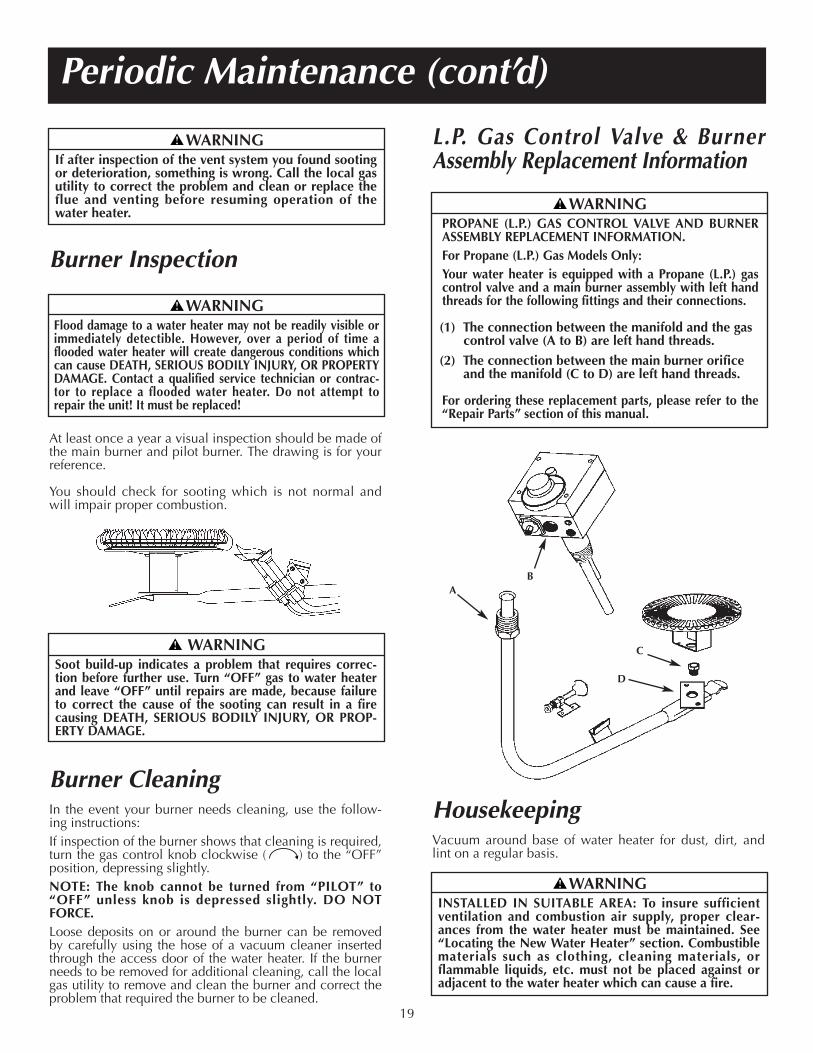
At least once a year a visual inspection should be made ofthe main burner and pilot burner. The drawing is for yourreference.
You should check for sooting which is not normal andwill impair proper combustion.
HousekeepingVacuum around base of water heater for dust, dirt, andlint on a regular basis.
WARNINGIf after inspection of the vent system you found sootingor deterioration, something is wrong. Call the local gasutility to correct the problem and clean or replace theflue and venting before resuming operation of thewater heater.
WARNINGPROPANE (L.P.) GAS CONTROL VALVE AND BURNERASSEMBLY REPLACEMENT INFORMATION.For Propane (L.P.) Gas Models Only:Your water heater is equipped with a Propane (L.P.) gascontrol valve and a main burner assembly with left handthreads for the following fittings and their connections.
(1) The connection between the manifold and the gascontrol valve (A to B) are left hand threads.
(2) The connection between the main burner orificeand the manifold (C to D) are left hand threads.
For ordering these replacement parts, please refer to the“Repair Parts” section of this manual.
WARNINGINSTALLED IN SUITABLE AREA: To insure sufficientventilation and combustion air supply, proper clear-ances from the water heater must be maintained. See“Locating the New Water Heater” section. Combustiblematerials such as clothing, cleaning materials, orflammable liquids, etc. must not be placed against oradjacent to the water heater which can cause a fire.
WARNINGSoot build-up indicates a problem that requires correc-tion before further use. Turn “OFF” gas to water heaterand leave “OFF” until repairs are made, because failureto correct the cause of the sooting can result in a firecausing DEATH, SERIOUS BODILY INJURY, OR PROP-ERTY DAMAGE.
WARNINGFlood damage to a water heater may not be readily visible orimmediately detectible. However, over a period of time aflooded water heater will create dangerous conditions whichcan cause DEATH, SERIOUS BODILY INJURY, OR PROPERTYDAMAGE. Contact a qualified service technician or contrac-tor to replace a flooded water heater. Do not attempt torepair the unit! It must be replaced!
Periodic Maintenance (cont’d)
ServiceIf a condition persists or you are uncertain about the oper-ation of the water heater, let a qualified person check itout. Call the local utility and/or plumbing contractor.
DrainingThe water heater should be drained if being shut downduring freezing temperatures. Also periodic draining andcleaning of sediment from the tank may be necessary.1. Turn the gas control knob to the “OFF” position.2. CLOSE the cold water inlet valve to the water heater.3. OPEN a nearby hot water faucet and leave open to
allow for draining.4. Connect a hose to the drain valve and terminate to an
adequate drain.5. OPEN the water heater drain valve to allow for tank
draining.NOTE: If the water heater is going to be shut downand drained for an extended period, the drain valveshould be left open with hose connected allowingwater to terminate to an adequate drain.
6. Close the drain valve.7. Follow instructions in the “Filling The Water Heater”
section.8. Follow the lighting instructions in the “Lighting” sec-
tion to restart the water heater.
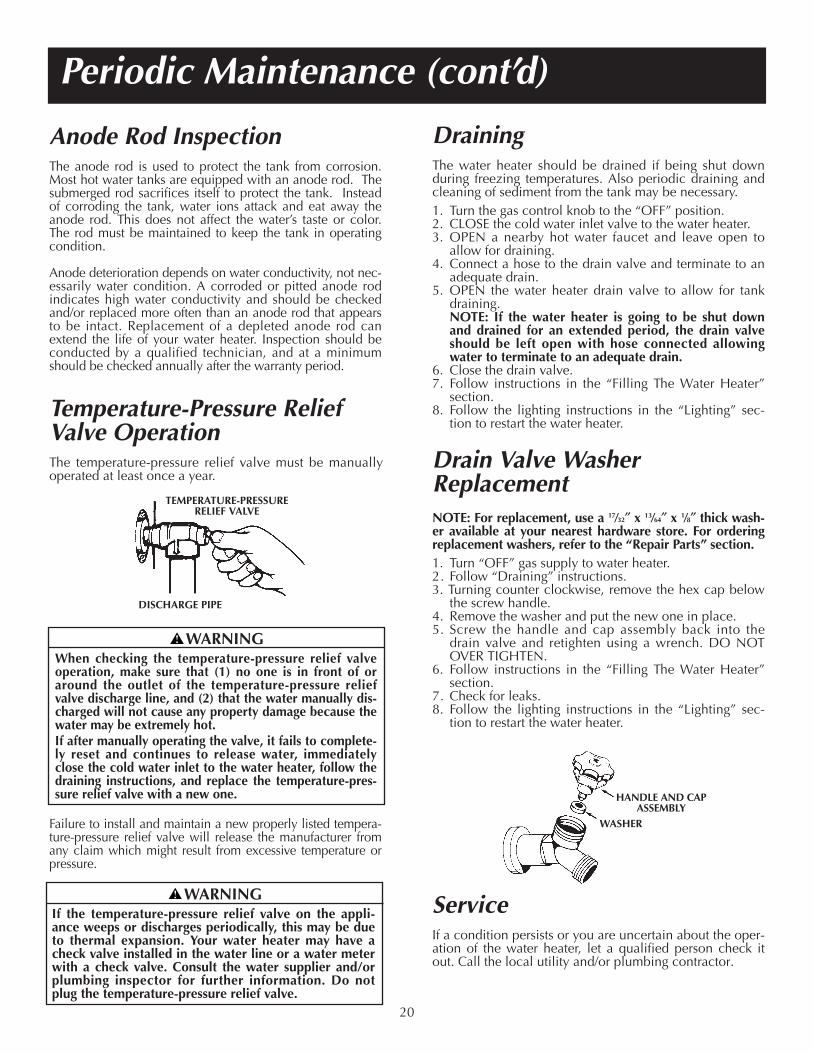
Drain Valve WasherReplacementNOTE: For replacement, use a 17⁄32″ x 13⁄64″ x 1⁄8″ thick wash-er available at your nearest hardware store. For orderingreplacement washers, refer to the “Repair Parts” section.1. Turn “OFF” gas supply to water heater.2. Follow “Draining” instructions.3. Turning counter clockwise, remove the hex cap below
the screw handle.4. Remove the washer and put the new one in place.5. Screw the handle and cap assembly back into the
drain valve and retighten using a wrench. DO NOTOVER TIGHTEN.
6. Follow instructions in the “Filling The Water Heater”section.
7. Check for leaks.8. Follow the lighting instructions in the “Lighting” sec-
tion to restart the water heater.
Failure to install and maintain a new properly listed tempera-ture-pressure relief valve will release the manufacturer fromany claim which might result from excessive temperature orpressure.
Temperature-Pressure ReliefValve OperationThe temperature-pressure relief valve must be manuallyoperated at least once a year.
20
HANDLE AND CAPASSEMBLY
TEMPERATURE-PRESSURERELIEF VALVE
DISCHARGE PIPE
WASHER
WARNINGWhen checking the temperature-pressure relief valveoperation, make sure that (1) no one is in front of oraround the outlet of the temperature-pressure reliefvalve discharge line, and (2) that the water manually dis-charged will not cause any property damage because thewater may be extremely hot.If after manually operating the valve, it fails to complete-ly reset and continues to release water, immediatelyclose the cold water inlet to the water heater, follow thedraining instructions, and replace the temperature-pres-sure relief valve with a new one.
WARNINGIf the temperature-pressure relief valve on the appli-ance weeps or discharges periodically, this may be dueto thermal expansion. Your water heater may have acheck valve installed in the water line or a water meterwith a check valve. Consult the water supplier and/orplumbing inspector for further information. Do notplug the temperature-pressure relief valve.
Anode Rod InspectionThe anode rod is used to protect the tank from corrosion.Most hot water tanks are equipped with an anode rod. Thesubmerged rod sacrifices itself to protect the tank. Insteadof corroding the tank, water ions attack and eat away theanode rod. This does not affect the water’s taste or color.The rod must be maintained to keep the tank in operatingcondition.
Anode deterioration depends on water conductivity, not nec-essarily water condition. A corroded or pitted anode rodindicates high water conductivity and should be checkedand/or replaced more often than an anode rod that appearsto be intact. Replacement of a depleted anode rod canextend the life of your water heater. Inspection should beconducted by a qualified technician, and at a minimumshould be checked annually after the warranty period.
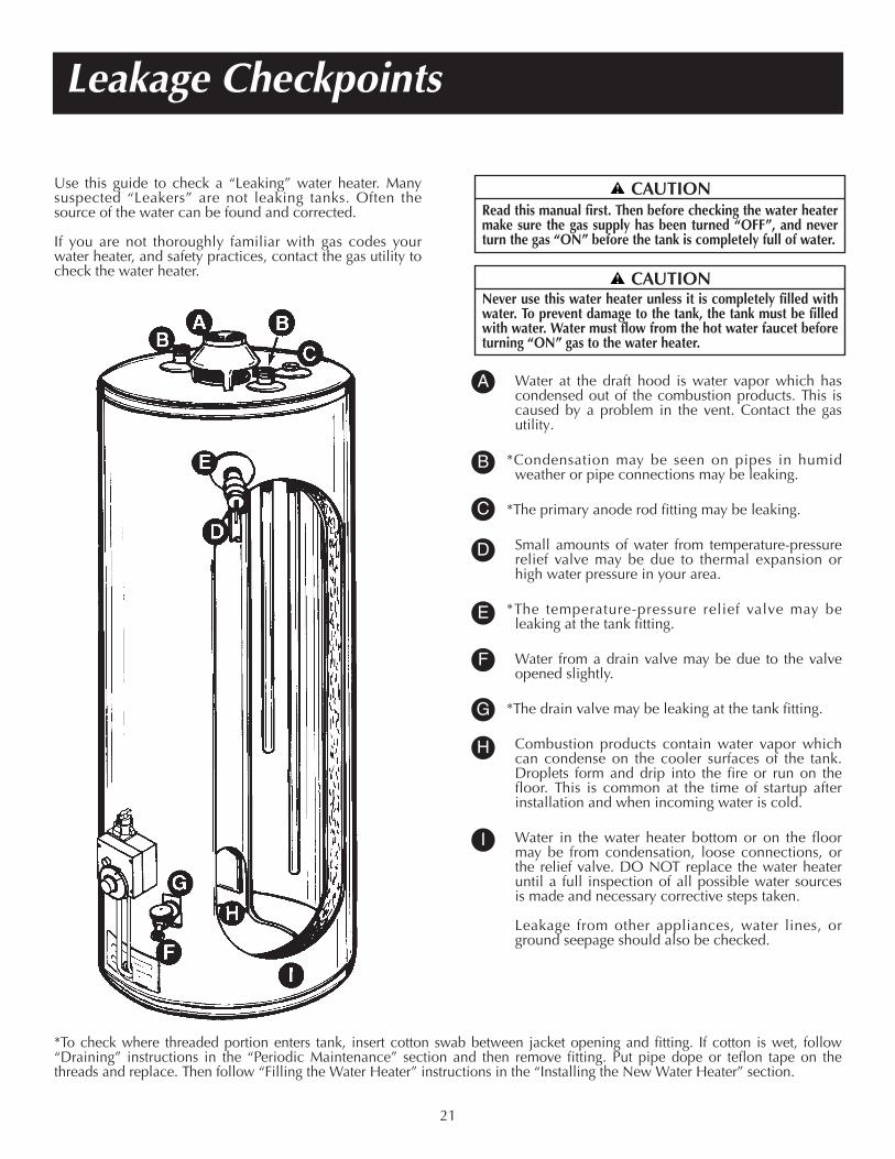
Use this guide to check a “Leaking” water heater. Manysuspected “Leakers” are not leaking tanks. Often thesource of the water can be found and corrected.
If you are not thoroughly familiar with gas codes yourwater heater, and safety practices, contact the gas utility tocheck the water heater.
Water at the draft hood is water vapor which hascondensed out of the combustion products. This iscaused by a problem in the vent. Contact the gasutility.
*Condensation may be seen on pipes in humidweather or pipe connections may be leaking.
*The primary anode rod fitting may be leaking.
Small amounts of water from temperature-pressurerelief valve may be due to thermal expansion orhigh water pressure in your area.
*The temperature-pressure relief valve may be leaking at the tank fitting.
Water from a drain valve may be due to the valveopened slightly.
*The drain valve may be leaking at the tank fitting.
Combustion products contain water vapor whichcan condense on the cooler surfaces of the tank.Droplets form and drip into the fire or run on thefloor. This is common at the time of startup afterinstallation and when incoming water is cold.
Water in the water heater bottom or on the floormay be from condensation, loose connections, orthe relief valve. DO NOT replace the water heateruntil a full inspection of all possible water sourcesis made and necessary corrective steps taken.
Leakage from other appliances, water lines, or ground seepage should also be checked.
A
B
C
D
E
F
I
H
G
*To check where threaded portion enters tank, insert cotton swab between jacket opening and fitting. If cotton is wet, follow“Draining” instructions in the “Periodic Maintenance” section and then remove fitting. Put pipe dope or teflon tape on thethreads and replace. Then follow “Filling the Water Heater” instructions in the “Installing the New Water Heater” section.
Leakage Checkpoints
21
CAUTIONRead this manual first. Then before checking the water heatermake sure the gas supply has been turned “OFF”, and neverturn the gas “ON” before the tank is completely full of water.
CAUTIONNever use this water heater unless it is completely filled withwater. To prevent damage to the tank, the tank must be filledwith water. Water must flow from the hot water faucet beforeturning “ON” gas to the water heater.
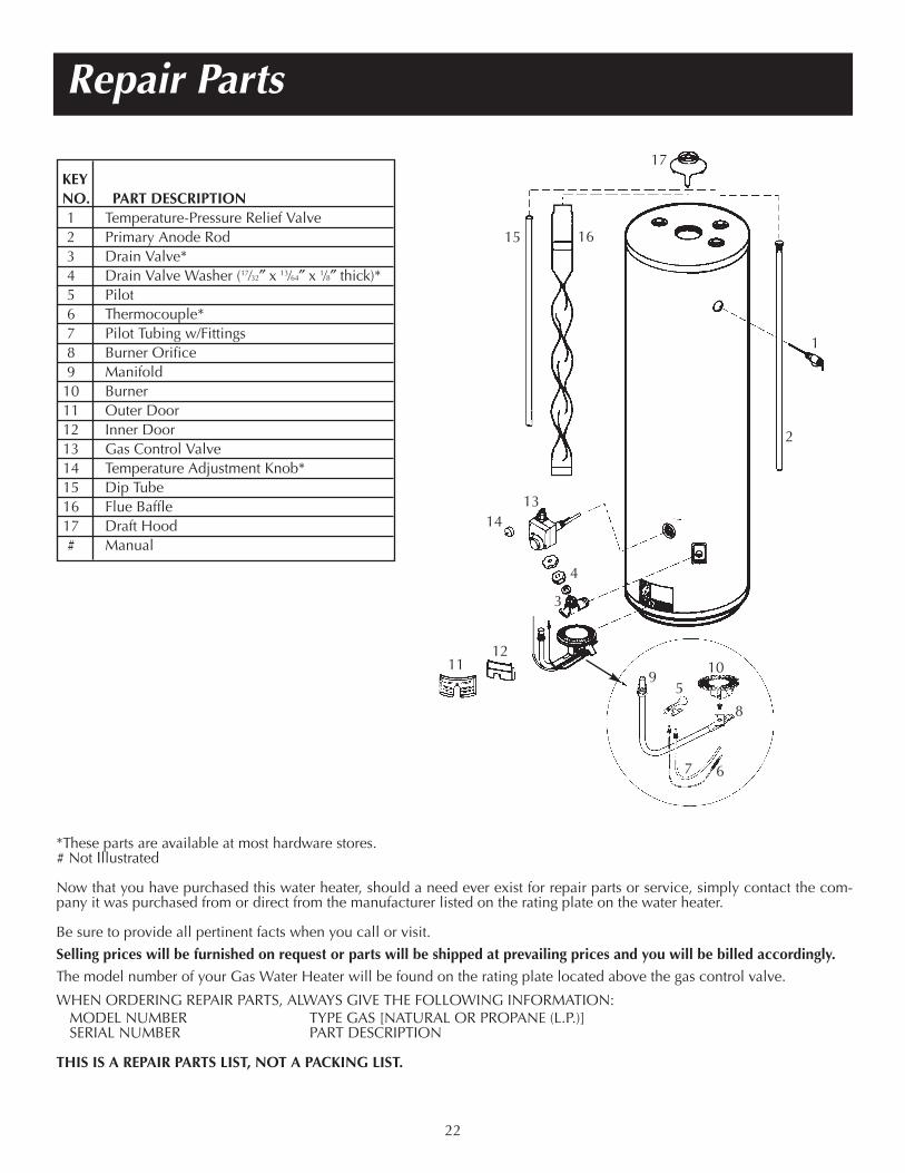
Repair Parts
*These parts are available at most hardware stores.# Not Illustrated
Now that you have purchased this water heater, should a need ever exist for repair parts or service, simply contact the com-pany it was purchased from or direct from the manufacturer listed on the rating plate on the water heater.
Be sure to provide all pertinent facts when you call or visit.
Selling prices will be furnished on request or parts will be shipped at prevailing prices and you will be billed accordingly.
The model number of your Gas Water Heater will be found on the rating plate located above the gas control valve.
WHEN ORDERING REPAIR PARTS, ALWAYS GIVE THE FOLLOWING INFORMATION:MODEL NUMBER TYPE GAS [NATURAL OR PROPANE (L.P.)]SERIAL NUMBER PART DESCRIPTION
THIS IS A REPAIR PARTS LIST, NOT A PACKING LIST.
KEYNO. PART DESCRIPTION1 Temperature-Pressure Relief Valve2 Primary Anode Rod3 Drain Valve*4 Drain Valve Washer (17⁄32″ x 13⁄64″ x 1⁄8″ thick)*5 Pilot6 Thermocouple*7 Pilot Tubing w/Fittings8 Burner Orifice9 Manifold10 Burner11 Outer Door12 Inner Door13 Gas Control Valve14 Temperature Adjustment Knob*15 Dip Tube16 Flue Baffle17 Draft Hood# Manual
1314
15 16
17
1
2
3
4
5
67
8
91011
12
22

Notes
23
